Triboelectrification-Based Organic ARTICLE Film ...
9
YANG ET AL . VOL. 8 ’ NO. 3 ’ 2649–2657 ’ 2014 www.acsnano.org 2649 February 13, 2014 C 2014 American Chemical Society Triboelectrification-Based Organic Film Nanogenerator for Acoustic Energy Harvesting and Self-Powered Active Acoustic Sensing Jin Yang, †,‡,^ Jun Chen, †,^ Ying Liu, † Weiqing Yang, † Yuanjie Su, † and Zhong Lin Wang * ,†,§ † School of Materials Science and Engineering, Georgia Institute of Technology, Atlanta. Georgia 30332-0245, United States, ‡ Department of Optoelectronic Engineering, Chongqing University, Chongqing 400044, China, and § Beijing Institute of Nanoenergy and Nanosystems, Chinese Academy of Sciences, Beijing 100083, China. ^ J.Y. and J.C. contributed equally to this work. A s a clean, ubiquitous and sustainable energy source, acoustic waves, such as various sound noises from any living activities, airports, construction sites, and traffic, are one of the wasted energies that are abundant in our daily life. Sound energy is usually taken as unwanted noise that is polluting our living environment. Acoustic energy harvesting has not been as popular as other types of energy harvest- ing, such as solar energy and thermal elec- tric energy, possibly because not only do sound waves have much lower power den- sity but also there is a lack of effective technology for harvesting such energy. 1,2 Harvesting acoustic energy has been de- monstrated using approaches based on piezoelectric 36 and electrostatic effects, 7 but their performances are limited by low energy conversion efficiency, 35 low power density, 6 structure complexity, 5 and the requirement of high-quality materials. 7 Fur- thermore, most of the presented devices generally work at high frequencies from a few kilohertz to megahertz, 3,6,7 while sound sources available in everyday life contain predominantly low frequency components, making the presented mechanisms unsui- table in most circumstances. 8 Therefore, harvesting sound wave energy remains as a challenge. Lately, we have developed innovative approaches for harnessing mechanical vibration energy using triboelectrification effect, which is an effect that has been known for thousands of years. 913 The creative * Address correspondence to [email protected]. Received for review December 11, 2013 and accepted February 3, 2014. Published online 10.1021/nn4063616 ABSTRACT As a vastly available energy source in our daily life, acoustic vibrations are usually taken as noise pollution with little use as a power source. In this work, we have developed a triboelectrification-based thin-film nanogenerator for harvesting acoustic energy from ambient environment. Structured using a polytetrafluoroethylene thin film and a holey aluminum film electrode under carefully designed straining conditions, the nanogenera- tor is capable of converting acoustic energy into electric energy via triboelectric transduction. With an acoustic sensitivity of 9.54 V Pa 1 in a pressure range from 70 to 110 dB and a directivity angle of 52°, the nanogenerator produced a maximum electric power density of 60.2 mW m 2 , which directly lit 17 commercial light-emitting diodes (LEDs). Furthermore, the nanogenerator can also act as a self-powered active sensor for automatically detecting the location of an acoustic source with an error less than 7 cm. In addition, an array of devices with varying resonance frequencies was employed to widen the overall bandwidth from 10 to 1700 Hz, so that the nanogenerator was used as a superior self-powered microphone for sound recording. Our approach presents an adaptable, mobile, and cost-effective technology for harvesting acoustic energy from ambient environment, with applications in infrastructure monitoring, sensor networks, military surveillance, and environmental noise reduction. KEYWORDS: triboelectric nanogenerator . acoustic energy harvesting . self-powered acoustic sensing ARTICLE
Transcript of Triboelectrification-Based Organic ARTICLE Film ...

YANG ET AL . VOL. 8 ’ NO. 3 ’ 2649–2657 ’ 2014
www.acsnano.org
2649
February 13, 2014
C 2014 American Chemical Society
Triboelectrification-Based OrganicFilm Nanogenerator for AcousticEnergy Harvesting and Self-PoweredActive Acoustic SensingJin Yang,†,‡,^ Jun Chen,†,^ Ying Liu,† Weiqing Yang,† Yuanjie Su,† and Zhong Lin Wang*,†,§
†School of Materials Science and Engineering, Georgia Institute of Technology, Atlanta. Georgia 30332-0245, United States, ‡Department of OptoelectronicEngineering, Chongqing University, Chongqing 400044, China, and §Beijing Institute of Nanoenergy and Nanosystems, Chinese Academy of Sciences,Beijing 100083, China. ^J.Y. and J.C. contributed equally to this work.
As a clean, ubiquitous and sustainableenergy source, acoustic waves, suchas various sound noises from any
living activities, airports, construction sites,and traffic, are one of the wasted energiesthat are abundant in our daily life. Soundenergy is usually taken as unwanted noisethat is polluting our living environment.Acoustic energy harvesting has not beenas popular as other types of energy harvest-ing, such as solar energy and thermal elec-tric energy, possibly because not only dosound waves have much lower power den-sity but also there is a lack of effectivetechnology for harvesting such energy.1,2
Harvesting acoustic energy has been de-monstrated using approaches based onpiezoelectric3�6 and electrostatic effects,7
but their performances are limited by lowenergy conversion efficiency,3�5 low powerdensity,6 structure complexity,5 and therequirement of high-quality materials.7 Fur-thermore, most of the presented devicesgenerally work at high frequencies from afew kilohertz to megahertz,3,6,7 while soundsources available in everyday life containpredominantly low frequency components,making the presented mechanisms unsui-table in most circumstances.8 Therefore,harvesting sound wave energy remains asa challenge.Lately, we have developed innovative
approaches for harnessing mechanicalvibration energy using triboelectrificationeffect, which is an effect that has been knownfor thousands of years.9�13 The creative
* Address correspondence [email protected].
Received for review December 11, 2013and accepted February 3, 2014.
Published online10.1021/nn4063616
ABSTRACT As a vastly available energy source in our daily life, acoustic
vibrations are usually taken as noise pollution with little use as a power source.
In this work, we have developed a triboelectrification-based thin-film
nanogenerator for harvesting acoustic energy from ambient environment.
Structured using a polytetrafluoroethylene thin film and a holey aluminum
film electrode under carefully designed straining conditions, the nanogenera-
tor is capable of converting acoustic energy into electric energy via triboelectric
transduction. With an acoustic sensitivity of 9.54 V Pa�1 in a pressure range
from 70 to 110 dB and a directivity angle of 52�, the nanogenerator produceda maximum electric power density of 60.2 mW m�2, which directly lit 17
commercial light-emitting diodes (LEDs). Furthermore, the nanogenerator can
also act as a self-powered active sensor for automatically detecting the location of an acoustic source with an error less than 7 cm. In addition, an array of
devices with varying resonance frequencies was employed to widen the overall bandwidth from 10 to 1700 Hz, so that the nanogenerator was used as a
superior self-powered microphone for sound recording. Our approach presents an adaptable, mobile, and cost-effective technology for harvesting acoustic
energy from ambient environment, with applications in infrastructure monitoring, sensor networks, military surveillance, and environmental noise
reduction.
KEYWORDS: triboelectric nanogenerator . acoustic energy harvesting . self-powered acoustic sensing
ARTIC
LE
YANG ET AL . VOL. 8 ’ NO. 3 ’ 2649–2657 ’ 2014
www.acsnano.org
2650
invention is proved to be capable of scavengingmechanical action/motion, such as random vibra-tions,14 rotatingmotion,15,16 wind and flowingwater,17
even ocean wave.18 As a cost-effective, simple androbust approach, the triboelectric nanogenerators pro-vide an effectivemeans for ambient energy harvesting,and its performance is superior to any existing ap-proaches of its kind.Here, we report the first organic thin-film based
triboelectric nanogenerator to scavenge ambientacoustic energy as a sustainable power source andself-powered active acoustic sensors in the low fre-quency range available in our daily life. By utilizing aHelmholtz cavity, the sensitivity of the as-fabricateddevice was as high as 9.54 V Pa�1 in the acousticpressure range from 70 dBSPL (0.063 Pa) to 110 dBSPL(6.32 Pa), and the directional pattern is in a shape ofCardioid with a total response angle of 52�. Withsuperior response to the sound waves, the rationallydesigned nanogenerator, operating at resonance fre-quency, produces a uniform signal output, with anopen-circuit voltage up to 60.5 V, a short-circuit currentamplitude of 15.1 μA, and a corresponding peak powerdensity of 60.2 mW m�2 at 110 dBSPL. The harvestedacoustic energy is demonstrated to simultaneouslylight 17 commercial light emitting diodes (LEDs) con-nected in serials. Compared to the state-of-the-artacoustic energy harvesters, the superior output perfor-mance enables considerably high energy conversionefficiency up to ∼60%. Furthermore, the as-preparednanogenerator can also act as a self-powered activesensor for acoustic source detection and sound sourcepositioning with an average error less than 7 cm, evenif the distance between the source and the acousticsensors (ASs) is more than hundreds of meters. Inaddition, the working bandwidth of the proposednanogenerator can be effectively widened when anarray of devices with varying resonance frequenciesoperating together. With an overall bandwidth from10 to 1700 Hz, the fabricated organic film nano-generators are capable of serving as a self-poweredmicrophone for sound recording. The concept anddesign presented in this work can be further appliedin a variety of other circumstances for either energy-harvesting or sensing purposes, e.g., aeroacousticsensing, jet engine noise reduction, implantablehuman ear, and wireless technology applications.
RESULTS AND DISCUSSION
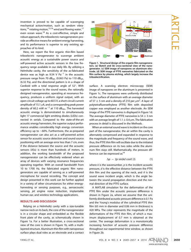
Relying on a Helmholtz cavity with a size-tunablenarrow neck on its back, the core of the nanogeneratoris in a circular shape and embedded as the flexiblefront plate of the cavity, as schematically shown inFigure 1a. For a better illustration, a cross-sectionalview of the core is shown in Figure 1b, with a multi-layered structure. Aluminum thin filmwith nanoporoussurface plays dual roles as an electrode and a contact
surface. A scanning electron microscopy (SEM)image of nanopores on the aluminum is presented inFigure 1c. The nanopores were uniformly distributedon the surface of aluminum with an average diameterof 57 ( 5 nm and a density of 210 per μm2. A layer ofpolytetrafluoroethylene (PTFE) film with depositedcopper was employed as another electrode. An SEMimage of the PTFE nanowires is displayed in Figure 1d.The average diameter of PTFE nanowires is 54 ( 3 nmwith an average length of 1.1( 0.4 μm. The fabricationprocess in detail is discussed in the Methods.When an external soundwave is incident on the core
part of the nanogenerator, the air within the cavity isalternately compressed and expanded in response tothe magnitude and frequency of the sound wave, andthus, the PTFE thin filmwill oscillate due to the initiatedpressure difference on its two sides while the alumi-num film stays still. Mathematically, the pressure dif-ference can be expressed as19
Δp ¼ 2p sin(kd cosθ=2) (1)
where k is the wavenumber, p is the incident acousticpressure, d is the effective distance between the PTFEthin film and the opening of the neck, and θ is thesound wave incident angle, which is the angle be-tween the sound propagation direction and the nor-mal direction of the PTFE surface.A MATLAB simulation for the deformation of the
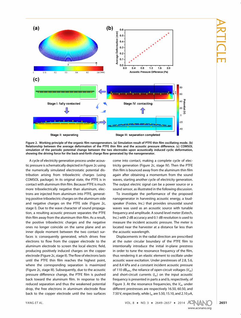
PTFE film under the acoustic pressure difference isshown in Figure 2a, where we assume that the uni-formly distributed acoustic pressure difference is 0.1 Paand the Young's modulus of the cylindrical PTFE thinfilm (65 mm in diameter and 0.06 mm in thickness) is420 MPa. The color represents the magnitude of thedeformations of the PTFE thin film, of which a max-imum displacement of 0.7 mm is obtained at thecenter. The average deformation is a monotonicallyincreasing function of acoustic pressure differencethroughout our experimental time window, as shownin Figure 2b.
Figure 1. Structural design of the organic film nanogenera-tors. (a) Sketch and (b) cross-sectional view of the nano-generator. (c) SEM image of nanopores on aluminum elec-trode. (d) SEM image of PTFE nanowires fabricated on thefilm surface by plasma etching, which largely increase thetriboelectrification.
ARTIC
LE
YANG ET AL . VOL. 8 ’ NO. 3 ’ 2649–2657 ’ 2014
www.acsnano.org
2651
A cycle of electricity generation process under acous-tic pressure is schematically depicted in Figure 2c usingthe numerically simulated electrostatic potential dis-tribution arising from triboelectric charges (usingCOMSOL package). In its original state, the PTFE is incontact with aluminum thin film. Because PTFE ismuchmore triboelectrically negative than aluminum, elec-trons are injected from aluminum into PTFE, generat-ing positive triboelectric charges on the aluminum sideand negative charges on the PTFE side (Figure 2c,stage I). Due to the wave character of sound propaga-tion, a resulting acoustic pressure separates the PTFEthin film away from the aluminum thin film. As a result,the positive triboelectric charges and the negativeones no longer coincide on the same plane and aninner dipole moment between the two contact sur-faces is consequently generated, which drives freeelectrons to flow from the copper electrode to thealuminum electrode to screen the local electric field,producing positively induced charges on the copperelectrode (Figure 2c, stage II). The flowof electrons lastsuntil the PTFE thin film reaches the highest point,where the corresponding separation is maximized(Figure 2c, stage III). Subsequently, due to the acousticpressure difference change, the PTFE film is pushedback toward the aluminum film. In response to thereduced separation and thus the weakened potentialdrop, the free electrons in aluminum electrode flowback to the copper electrode until the two surfaces
come into contact, making a complete cycle of elec-tricity generation (Figure 2c, stage IV). Then the PTFEthin film is bounced away from the aluminum thin filmagain after obtaining a momentum from the soundwaves, starting another cycle of electricity generation.The output electric signal can be a power source or asound sensor, as illustrated in the following discussion.To investigate the performance of the proposed
nanogenerator in harvesting acoustic energy, a loud-speaker (Fostex, Inc.) that provides sinusoidal soundwaves was used as an acoustic source with tunablefrequency and amplitude. A sound level meter (Extech,Inc.) with 2 dB accuracy and 0.1 dB resolution is used tomeasure the incident acoustic pressure. The meter islocated near the harvester at a distance far less thanthe acoustic wavelength.Displacements in the radial direction are prescribed
at the outer circular boundary of the PTFE film tointentionally introduce the initial in-plane prestressin order to tune the resonance frequency of the film,thus rendering it an elastic element to oscillate underacoustic wave excitation. Under prestresses of 2.8, 5.6,and 8.4 kPa and a constant incident acoustic pressureof 110 dBSPL, the reliance of open-circuit voltages (Voc)and short-circuit currents (Isc) on the input acousticfrequency is presented in parts a and b, respectively, ofFigure 3. At the resonance frequencies, the Voc underdifferent prestresses are respectively 16.50, 60.50, and7.50 V, respectively, while Isc are 5.50, 15.10, and 2.10 μA,
Figure 2. Working principle of the organic film nanogenerators. (a) Simulation result of PTFE thin film oscillating mode. (b)Relationship between the average deformation of the PTFE thin film and the acoustic pressure difference. (c) COMSOLsimulation of the periodic potential change between the two electrodes upon acoustically induced cyclic deformation,showing the driving force for the back-and-forth charge flow generated by the nanogenerator.
ARTIC
LE

YANG ET AL . VOL. 8 ’ NO. 3 ’ 2649–2657 ’ 2014
www.acsnano.org
2652
respectively. The output voltage shows an enhance-ment of 3.7 times for the device with a prestress of5.6 kPa than that with the prestress of 2.8 kPa, and alsoan enhancement of 8.1 times is achieved compared tothe device with prestress of 8.4 kPa. The results showthat a suitable initial prestress can optimize the oscilla-tion coupling between the air trapped in the cavity andPTFE thin film and, thus, the electrical output.Regarding the optimized design, namely, the device
with prestress of 5.6 kPa, experimentally, both Voc andIsc are maximized at the acoustic frequency of 240 Hz,indicating that 240 Hz is the resonance frequencyof the as-fabricated generator. The output voltageand current at the resonance frequency of 240 Hz aredemonstrated in Figure S1 (Supporting Information).Theoretically, if the dimensions of the device aresmaller than or comparable to the incident acousticwavelength, its dynamic behavior can bemodeled as alumped system and its resonant frequency can beexpressed as20
fR ¼ c
2π
ffiffiffiffiffiffiffiS
L0V
r(2)
where S and L0 are, respectively, the cross-sectionalarea and effective length of the neck, V is the cavityvolume, and c is the speed of sound in air (343 m s�1).Submitting the values into eq 2, we can obtain thetheoretical natural frequency of 238.8 Hz, which isconsistent with the experimental results.In addition, the prestress has amarked impact on the
electric output of the device, aimed at further improv-ing the electric output, and a series of acoustic holesare punched through the aluminum electrode, whichact as communicating vessels to integrate the airgap between two contact surfaces with the air in thecavity. The open ratio (OR) is defined as the area ratioof all acoustic holes' area to the surface area of the
aluminum electrode, which largely influences thedamping of the air. A larger value of OR results in ahigher flow velocity and lower damping,21 which willcontribute to a larger deformation of the PTFE filmunder the same acoustic pressure excitation. Under aconstant acoustic pressure of 110 dBSPL, the Voc andIsc of the generatorwith differentORs of 0.1, 0.3, and 0.5were respectively measured, as shown in parts c and dof Figure 3. At the resonance frequencies, the Voc foropen ratios of 0.1, 0.3, and 0.5 are, respectively, 35.20,60.50, and 18.70 V, and the corresponding Isc are8.20, 15.10, and 5.50 μA. The results indicate that anenhancement of 1.7 times the electric output is ob-tained for the device with anOR value of 0.3, comparedto that of 0.1, and also an enhancement of 3.2 times isachieved compared to that of 0.5. This experimentalobservation is resulted from a trade-off between thePTFE deformation and the effective contact area.Larger OR leads to a larger deformation of the PTFEthin film and thus a higher electric output. However,increased OR will reduce the effective contact area fortriboelectrification, and thus a lower electrical output.Consequently, an optimum OR is needed to maximizethe electrical output.Upon the optimization of device design with appro-
priate prestress and OR, a further step is made towardinvestigating the relationship between the deviceelectrical outputs and applied acoustic power andfrequency. The acoustic frequencies are spreadingfrom 0 to 500 Hz, and the corresponding acousticpressure ranging from 70 dBSPL to 110 dBSPL in a stepof 5 dBSPL is controlled and measured by the soundlevel meter. The electric output is highly related tothe input acoustic pressures and frequencies, and de-tailed relationships are demonstrated in Figure 4a,b.As shown, at the resonant frequency of 240 Hz, withdecreasing acoustic pressure from 110 dBSPL to 70dBSPL, the Voc is decreased from 60.50 to 0.73 V andthe short-circuit current is decreased from 15.10 to0.19 μA. Based on the experimental results, a MATLABfitting renders a linear relationship between the open-circuit voltage (Voc) and the applied acoustic pressurePin (in Pascal), which can be expressed as
Voc ¼ 9:54Pin þ 0:13 (3)
The sensitivity of the generator as a pressure sensorwas 9.54 V Pa�1 in the acoustic pressure range from0.063 Pa (70 dBSPL) to 6.32 Pa (110 dBSPL) at a frequencyof 240 Hz.Furthermore, the acoustic waves decay in the course
of propagation; thus, the distance of the measureddevice to the acoustic source shows a tremendousimpact on the electric output for acoustic energyharvesters. At a fixed acoustic pressure of 110 dBSPLand resonant frequency of 240 Hz, a distance de-pended electric output is measured, as shown inFigure 4c. The open-circuit voltage is decreased from
Figure 3. Electrical measurement of the organic film nano-generators. (a) Open-circuit voltages (VOC) and (b) short-circuit currents (ISC) as a function of acoustic frequency withdifferent prestresses of 2.8, 5.6, and 8.4 kPa. The curves arethe fitted results. (c) VOC and (d) ISC as a function of acousticfrequency with different open ratios (ORs) of 0.1, 0.3, and0.5. The curves are the fitted results.
ARTIC
LE

YANG ET AL . VOL. 8 ’ NO. 3 ’ 2649–2657 ’ 2014
www.acsnano.org
2653
60.50 to 0.81 V, with short-circuit current decreasingfrom 15.10 to 0.21 μA when the distance is increasedfrom 1 to 100 cm. It is worth noting that the electricoutput attenuates at a rate of 6 dB each time thedistance from the acoustic source doubles.For a comprehensive study of the proposed acoustic
energy harvester, we took a further step to evaluate thedirectional dependence (directivity) pattern of the as-fabricated devices. We anchored the device onto arotary stage and then gradually increased the rotatingangle from 0 to 360� and measured the Voc at theresonant acoustic frequency of 240 Hz. The corre-sponding directional pattern is obtained by normal-izing relative to the peak response of voltage, asillustrated in Figure 4d. The test results show thatthe pattern is in shape of Cardioid and smooth asa function of rotating angle, and the�3 dB points areatþ26� and�26� off axis, producing a total responseangle of 52�. At an angle of 90�, the sound pres-sure level is reduced to �28 dB from the maximumvalue on-axis. The acoustic response of the devicehas a dependence on the incident angle of the soundwaves, which is actually the stage rotating angle inthe measurement. As a sound filter, the as-fabricateddevice is sensitive to the sound coming from direc-tions within the response angle and rejects thecontribution from other angles, which renders it agreat potential in the application of directionalmicrophones.
Resistors were utilized as external loads to fur-ther investigate the useful output power of the as-fabricated nanogenerator at the resonance frequency.As displayed in Figure 5a, the voltage amplitudesincrease with increasing load resistance, while the cur-rent follows a reverse trend owing to theOhmic loss. Asa result, the instantaneous peak power (V2/R)peak ismaximized at a load resistance of 6MΩ, correspondingto a peak power density of 60.2 mWm�2 (Figure 5b). Toprove the capability of the proposed nanogeneratoras a sustainable power source, powered by a nano-generator with the cavity dimensions of 8 cm� 8 cm�8 cm under acoustic pressure of 110 dBSPL at theresonant frequency of 240 Hz, 17 commercial LEDbulbs were lit simultaneously, as demonstrated in theinset of Figure 5b, as visualized in supporting movie 1(Supporting Information).As an acoustic energy harvesterwith superior output
performance, the as-fabricated nanogenerators arealso capable of acting as active self-powered acousticsensors. A series of practical applications were demon-strated. The first demonstration for the nanogenera-tors is to act as a self-poweredmicrophone. The naturalfrequencies of the devices can be designed by param-eters configuration, and their corresponding frequencybands are able to overlap with each other, renderingus a broadened working bandwidth. Here, as de-monstrated in Figure 6a, four nanogenerators, NG1,NG2, NG3, and NG4, respectively, with dimensions
Figure 4. Electrical and acoustical performance evaluation of the organic film nanogenerators. (a) VOC and (b) ISC as a functionof acoustic pressures and frequencies. (c) Nanogenerator acts as an active acoustic sensor for distancemeasurement aswell asambient acoustic source detection. When a sound source approaching the nanogenerator, the output signal is exponentiallyincreased. (d) Directional pattern of the nanogenerator.
ARTIC
LE

YANG ET AL . VOL. 8 ’ NO. 3 ’ 2649–2657 ’ 2014
www.acsnano.org
2654
of 11 mm� 11 mm� 11 mm, 9 mm� 9 mm� 9 mm,7 mm � 7 mm � 7 mm, and 5 mm � 5 mm � 5 mm,corresponding to resonance frequencies of 350, 650,1100, and 1400Hz, were employed towiden the overallworking bandwidth from 10 to 1700 Hz, which assuredthe superior performance of the nanogenerators asa self-powered microphone for sound recording. Forexperimental measurements, a multichannel signal
acquisition implant was designed by LabVIEW to col-lect the electric outputs at a sampling rate of 44.1 kHz.Parts b1 and b3 of Figure 5 are, respectively, the timedomain waveforms of the recorded sounds fromNG1 and NG4. Although NG1 and NG4 share the samesound source, the waveforms of the two apparentlyexhibit different characteristics, which is attributed to adifferent frequency response ranges of the two. With a
Figure 5. Demonstration of the organic film nanogenerator acting as a sustainable power source. (a) Dependence of thevoltage and current output on the external load resistance. The points represent peak value of electric signals, while the linesare the fitted results. (b) Dependence of the peak power output on the resistance of the external load, indicating maximumpower output at R= 6MΩ. The curve is the fitted result. Inset is a photograph that shows how the nanogeneratorworks underexcitation from a sound box. Due to the external sound, 17 LEDs are being lighted up simultaneously.
Figure 6. Demonstration of the organic film nanogenerator acting as a self-powered microphone. (a) Frequency responsesfrom the nanogenerators array, which consists of four NGs with various designed natural frequencies, aimed to enhance theoverall workingbandwidth. (b1, b2) Soundwaveformsof the signals acquiredbyNG1 andNG2, respectively. (b3, b4) Short-timeFourier transforms of the acquired signals by NG1 and NG2, respectively. (c) Sound waveform and corresponding short-timeFourier transformof the signals acquired by the array of theNGs. (d) Photograph that shows aNG isworking as a self-poweredmicrophone for sound recording.
ARTIC
LE

YANG ET AL . VOL. 8 ’ NO. 3 ’ 2649–2657 ’ 2014
www.acsnano.org
2655
natural frequency of 350 Hz, the waveform of NG1 issmoother owing to its dominant response to lowerfrequency components from 10 to 600 Hz, as shown inFigure 5b2, which is the corresponding short-timeFourier transform (STFT), while the waveform of NG4
with a natural frequency of 1400 Hz is rougher, due toits dominant response to the higher frequency com-ponents from 1100 to 1700 Hz, as demonstrated inFigure 5b4 of its corresponding STFT.In order to reconstruct the original sound, the
acquired acoustic signals of the array are weightedaccording to the relative amount of information avail-able from each source. The reconstructed signal Sre canbe mathematically expressed as
Sre ¼ ∑4
i¼ 1aisi (4)
where ai is a weighting factor, which is a functionof speech-to-noise following a rule of Σi=1
4 ai = 1 andsi is the acquired output acoustic signal from NGi
(i = 1�4).The waveform of the reconstructed signal by eq 4
and its corresponding STFT are illustrated in parts c1and c2, respectively, of Figure 6. The frequency com-ponents of the reconstructed signal cover all thefrequencies ranging from 10 to 1700 Hz, as demon-strated in Figure 6c2. Figure 6d shows an as-fabricationnanogernator working as a self-powered microphone
for sound recording, as visualized in supporting movie2 (Supporting Information).The second demonstration of the nanogenerator for
sensing purpose is to act an acoustic source localiza-tion sensor. Experimentally, three as-fabricated nano-generators were arranged in an L shape and anchoredin a 2-dimensional (2D) plane with dimensions of 2 mby 1.8 m, as schematically shown in Figure 7a and acorresponding photograph in Figure 7b. The soundwas created by bursting a small balloon in the 2D planeas acoustic sources. A customized triple-channel dataacquisition system based on LabVIEW was used tocollect the sensing signals from ASs. Figure 7c eluci-dates the acoustic signals acquired by the ASs whena balloon burst at the center of the 2D plane. Whenanother balloon bursting spot is settled with variousdistances to the ASs, the three acoustic signals showobvious discrepancies in response starting time andmagnitude, as demonstrated in Figure S2a (SupportingInformation).The acoustic localization algorithm presented in
this work is based on the estimation of the timedifference of arrival (TDOA) at pairs of acoustic sensors.Let Sk = [Xk,Yk]
T denote the location of kth ASwith k = 1,2, 3. Let P= [x, y]T represents the location of the acousticsource. Then, the distance d(P, Sk) between acousticsource and the kth sensor can be expressed as
d(P, Sk) ¼ jjSk � P jj (5)
Figure 7. Demonstration of the organic film nanogenerator acting as an active sensor for acoustic source localization. (a)Schematic illustrations and (b) photograph showing the working mechanism of nanogenerators for sound localization. (c)Acquired acoustic signals from the three nanogenerators when a balloon burst. (d) Correlation functions of the acquiredacoustic signals from AS 1, 2 and 3.
ARTIC
LE
YANG ET AL . VOL. 8 ’ NO. 3 ’ 2649–2657 ’ 2014
www.acsnano.org
2656
and the time delay in TDOA at Si and Sj is given by
τij(P) ¼ (d(P, Si) � d(P, Sj))=c (6)
where i, j = 1�3 and i 6¼ j. The in-pair evaluating TDOAof acquired signals by ASs can be achieved by comput-ing the cross-correlation function of these two signals.Let zi(n) and zj(n) denote the signals acquired by ASiand ASj, respectively, where n is the sample time index.Then, the cross-correlation function Rzi,zj(τ) betweenASi and ASj is defined as
Rzi , zj (τ) ¼ ∑N
n¼ 1zi(n)zj(nþ τij) (7)
where N is the number of the sample points. The timedifference between the two acquired signals is esti-mated by the time lag at the highest peaks of theircross-correlation functions. Two correlation functionsof the three acquired acoustic signals in Figure 7c werederived from eq 7, as shown in Figure 7d. It is worthnoting that the time lags of the two cross-correlationfunctions between AS1 and AS2 as well as AS2 and AS3are zero, indicating the samedistance is traveled by thesound from the acoustic source to the ASs, which iswell consistent with the real experimental case. For thecase of acoustic source with various distances to theASs, two cross-correlation functions calculated basedon Figure S2a (Supporting Information) are demon-strated in Figure S2b (Supporting Information), fromwhich the values of τ12 and τ23 are obtained, and equalto �1.3 and 3 ms, respectively, consistent with the ex-perimental results. Give the distances between thethree acoustic sensors and also the in-pair time delayinformation, the acoustic source can be localized/positioned as the intersection of the two hyperboliccurves by virtue of the speed of sound and geometry.22
Experimentally, positioning within an average errorcircle of 7 cm in diameter is achieved based onmultiplemeasurements, which mainly depends on the signal-to-noise ratio (SNR)23 if the SNR of the acquired signalsare comparable with each other, and the error will staywithin a same average error circle even if the distancebetween the source and the ASs ismore than hundredsof meters. A visualized demonstration of the nano-generators for acoustic source localization is presentedin supporting movie 3 (Supporting Information). The
proposed acoustic sensors in this work have extensiveapplications in fields such as military surveillance andreconnaissance, intruder detection, sniper localization,underwater acoustics, and auto talker detection in aweb conferencing.Additionally, the as-fabricated nanogenerator can
be harnessed for mass measurement. The workingprinciple of mass measurement is schematically de-monstrated (Figure S3a, Supporting Information). Dif-ferent loads will lead to different deformations of themembrane under the same sound pressure excitationand, thus, different output voltages of the acousticsensors. Experimental results show that the voltageoutput is a monotonically decreasing function of theapplied mass throughout our experimental time win-dow with a sensitivity of 270 mV/mg (Figure S3b,supportingmovie 4, Supporting Information). By virtueof the triboelectric effect based mass measurement,the weight increment of the applied mass can also bemeasured.
CONCLUSIONS
We developed a new type of acoustic energy har-vester that scavenges energy using triboelectrificationeffect, a universal phenomenon upon contact betweentwo materials with opposite triboelectric polarities.Rationally designed structure, coupled with nano-material modification, the as-fabricated nanogenera-tor enables superior performance in harvesting ambi-ent acoustic energy. It produced a maximum electricpower density of 60.2 mW 3m
�2, which directly lightedup 17 commercial LEDs simultaneously. The as-fabri-cated nanogenerators were also proved to be activeself-powered acoustic sensors for sound recording,acoustic source localization, as well as mass measure-ment. This work not only presents an adaptable, cost-effective, and fundamentally new approach for ambi-ent acoustic energy harvesting but also a milestoneprogress in nanogenerator-based active sensors. Theconcept and design presented in this work can befurther applied in a variety of circumstances for eitherenergy-harvesting or sensing purposes, e.g., aero-acoustic sensing, jet engine noise reduction, militarysurveillance, and reconnaissance as well as wirelesstechnology applications.
METHODSNanopore-Based Aluminum Surface Modification. The electro-
chemical anodization was applied on aluminum foil in 3%(mass fraction) oxalic acid (H2C2O4) electrolyte. The aluminumfoil was anodized under a bias voltage of 30 V for 5 h with aplatinum plate acting as the cathode. After that, the alumina layerwas etched away in a solution of chromic acid (20 g L�1) at 60 �Cfor 2 h. Then the aluminum foil was rinsedwithDIwater anddriedin air.
Nanowire-Based PTFE Surface Modification. A PTFE film (50 μmthick) was first washed using menthol, isopropyl alcohol, and
deionized water. Then, a layer of 100 nm copper was depositedonto this PTFE thin film usingDC sputter for the etching process.Subsequently, the inductively coupled plasma (ICP) reactive ionetching was used to fabricate the aligned nanowires on thePTFE surface. O2, Ar, and CF4 gases were injected into the ICPchamber with a flow ratio of 10.0, 15.0, and 30.0 sccm, respec-tively. A large density of plasma was produced by a powersource of 400 W, and another power source of 100 W was usedto accelerate the plasma ions. The PTFE nanowires with anaverage length of ∼1.1 μm were obtained after the PTFE filmwas etched for 40 s.
ARTIC
LE

YANG ET AL . VOL. 8 ’ NO. 3 ’ 2649–2657 ’ 2014
www.acsnano.org
2657
Fabrication of the Nanogenerator. To fabricate the nanogenera-tor, a cubic cavity with dimensions of 80 mm by 80 mm by80 mm was first constructed using acrylic sheet (thickness of0.25 in.). A narrow neck with dimensions of 28 mm� 28 mm�80 mm is anchored into the back plate of the cavity. The coreof the nanogenerator is in a circular shape with a diameterof 65mm and embedded as the flexible front plate of the cavity.The core part has a multilayer structure. Aluminum thin filmwith a thickness of 0.5mmplays dual roles of an electrode and acontact surface. Eight acoustic holes with diameter of 12.6 mmare designed into the aluminum electrode acting as commu-nicating vessels to integrate the air gap between two contactsurfaces with the air in the cavity. A layer of copper wasdeposited onto the PTFE filmwith thickness of 50 μmas anotherelectrode.
Conflict of Interest: The authors declare no competingfinancial interest.
Acknowledgment. This work was supported by the U.S.Department of Energy, Office of Basic Energy Sciences (DE-FG02-07ER46394), the “Thousands Talents” program for pio-neering researchers and their innovation team, China, and theNSFC (No. 61174017).
Supporting Information Available: Electrical measurement ofthe organic film nanogenerator; demonstration of the organicfilm nanogenerator acting as an active sensor for acousticsource localization; demonstration of the organic film nano-generator acting as a self-powered acoustic sensor for massmeasurement; supportingmovies 1�4. Thismaterial is availablefree of charge via the Internet at http://pubs.acs.org.
REFERENCES AND NOTES1. Wang, X. D.; Song, J. H.; Wang, Z. L. Direct-Current Nano-
generator Driven by Ultrasonic Waves. Science 2007, 316,102–105.
2. Wang, X. D.; Liu, J.; Song, J. H.; Wang, Z. L. IntegratedNanogenerators in Biofluid. Nano Lett. 2007, 7, 2475–2479.
3. Cha, S. N.; Seo, J-. S.; Kim, S. M.; Kim, H.; Park, Y. J.; Kim, S.;Kim, J. M. Sound-Driven Piezoelectric Nanowire-BasedNanogenerators. Adv. Mater. 2010, 22, 4726–4730.
4. Xu, C.; Wang, X. D.; Wang, Z. L. Nanowire Structured HybridCell for Concurrently Scavenging Solar and MechanicalEnergies. J. Am. Chem. Soc. 2009, 131, 5866–5872.
5. Hansen, B. J.; Liu, Y.; Yang, R.; Wang, Z. L. Hybrid Nanogen-erator for Concurrently Harvesting Biomechanical andBiochemical Energy. ACS Nano 2010, 4, 3647–3652.
6. Yang, R.; Qin, Y.; Dai, L.; Wang, Z. L. Power Generation withLaterally-Packaged Piezoelectric Fine Wires. Nat. Nano-technol. 2009, 4, 34–39.
7. Que, R. H.; Shao, Q.; Li, Q. L.; Shao, M. W.; Cai, S. D.; Wang,S. D.; Lee, S. T. Flexible Nanogenerators Based on Gra-phene Oxide Films for Acoustic Energy Harvesting. Angew.Chem., Int. Ed. 2012, 51, 5418–5422.
8. Mei, J.; Ma, G. C.; Yang, M.; Yang, Z. Y.; Wen, W. J.; Sheng, P.Dark Acoustic Metamaterials as Super Absorbers for Low-Frequency Sound. Nat. Commun. 2012, 3, 756.
9. Fan, F. R.; Tian, Z. Q.; Wang, Z. L. Flexible TriboelectricGenerator!. Nano Energy 2012, 1, 328–334.
10. Zhu, G.; Pan, C. F.; Guo, W. X.; Chen, C. Y.; Zhou, Y. S.; Yu,R. M.; Wang, Z. L. Triboelectric-Generator-Driven PulseElectrodeposition for Micropatterning. Nano Lett. 2012,12, 4960–4965.
11. Zhu, G.; Chen, J.; Liu, Y.; Bai, P.; Zhou, Y. S.; Jing, Q. S.; Pan,C. F.; Wang, Z. L. Linear-Grating Triboelectric GeneratorBased on Sliding Electrification. Nano Lett. 2013, 13, 2282–2289.
12. Yang, J.; Chen, J.; Yang, Y.; Zhang, H. L.; Yang, W. Q.; Bai, P.;Su, Y. J.; Wang, Z. L. Broadband Vibrational Energy Harvest-ing Based on a Triboelectric Nanogenerator. Adv. EnergyMater. 2013, 10.1002/aenm.201301322.
13. Yang, W. Q.; Chen, J.; Zhu, G.; Yang, J.; Bai, P.; Su, Y. J.; Jing,Q. S.; Cao, X.; Wang, Z. L. Harvesting Energy from the
Natural Vibration of Human Walking. ACS Nano 2013, 7,11317–11324.
14. Chen, J.; Zhu, G.; Yang, W. Q.; Jing, Q. S.; Bai, P.; Yang, Y.;Hou, T. C.; Wang, Z. L. Harmonic-Resonator-Based Tribo-electric Nanogenerator as a Sustainable Power Source anda Self-Powered Active Vibration Sensor. Adv. Mater. 2013,25, 6094–6099.
15. Bai, P.; Zhu, G.; Liu, Y.; Chen, J.; Jing, Q. S.; Yang,W. Q.; Ma, J.;Zhang, G.; Wang, Z. L. Cylindrical Rotating TriboelectricNanogenerator. ACS Nano 2013, 7, 6361–6366.
16. Lin, L.; Wang, S. H.; Xie, Y. N.; Jing, Q. S.; Niu, S. M.; Hu, Y. F.;Wang, Z. L. Segmentally Structured Disk TriboelectricNanogenerator for Harvesting Rotational Mechanical En-ergy. Nano Lett. 2013, 13, 2916–2923.
17. Yang, Y.; Zhu, G.; Zhang, H. L.; Chen, J.; Zhong, X. D.; Lin,Z. H.; Su, Y. J.; Bai, P.; Wen, X. N.; Wang, Z. L. TriboelectricNanogenerator for Harvesting Wind Energy and as Self-Powered Wind Vector Sensor System. ACS Nano 2013, 7,9461–9469.
18. Hu, Y. F.; Yang, J.; Jing, Q. S.; Niu, S. M.; Wu, W. Z.; Wang, Z. L.Triboelectric Nanogenerator Built on Suspended 3D SpiralStructure as Vibration and Positioning Sensor and WaveEnergy Harvester. ACS Nano 2013, 7, 10424–10432.
19. Sessler, G. M.; West, J. E. First-Order Gradient MicrophoneBased on the Foil-Electret Principle: DiscriminationAgainst Air-Borne and Solid-Borne Noises. J. Acoust. Soc.Am. 1969, 46, 1081–1086.
20. Hu, X. H.; Ho, K. M. Homogenization of Acoustic Metama-terials of Helmholtz Resonators in Fluid. Phys. Rev. B. 2008,77, 172301.
21. Her, H. C.; Wu, T. L.; Huang, J. H. Acoustic Analysis andFabrication of Microelectromechanical System CapacitiveMicrophones. J. Appl. Phys. 2008, 104, 084509.
22. Kundu, T. Acoustic Source Localization. Ultrasonics 2014,54, 25–38.
23. Jacovitti, G.; Scarano, G. Discrete Time Techniques for TimeDelay Estimation. IEEE Trans. Signal Process. 1993, 41, 525–533.
ARTIC
LE