Tribo-Mechanical Properties of HVOF Deposited Fe3Al Coatings … · 2019-03-03 · materials...
16
materials Article Tribo-Mechanical Properties of HVOF Deposited Fe 3 Al Coatings Reinforced with TiB 2 Particles for Wear-Resistant Applications Mahdi Amiriyan 1,2 , Carl Blais 1,2 , Sylvio Savoie 3 , Robert Schulz 3 , Mario Gariépy 4 and Houshang Alamdari 1,2, * 1 Département de génie des mines, de la métallurgie et des matériaux, Université Laval, Québec, QC G1V 0A6, Canada; [email protected] (M.A.); [email protected] (C.B.) 2 Aluminium Research Centre-REGAL, Québec, QC G1V 0A6, Canada 3 Hydro-Quebec Research Institute, Varennes, QC J3X 1S1, Canada; [email protected] (S.S.); [email protected] (R.S.) 4 Weir American Hydro, Weir Canada Inc., LaSalle, QC H8N 1V1, Canada; [email protected] * Correspondence: [email protected]; Tel.: +1-418-656-7666 Academic Editor: Daolun Chen Received: 26 November 2015; Accepted: 15 February 2016; Published: 19 February 2016 Abstract: This study reveals the effect of TiB 2 particles on the mechanical and tribological properties of Fe 3 Al-TiB 2 composite coatings against an alumina counterpart. The feedstock was produced by milling Fe 3 Al and TiB 2 powders in a high energy ball mill. The high-velocity oxy-fuel (HVOF) technique was used to deposit the feedstock powder on a steel substrate. The effect of TiB 2 addition on mechanical properties and dry sliding wear rates of the coatings at sliding speeds ranging from 0.04 to 0.8 m¨ s ´1 and loads of 3, 5 and 7 N was studied. Coatings made from unreinforced Fe 3 Al exhibited a relatively high wear rate. The Vickers hardness, elastic modulus and wear resistance of the coatings increased with increasing TiB 2 content in the Fe 3 Al matrix. The wear mechanisms strongly depended on the sliding speed and the presence of TiB 2 particles but were less dependent on the applied load. Keywords: iron aluminide; titanium diboride; high-velocity oxy-fuel; HVOF; mechanical properties; dry sliding wear 1. Introduction During the last few decades, Fe 3 Al and FeAl intermetallics have been of significant interest due to their properties such as relatively low density, relatively high melting point and remarkable resistance to corrosion under sulfidizing and oxidizing environments. Iron aluminides have also been reported to show excellent wetting to carbide and boride phases, making them suitable binders for TiC or TiB 2 -based cermets. However, limited room temperature ductility (less than 5%) and poor wear resistance have been the principal obstacles to the acceptance of iron aluminides in many applications. It seems that the low wear resistance of iron aluminides has a correlation with their hardness and Young’s modulus. Microstructures containing second-phase hard particles can exhibit higher dry sliding wear resistance compared to single-phase materials [1,2]. Thus, in the case of an iron aluminide/ceramic composite, combined properties of the matrix and ceramic component may result in hardness increase and, consequently, higher wear resistance. Recently, there has been considerable interest in the development of iron aluminide coatings reinforced with suitable type and volume fraction of ceramic particles. These composite coatings are designed to protect the substrate from aggressive environments and increase the life span of the Materials 2016, 9, 117; doi:10.3390/ma9020117 www.mdpi.com/journal/materials
Transcript of Tribo-Mechanical Properties of HVOF Deposited Fe3Al Coatings … · 2019-03-03 · materials...
materials
Article
Tribo-Mechanical Properties of HVOF DepositedFe3Al Coatings Reinforced with TiB2 Particles forWear-Resistant Applications
Mahdi Amiriyan 1,2, Carl Blais 1,2, Sylvio Savoie 3, Robert Schulz 3, Mario Gariépy 4 andHoushang Alamdari 1,2,*
1 Département de génie des mines, de la métallurgie et des matériaux, Université Laval, Québec, QC G1V 0A6,Canada; [email protected] (M.A.); [email protected] (C.B.)
2 Aluminium Research Centre-REGAL, Québec, QC G1V 0A6, Canada3 Hydro-Quebec Research Institute, Varennes, QC J3X 1S1, Canada; [email protected] (S.S.);
[email protected] (R.S.)4 Weir American Hydro, Weir Canada Inc., LaSalle, QC H8N 1V1, Canada; [email protected]* Correspondence: [email protected]; Tel.: +1-418-656-7666
Academic Editor: Daolun ChenReceived: 26 November 2015; Accepted: 15 February 2016; Published: 19 February 2016
Abstract: This study reveals the effect of TiB2 particles on the mechanical and tribological propertiesof Fe3Al-TiB2 composite coatings against an alumina counterpart. The feedstock was producedby milling Fe3Al and TiB2 powders in a high energy ball mill. The high-velocity oxy-fuel (HVOF)technique was used to deposit the feedstock powder on a steel substrate. The effect of TiB2 additionon mechanical properties and dry sliding wear rates of the coatings at sliding speeds ranging from0.04 to 0.8 m¨ s´1 and loads of 3, 5 and 7 N was studied. Coatings made from unreinforced Fe3Alexhibited a relatively high wear rate. The Vickers hardness, elastic modulus and wear resistanceof the coatings increased with increasing TiB2 content in the Fe3Al matrix. The wear mechanismsstrongly depended on the sliding speed and the presence of TiB2 particles but were less dependenton the applied load.
Keywords: iron aluminide; titanium diboride; high-velocity oxy-fuel; HVOF; mechanical properties;dry sliding wear
1. Introduction
During the last few decades, Fe3Al and FeAl intermetallics have been of significant interestdue to their properties such as relatively low density, relatively high melting point and remarkableresistance to corrosion under sulfidizing and oxidizing environments. Iron aluminides have alsobeen reported to show excellent wetting to carbide and boride phases, making them suitable bindersfor TiC or TiB2-based cermets. However, limited room temperature ductility (less than 5%) andpoor wear resistance have been the principal obstacles to the acceptance of iron aluminides in manyapplications. It seems that the low wear resistance of iron aluminides has a correlation with theirhardness and Young’s modulus. Microstructures containing second-phase hard particles can exhibithigher dry sliding wear resistance compared to single-phase materials [1,2]. Thus, in the case of aniron aluminide/ceramic composite, combined properties of the matrix and ceramic component mayresult in hardness increase and, consequently, higher wear resistance.
Recently, there has been considerable interest in the development of iron aluminide coatingsreinforced with suitable type and volume fraction of ceramic particles. These composite coatingsare designed to protect the substrate from aggressive environments and increase the life span of the
Materials 2016, 9, 117; doi:10.3390/ma9020117 www.mdpi.com/journal/materials
Materials 2016, 9, 117 2 of 16
underlying material. Some studies have also shown that coating structural materials is an effectivemethod to overcome difficulties in fabrication and shaping of iron aluminide/ceramic composites [1,3].The high-velocity oxy-fuel (HVOF) spraying technique is one of the potential approaches for producingthese coatings with thicknesses of a few hundred microns [4]. The HVOF has widely been used inmany industries as well as research works due to its cost effectiveness and high flexibility. Often,the HVOF is used to deposit coatings to protect a substrate against wear, oxidation and corrosion.Higher deposition velocity and lower process temperature have been reported to result in limiteddecomposition of ceramic particles during the HVOF deposition [5]. In addition, coatings with lowporosity, high hardness, high yield stress [6], improved adhesion to substrate [7] and compressiveresidual stresses [4] are the main advantages of the HVOF over other thermal spray techniques. TheHVOF yields a smoother as-sprayed surface because of higher impact energies, resulting in productionof higher wear-resistant coatings [8].
Although there have been some indications in the literature on the efficiency of hard ceramicparticles on enhancing the mechanical and tribological properties of iron aluminide matrix, there is alimited number of studies that aim to elucidate the role of the ceramic in theses coatings. Chen et al. [9]noted that FeAl intermetallics, having ceramic reinforcements, possessed excellent sliding wearresistance. Zhang et al. [10] found similar results on the effect of TiC content on dry sliding wearbehavior of the Fe3Al-TiC composites. More recently, Amiriyan et al. [11] studied the in-situ formationof TiC nano-particles in iron aluminide matrix and the effect of this ceramic on hardness and slidingwear behavior of the coatings. In the current paper, the effect of different quantities of pre-formed TiB2
(30 and 50 vol.%) in Fe3Al matrix on microhardness, elastic modulus and tribological properties ofcoatings deposited using the HVOF technique is investigated.
2. Materials and Methods
The starting Fe3Al powder with 2 at. % Cr (added to improve mechanical properties) waspurchased from Ametek Ltd., Eighty Four, PA, USA. Highly pure titanium diboride powder wasadded as reinforcing secondary phase at two different volume fractions, namely 30% and 50%. TheTiB2 powder was milled with the iron aluminide powder in a high energy ball mill (Zoz GmbH,Wenden, Germany) using steel balls and crucible as the milling media. To prevent oxidation, themilling process was carried out under an argon gas flow. The powders were milled for 3 h and thendischarged and sieved through 270 and 625 mesh (53 and 20 µm, respectively) sieves in order to obtaina ready-to-deposit Fe3Al-TiB2 composite powder.
Thermal spraying was carried out using a TAFA HVOF system from Praxair (Concord, NH, USA).The spraying parameters, detailed in Table 1, were selected based on a previous investigation on theinfluence of various parameters on deposition efficiencies. Mild steel plates (grade AISI 1020 withdimensions of 190 mm ˆ 120 mm ˆ 5 mm) were used as substrate material. The substrates weresandblasted on one side and washed with acetone and ethanol, respectively, and then fixed on astationary support, perpendicular to the gun. The HVOF gun was moved in x–y direction in order tocover the entire surface of the substrate.
Table 1. HVOF spraying parameters.
Oxygen FlowRate (SCFH)
Kerosene FlowRate (GPH) Carrying Gas Spraying Distance (in) Number of
Deposition Passes
1500 6.2 Argon 15 10
Friction and dry sliding wear tests were carried out according to the ASTM G99-05 pin-on-diskstandard method. The surface of the coated samples (initially having a roughness of Ra « 10–20 µm)was ground using abrasive silicon carbide (SiC) papers of 180, 240, 320 and 600 grades successively,followed by polishing with 6-µm and 1-µm diamond paste and, finally, a 0.5-µm alumina solution inorder to obtain a surface finish of Ra ď 1 µm.
Materials 2016, 9, 117 3 of 16
Prior to the sliding tests, the polished samples were cleaned in an ultrasonic cleaner with acetoneand ethanol, respectively. Sliding wear tests were performed in a UMT tester (Bruker Corporation,San Jose, CA, USA) under a controlled environment at ambient conditions of temperature (~25 ˝C)and humidity (~30%). The tests were conducted under an applied load ranging from 3 to 7 N andat a sliding speed ranging from 0.04 to 0.8 m¨ s´1 over a sliding distance of 1000 m. After each test,the depth and the width of each wear scar were measured at 4 different equidistant points using aDektak-150 surface profilometer (Bruker Corporation, San Jose, CA, USA). The average of these valueswas considered as the wear track cross section area. The wear volume of each specimen was calculatedby multiplying the average wear area to the circumference and normalized against load and distance,based on Equation (1).
K “ V{w¨ s (1)
where V (mm3) is the worn volume, w (N) is the normal load, and s (m) is the total sliding distance.For each experiment, a new 6.33-mm diameter alumina ball with a Vickers hardness of 1600–1700 Hv
was used as the counterpart. The tests for each composition were conducted on three different samplesunder the same conditions to ensure repeatability of the results. However, all coatings were producedusing the same feedstock powder for each composition.
The phase content of the coatings was investigated using an X-ray diffractometer (SIEMENS,D5000, Karlsruhe, Germany), equipped with CuKα radiation. A scanning electron microscope (JEOL,840, Tokyo, Japan) was used to observe the coating cross sections and morphology of the wear tracks,wear debris, and alumina counterpart. Microhardness measurements were performed on the polishedcross section of each coating by Vickers indentation (LECO, M-400FT, St. Joseph, MI, USA) at a load of200 gf and a dwell time of 15 s. For each sample, the average of twelve indentations at different pointswas calculated and reported as the hardness value.
The microindentation tests were carried out on cross section of the coatings using amicroindentation apparatus (CSM, Peseux, Switzerland), equipped with a Vickers tip and software toanalyze the hardness and elastic modulus. The coatings were tested to a maximum load of 500 mN witha loading time of 15 s. The entire loading/unloading process was recorded, resulting in a load versusdisplacement curve. All data were analyzed according to the standard Oliver-Pharr procedure [12].The reported value is the average of 50 indentations for each specimen. A large distance of 200–250 µmbetween the indentations was chosen in order to avoid interaction between the strain hardeningregions or any possible microcrack caused by the indentation.
3. Results and Discussion
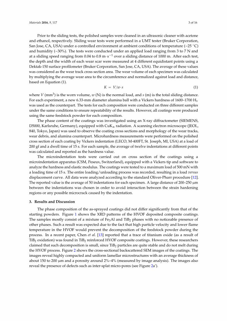
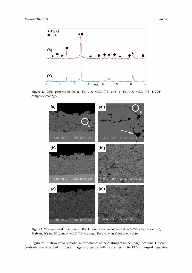
The phase composition of the as-sprayed coatings did not differ significantly from that of thestarting powders. Figure 1 shows the XRD patterns of the HVOF deposited composite coatings.The samples mostly consist of a mixture of Fe3Al and TiB2 phases with no noticeable presence ofother phases. Such a result was expected due to the fact that high particle velocity and lower flametemperature in the HVOF would prevent the decomposition of the feedstock powder during theprocess. In a recent paper, Chen et al. [13] reported that a trace of titanium oxide (as a result ofTiB2 oxidation) was found in TiB2 reinforced HVOF composite coatings. However, these researchersclaimed that such decomposition is small, since TiB2 particles are quite stable and do not melt duringthe HVOF process. Figure 2 shows the cross-sectional backscattered SEM images of the coatings. Theimages reveal highly compacted and uniform lamellar microstructures with an average thickness ofabout 150 to 200 µm and a porosity around 2%–4% (measured by image analysis). The images alsoreveal the presence of defects such as inter-splat micro-pores (see Figure 2a’).
Materials 2016, 9, 117 4 of 16Materials 2016, 9, 117 4 of 15
4
Figure 1. XRD patterns of the (a) Fe3Al‐30 vol.% TiB2 and (b) Fe3Al‐50 vol.% TiB2 HVOF composite coatings.
Figure 2. Cross‐sectional backscattered SEM images of the unreinforced (0 vol.% TiB2) Fe3Al (a and a’),
30 (b and b’) and 50 (c and c’) vol.% TiB2 coatings. The arrow on a’ indicates a pore.
Figure 2a’–c’ show cross‐sectional morphologies of the coatings at higher magnifications.
Different contrasts are observed in these images alongside with porosities. The EDS
(Energy‐Dispersive Spectroscopy) patterns of each region are shown in Figure 3. According to these
EDS patterns, the dark grey regions (a sample of which is indicated by B in Figure 2a’), encountered
at the splat boundaries, are rich in oxygen and therefore correspond most likely to oxide inclusions
Figure 1. XRD patterns of the (a) Fe3Al-30 vol.% TiB2 and (b) Fe3Al-50 vol.% TiB2 HVOFcomposite coatings.
Materials 2016, 9, 117 4 of 15
4
Figure 1. XRD patterns of the (a) Fe3Al‐30 vol.% TiB2 and (b) Fe3Al‐50 vol.% TiB2 HVOF composite coatings.
Figure 2. Cross‐sectional backscattered SEM images of the unreinforced (0 vol.% TiB2) Fe3Al (a and a’),
30 (b and b’) and 50 (c and c’) vol.% TiB2 coatings. The arrow on a’ indicates a pore.
Figure 2a’–c’ show cross‐sectional morphologies of the coatings at higher magnifications.
Different contrasts are observed in these images alongside with porosities. The EDS
(Energy‐Dispersive Spectroscopy) patterns of each region are shown in Figure 3. According to these
EDS patterns, the dark grey regions (a sample of which is indicated by B in Figure 2a’), encountered
at the splat boundaries, are rich in oxygen and therefore correspond most likely to oxide inclusions
Figure 2. Cross-sectional backscattered SEM images of the unreinforced (0 vol.% TiB2) Fe3Al (a and a’),30 (b and b’) and 50 (c and c’) vol.% TiB2 coatings. The arrow on a’ indicates a pore.
Figure 2a’–c’ show cross-sectional morphologies of the coatings at higher magnifications. Differentcontrasts are observed in these images alongside with porosities. The EDS (Energy-Dispersive
Materials 2016, 9, 117 5 of 16
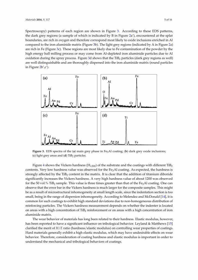
Spectroscopy) patterns of each region are shown in Figure 3. According to these EDS patterns,the dark grey regions (a sample of which is indicated by B in Figure 2a’), encountered at the splatboundaries, are rich in oxygen and therefore correspond most likely to oxide inclusions enriched in Alcompared to the iron aluminide matrix (Figure 3b). The light grey regions (indicated by A in Figure 2a)are rich in Fe (Figure 3c). These regions are most likely due to Fe contamination of the powder by thehigh energy ball milling process or may come from Al-depleted iron aluminide particles due to Aloxidation during the spray process. Figure 3d shows that the TiB2 particles (dark grey regions as well)are well distinguishable and are thoroughly dispersed into the iron aluminide matrix (round particlesin Figure 2b’,c’).
Materials 2016, 9, 117 5 of 15
5
enriched in Al compared to the iron aluminide matrix (Figure 3b). The light grey regions (indicated
by A in Figure 2a) are rich in Fe (Figure 3c). These regions are most likely due to Fe contamination of
the powder by the high energy ball milling process or may come from Al‐depleted iron aluminide
particles due to Al oxidation during the spray process. Figure 3d shows that the TiB2 particles
(dark grey regions as well) are well distinguishable and are thoroughly dispersed into the iron
aluminide matrix (round particles in Figure 2b’,c’).
Figure 3. EDS spectra of the (a) main grey phase in Fe3Al coating, (b) dark grey oxide inclusions,
(c) light grey areas and (d) TiB2 particles.
Figure 4 shows the Vickers hardness (Hv200) of the substrate and the coatings with different TiB2
contents. Very low hardness value was observed for the Fe3Al coating. As expected, the hardness is
strongly affected by the TiB2 content in the matrix. It is clear that the addition of titanium diboride
significantly increases the Vickers hardness. A very high hardness value of about 1200 was observed
for the 50 vol.% TiB2 sample. This value is three times greater than that of the Fe3Al coating. One can
observe that the error bar in the Vickers hardness is much larger for the composite samples. This
might be as a result of microstructural inhomogeneity at small length scale, since the indentation
section is too small, being in the range of dispersion inhomogeneity. According to Melendez and
McDonald [14], it is common for such coatings to exhibit high standard deviations due to
non‐homogeneous distribution of reinforcing particles. The Vickers hardness measurement depends
on whether the indenter is located on areas with a high concentration of TiB2 reinforcement or on
areas with a high concentration of iron aluminide matrix.
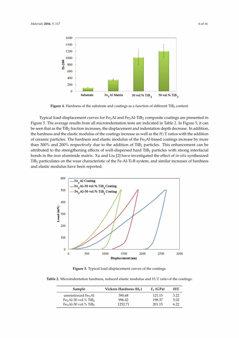
Figure 4. Hardness of the substrate and coatings as a function of different TiB2 content.
Figure 3. EDS spectra of the (a) main grey phase in Fe3Al coating; (b) dark grey oxide inclusions;(c) light grey areas and (d) TiB2 particles.
Figure 4 shows the Vickers hardness (Hv200) of the substrate and the coatings with different TiB2
contents. Very low hardness value was observed for the Fe3Al coating. As expected, the hardness isstrongly affected by the TiB2 content in the matrix. It is clear that the addition of titanium diboridesignificantly increases the Vickers hardness. A very high hardness value of about 1200 was observedfor the 50 vol.% TiB2 sample. This value is three times greater than that of the Fe3Al coating. One canobserve that the error bar in the Vickers hardness is much larger for the composite samples. This mightbe as a result of microstructural inhomogeneity at small length scale, since the indentation section is toosmall, being in the range of dispersion inhomogeneity. According to Melendez and McDonald [14], it iscommon for such coatings to exhibit high standard deviations due to non-homogeneous distribution ofreinforcing particles. The Vickers hardness measurement depends on whether the indenter is locatedon areas with a high concentration of TiB2 reinforcement or on areas with a high concentration of ironaluminide matrix.
The wear behavior of materials has long been related to their hardness. Elastic modulus, however,has been reported to have a significant influence on tribological behavior. Leyland & Matthews [15]clarified the merit of H/E ratio (hardness/elastic modulus) on controlling wear properties of coatings.Hard materials generally exhibit a high elastic modulus, which may have undesirable effects on wearbehavior. Therefore, consideration of coating hardness and elastic modulus is important in order tounderstand the mechanical and tribological behaviors of coatings.
Materials 2016, 9, 117 6 of 16
Materials 2016, 9, 117 5 of 15
5
enriched in Al compared to the iron aluminide matrix (Figure 3b). The light grey regions (indicated
by A in Figure 2a) are rich in Fe (Figure 3c). These regions are most likely due to Fe contamination of
the powder by the high energy ball milling process or may come from Al‐depleted iron aluminide
particles due to Al oxidation during the spray process. Figure 3d shows that the TiB2 particles
(dark grey regions as well) are well distinguishable and are thoroughly dispersed into the iron
aluminide matrix (round particles in Figure 2b’,c’).
Figure 3. EDS spectra of the (a) main grey phase in Fe3Al coating, (b) dark grey oxide inclusions,
(c) light grey areas and (d) TiB2 particles.
Figure 4 shows the Vickers hardness (Hv200) of the substrate and the coatings with different TiB2
contents. Very low hardness value was observed for the Fe3Al coating. As expected, the hardness is
strongly affected by the TiB2 content in the matrix. It is clear that the addition of titanium diboride
significantly increases the Vickers hardness. A very high hardness value of about 1200 was observed
for the 50 vol.% TiB2 sample. This value is three times greater than that of the Fe3Al coating. One can
observe that the error bar in the Vickers hardness is much larger for the composite samples. This
might be as a result of microstructural inhomogeneity at small length scale, since the indentation
section is too small, being in the range of dispersion inhomogeneity. According to Melendez and
McDonald [14], it is common for such coatings to exhibit high standard deviations due to
non‐homogeneous distribution of reinforcing particles. The Vickers hardness measurement depends
on whether the indenter is located on areas with a high concentration of TiB2 reinforcement or on
areas with a high concentration of iron aluminide matrix.
Figure 4. Hardness of the substrate and coatings as a function of different TiB2 content. Figure 4. Hardness of the substrate and coatings as a function of different TiB2 content.
Typical load-displacement curves for Fe3Al and Fe3Al-TiB2 composite coatings are presented inFigure 5. The average results from all microindentation tests are indicated in Table 2. In Figure 5, it canbe seen that as the TiB2 fraction increases, the displacement and indentation depth decrease. In addition,the hardness and the elastic modulus of the coatings increase as well as the H/E ratios with the additionof ceramic particles. The hardness and elastic modulus of the Fe3Al-based coatings increase by morethan 300% and 200% respectively due to the addition of TiB2 particles. This enhancement can beattributed to the strengthening effects of well-dispersed hard TiB2 particles with strong interfacialbonds in the iron aluminide matrix. Xu and Liu [2] have investigated the effect of in-situ synthesizedTiB2 particulates on the wear characteristic of the Fe-Al-Ti-B system, and similar increases of hardnessand elastic modulus have been reported.
Materials 2016, 9, 117 6 of 15
6
The wear behavior of materials has long been related to their hardness. Elastic modulus,
however, has been reported to have a significant influence on tribological behavior. Leyland &
Matthews [15] clarified the merit of H/E ratio (hardness/elastic modulus) on controlling wear
properties of coatings. Hard materials generally exhibit a high elastic modulus, which may have
undesirable effects on wear behavior. Therefore, consideration of coating hardness and elastic
modulus is important in order to understand the mechanical and tribological behaviors of coatings.
Typical load‐displacement curves for Fe3Al and Fe3Al‐TiB2 composite coatings are presented in
Figure 5. The average results from all microindentation tests are indicated in Table 2. In Figure 5,
it can be seen that as the TiB2 fraction increases, the displacement and indentation depth decrease.
In addition, the hardness and the elastic modulus of the coatings increase as well as the H/E ratios
with the addition of ceramic particles. The hardness and elastic modulus of the Fe3Al‐based coatings
increase by more than 300% and 200% respectively due to the addition of TiB2 particles. This
enhancement can be attributed to the strengthening effects of well‐dispersed hard TiB2 particles with
strong interfacial bonds in the iron aluminide matrix. Xu and Liu [2] have investigated the effect of
in‐situ synthesized TiB2 particulates on the wear characteristic of the Fe‐Al‐Ti‐B system, and similar
increases of hardness and elastic modulus have been reported.
Figure 5. Typical load‐displacement curves of the coatings.
Table 2. Microindentation hardness, reduced elastic modulus and H/E ratio of the coatings.
Sample Vickers Hardness (Hv) Er (GPa) H/E
unreinforced Fe3Al 390.68 121.15 3.22
Fe3Al‐30 vol.% TiB2 996.42 198.37 5.02
Fe3Al‐50 vol.% TiB2 1252.71 201.15 6.22
In thermal sprayed coatings, the preferential propagation path of cracks is mostly parallel to the
substrate [16,17]. SEM images in Figure 6 show the crack propagation in a cross section of coatings
due to Vickers indentations. In Fe3Al, cracks propagate along the weak inter‐splat interfaces. The
crack in Figure 6a for the Fe3Al appears to be quite long (>100 μm) compared to those observed in
the composite specimens (Figure 6b,c). Crack deflections as a result of the presence of TiB2 particles
may be a reason for the enhancement of the mechanical properties of such composite materials.
Figure 5. Typical load-displacement curves of the coatings.
Table 2. Microindentation hardness, reduced elastic modulus and H/E ratio of the coatings.
Sample Vickers Hardness (Hv) Er (GPa) H/E
unreinforced Fe3Al 390.68 121.15 3.22Fe3Al-30 vol.% TiB2 996.42 198.37 5.02Fe3Al-50 vol.% TiB2 1252.71 201.15 6.22
Materials 2016, 9, 117 7 of 16
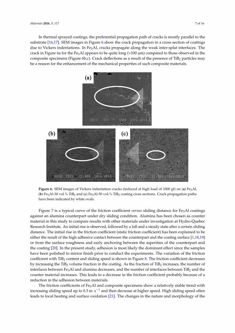
In thermal sprayed coatings, the preferential propagation path of cracks is mostly parallel to thesubstrate [16,17]. SEM images in Figure 6 show the crack propagation in a cross section of coatingsdue to Vickers indentations. In Fe3Al, cracks propagate along the weak inter-splat interfaces. Thecrack in Figure 6a for the Fe3Al appears to be quite long (>100 µm) compared to those observed in thecomposite specimens (Figure 6b,c). Crack deflections as a result of the presence of TiB2 particles maybe a reason for the enhancement of the mechanical properties of such composite materials.Materials 2016, 9, 117 7 of 15
7
Figure 6. SEM images of Vickers indentation cracks (induced at high load of 1000 gf) on (a) Fe3Al,
(b) Fe3Al‐30 vol.% TiB2 and (c) Fe3Al‐50 vol.% TiB2 coating cross sections. Crack propagation paths
have been indicated by white ovals.
Figure 7 is a typical curve of the friction coefficient versus sliding distance for Fe3Al coatings
against an alumina counterpart under dry sliding condition. Alumina has been chosen as counter
material in this study to compare results with other materials under investigation at Hydro‐Quebec
Research Institute. An initial rise is observed, followed by a fall and a steady state after a certain
sliding distance. The initial rise in the friction coefficient (static friction coefficient) has been
explained to be either the result of the high adhesive contact between the counterpart and the
coating surface [1,18,19] or from the surface roughness and early anchoring between the asperities of
the counterpart and the coating [20]. In the present study, adhesion is most likely the dominant
effect since the samples have been polished to mirror finish prior to conduct the experiments. The
variation of the friction coefficient with TiB2 content and sliding speed is shown in Figure 8. The
friction coefficient decreases by increasing the TiB2 volume fraction in the coating. As the fraction of
TiB2 increases, the number of interfaces between Fe3Al and alumina decreases, and the number of
interfaces between TiB2 and the counter material increases. This leads to a decrease in the friction
coefficient probably because of a reduction in the adhesion between materials.
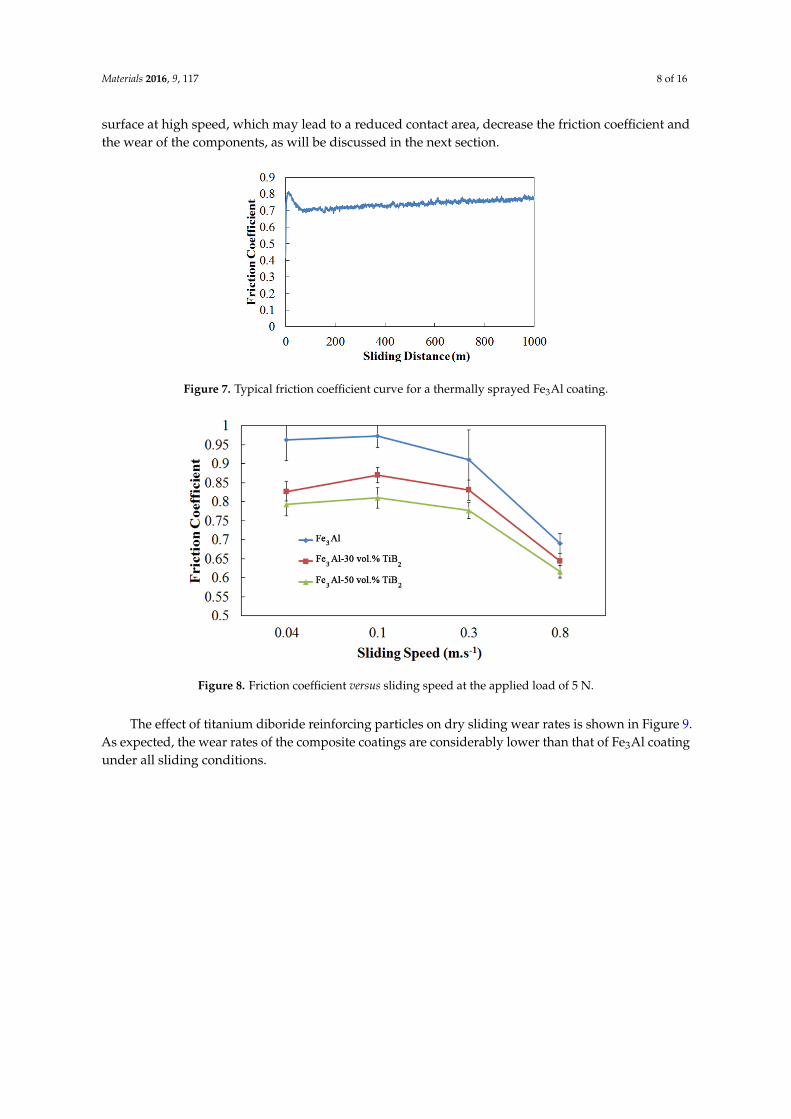
Figure 7. Typical friction coefficient curve for a thermally sprayed Fe3Al coating.
Figure 6. SEM images of Vickers indentation cracks (induced at high load of 1000 gf) on (a) Fe3Al,(b) Fe3Al-30 vol.% TiB2 and (c) Fe3Al-50 vol.% TiB2 coating cross sections. Crack propagation pathshave been indicated by white ovals.
Figure 7 is a typical curve of the friction coefficient versus sliding distance for Fe3Al coatingsagainst an alumina counterpart under dry sliding condition. Alumina has been chosen as countermaterial in this study to compare results with other materials under investigation at Hydro-QuebecResearch Institute. An initial rise is observed, followed by a fall and a steady state after a certain slidingdistance. The initial rise in the friction coefficient (static friction coefficient) has been explained to beeither the result of the high adhesive contact between the counterpart and the coating surface [1,18,19]or from the surface roughness and early anchoring between the asperities of the counterpart andthe coating [20]. In the present study, adhesion is most likely the dominant effect since the sampleshave been polished to mirror finish prior to conduct the experiments. The variation of the frictioncoefficient with TiB2 content and sliding speed is shown in Figure 8. The friction coefficient decreasesby increasing the TiB2 volume fraction in the coating. As the fraction of TiB2 increases, the number ofinterfaces between Fe3Al and alumina decreases, and the number of interfaces between TiB2 and thecounter material increases. This leads to a decrease in the friction coefficient probably because of areduction in the adhesion between materials.
The friction coefficients of Fe3Al and composite specimens show a relatively stable trend withincreasing sliding speed up to 0.3 m¨ s´1 and then decrease at higher speed. High sliding speed oftenleads to local heating and surface oxidation [21]. The changes in the nature and morphology of the
Materials 2016, 9, 117 8 of 16
surface at high speed, which may lead to a reduced contact area, decrease the friction coefficient andthe wear of the components, as will be discussed in the next section.
Materials 2016, 9, 117 7 of 15
7
Figure 6. SEM images of Vickers indentation cracks (induced at high load of 1000 gf) on (a) Fe3Al,
(b) Fe3Al‐30 vol.% TiB2 and (c) Fe3Al‐50 vol.% TiB2 coating cross sections. Crack propagation paths
have been indicated by white ovals.
Figure 7 is a typical curve of the friction coefficient versus sliding distance for Fe3Al coatings
against an alumina counterpart under dry sliding condition. Alumina has been chosen as counter
material in this study to compare results with other materials under investigation at Hydro‐Quebec
Research Institute. An initial rise is observed, followed by a fall and a steady state after a certain
sliding distance. The initial rise in the friction coefficient (static friction coefficient) has been
explained to be either the result of the high adhesive contact between the counterpart and the
coating surface [1,18,19] or from the surface roughness and early anchoring between the asperities of
the counterpart and the coating [20]. In the present study, adhesion is most likely the dominant
effect since the samples have been polished to mirror finish prior to conduct the experiments. The
variation of the friction coefficient with TiB2 content and sliding speed is shown in Figure 8. The
friction coefficient decreases by increasing the TiB2 volume fraction in the coating. As the fraction of
TiB2 increases, the number of interfaces between Fe3Al and alumina decreases, and the number of
interfaces between TiB2 and the counter material increases. This leads to a decrease in the friction
coefficient probably because of a reduction in the adhesion between materials.
Figure 7. Typical friction coefficient curve for a thermally sprayed Fe3Al coating. Figure 7. Typical friction coefficient curve for a thermally sprayed Fe3Al coating.
Materials 2016, 9, 117 8 of 15
8
Figure 8. Friction coefficient versus sliding speed at the applied load of 5 N.
The friction coefficients of Fe3Al and composite specimens show a relatively stable trend with
increasing sliding speed up to 0.3 m s−1 and then decrease at higher speed. High sliding speed often
leads to local heating and surface oxidation [21]. The changes in the nature and morphology of the
surface at high speed, which may lead to a reduced contact area, decrease the friction coefficient and
the wear of the components, as will be discussed in the next section.
The effect of titanium diboride reinforcing particles on dry sliding wear rates is shown in Figure
9. As expected, the wear rates of the composite coatings are considerably lower than that of Fe3Al
coating under all sliding conditions.
Figure 9. Wear rates as a function of sliding speed and applied load. (a) Fe3Al coatings and (b–d)
composite coatings.
The wear rate of the Fe3Al coatings is on the order of 10−3 to 10−4 mm3 N−1 m−1. On the other hand,
the wear rates of the 50 vol.% TiB2 coating is 1 to 3 orders of magnitude lower. This improvement is
attributed to the increase in Vickers hardness and H/E values, caused by the presence of TiB2
particles, and is in agreement with Archard’s law, which relates wear of materials to hardness [22].
Figure 8. Friction coefficient versus sliding speed at the applied load of 5 N.
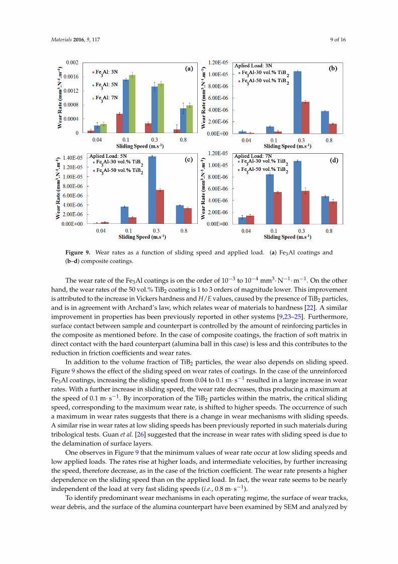
The effect of titanium diboride reinforcing particles on dry sliding wear rates is shown in Figure 9.As expected, the wear rates of the composite coatings are considerably lower than that of Fe3Al coatingunder all sliding conditions.
Materials 2016, 9, 117 9 of 16
Materials 2016, 9, 117 8 of 15
8
Figure 8. Friction coefficient versus sliding speed at the applied load of 5 N.
The friction coefficients of Fe3Al and composite specimens show a relatively stable trend with
increasing sliding speed up to 0.3 m s−1 and then decrease at higher speed. High sliding speed often
leads to local heating and surface oxidation [21]. The changes in the nature and morphology of the
surface at high speed, which may lead to a reduced contact area, decrease the friction coefficient and
the wear of the components, as will be discussed in the next section.
The effect of titanium diboride reinforcing particles on dry sliding wear rates is shown in Figure
9. As expected, the wear rates of the composite coatings are considerably lower than that of Fe3Al
coating under all sliding conditions.
Figure 9. Wear rates as a function of sliding speed and applied load. (a) Fe3Al coatings and (b–d)
composite coatings.
The wear rate of the Fe3Al coatings is on the order of 10−3 to 10−4 mm3 N−1 m−1. On the other hand,
the wear rates of the 50 vol.% TiB2 coating is 1 to 3 orders of magnitude lower. This improvement is
attributed to the increase in Vickers hardness and H/E values, caused by the presence of TiB2
particles, and is in agreement with Archard’s law, which relates wear of materials to hardness [22].
Figure 9. Wear rates as a function of sliding speed and applied load. (a) Fe3Al coatings and(b–d) composite coatings.
The wear rate of the Fe3Al coatings is on the order of 10´3 to 10´4 mm3¨N´1¨m´1. On the otherhand, the wear rates of the 50 vol.% TiB2 coating is 1 to 3 orders of magnitude lower. This improvementis attributed to the increase in Vickers hardness and H/E values, caused by the presence of TiB2 particles,and is in agreement with Archard’s law, which relates wear of materials to hardness [22]. A similarimprovement in properties has been previously reported in other systems [9,23–25]. Furthermore,surface contact between sample and counterpart is controlled by the amount of reinforcing particles inthe composite as mentioned before. In the case of composite coatings, the fraction of soft matrix indirect contact with the hard counterpart (alumina ball in this case) is less and this contributes to thereduction in friction coefficients and wear rates.
In addition to the volume fraction of TiB2 particles, the wear also depends on sliding speed.Figure 9 shows the effect of the sliding speed on wear rates of coatings. In the case of the unreinforcedFe3Al coatings, increasing the sliding speed from 0.04 to 0.1 m¨ s´1 resulted in a large increase in wearrates. With a further increase in sliding speed, the wear rate decreases, thus producing a maximum atthe speed of 0.1 m¨ s´1. By incorporation of the TiB2 particles within the matrix, the critical slidingspeed, corresponding to the maximum wear rate, is shifted to higher speeds. The occurrence of sucha maximum in wear rates suggests that there is a change in wear mechanisms with sliding speeds.A similar rise in wear rates at low sliding speeds has been previously reported in such materials duringtribological tests. Guan et al. [26] suggested that the increase in wear rates with sliding speed is due tothe delamination of surface layers.
One observes in Figure 9 that the minimum values of wear rate occur at low sliding speeds andlow applied loads. The rates rise at higher loads, and intermediate velocities, by further increasingthe speed, therefore decrease, as in the case of the friction coefficient. The wear rate presents a higherdependence on the sliding speed than on the applied load. In fact, the wear rate seems to be nearlyindependent of the load at very fast sliding speeds (i.e., 0.8 m¨ s´1).
To identify predominant wear mechanisms in each operating regime, the surface of wear tracks,wear debris, and the surface of the alumina counterpart have been examined by SEM and analyzed by
Materials 2016, 9, 117 10 of 16
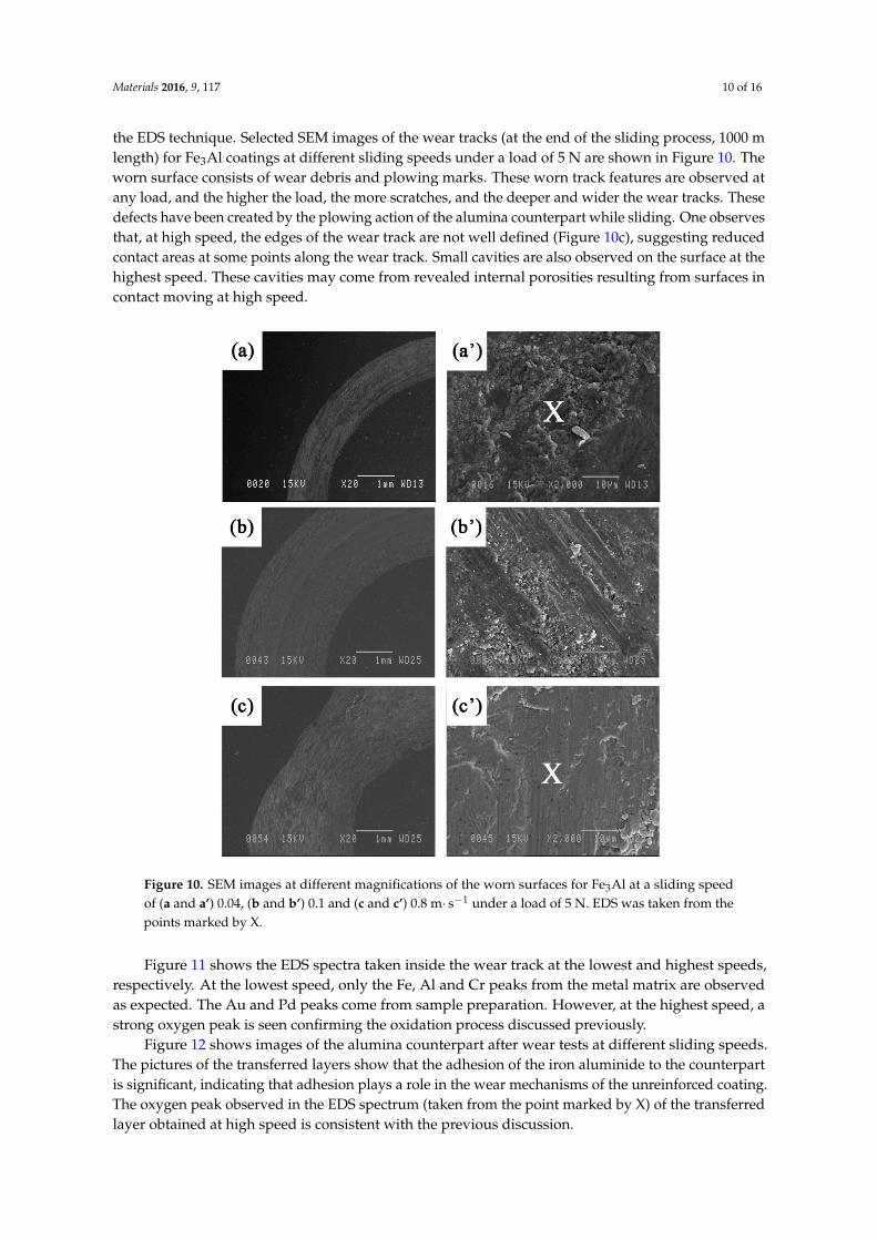
the EDS technique. Selected SEM images of the wear tracks (at the end of the sliding process, 1000 mlength) for Fe3Al coatings at different sliding speeds under a load of 5 N are shown in Figure 10. Theworn surface consists of wear debris and plowing marks. These worn track features are observed atany load, and the higher the load, the more scratches, and the deeper and wider the wear tracks. Thesedefects have been created by the plowing action of the alumina counterpart while sliding. One observesthat, at high speed, the edges of the wear track are not well defined (Figure 10c), suggesting reducedcontact areas at some points along the wear track. Small cavities are also observed on the surface at thehighest speed. These cavities may come from revealed internal porosities resulting from surfaces incontact moving at high speed.
Materials 2016, 9, 117 9 of 15
9
A similar improvement in properties has been previously reported in other systems [9,23–25].
Furthermore, surface contact between sample and counterpart is controlled by the amount of
reinforcing particles in the composite as mentioned before. In the case of composite coatings, the
fraction of soft matrix in direct contact with the hard counterpart (alumina ball in this case) is less
and this contributes to the reduction in friction coefficients and wear rates.
In addition to the volume fraction of TiB2 particles, the wear also depends on sliding speed.
Figure 9 shows the effect of the sliding speed on wear rates of coatings. In the case of the
unreinforced Fe3Al coatings, increasing the sliding speed from 0.04 to 0.1 m s−1 resulted in a large
increase in wear rates. With a further increase in sliding speed, the wear rate decreases, thus
producing a maximum at the speed of 0.1 m s−1. By incorporation of the TiB2 particles within the
matrix, the critical sliding speed, corresponding to the maximum wear rate, is shifted to higher
speeds. The occurrence of such a maximum in wear rates suggests that there is a change in wear
mechanisms with sliding speeds. A similar rise in wear rates at low sliding speeds has been
previously reported in such materials during tribological tests. Guan et al. [26] suggested that the
increase in wear rates with sliding speed is due to the delamination of surface layers.
One observes in Figure 9 that the minimum values of wear rate occur at low sliding speeds and
low applied loads. The rates rise at higher loads, and intermediate velocities, by further increasing
the speed, therefore decrease, as in the case of the friction coefficient. The wear rate presents a higher
dependence on the sliding speed than on the applied load. In fact, the wear rate seems to be nearly
independent of the load at very fast sliding speeds (i.e., 0.8 m s−1).
To identify predominant wear mechanisms in each operating regime, the surface of wear tracks,
wear debris, and the surface of the alumina counterpart have been examined by SEM and analyzed
by the EDS technique. Selected SEM images of the wear tracks (at the end of the sliding process, 1000
m length) for Fe3Al coatings at different sliding speeds under a load of 5 N are shown in Figure 10.
The worn surface consists of wear debris and plowing marks. These worn track features are
observed at any load, and the higher the load, the more scratches, and the deeper and wider the
wear tracks. These defects have been created by the plowing action of the alumina counterpart while
sliding. One observes that, at high speed, the edges of the wear track are not well defined (Figure
10c), suggesting reduced contact areas at some points along the wear track. Small cavities are also
observed on the surface at the highest speed. These cavities may come from revealed internal
porosities resulting from surfaces in contact moving at high speed.
Materials 2016, 9, 117 10 of 15
10
Figure 10. SEM images at different magnifications of the worn surfaces for Fe3Al at a sliding speed of
(a and a’) 0.04, (b and b’) 0.1 and (c and c’) 0.8 m s−1 under a load of 5 N. EDS was taken from the
points marked by X.
Figure 11 shows the EDS spectra taken inside the wear track at the lowest and highest speeds,
respectively. At the lowest speed, only the Fe, Al and Cr peaks from the metal matrix are observed as
expected. The Au and Pd peaks come from sample preparation. However, at the highest speed,
a strong oxygen peak is seen confirming the oxidation process discussed previously.
Figure 11. EDS spectra of the worn surface of Fe3Al coating at (a) 0.04 and (b) 0.8 m s−1.
Figure 12 shows images of the alumina counterpart after wear tests at different sliding speeds.
The pictures of the transferred layers show that the adhesion of the iron aluminide to the counterpart
is significant, indicating that adhesion plays a role in the wear mechanisms of the unreinforced
coating. The oxygen peak observed in the EDS spectrum (taken from the point marked by X) of the
transferred layer obtained at high speed is consistent with the previous discussion.
Figure 10. SEM images at different magnifications of the worn surfaces for Fe3Al at a sliding speedof (a and a’) 0.04, (b and b’) 0.1 and (c and c’) 0.8 m¨ s´1 under a load of 5 N. EDS was taken from thepoints marked by X.
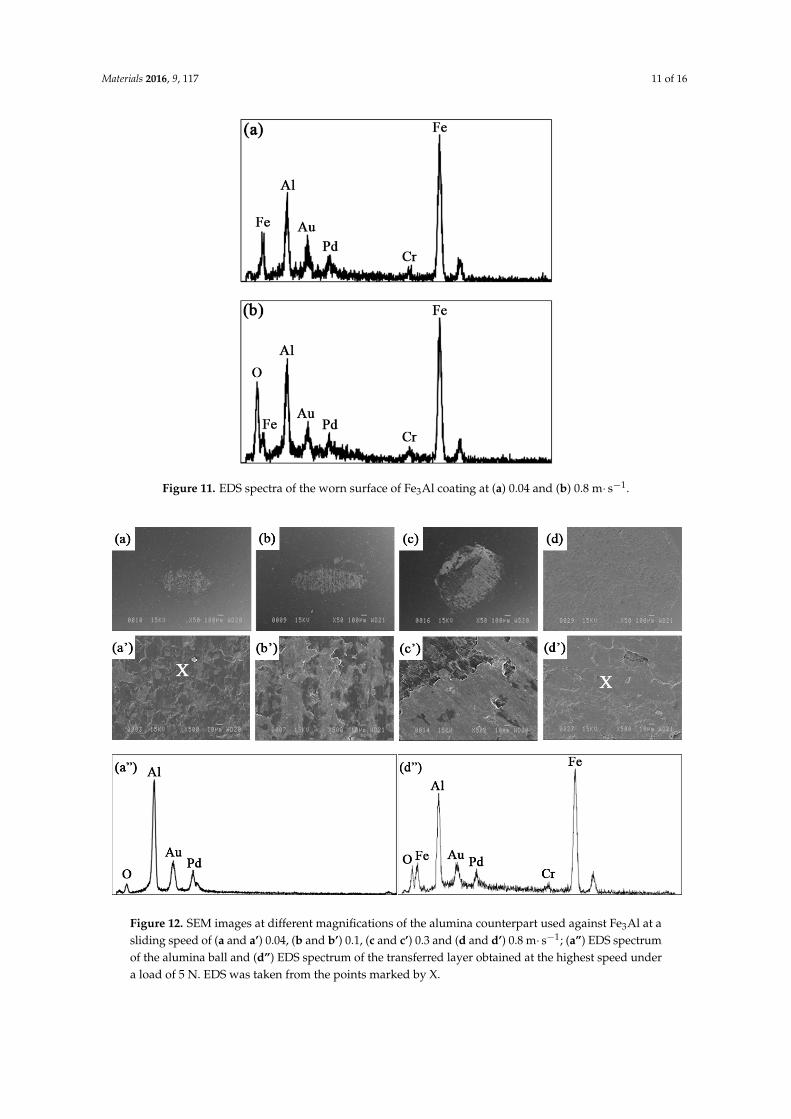
Figure 11 shows the EDS spectra taken inside the wear track at the lowest and highest speeds,respectively. At the lowest speed, only the Fe, Al and Cr peaks from the metal matrix are observedas expected. The Au and Pd peaks come from sample preparation. However, at the highest speed, astrong oxygen peak is seen confirming the oxidation process discussed previously.
Figure 12 shows images of the alumina counterpart after wear tests at different sliding speeds.The pictures of the transferred layers show that the adhesion of the iron aluminide to the counterpartis significant, indicating that adhesion plays a role in the wear mechanisms of the unreinforced coating.The oxygen peak observed in the EDS spectrum (taken from the point marked by X) of the transferredlayer obtained at high speed is consistent with the previous discussion.
Materials 2016, 9, 117 11 of 16
Materials 2016, 9, 117 10 of 15
10
Figure 10. SEM images at different magnifications of the worn surfaces for Fe3Al at a sliding speed of
(a and a’) 0.04, (b and b’) 0.1 and (c and c’) 0.8 m s−1 under a load of 5 N. EDS was taken from the
points marked by X.
Figure 11 shows the EDS spectra taken inside the wear track at the lowest and highest speeds,
respectively. At the lowest speed, only the Fe, Al and Cr peaks from the metal matrix are observed as
expected. The Au and Pd peaks come from sample preparation. However, at the highest speed,
a strong oxygen peak is seen confirming the oxidation process discussed previously.
Figure 11. EDS spectra of the worn surface of Fe3Al coating at (a) 0.04 and (b) 0.8 m s−1.
Figure 12 shows images of the alumina counterpart after wear tests at different sliding speeds.
The pictures of the transferred layers show that the adhesion of the iron aluminide to the counterpart
is significant, indicating that adhesion plays a role in the wear mechanisms of the unreinforced
coating. The oxygen peak observed in the EDS spectrum (taken from the point marked by X) of the
transferred layer obtained at high speed is consistent with the previous discussion.
Figure 11. EDS spectra of the worn surface of Fe3Al coating at (a) 0.04 and (b) 0.8 m¨ s´1.Materials 2016, 9, 117 11 of 15
11
Figure 12. SEM images at different magnifications of the alumina counterpart used against Fe3Al at a
sliding speed of (a and a’) 0.04, (b and b’) 0.1, (c and c’) 0.3 and (d and d’) 0.8 m s−1; (a”) EDS spectrum
of the alumina ball and (d”) EDS spectrum of the transferred layer obtained at the highest speed
under a load of 5 N. EDS was taken from the points marked by X.
Wang et al. [21] have calculated an increase of 200 °C in the interfacial temperature when the
sliding speed reaches 0.39 m s−1. Yang et al. [27] reported that the wear resistance is improved in
some systems at high sliding speed because of the formation of an oxide layer. The partially oxidized
transferred layer shown in Figure 12d’,d” may act as a lubricant and lead to a reduction of the
friction coefficient and wear rate at high speed.
As shown in Figure 4 and Table 2, the microhardness and H/E ratio of Fe3Al are relatively low.
Therefore, during the sliding wear of Fe3Al, soft material is easily removed because of adhesion and
the plowing action of the hard counterpart. As the speed increases, the loading cycle increases and
fatigue wear becomes the dominant wear mechanism [27]. Cracks are generated and propagate along
inter‐splat boundaries, as in the case shown in Figure 6a. This leads to delamination of the coating.
Pictures of the wear tracks of the composite coatings are shown in Figure 13 at speeds of
0.04–0.8 m s−1 under the same load of 5 N. No significant wear was found on the surface of the
coating when sliding at very low speed (0.04 m s−1). Figure 13b,c show the worn surface at
intermediate speeds. The presence of delamination is observed especially in Figure 13c’. SEM
analyses of the wear debris (Figure 14) show that the debris at low sliding speed (0.04 m s−1) look like
fine particles, while flakes are also observed at higher speed (0.3 m s−1) when maximum wear takes
place. It is likely that these flakes peel off from the surface following fatigue cycles. The particles and
flake‐like debris are similar to those observed by Xu et al. [1] in the Fe‐Al and Fe‐Al/WC thermally
sprayed coating. Very small cavities are also observed at high magnification in Figure 13. In this
case, in addition to internal porosities, the cavities probably come from hard particle removal from
the soft iron aluminide intermetallic matrix surface that binds the reinforcing agent. This leads to the
formation of debris shown in Figure 14a. These particles certainly act as a third body during wear;
therefore, abrasive wear also plays an important role in the case of the composite coatings. Similar
findings were observed in the case of the Fe3Al‐TiC system studied by the authors recently [11].
As before, increasing the sliding speed promotes the increase of temperature at the interface,
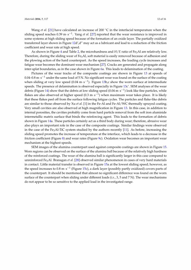
Figure 12. SEM images at different magnifications of the alumina counterpart used against Fe3Al at asliding speed of (a and a’) 0.04, (b and b’) 0.1, (c and c’) 0.3 and (d and d’) 0.8 m¨ s´1; (a”) EDS spectrumof the alumina ball and (d”) EDS spectrum of the transferred layer obtained at the highest speed undera load of 5 N. EDS was taken from the points marked by X.
Materials 2016, 9, 117 12 of 16
Wang et al. [21] have calculated an increase of 200 ˝C in the interfacial temperature when thesliding speed reaches 0.39 m¨ s´1. Yang et al. [27] reported that the wear resistance is improved insome systems at high sliding speed because of the formation of an oxide layer. The partially oxidizedtransferred layer shown in Figure 12d’,d” may act as a lubricant and lead to a reduction of the frictioncoefficient and wear rate at high speed.
As shown in Figure 4 and Table 2, the microhardness and H/E ratio of Fe3Al are relatively low.Therefore, during the sliding wear of Fe3Al, soft material is easily removed because of adhesion andthe plowing action of the hard counterpart. As the speed increases, the loading cycle increases andfatigue wear becomes the dominant wear mechanism [27]. Cracks are generated and propagate alonginter-splat boundaries, as in the case shown in Figure 6a. This leads to delamination of the coating.
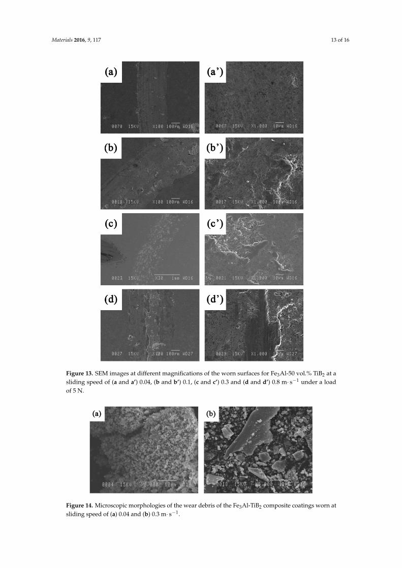
Pictures of the wear tracks of the composite coatings are shown in Figure 13 at speeds of0.04–0.8 m¨ s´1 under the same load of 5 N. No significant wear was found on the surface of the coatingwhen sliding at very low speed (0.04 m¨ s´1). Figure 13b,c show the worn surface at intermediatespeeds. The presence of delamination is observed especially in Figure 13c’. SEM analyses of the weardebris (Figure 14) show that the debris at low sliding speed (0.04 m¨ s´1) look like fine particles, whileflakes are also observed at higher speed (0.3 m¨ s´1) when maximum wear takes place. It is likelythat these flakes peel off from the surface following fatigue cycles. The particles and flake-like debrisare similar to those observed by Xu et al. [1] in the Fe-Al and Fe-Al/WC thermally sprayed coating.Very small cavities are also observed at high magnification in Figure 13. In this case, in addition tointernal porosities, the cavities probably come from hard particle removal from the soft iron aluminideintermetallic matrix surface that binds the reinforcing agent. This leads to the formation of debrisshown in Figure 14a. These particles certainly act as a third body during wear; therefore, abrasive wearalso plays an important role in the case of the composite coatings. Similar findings were observedin the case of the Fe3Al-TiC system studied by the authors recently [11]. As before, increasing thesliding speed promotes the increase of temperature at the interface, which leads to a decrease in thefriction coefficient (Figure 8) and wear rates (Figure 9c). Oxidation wear becomes an important wearmechanism at the highest speeds.
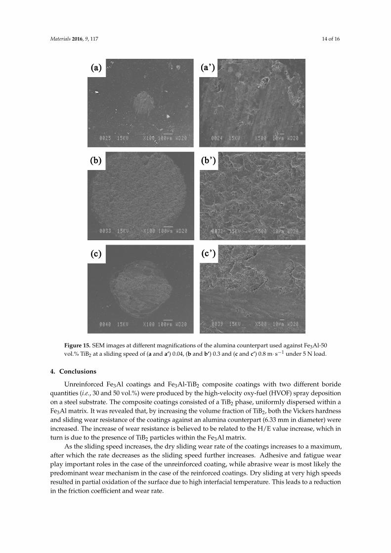
SEM images of the alumina counterpart used against composite coatings are shown in Figure 15.Worn regions can be observed on the surface of the alumina ball because of the relatively high hardnessof the reinforced coatings. The wear of the alumina ball is significantly larger in this case compared tounreinforced Fe3Al. Branagan et al. [28] observed similar phenomenon in cases of very hard materialsin contact. Little material transfer is observed in Figure 15a at the lowest sliding speed; however, asthe speed increases to 0.8 m¨ s´1 (Figure 15c), a dark layer (possibly partly oxidized) covers parts ofthe counterpart. It should be mentioned that almost no significant difference was found on the wornsurface of the counterpart when sliding under different loads (i.e., 3, 5 and 7 N). The wear mechanismsdo not appear to be so sensitive to the applied load in the investigated range.
Materials 2016, 9, 117 13 of 16
Materials 2016, 9, 117 12 of 15
12
which leads to a decrease in the friction coefficient (Figure 8) and wear rates (Figure 9c). Oxidation
wear becomes an important wear mechanism at the highest speeds.
Figure 13. SEM images at different magnifications of the worn surfaces for Fe3Al‐50 vol.% TiB2 at a
sliding speed of (a and a’) 0.04, (b and b’) 0.1, (c and c’) 0.3 and (d and d’) 0.8 m s−1 under a load of 5 N.
Figure 14. Microscopic morphologies of the wear debris of the Fe3Al‐TiB2 composite coatings worn at
sliding speed of (a) 0.04 and (b) 0.3 m s−1.
Figure 13. SEM images at different magnifications of the worn surfaces for Fe3Al-50 vol.% TiB2 at asliding speed of (a and a’) 0.04, (b and b’) 0.1, (c and c’) 0.3 and (d and d’) 0.8 m¨ s´1 under a loadof 5 N.
Materials 2016, 9, 117 12 of 15
12
which leads to a decrease in the friction coefficient (Figure 8) and wear rates (Figure 9c). Oxidation
wear becomes an important wear mechanism at the highest speeds.
Figure 13. SEM images at different magnifications of the worn surfaces for Fe3Al‐50 vol.% TiB2 at a
sliding speed of (a and a’) 0.04, (b and b’) 0.1, (c and c’) 0.3 and (d and d’) 0.8 m s−1 under a load of 5 N.
Figure 14. Microscopic morphologies of the wear debris of the Fe3Al‐TiB2 composite coatings worn at
sliding speed of (a) 0.04 and (b) 0.3 m s−1. Figure 14. Microscopic morphologies of the wear debris of the Fe3Al-TiB2 composite coatings worn atsliding speed of (a) 0.04 and (b) 0.3 m¨ s´1.
Materials 2016, 9, 117 14 of 16
Materials 2016, 9, 117 13 of 15
13
SEM images of the alumina counterpart used against composite coatings are shown in Figure 15.
Worn regions can be observed on the surface of the alumina ball because of the relatively high
hardness of the reinforced coatings. The wear of the alumina ball is significantly larger in this case
compared to unreinforced Fe3Al. Branagan et al. [28] observed similar phenomenon in cases of very
hard materials in contact. Little material transfer is observed in Figure 15a at the lowest sliding
speed; however, as the speed increases to 0.8 m s−1 (Figure 15c), a dark layer (possibly partly
oxidized) covers parts of the counterpart. It should be mentioned that almost no significant
difference was found on the worn surface of the counterpart when sliding under different loads
(i.e., 3, 5 and 7 N). The wear mechanisms do not appear to be so sensitive to the applied load in the
investigated range.
Figure 15. SEM images at different magnifications of the alumina counterpart used against Fe3Al‐50
vol.% TiB2 at a sliding speed of (a and a’) 0.04, (b and b’) 0.3 and (c and c’) 0.8 m s−1 under 5 N load.
4. Conclusions
Unreinforced Fe3Al coatings and Fe3Al‐TiB2 composite coatings with two different boride quantities
(i.e., 30 and 50 vol.%) were produced by the high‐velocity oxy‐fuel (HVOF) spray deposition on a
steel substrate. The composite coatings consisted of a TiB2 phase, uniformly dispersed within a Fe3Al
matrix. It was revealed that, by increasing the volume fraction of TiB2, both the Vickers hardness and
sliding wear resistance of the coatings against an alumina counterpart (6.33 mm in diameter) were
Figure 15. SEM images at different magnifications of the alumina counterpart used against Fe3Al-50vol.% TiB2 at a sliding speed of (a and a’) 0.04, (b and b’) 0.3 and (c and c’) 0.8 m¨ s´1 under 5 N load.
4. Conclusions
Unreinforced Fe3Al coatings and Fe3Al-TiB2 composite coatings with two different boridequantities (i.e., 30 and 50 vol.%) were produced by the high-velocity oxy-fuel (HVOF) spray depositionon a steel substrate. The composite coatings consisted of a TiB2 phase, uniformly dispersed within aFe3Al matrix. It was revealed that, by increasing the volume fraction of TiB2, both the Vickers hardnessand sliding wear resistance of the coatings against an alumina counterpart (6.33 mm in diameter) wereincreased. The increase of wear resistance is believed to be related to the H/E value increase, which inturn is due to the presence of TiB2 particles within the Fe3Al matrix.
As the sliding speed increases, the dry sliding wear rate of the coatings increases to a maximum,after which the rate decreases as the sliding speed further increases. Adhesive and fatigue wearplay important roles in the case of the unreinforced coating, while abrasive wear is most likely thepredominant wear mechanism in the case of the reinforced coatings. Dry sliding at very high speedsresulted in partial oxidation of the surface due to high interfacial temperature. This leads to a reductionin the friction coefficient and wear rate.
Materials 2016, 9, 117 15 of 16
Acknowledgments: The authors gratefully acknowledge the financial support of Hydro-Quebec, Weir CanadaInc., and the Natural Sciences and Engineering Research Council of Canada (NSERC) through the grant #451516-13.The full support from the University Laval is also greatly appreciated.
Author Contributions: Mahdi Amiriyan conducted the research under the supervision of Houshang Alamdariand Robert Schulz. Sylvio Savoie helped with the experiments. Carl Blais and Mario Gariepy made usefulcomments during the research activities.
Conflicts of Interest: The authors declare no conflict of interest.
References
1. Xu, B.; Zhu, Z.; Ma, S.; Zhang, W.; Liu, W. Sliding wear behavior of Fe–Al and Fe–Al/WC coatings preparedby high velocity arc spraying. Wear 2004, 257, 1089–1095. [CrossRef]
2. Xu, J.; Liu, W. Wear characteristic of in situ synthetic TiB2 particulate-reinforced Al matrix composite formedby laser cladding. Wear 2006, 260, 486–492. [CrossRef]
3. Blackford, J.R.; Buckley, R.A.; Jones, H.; Sellars, C.M.; McCartney, D.G.; Horlock, A.J. Spray deposition of aniron aluminide. J. Mater. Sci. 1998, 33, 4417–4421. [CrossRef]
4. Totemeier, T.; Wright, R.; Swank, W. Microstructure and stresses in HVOF sprayed iron aluminide coatings.J. Therm. Spray Technol. 2002, 11, 400–408. [CrossRef]
5. Schwetzke, R.; Kreye, H. Microstructure and properties of tungsten carbide coatings sprayed with varioushigh-velocity oxygen fuel spray systems. J. Therm. Spray Technol. 1999, 8, 433–439. [CrossRef]
6. Sidhu, T.S.; Agrawal, R.D.; Prakash, S. Hot corrosion of some superalloys and role of high-velocity oxy-fuelspray coatings—A review. Surf. Coat. Technol. 2005, 198, 441–446. [CrossRef]
7. Totemeier, T.; Wright, R.; Swank, W. Mechanical and physical properties of high-velocity oxy-fuel-sprayediron aluminide coatings. Metall. Mater. Trans. A 2003, 34, 2223–2231. [CrossRef]
8. Sidhu, T.; Prakash, S.; Agrawal, R. Studies on the properties of high-velocity oxy-fuel thermal spray coatingsfor higher temperature applications. Mater. Sci. 2005, 41, 805–823. [CrossRef]
9. Chen, Y.; Wang, H.M. Microstructure and wear resistance of laser clad TiC reinforced FeAl intermetallicmatrix composite coatings. Surf. Coat. Technol. 2003, 168, 30–36. [CrossRef]
10. Zhang, X.; Ma, J.; Yang, J.; Bi, Q.; Liu, W. Dry-sliding tribological behavior of Fe–28Al–5Cr/TiC composites.Wear 2011, 271, 881–888. [CrossRef]
11. Amiriyan, M.; Alamdari, H.D.; Blais, C.; Savoie, S.; Schulz, R.; Gariépy, M. Dry sliding wear behavior ofFe3Al and Fe3Al/TiC coatings prepared by HVOF. Wear 2015, 342, 154–162. [CrossRef]
12. Oliver, W.C.; Pharr, G.M. Measurement of hardness and elastic modulus by instrumented indentation:Advances in understanding and refinements to methodology. J. Mater. Res. 2004, 19, 3–20. [CrossRef]
13. Chen, X.; Wang, H.-T.; Ji, G.-C.; Bai, X.-B.; Fu, W. Microstructure and properties of TiB2–Ni coatings withdifferent binder phase contents deposited by HVOF spray process. Rare Met. 2015. Available online:http://link.springer.com/article/10.1007/s12598-015-0528-z#/page-1 (accessed on 9 June 2015). [CrossRef]
14. Melendez, N.; McDonald, A. Development of WC-based metal matrix composite coatings using low-pressurecold gas dynamic spraying. Surf. Coat. Technol. 2013, 214, 101–109. [CrossRef]
15. Leyland, A.; Matthews, A. On the significance of the H/E ratio in wear control: A nanocomposite coatingapproach to optimised tribological behaviour. Wear 2000, 246, 1–11. [CrossRef]
16. Bolelli, G.; Cannillo, V.; Lusvarghi, L.; Riccò, S. Mechanical and tribological properties of electrolytic hardchrome and HVOF-sprayed coatings. Surf. Coat. Technol. 2006, 200, 2995–3009. [CrossRef]
17. Bolelli, G.; Cannillo, V.; Lusvarghi, L.; Manfredini, T. Glass-alumina composite coatings by plasma spraying.Part I: Microstructural and mechanical characterization. Surf. Coat. Technol. 2006, 201, 458–473. [CrossRef]
18. Guilemany, J.M.; Cinca, N.; Fernández, J.; Sampath, S. Erosion, Abrasive, and Friction Wear Behavior of IronAluminide Coatings Sprayed by HVOF. J. Therm. Spray Technol. 2008, 17, 762–773. [CrossRef]
19. Kim, Y.-S.; Kim, Y.-H. Sliding wear behavior of Fe3Al-based alloys. Mater. Sci. Eng. A 1998, 258, 319–324.[CrossRef]
20. Amirthan, G.; Balasubramanian, M. Reciprocating sliding wear studies on Si/SiC ceramic composites.Wear 2011, 271, 1039–1049. [CrossRef]
21. Wang, J.; Xing, J.; Cao, L.; Su, W.; Gao, Y. Dry sliding wear behavior of Fe3Al alloys prepared by mechanicalalloying and plasma activated sintering. Wear 2010, 268, 473–480. [CrossRef]
Materials 2016, 9, 117 16 of 16
22. Archard, J. Contact and rubbing of flat surfaces. J. Appl. Phys. 1953, 24, 981–988. [CrossRef]23. Chen, Y.; Wang, H.M. Microstructure and wear resistance of a laser clad TiC reinforced nickel aluminides
matrix composite coating. Mater. Sci. Eng. A 2004, 368, 80–87. [CrossRef]24. Alman, D.E.; Hawk, J.A.; Tylczak, J.H.; Dogan, C.P.; Wilson, R.D. Wear of iron–aluminide intermetallic-based
alloys and composites by hard particles. Wear 2001, 251, 875–884. [CrossRef]25. Sulima, I.; Klimczyk, P.; Malczewski, P. Effect of TiB2 Particles on the Tribological Properties of Stainless
Steel Matrix Composites. Acta Metall. Sin. (Engl. Lett.) 2014, 27, 12–18. [CrossRef]26. Guan, X.; Iwasaki, K.; Kishi, K.; Yamamoto, M.; Tanaka, R. Dry sliding wear behavior of Fe–28Al and
Fe–28Al–10Ti alloys. Mater. Sci. Eng. A 2004, 366, 127–134. [CrossRef]27. Yang, J.; La, P.; Liu, W.; Xue, Q. Tribological properties of FeAl intermetallics under dry sliding. Wear 2004,
257, 104–109. [CrossRef]28. Branagan, D.J.; Swank, W.D.; Haggard, D.C.; Fincke, J.R. Wear-resistant amorphous and nanocomposite steel
coatings. Metall. Mater. Trans. A 2001, 32, 2615–2621. [CrossRef]
© 2016 by the authors; licensee MDPI, Basel, Switzerland. This article is an open accessarticle distributed under the terms and conditions of the Creative Commons by Attribution(CC-BY) license (http://creativecommons.org/licenses/by/4.0/).