
Tribhuvan International Airport Pavement Analysis Report · TRIBHUVAN INTERNATIONAL AIRPORT...
28
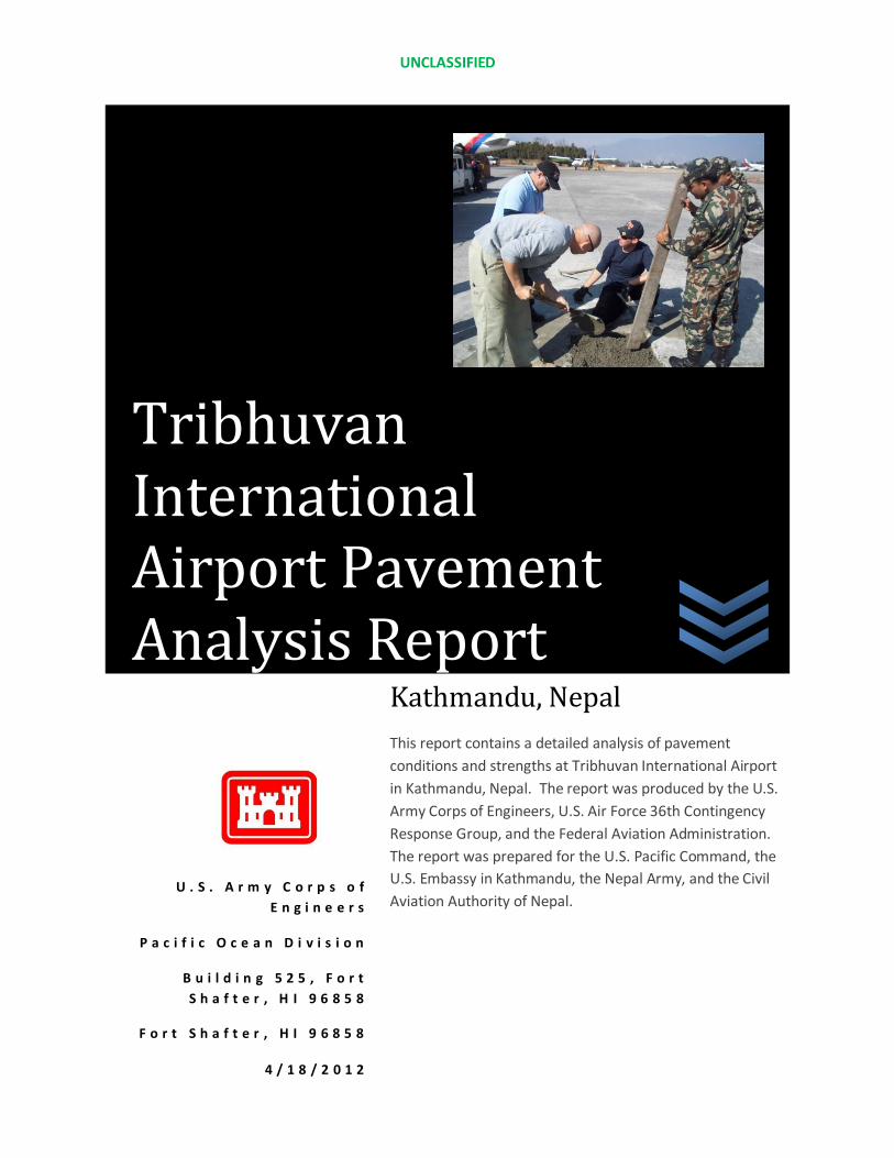
UNCLASSIFIED U.S. Army Corps of Engineers Pacific Ocean Division Building 525, Fort Shafter, HI 96858 Fort Shafter, HI 96858 4/18/2012 Kathmandu, Nepal This report contains a detailed analysis of pavement conditions and strengths at Tribhuvan International Airport in Kathmandu, Nepal. The report was produced by the U.S. Army Corps of Engineers, U.S. Air Force 36th Contingency Response Group, and the Federal Aviation Administration. The report was prepared for the U.S. Pacific Command, the U.S. Embassy in Kathmandu, the Nepal Army, and the Civil Aviation Authority of Nepal. Tribhuvan International Airport Pavement Analysis Report
Transcript of Tribhuvan International Airport Pavement Analysis Report · TRIBHUVAN INTERNATIONAL AIRPORT...
UNCLASSIFIED
U . S . A r m y C o r p s o f
E n g i n e e r s
P a c i f i c O c e a n D i v i s i o n
B u i l d i n g 5 2 5 , F o r t
S h a f t e r , H I 9 6 8 5 8
F o r t S h a f t e r , H I 9 6 8 5 8
4 / 1 8 / 2 0 1 2
Kathmandu, Nepal
This report contains a detailed analysis of pavement
conditions and strengths at Tribhuvan International Airport
in Kathmandu, Nepal. The report was produced by the U.S.
Army Corps of Engineers, U.S. Air Force 36th Contingency
Response Group, and the Federal Aviation Administration.
The report was prepared for the U.S. Pacific Command, the
U.S. Embassy in Kathmandu, the Nepal Army, and the Civil
Aviation Authority of Nepal.
Tribhuvan International Airport Pavement Analysis Report
TRIBHUVAN INTERNATIONAL AIRPORT PAVEMENT ANALYSIS FINAL REPORT
ii
Prepared by:
Tribhuvan International Airport (POC: Dr. Punya Raj Shakya - [email protected])
U.S. Air Force 36th Contingency Response Group (POC: LTC Joey Mull - [email protected])
Federal Aviation Administration (POC: Pablo Riofrio – [email protected])
U.S. Army Corps of Engineers (POC: Justin Pummell – [email protected])
TRIBHUVAN INTERNATIONAL AIRPORT PAVEMENT ANALYSIS FINAL REPORT
iii
TABLE OF CONTENTS
Executive Summary ………………………………………………………………………………………………………………………iv
Pavement Analysis Report …………………………………………………………………………………………………………… 1
Summary ………………………………………………………………………………………………………………………… 1
Restrictions/Limitations ………………………………………………………………………………………………….. 4
Observations …………………………………………………………………………………………………………………… 5
Analysis …………………………………………………………………………………………………………………………… 11
Airfield Layout ………………………………………………………………………………………………………………… 14
Recommendations ………………………………………………………………………………………………………………………. 17
Reference Documents …………………………………………………………………………………………………………………. 20

TRIBHUVAN INTERNATIONAL AIRPORT PAVEMENT ANALYSIS FINAL REPORT
iv
EXECUTIVE SUMMARY
REVIEW
In partnership with the Civil Aviation Authority of Nepal (CAAN), the Nepalese Army (NA), and the
Tribhuvan International Airport (TIA), the U.S. Army Corps of Engineers (USACE), the Federal Aviation
Administration (FAA), and the U.S. Air Force’s (USAF) 36th Contingency Response Group (CRG) conducted
a pavement condition and strength analysis of Tribhuvan International Airport in Kathmandu, Nepal.
The field testing and data collection was performed 9-20 January 2012. This report contains the final
results of that work.
The TIA pavement analysis work was performed based on recommendations from the April 2011 Seismic
Vulnerability Procedures Workshop conducted by USACE and the FAA 8-18 April 2011. Conclusions from
that workshop indicated the following efforts needed to be accomplished at TIA to determine
liquefaction potential, slope stability, and water table levels. These efforts are necessary to assess the
functionality of the airport if/when a catastrophic earthquake (> 8.4 M) affects the Kathmandu Valley.
The combined results will ultimately determine if TIA will be functional immediately after such a seismic
event occurs.
1. Geotechnical Investigation of TIA’s sub-surface features – Final report will be delivered April
2012
2. Pavement condition and strength analysis of all TIA airfield surfaces – Report contained herein
3. Retrofitting of critical facilities – Efforts will commence October 2012
4. Development of an all-hazard disaster response plan for the airfield – Draft plan will be prepared
September 2012
Based on the pavement strength and condition assessments performed by the 36th CRG, the Tribhuvan
International Airport’s main runway can withstand 100,000+ allowable passes (aircraft takeoff or
landing) over the next 2-3 years. (Please note that the number of allowable passes differs by aircraft
type. Therefore, please read the entire report to determine the total number of allowable passes per
aircraft type. A specific aircraft type may vary from the average of 100,000 passes indicated in this
executive summary.) However, if maintenance procedures and engineering recommendations are not
followed through and/or performed on a regular basis per international standards, then the number of
passes will be drastically reduced (100-1,000 allowable passes). Asphalt composition and binder to
aggregate ratio varied greatly throughout the length of the runway. Factors that could have lead to this
include poor mix design or lack thereof or materials were not available at the time of batch plant
production. This issue has led to large amounts of bleeding in certain areas.
While conducting field tests, results showed significant areas of subsurface weakness on the north side
of the domestic apron where the Nepal Army and others currently park their aircraft. It is
recommended that the U.S. Air Force and others not park or taxi on this surface during normal (non-
emergency situations). If a catastrophic earthquake were to take place, the domestic apron will most
likely not be accessible to any aircraft and will require immediate repairs to re-gain its functionality.
TRIBHUVAN INTERNATIONAL AIRPORT PAVEMENT ANALYSIS FINAL REPORT
v
In addition to strength testing, a Pavement Condition Index (PCI) was performed on all TIA airfield
surfaces. In general, the PCI ratings ranged between “Good” and “Satisfactory”. However, the airfield
surfaces have a number of common distresses, which if not monitored and maintained, could lead to
severe operational issues. Distresses found at TIA included bleeding, fatigue cracking, block cracking,
corrugation, jet blast erosion, depression, joint-reflection cracking, longitudinal/transverse cracking, oil
spillage, patching, weathering, rutting, corner breakage, joint seal damage, pumping, settlement, and
spillage cracking.
Bleeding is the most common distress at the airport, and instances of it were found in a majority of the
sampled areas. Patching is also common, and the local Nepalese method does not typically use a saw
cut. Additionally, patching depths are shallower than normal due to the lack of supplies and equipment
at the airfield. Rubber removal has also yet to be accomplished on the main runway, which equates to
approximately three years of buildup. This buildup will lead to aircraft traction loss during take-off and
landing. It is recommended that rubber removal be accomplished within the next 12 months.
Other pavement condition concerns includes, rutting at the south end of the main taxiway; low severity
joint sealant damage in several locations along the international apron; fuel/oil spillage covering
approximately 70% of the domestic apron; and longitudinal cracking and potholes in several apron
locations.
The asphalt thickness at Tribhuvan International Airport is inconsistent, with some areas having
unusually high levels. In some instances, the 36th CRG was unable to determine pavement strength and
condition ratings because the thickness existing available equipment. Again, the unusual and
inconsistent thicknesses can be attributed to local techniques, lack of equipment, and lack of supplies.
RECOMMENDATIONS
As a result of the pavement strength and condition work performed to prepare this report, there are
additional projects that should be implemented to improve the existing conditions of the runway system
and to increase its capacity to withstand a seismic event. For example, several of the distresses
highlighted by the Pavement Condition Index (PCI) are related to water drainage under the airfield. U.S.
and Nepalese personnel observed vegetation at the TIA airfield growing to the edge or on many of the
pavement surfaces. This vegetation has a deep root system, which transports moisture to the base and
sub-base of the pavement structures. As a result, it is undermining the structural capacity and
compaction of these layers below the asphalt surface, causing damage and maintenance issues. If not
remedied, problems could increase and lead to severe operational issues or increased liquefaction
during a seismic event. This is most noticeable in the infield areas between the runway and the
taxiways, which is causing swelling of the soil. The results are unleveled pavement surfaces that reduce
the drainage capacity of the runoff. Moisture is collecting at those locations, exacerbating the problem.
If a large-scale earthquake were to take place, the increased moisture could lead to airfield surface
fracturing and/or cracking.
A project to grade the areas and establish gentle and clean slopes to the existing ditch and drainage
system of the airfield will reduce the water infiltration; and, in correlation, the defects due to water
TRIBHUVAN INTERNATIONAL AIRPORT PAVEMENT ANALYSIS FINAL REPORT
vi
infiltration will also be reduced. There should be a margin of not less than two meters between the
vegetation and the edge of the pavement structures to remove the channels provided by the roots to
move water to the layers below the surface. These shoulders should be treated with environmentally-
friendly vegetation prevention products, and provided with a thin bituminous layer to prevent further
growth.
In addition to vegetation clearing and removal, all cables servicing the navigation aids and equipment
facilities located in the airfield need to be identified and drafted for future reference. Unfortunately, the
Civil Aviation Authority of Nepal (CAAN) does not currently have a complete set of construction
documents showing the location of such cables and duct banks. It is necessary to complete this task
prior to completing the grading project. In some cases, it may be necessary to re-install the cables at
proper depths, which would allow periodic grading and maintenance of the drainage surfaces of the
infields at the same time.
The Civil Aviation Authority of Nepal needs to provide periodic upgrades and revisions to its “as built”
construction drawings for every modification completed in the airfield, CAAN should also take the
responsibility of maintaining the proper drainage of the airfield to reduce the damage of the paved
surfaces caused from water infiltration to the sub-structures.
The main runway surface at TIA has approximately three (3) years of rubber built-up upon its surface.
This rubber should be removed within the next 12 months to ensure adequate traction for all aircraft
taking off or landing in Kathmandu. If the rubber is not removed, then aircraft operations could be
affected in a negative manner.
It is recommended that the Civil Aviation Authority of Nepal utilize cement for the upcoming runway
lengthening project. This will maximize the runway lifecycle against constant landings and 180 degree
turnarounds forced by the current lack of a parallel taxiway to the hammerhead.
Finally, all airfield distress notations in this report should be acted upon. If neglected, these minor
issues could escalate to severe problems. Bleeding, longitudinal cracking, joint seal damage, patching,
and oil spillage should be remedied as soon as possible. If the appropriate equipment and/or supplies
are not available to make these repairs, then the equipment and supplies should be purchased and
warehoused so that these distresses can be reduced and safe operations can continuously occur.
CONCLUSION
The information in this report should be coupled with USACE’s geotechnical sub-surface investigation
report, which is due to be completed in April 2012. Combining these reports will provide a
comprehensive assessment of the functional impacts to Tribhuvan International Airport if a catastrophic
earthquake were to take place. If airfield surfaces are properly maintained, and the recommendations
noted in this report are acted upon, then the main runway surface should be assessable for another
100,000 passes. Due to the condition of the airfield pavement on the domestic apron, U.S. and other
international aircraft should not park or taxi until repairs can be completed. Airfield surface distresses
should be corrected as soon as possible. Additionally, rubber should be removed from the runway,
TRIBHUVAN INTERNATIONAL AIRPORT PAVEMENT ANALYSIS FINAL REPORT
vii
vegetation prevention measures should be enacted, grading should be performed, cabling should be
analyzed, and drawings should be updated. All of these corrective measures will ensure the airfield
pavement surfaces are safe for operation, and the impacts of a catastrophic earthquake are reduced.
1
Tribhuvan International Airport, Kathmandu, Nepal
ICAO: VNKT
AIRFIELD PAVEMENT SUMMARY
January 7-20, 2012
SUMMARY
At the request of the United States Army Corps of Engineers and USAID, members from the 36
TH Mobility Response Squadron, 36
th Contingency Response Group conducted a contingency
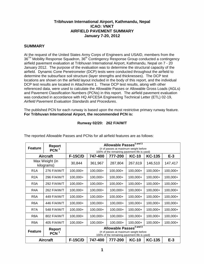
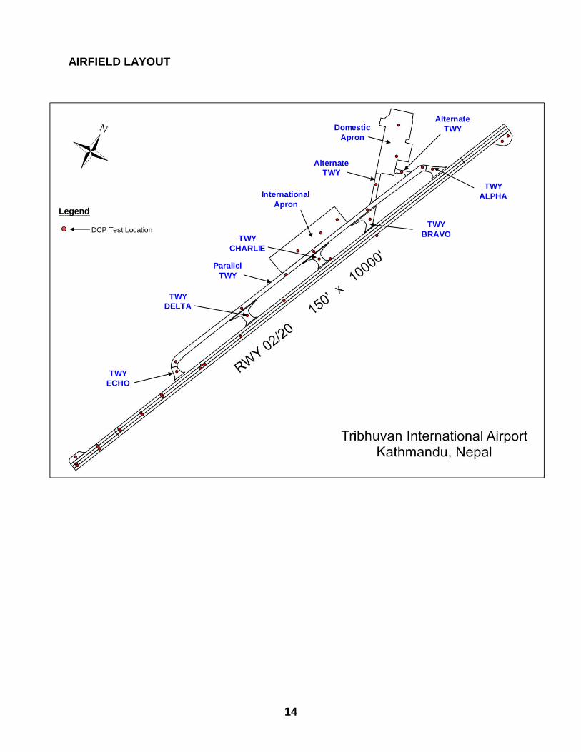
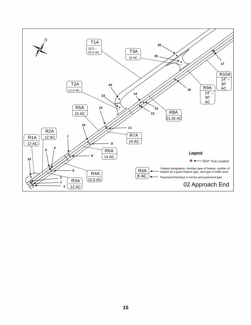
airfield pavement evaluation at Tribhuvan International Airport, Kathmandu, Nepal on 7 - 20 January 2012. The purpose of the evaluation was to determine the structural capacity of the airfield. Dynamic Cone Penetrometer (DCP) tests were conducted throughout the airfield to determine the subsurface soil structure (layer strengths and thicknesses). The DCP test locations are shown on the airfield layout included in the body of this report, and the individual DCP test results are located in Attachment 1. These DCP test results, along with other referenced data, were used to calculate the Allowable Passes or Allowable Gross Loads (AGLs) and Pavement Classification Numbers (PCNs) in this report. The airfield pavement evaluation was conducted in accordance with HQ AFCESA Engineering Technical Letter (ETL) 02-19, Airfield Pavement Evaluation Standards and Procedures. The published PCN for each runway is based upon the most restrictive primary runway feature.
For Tribhuvan International Airport, the recommended PCN is:
Runway 02/20: 262 F/A/W/T The reported Allowable Passes and PCNs for all airfield features are as follows:
Feature Report
PCN 1
Allowable Passes2 and 3
(# of passes at maximum weight before
100% of the remaining pavement life is used)
Aircraft F-15C/D 747-400 777-200 KC-10 KC-135 E-3
Max Weight (in kilograms)
30,844 361,967 287,804 267,619 146,510 147,417
R1A 276 F/A/W/T 100,000+ 100,000+ 100,000+ 100,000+ 100,000+ 100,000+
R2A 296 F/A/W/T 100,000+ 100,000+ 100,000+ 100,000+ 100,000+ 100,000+
R3A 292 F/A/W/T 100,000+ 100,000+ 100,000+ 100,000+ 100,000+ 100,000+
R4A 262 F/A/W/T 100,000+ 100,000+ 100,000+ 100,000+ 100,000+ 100,000+
R5A 449 F/A/W/T 100,000+ 100,000+ 100,000+ 100,000+ 100,000+ 100,000+
R6A 446 F/A/W/T 100,000+ 100,000+ 100,000+ 100,000+ 100,000+ 100,000+
R7A 548 F/A/W/T 100,000+ 100,000+ 100,000+ 100,000+ 100,000+ 100,000+
R8A 802 F/A/W/T 100,000+ 100,000+ 100,000+ 100,000+ 100,000+ 100,000+
R9A 405 F/A/W/T 100,000+ 100,000+ 100,000+ 100,000+ 100,000+ 100,000+
Feature Report
PCN 1
Allowable Passes2 and 3
(# of passes at maximum weight before
100% of the remaining pavement life is used)
Aircraft F-15C/D 747-400 777-200 KC-10 KC-135 E-3
2
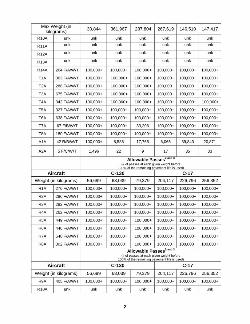
Max Weight (in kilograms)
30,844 361,967 287,804 267,619 146,510 147,417
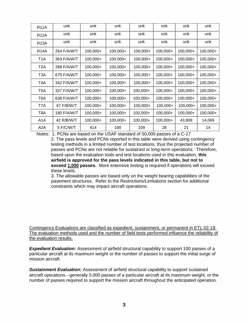
R10A unk unk unk unk unk unk unk
R11A unk unk unk unk unk unk unk
R12A unk unk unk unk unk unk unk
R13A unk unk unk unk unk unk unk
R14A 264 F/A/W/T 100,000+ 100,000+ 100,000+ 100,000+ 100,000+ 100,000+
T1A 363 F/A/W/T 100,000+ 100,000+ 100,000+ 100,000+ 100,000+ 100,000+
T2A 288 F/A/W/T 100,000+ 100,000+ 100,000+ 100,000+ 100,000+ 100,000+
T3A 675 F/A/W/T 100,000+ 100,000+ 100,000+ 100,000+ 100,000+ 100,000+
T4A 342 F/A/W/T 100,000+ 100,000+ 100,000+ 100,000+ 100,000+ 100,000+
T5A 327 F/A/W/T 100,000+ 100,000+ 100,000+ 100,000+ 100,000+ 100,000+
T6A 638 F/A/W/T 100,000+ 100,000+ 100,000+ 100,000+ 100,000+ 100,000+
T7A 67 F/B/W/T 100,000+ 100,000+ 33,206 100,000+ 100,000+ 100,000+
T8A 180 F/A/W/T 100,000+ 100,000+ 100,000+ 100,000+ 100,000+ 100,000+
A1A 42 R/B/W/T 100,000+ 8,586 17,765 6,065 39,843 20,871
A2A 5 F/C/W/T 1,496 22 9 17 35 33
Allowable Passes2 and 3
(# of passes at each given weight before
100% of the remaining pavement life is used)
Aircraft C-130 C-17
Weight (in kilograms) 56,699 68,039 79,379 204,117 226,796 256,352
R1A 276 F/A/W/T 100,000+ 100,000+ 100,000+ 100,000+ 100,000+ 100,000+
R2A 296 F/A/W/T 100,000+ 100,000+ 100,000+ 100,000+ 100,000+ 100,000+
R3A 292 F/A/W/T 100,000+ 100,000+ 100,000+ 100,000+ 100,000+ 100,000+
R4A 262 F/A/W/T 100,000+ 100,000+ 100,000+ 100,000+ 100,000+ 100,000+
R5A 449 F/A/W/T 100,000+ 100,000+ 100,000+ 100,000+ 100,000+ 100,000+
R6A 446 F/A/W/T 100,000+ 100,000+ 100,000+ 100,000+ 100,000+ 100,000+
R7A 548 F/A/W/T 100,000+ 100,000+ 100,000+ 100,000+ 100,000+ 100,000+
R8A 802 F/A/W/T 100,000+ 100,000+ 100,000+ 100,000+ 100,000+ 100,000+
Allowable Passes2 and 3
(# of passes at each given weight before
100% of the remaining pavement life is used)
Aircraft C-130 C-17
Weight (in kilograms) 56,699 68,039 79,379 204,117 226,796 256,352
R9A 405 F/A/W/T 100,000+ 100,000+ 100,000+ 100,000+ 100,000+ 100,000+
R10A unk unk unk unk unk unk unk
3
R11A unk unk unk unk unk unk unk
R12A unk unk unk unk unk unk unk
R13A unk unk unk unk unk unk unk
R14A 264 F/A/W/T 100,000+ 100,000+ 100,000+ 100,000+ 100,000+ 100,000+
T1A 363 F/A/W/T 100,000+ 100,000+ 100,000+ 100,000+ 100,000+ 100,000+
T2A 288 F/A/W/T 100,000+ 100,000+ 100,000+ 100,000+ 100,000+ 100,000+
T3A 675 F/A/W/T 100,000+ 100,000+ 100,000+ 100,000+ 100,000+ 100,000+
T4A 342 F/A/W/T 100,000+ 100,000+ 100,000+ 100,000+ 100,000+ 100,000+
T5A 327 F/A/W/T 100,000+ 100,000+ 100,000+ 100,000+ 100,000+ 100,000+
T6A 638 F/A/W/T 100,000+ 100,000+ 100,000+ 100,000+ 100,000+ 100,000+
T7A 67 F/B/W/T 100,000+ 100,000+ 100,000+ 100,000+ 100,000+ 100,000+
T8A 180 F/A/W/T 100,000+ 100,000+ 100,000+ 100,000+ 100,000+ 100,000+
A1A 42 R/B/W/T 100,000+ 100,000+ 100,000+ 100,000+ 43,908 14,069
A2A 5 F/C/W/T 414 190 109 28 21 14
Notes: 1. PCNs are based on the USAF standard of 50,000 passes of a C-17 2. The pass levels and PCNs reported in this table were derived using contingency testing methods in a limited number of test locations, thus the projected number of passes and PCNs are not reliable for sustained or long-term operations. Therefore,
based upon the evaluation tools and test locations used in this evaluation, this
airfield is approved for the pass levels indicated in this table, but not to
exceed 1,000 passes. More extensive testing is required if operations will exceed these levels. 3. The allowable passes are based only on the weight bearing capabilities of the pavement structures. Refer to the Restrictions/Limitations section for additional constraints which may impact aircraft operations.
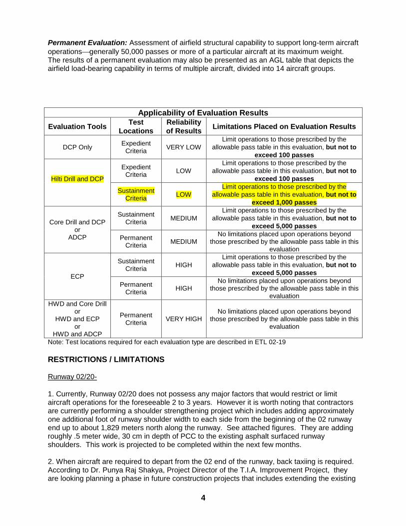
Contingency Evaluations are classified as expedient, sustainment, or permanent in ETL 02-19. The evaluation methods used and the number of field tests performed influence the reliability of the evaluation results.
Expedient Evaluation: Assessment of airfield structural capability to support 100 passes of a particular aircraft at its maximum weight or the number of passes to support the initial surge of mission aircraft.
Sustainment Evaluation: Assessment of airfield structural capability to support sustained
aircraft operationsgenerally 5,000 passes of a particular aircraft at its maximum weight, or the number of passes required to support the mission aircraft throughout the anticipated operation.
4
Permanent Evaluation: Assessment of airfield structural capability to support long-term aircraft
operationsgenerally 50,000 passes or more of a particular aircraft at its maximum weight. The results of a permanent evaluation may also be presented as an AGL table that depicts the airfield load-bearing capability in terms of multiple aircraft, divided into 14 aircraft groups.
Applicability of Evaluation Results
Evaluation Tools Test
Locations
Reliability
of Results Limitations Placed on Evaluation Results
DCP Only Expedient
Criteria VERY LOW
Limit operations to those prescribed by the
allowable pass table in this evaluation, but not to
exceed 100 passes
Hilti Drill and DCP
Expedient Criteria
LOW
Limit operations to those prescribed by the
allowable pass table in this evaluation, but not to
exceed 100 passes
Sustainment Criteria
LOW
Limit operations to those prescribed by the
allowable pass table in this evaluation, but not to
exceed 1,000 passes
Core Drill and DCP or
ADCP
Sustainment Criteria
MEDIUM
Limit operations to those prescribed by the
allowable pass table in this evaluation, but not to
exceed 5,000 passes
Permanent Criteria
MEDIUM No limitations placed upon operations beyond
those prescribed by the allowable pass table in this evaluation
ECP
Sustainment Criteria
HIGH
Limit operations to those prescribed by the
allowable pass table in this evaluation, but not to
exceed 5,000 passes
Permanent Criteria
HIGH No limitations placed upon operations beyond
those prescribed by the allowable pass table in this evaluation
HWD and Core Drill or
HWD and ECP or
HWD and ADCP
Permanent Criteria
VERY HIGH No limitations placed upon operations beyond
those prescribed by the allowable pass table in this evaluation
Note: Test locations required for each evaluation type are described in ETL 02-19
RESTRICTIONS / LIMITATIONS Runway 02/20-
1. Currently, Runway 02/20 does not possess any major factors that would restrict or limit aircraft operations for the foreseeable 2 to 3 years. However it is worth noting that contractors are currently performing a shoulder strengthening project which includes adding approximately one additional foot of runway shoulder width to each side from the beginning of the 02 runway end up to about 1,829 meters north along the runway. See attached figures. They are adding roughly .5 meter wide, 30 cm in depth of PCC to the existing asphalt surfaced runway shoulders. This work is projected to be completed within the next few months. 2. When aircraft are required to depart from the 02 end of the runway, back taxiing is required. According to Dr. Punya Raj Shakya, Project Director of the T.I.A. Improvement Project, they are looking planning a phase in future construction projects that includes extending the existing
5
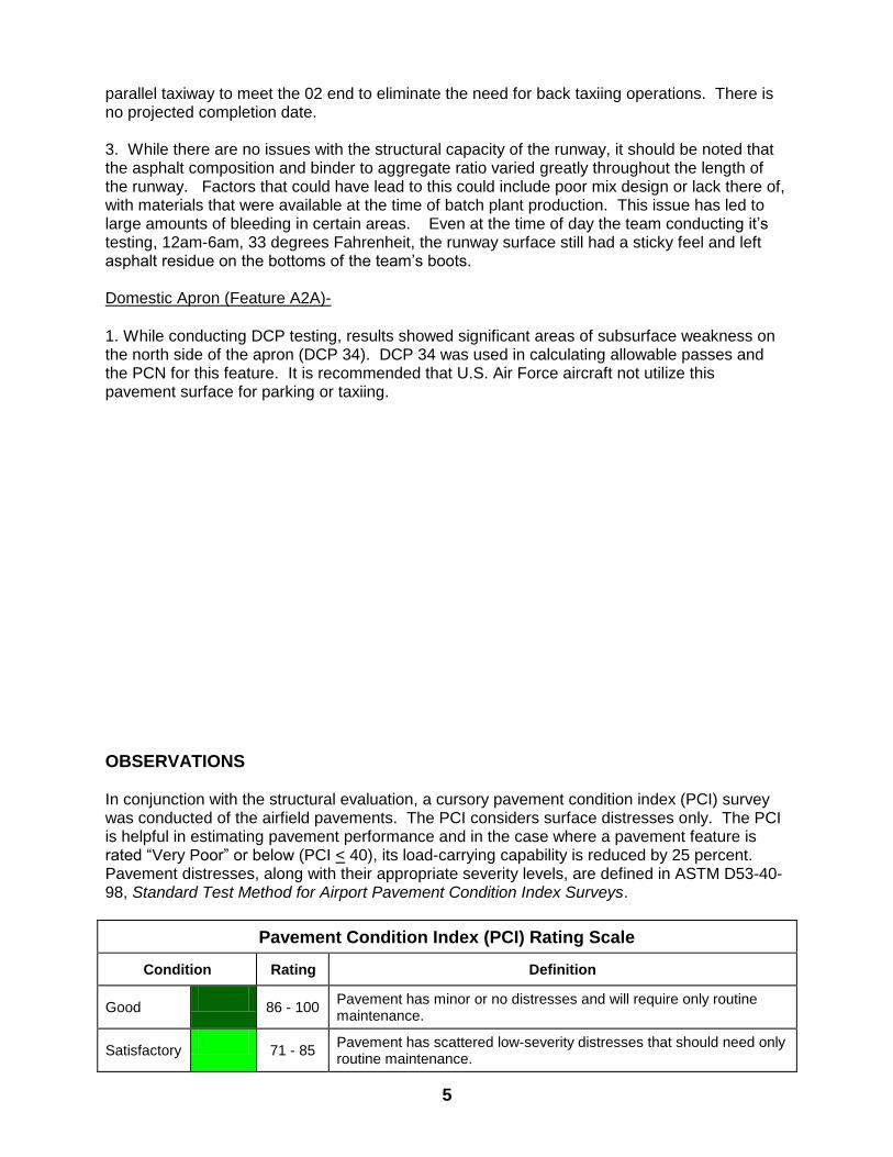
parallel taxiway to meet the 02 end to eliminate the need for back taxiing operations. There is no projected completion date. 3. While there are no issues with the structural capacity of the runway, it should be noted that the asphalt composition and binder to aggregate ratio varied greatly throughout the length of the runway. Factors that could have lead to this could include poor mix design or lack there of, with materials that were available at the time of batch plant production. This issue has led to large amounts of bleeding in certain areas. Even at the time of day the team conducting it’s testing, 12am-6am, 33 degrees Fahrenheit, the runway surface still had a sticky feel and left asphalt residue on the bottoms of the team’s boots. Domestic Apron (Feature A2A)-
1. While conducting DCP testing, results showed significant areas of subsurface weakness on the north side of the apron (DCP 34). DCP 34 was used in calculating allowable passes and the PCN for this feature. It is recommended that U.S. Air Force aircraft not utilize this pavement surface for parking or taxiing.
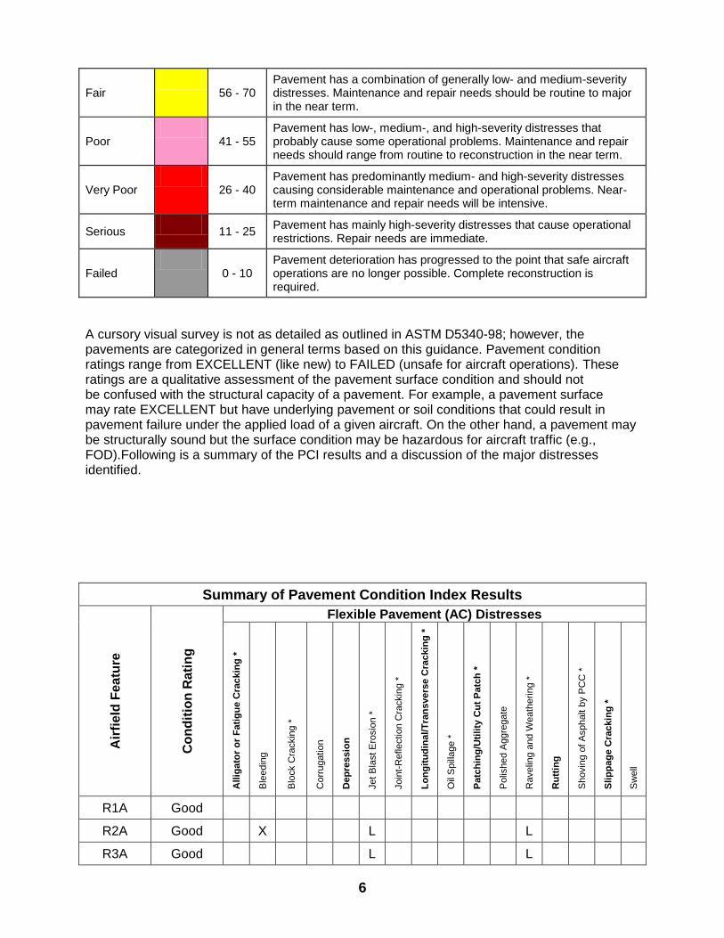
OBSERVATIONS In conjunction with the structural evaluation, a cursory pavement condition index (PCI) survey was conducted of the airfield pavements. The PCI considers surface distresses only. The PCI is helpful in estimating pavement performance and in the case where a pavement feature is rated “Very Poor” or below (PCI < 40), its load-carrying capability is reduced by 25 percent. Pavement distresses, along with their appropriate severity levels, are defined in ASTM D53-40-98, Standard Test Method for Airport Pavement Condition Index Surveys.
Pavement Condition Index (PCI) Rating Scale
Condition Rating Definition
Good
86 - 100 Pavement has minor or no distresses and will require only routine maintenance.
Satisfactory
71 - 85 Pavement has scattered low-severity distresses that should need only routine maintenance.
6
Fair
56 - 70 Pavement has a combination of generally low- and medium-severity distresses. Maintenance and repair needs should be routine to major in the near term.
Poor
41 - 55 Pavement has low-, medium-, and high-severity distresses that probably cause some operational problems. Maintenance and repair needs should range from routine to reconstruction in the near term.
Very Poor
26 - 40 Pavement has predominantly medium- and high-severity distresses causing considerable maintenance and operational problems. Near-term maintenance and repair needs will be intensive.
Serious
11 - 25 Pavement has mainly high-severity distresses that cause operational restrictions. Repair needs are immediate.
Failed
0 - 10 Pavement deterioration has progressed to the point that safe aircraft operations are no longer possible. Complete reconstruction is required.
A cursory visual survey is not as detailed as outlined in ASTM D5340-98; however, the pavements are categorized in general terms based on this guidance. Pavement condition ratings range from EXCELLENT (like new) to FAILED (unsafe for aircraft operations). These ratings are a qualitative assessment of the pavement surface condition and should not be confused with the structural capacity of a pavement. For example, a pavement surface may rate EXCELLENT but have underlying pavement or soil conditions that could result in pavement failure under the applied load of a given aircraft. On the other hand, a pavement may be structurally sound but the surface condition may be hazardous for aircraft traffic (e.g., FOD).Following is a summary of the PCI results and a discussion of the major distresses identified.
Summary of Pavement Condition Index Results
Air
fie
ld F
ea
ture
Co
nd
itio
n R
ati
ng
Flexible Pavement (AC) Distresses
All
iga
tor
or
Fa
tig
ue
Cra
ckin
g *
Ble
edin
g
Blo
ck C
rackin
g *
Corr
ugatio
n
Dep
ressio
n
Jet
Bla
st
Ero
sio
n *
Join
t-R
efle
ctio
n C
rackin
g *
Lo
ng
itu
din
al/
Tra
ns
vers
e C
rackin
g *
Oil
Spill
age *
Patc
hin
g/U
tili
ty C
ut
Patc
h *
Polis
hed A
ggre
gate
Ravelin
g a
nd W
eath
erin
g *
Ru
ttin
g
Shovin
g o
f A
sphalt b
y P
CC
*
Sli
pp
ag
e C
rackin
g *
Sw
ell
R1A Good
R2A Good X L L
R3A Good L L
7
R4A Good X L L
R5A Sat X L L
R6A Sat X L L
R7A Sat X L L
R8A Good L L
R9A Good X L
R10A Good X
R11A Good
R12A Good X
R13A Good
R14A Good
T1A Good X L
T2A Good
T3A Good X L
T4A Good
T5A Good X
T6A Good X L
T7A Good
T8A Good
A2A Sat X L X L
Air
fie
ld F
ea
ture
Co
nd
itio
n R
ati
ng
Rigid Pavement (PCC) Distresses
Blo
wup *
Co
rne
r B
reak
*
Lo
ng
itu
din
al,
Tra
ns
vers
e C
rackin
g *
Dura
bili
ty “
D”
Cra
ckin
g *
Join
t S
eal D
am
age
*
Patc
h,
Sm
all
(< 5
sf)
*
Patc
h,
La
rge
/Uti
lity
Cu
t (>
5 s
f) *
Popouts
*
Pu
mp
ing
*
Scalin
g /
Ma
p C
rackin
g *
Sett
lem
en
t /
Fa
ult
ing
Sh
att
ere
d S
lab
/ I
nte
rsecti
ng
Cra
cks
*
Shrin
kage C
rackin
g
Spalli
ng,
Join
ts *
Spalli
ng,
Corn
er
*
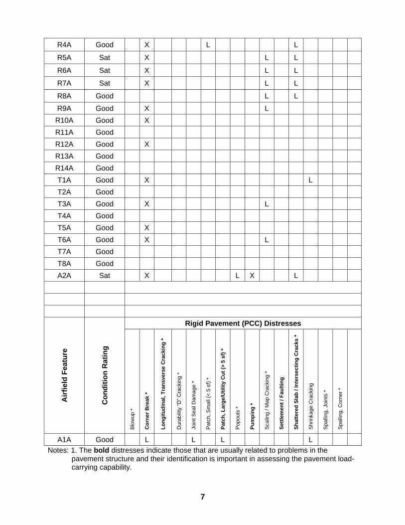
A1A Good L L L L
Notes: 1. The bold distresses indicate those that are usually related to problems in the pavement structure and their identification is important in assessing the pavement load-carrying capability.
8
2. The distresses followed by an asterisk are those that may produce FOD. Although they all may not significantly impact the computed allowable passes, they may limit the operational capability of the pavement. 3. Distress Severity Levels: X= Distress Exists, L = Low, M = Medium, H = High
RUNWAY 02/20-
While conducting visual inspections and DCP operations, a few existing distresses and concerns were observed. The overall condition of the runway appeared to be in good condition with some minor pavement distresses. During the vehicular visual inspection of the runway, it was somewhat noticeable where specific paving lanes and construction phase start/stop points existed due to the rather easy ability to feel these locations along the asphalt. This may be due to regularly practiced construction methods within the country of Nepal and its contractors. It was also confirmed that it is not regular practice for Nepalese contractors to perform a saw cut at the end of paving lanes. Regular procedures included placing and rolling asphalt fill material over construction joints. Low severity small and large patching/utility cuts were observed throughout the runway. During discussions with the contractor, it was admitted that full depth repairs were not usually conducted because of the inability to obtain large quantities of repair materials and due to the excessive thickness of the existing runway’s asphalt pavement. Rubber removal has yet to be accomplished on runway 02/20 which equates to approximately three years of buildup. This buildup will lead to aircraft traction loss during take-off and landing. It is recommended that rubber removal be accomplished within the next 12 months. PARALLEL TWY- (Feature T1A)
Some low severity rutting was observed near the south end of the international apron with ruts between 6.4mm to 12.7mm. These areas should be continuously observed to detect any changes in rutting depth. Low severity bleeding also exists in a few areas on the parallel near the international apron and specifically near those areas where the rutting was observed. INTERNATIONAL APRON- (Feature A1A) Low severity joint sealant damage was observed in a few locations with most joint sealant in good condition throughout the apron. Accumulation of incompressible materials prevents the slabs from expanding and may result in buckling, shattering, or spalling. A pliable joint filler bonded to the edges of the slabs protects the joints from accumulation of materials and also prevents water from seeping down and softening the foundation supporting the slab. (UFC 3-270-05) We recommend monitoring joint sealant to maintain its current quality. DOMESTIC APRON- (Feature A2A) 70% of the apron contained spots where fuel/oil spills had occurred. Nearly every parking spot on the apron had one or more spills that varied in size. Over time, these spills could have an effect on the integrity of the asphalt with which it contacts.
9
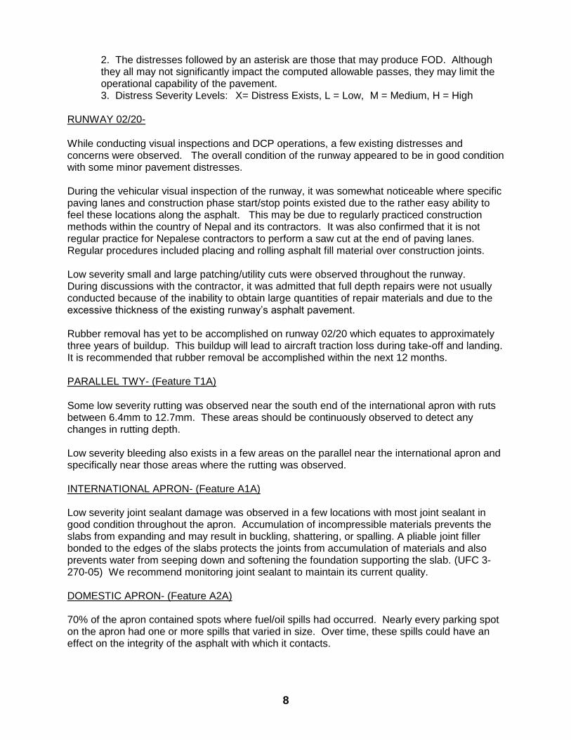
A few potholes were present in the apron with diameters from 50-150 mm and depths from 25 to 50 mm, and may represent a delamination problem along some of the paving lane joints. These potholes should be repaired with partial-depth asphalt patches. Low severity longitudinal cracking was present within the area of DCP # 35. Longitudinal cracks are parallel to the pavement’s center-line or lay down direction. They may be caused by a poorly constructed paving lane joint or shrinkage of the AC surface due to low temperatures or hardening of the asphalt.
Photographs
Fig 1, Longitudinal Cracking, Domestic Apron Fig 2, Joint Sealant Damage, International Apron
Fig 3,Corner Break, International Apron Fig 4, Shrinkage Cracking, International Apron
10
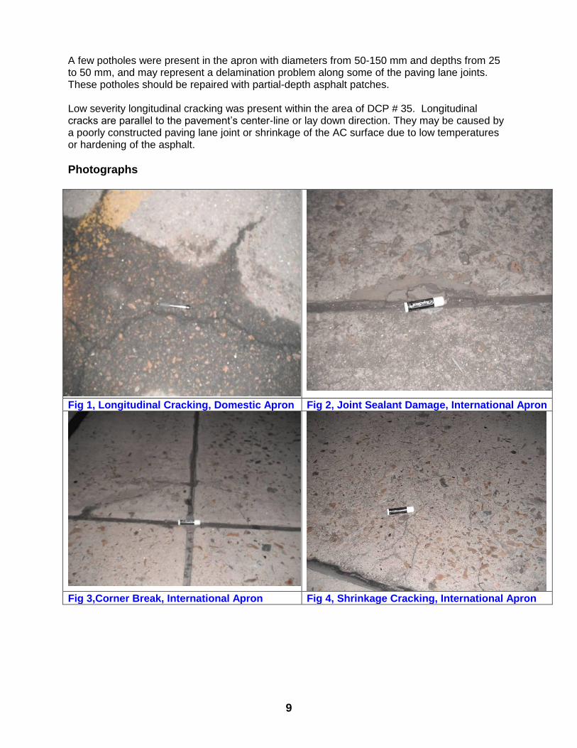
Fig 5, Bleeding, Present on most features Fig 6, Shoulder Repairs currently being
conducted along Runway 02/20
Fig 7, Shoulder Repairs currently being
conducted along Runway 02/20
Fig 8, Vegetation around Runway lights
11
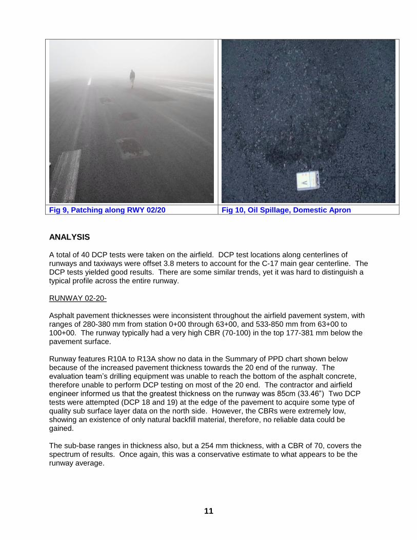
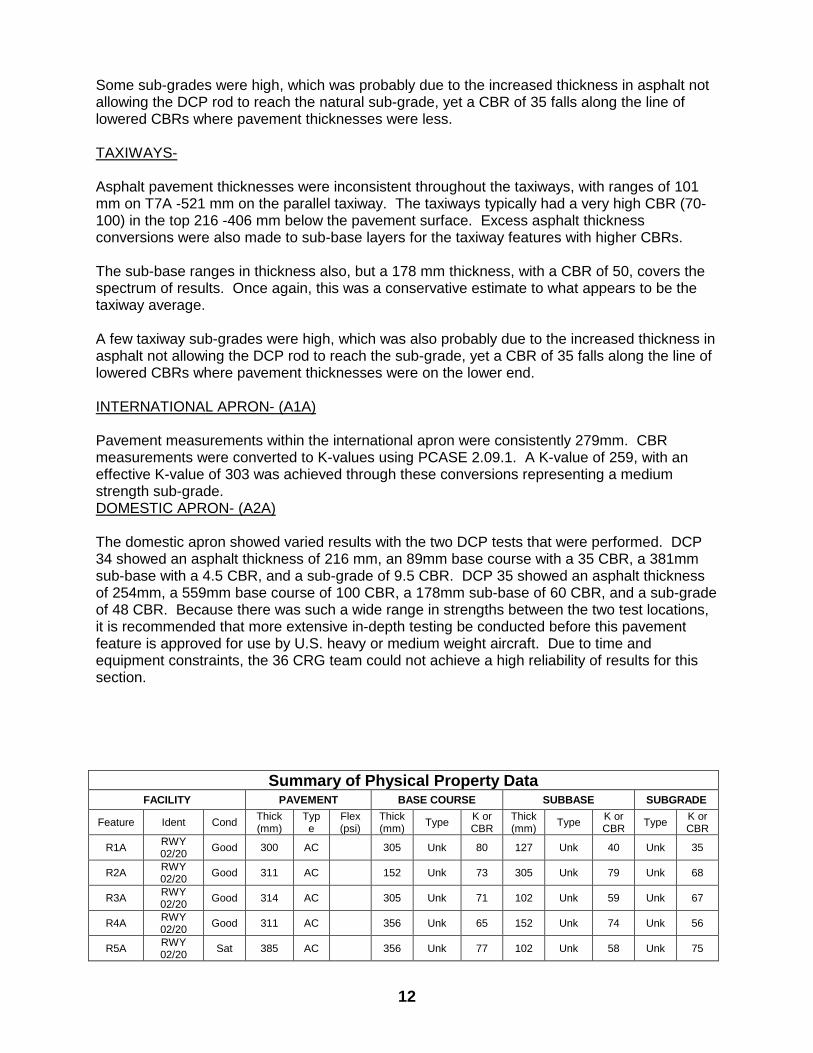
Fig 9, Patching along RWY 02/20 Fig 10, Oil Spillage, Domestic Apron
ANALYSIS
A total of 40 DCP tests were taken on the airfield. DCP test locations along centerlines of runways and taxiways were offset 3.8 meters to account for the C-17 main gear centerline. The DCP tests yielded good results. There are some similar trends, yet it was hard to distinguish a typical profile across the entire runway. RUNWAY 02-20- Asphalt pavement thicknesses were inconsistent throughout the airfield pavement system, with ranges of 280-380 mm from station 0+00 through 63+00, and 533-850 mm from 63+00 to 100+00. The runway typically had a very high CBR (70-100) in the top 177-381 mm below the pavement surface. Runway features R10A to R13A show no data in the Summary of PPD chart shown below because of the increased pavement thickness towards the 20 end of the runway. The evaluation team’s drilling equipment was unable to reach the bottom of the asphalt concrete, therefore unable to perform DCP testing on most of the 20 end. The contractor and airfield engineer informed us that the greatest thickness on the runway was 85cm (33.46”) Two DCP tests were attempted (DCP 18 and 19) at the edge of the pavement to acquire some type of quality sub surface layer data on the north side. However, the CBRs were extremely low, showing an existence of only natural backfill material, therefore, no reliable data could be gained. The sub-base ranges in thickness also, but a 254 mm thickness, with a CBR of 70, covers the spectrum of results. Once again, this was a conservative estimate to what appears to be the runway average.
12
Some sub-grades were high, which was probably due to the increased thickness in asphalt not allowing the DCP rod to reach the natural sub-grade, yet a CBR of 35 falls along the line of lowered CBRs where pavement thicknesses were less. TAXIWAYS- Asphalt pavement thicknesses were inconsistent throughout the taxiways, with ranges of 101 mm on T7A -521 mm on the parallel taxiway. The taxiways typically had a very high CBR (70-100) in the top 216 -406 mm below the pavement surface. Excess asphalt thickness conversions were also made to sub-base layers for the taxiway features with higher CBRs. The sub-base ranges in thickness also, but a 178 mm thickness, with a CBR of 50, covers the spectrum of results. Once again, this was a conservative estimate to what appears to be the taxiway average. A few taxiway sub-grades were high, which was also probably due to the increased thickness in asphalt not allowing the DCP rod to reach the sub-grade, yet a CBR of 35 falls along the line of lowered CBRs where pavement thicknesses were on the lower end. INTERNATIONAL APRON- (A1A) Pavement measurements within the international apron were consistently 279mm. CBR measurements were converted to K-values using PCASE 2.09.1. A K-value of 259, with an effective K-value of 303 was achieved through these conversions representing a medium strength sub-grade. DOMESTIC APRON- (A2A) The domestic apron showed varied results with the two DCP tests that were performed. DCP 34 showed an asphalt thickness of 216 mm, an 89mm base course with a 35 CBR, a 381mm sub-base with a 4.5 CBR, and a sub-grade of 9.5 CBR. DCP 35 showed an asphalt thickness of 254mm, a 559mm base course of 100 CBR, a 178mm sub-base of 60 CBR, and a sub-grade of 48 CBR. Because there was such a wide range in strengths between the two test locations, it is recommended that more extensive in-depth testing be conducted before this pavement feature is approved for use by U.S. heavy or medium weight aircraft. Due to time and equipment constraints, the 36 CRG team could not achieve a high reliability of results for this section.
Summary of Physical Property Data FACILITY PAVEMENT BASE COURSE SUBBASE SUBGRADE
Feature Ident Cond Thick (mm)
Type
Flex (psi)
Thick (mm)
Type K or CBR
Thick (mm)
Type K or CBR
Type K or CBR
R1A RWY 02/20
Good 300 AC 305 Unk 80 127 Unk 40 Unk 35
R2A RWY 02/20
Good 311 AC 152 Unk 73 305 Unk 79 Unk 68
R3A RWY 02/20
Good 314 AC 305 Unk 71 102 Unk 59 Unk 67
R4A RWY 02/20
Good 311 AC 356 Unk 65 152 Unk 74 Unk 56
R5A RWY 02/20
Sat 385 AC 356 Unk 77 102 Unk 58 Unk 75
13
R6A RWY 02/20
Sat 375 AC 406 Unk 80 267 Unk 95 Unk 60
R7A RWY 02/20
Sat 355 AC 203 Unk 100 254 Unk 80 Unk 65
FACILITY PAVEMENT BASE COURSE SUBBASE SUBGRADE
Feature Ident Cond Thick (mm)
Type Flex (psi)
Thick (mm)
Type K or CBR
Thick (mm)
Type K or CBR
Type K or CBR
R8A RWY 02/20
Good 540 AC 178 Unk 80 178 Unk 100 Unk 80
R9A RWY 02/20
Good 550 AC 178 Unk 100 229 Unk 50 Unk 25
R10A RWY 02/20
Good 550 AC Unk Unk Unk Unk Unk Unk Unk Unk
R11A RWY 02/20
Good Unk AC Unk Unk Unk Unk Unk Unk Unk Unk
R12A RWY 02/20
Good Unk AC Unk Unk Unk Unk Unk Unk Unk Unk
R13A RWY 02/20
Good Unk AC Unk Unk Unk Unk Unk Unk Unk Unk
R14A RWY 02/20
Good 330 AC 279 Unk 100 102 Unk 70 Unk 25
T1A PARA TWY
Good 387 AC 305 Unk 62 152 Unk 77 Unk 87
T2A TWY
ECHO Good 290 AC 305 Unk 84 305 Unk 41 Unk 55
T3A TWY
DELTA Good 406 AC 254 Unk 100 279 Unk 100 Unk 90
T4A TWY
CHARLIE Good 356 AC 254 Unk 85 127 Unk 55 Unk 35
T5A TWY
BRAVO Good 356 AC 229 Unk 67 152 Unk 45 Unk 35
T6A TWY
ALPHA Good 391 AC 216 Unk 100 178 Unk 80 Unk 70
T7A Alt TWY Good 119 AC 533 Unk 90 191 Unk 30 Unk 8
T8A Alt TWY Good 279 AC 203 Unk 55 330 Unk 37 Unk 22
A1A Internat. Apron
Good 279 PCC 600 152 Unk 345 212 Unk 259 Unk 286
A2A Domestic
Apron Sat 235 AC 89 Unk 35 381 Unk 4.5 Unk 9.5
Notes: 1. For flexible pavement (AC) features and semi-prepared features, the soil layer thicknesses and CBRs shown were determined from DCP tests. 2. For rigid pavement (PCC) features, the PCC flexural strengths shown were assumed based upon the location of the airfield. 3. For rigid pavement (PCC) features, the soil layer K-values shown were determined from DCP vs. CBR, and CBR vs. K-value correlations. The measured K-value for each layer is shown, along with the layer thickness. The measured K-value that results in the lowest effective K-value for
each feature is shown in bold type. In turn, the lowest effective K-value is used to evaluate the pavement feature. (Ref. ETL 02-19)
Allowable passes based upon the feature data in the Summary of Physical Property Data table and
DCP test results were determined using PCASE software version 2.09.1.
14
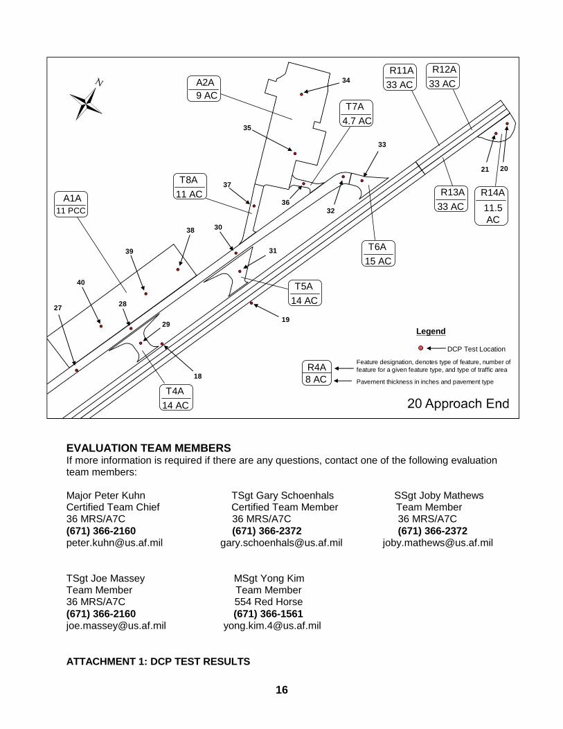
AIRFIELD LAYOUT
Legend
DCP Test Location
Domestic
Apron
International
Apron
TWY
ECHO
TWY
DELTA
Parallel
TWY
TWY
BRAVOTWY
CHARLIE
Alternate
TWY
Alternate
TWY
TWY
ALPHA
15
22
3
1
2
5
6
4
7
8
9
1011
12
23
24
13
15
14
16
17
26
25
Legend
DCP Test Location
R4A
8 AC
Feature designation, denotes type of feature, number of
feature for a given feature type, and type of traffic area
Pavement thickness in inches and pavement type
Test 4
R4A
12.5 AC
T1A
10.5 –
20.5 AC
T2A
11.5 AC
T3A
16 AC
R1A
12 AC
R2A
12 AC
R3A
12 AC
R9C14” –
30”AC R5A
15 AC
R6A
14 AC
R7A
14 AC
R8A
21.25 AC
R9A14” –30”
AC
R10A14” –
30”AC
16
21 20
33
32
36
19
18
29
31
34
35
37
3038
39
40
2728
Legend
DCP Test Location
R4A
8 AC
Feature designation, denotes type of feature, number of
feature for a given feature type, and type of traffic area
Pavement thickness in inches and pavement type
Test 4
T8A
11 AC
A2A
9 AC
A1A
11 PCC
R11A
33 AC
R12A
33 AC
R13A
33 AC
R14A
11.5
AC
T4A
14 AC
T5A
14 AC
T6A
15 AC
T7A
4.7 AC
EVALUATION TEAM MEMBERS If more information is required if there are any questions, contact one of the following evaluation team members: Major Peter Kuhn TSgt Gary Schoenhals SSgt Joby Mathews Certified Team Chief Certified Team Member Team Member 36 MRS/A7C 36 MRS/A7C 36 MRS/A7C
(671) 366-2160 (671) 366-2372 (671) 366-2372 [email protected] [email protected] [email protected]
TSgt Joe Massey MSgt Yong Kim Team Member Team Member 36 MRS/A7C 554 Red Horse
(671) 366-2160 (671) 366-1561 [email protected] [email protected]
ATTACHMENT 1: DCP TEST RESULTS
TRIBHUVAN INTERNATIONAL AIRPORT PAVEMENT ANALYSIS
FINAL REPORT
17
RECOMMENDATIONS
As a result of the visual inspection of the Tribhuvan International Airport’s (TIA) airfield and a review of
the preceding report, there are additional projects that should be implemented to improve the existing
conditions of the runway system and increase its capacity to withstand a seismic event.
Several of the distresses pointed out by the Pavement Condition Index (PCI) are related to airfield
surface drainage. The vegetation at the TIA airfield currently grows to the edge of the pavement
structures. This vegetation has a deep root system that transports moisture to the base and sub-base of
the pavement structures. As a result, it undermines the structural capacity and compaction of these
layers below the asphalt surface.
In some areas between the runway and the taxiways, the height of the vegetation and swelling of the
soil are causing visible damage to the airfield surfaces. To remedy this situation, the areas need to be
leveled below the pavement surfaces. This will reduce runoff that is currently collecting at the runway
and taxiways, which is causing airfield surface distresses.
A project to grade the areas and establish gentle and clean slopes to the existing ditch and drainage
system of the airfield will reduce the water infiltration. There should be a margin of not less than two
meters between the vegetation and the edge of the pavement structures. This will remove the channels
provided by the roots that are currently moving water between the layers and below the surface causing
damage. These shoulders should be treated with environmentally-friendly vegetation prevention
products, and provided with a thin bituminous layer to prevent further growth.
The project to provide proper drainage slopes for the runway system should include a removal of the
vegetation to a minimum of two meters from any pavement edge. This work should be accomplished
using a grader and applying herbicide. A deeper concrete edge should be installed along the edge of the
airfield surfaces to prevent further growth and sub-surface water infiltration. The concrete edge that is
currently being installed along the TIA runway will only have marginal results due to the depth of this
structure. In most cases, it reaches only 12 inches. However, the vegetation root system is much
deeper, carrying moisture to the base and sub-base of the runway and proliferating long-term runway
maintenance and operational concerns. In regards to the taxiway, it is currently not fitted with a
concrete edge at all. Therefore, vegetation should be cut and removed away from the paved structures
until a concrete edge can be installed.
The existing soil swelling of the grass infields requires reshaping. A grader should be used to allow for a
more efficient flow of the runoff. This will reduce ponding and water retention in the operational areas.
By reducing the time available for water to pond near the runway system, the possibility of water
infiltration will be reduced considerably. As a result, the damage to the sub-structures will be
minimized.
TRIBHUVAN INTERNATIONAL AIRPORT PAVEMENT ANALYSIS
FINAL REPORT
18
Excess infield material should be removed using a wheeled front-end loader and dump trucks. Use of
track equipment should not be allowed. Track equipment will cause further damage to the paved
structures and exacerbate the problem.
Prior to completing the grading project, all cables servicing the navigational aids and equipment facilities
located in the airfield need to be identified and drafted for future reference. Unfortunately, the Civil
Aviation Authority of Nepal (CAAN) does not currently have a complete set of construction documents
showing the location of such cables and duct banks. It is necessary to complete this task prior to
completing the aforementioned grading projects. In some cases, it may be necessary to re-install the
cables at proper depths, which could allow periodic grading and maintenance of the drainage surfaces t
be completed at the same time.
The cable location project needs to be completed using specific cable locator equipment. The
equipment needs to allow for the proper location of all field cables to a depth of 60 inches or more.
Existing drawings, hand-digging, or other methods should be used to determine accurate cable
locations. Drawings need to be updated or created to accurately depict the location, direction, and
depth of all cables. With this information, a grading plan can be generated and the appropriate depth of
cut and fill can be calculated. This will produce gentle slopes required to connect the edges of the paved
surfaces of the runway system with the existing brick-lined ditch system.
If the existing depth of the cables are too shallow or the grade angle is too steep to prevent systematic
mowing of the infield areas, then these cables should be re-installed to adequate depths using a ditch
witch; digging parallel trenches with back hoes; or by hand-digging. Cable splicing should be minimized,
and if unavoidable, proper splicing kits should be installed to preserve the integrity of the cables and
their insulation. In some cases, new cables could be required due to the age or the complexity of the
installation. The personnel completing this task should prepare a cable re-installation plan in
conjunction with CAAN to ensure the availability of materials required to complete the project. The plan
should be generated prior to attempting any cable re-installation.
The two main projects described in this recommendation section should be completed during hours of
minimal air traffic. These hours are typically from 2400 until 0500 or 600. To ensure worker safety, it is
vital that CAAN or others secure portable construction lighting equipment (powered by engine
generators) that are reliable and do not cause damage to paved surfaces (leaking fuels damage the
pavement creating weak surfaces that require additional treatment).
It is common to experience a work delay caused by the need for airfield operations to continue. For that
reason, it is imperative that close coordination occurs with CAAN, TIA, the Nepal Army, and others.
CAAN can provide appropriate time slots that will be adequate for working in certain areas of the airfield
without disturbing the operations of the airport.
After these projects are underway, CAAN needs to provide periodic upgrades and revisions of its “as
built” drawings for every modification completed in the airfield. CAAN should also take the
TRIBHUVAN INTERNATIONAL AIRPORT PAVEMENT ANALYSIS
FINAL REPORT
19
responsibility of maintaining proper drainage of the airfield to reduce damage to the paved surfaces
caused from water infiltration to the sub-structures.
It is of utmost important to emphasize the need for periodic maintenance of all airfield surfaces.
Allowing vegetation to grow unattended increases water-carrying capacity of the root system. This
leads to a higher probability of damaging the base and sub-base of the runway and taxiway system.
Mowing should be completed monthly to maintain proper drainage of the infields. The recommended
two meter margin around the edge of all paved surfaces needs to be treated continuously with
vegetation prevention agents. This will allow water to quickly move to the ditch system in the infields.
The ditch system needs to be maintained periodically to avoid vegetation growth and reduce cracking of
joints. The passage of water under taxiways, runways, aprons, roads, etc. need to be cleared of debris
and vegetation. This will ensure sufficient space for planned runoff (100-year storm) to flow without
creating backup that will undermine the intake structures of existing culverts and tunnels.
The light system currently installed in the runway shoulder is receding due to multiple pavement
overlays. This situation should be corrected to comply with international aviation regulations for safe
operations. The lights need to be raised using approved manufactured frangible methods. Additionally,
the surrounding areas require installation of leveling grout or asphalt products to reduce the severity of
the existing slopes and eliminate “potholes,” which also contribute to water-ponding near the runway
and taxiways.
It is recommended that the Civil Aviation Authority of Nepal utilize cement for the upcoming runway
lengthening project. This will maximize the runway lifecycle against constant landings and 180 degree
turnarounds forced by the current lack of a parallel taxiway to the hammerhead.
Finally, all airfield distress notations in this report should be acted upon. If neglected, these minor
issues could escalate to severe problems. Bleeding, longitudinal cracking, joint seal damage, patching,
and oil spillage should be remedied as soon as possible. If the appropriate equipment and/or supplies
are not available to make these repairs, then the equipment and supplies should be purchased and
warehoused so that these distresses can be reduced and safe operations can continuously occur.
Following the recommendations in this report will promote safety, operational efficiency, and a
commitment of excellence to follow all international regulations. Not following through with the
periodic maintenance of the airfield pavement system and its related infields will result in a substantial
reduction of allowable PCN and air operations.
TRIBHUVAN INTERNATIONAL AIRPORT PAVEMENT ANALYSIS
FINAL REPORT
20
REFERENCE DOCUMENTS
The following civilian airfield references have been compiled to guide future repairs at the Tribhuvan
International Airport (VNKT) in Kathmandu, Nepal.
International Civil Aviation Organization (ICAO) Regulations
--------------------------------------------------------------------------------------------------- ICAO ANNEX 14 Volume I - Aerodrome Design and Operations, July 2009 2.6.2. The bearing strength of a pavement intended for aircraft of apron (ramp) mass greater than 5700 kg shall be made available using the aircraft classification number — pavement classification number (ACN-PCN) method by reporting all of the following information: 10.3 [Pavement Overlays] (2.6.2 identifies that ACN-PCN is the accepted methodology for determining pavement strength at ICAO airports, and is also the same weight bearing results that the CRG pavement team provided in their report.)
--------------------------------------------------------------------------------------------------- ACI Policy and Recommended Practices Handbook | Seventh Edition | November 2009 Airport Planning, Design, Operation and Safety 5.4.1c Runway shoulders should be provided to minimize damage to aircraft running off the runway, to prevent ingestion of loose soil particles, to avoid erosion of the soil by jet engine blast, and to allow easy access by rescue and fire-fighting vehicles. The type and width of these shoulders, if any, should be determined by the characteristics of the most demanding aircraft serving the airport, the type of soil, local drainage and vegetation, and the requirements of rescue and fire-fighting vehicles. The total width of runway pavement including shoulders should not be required to exceed 60 meters for Code E, or 75 meters for Code F.
---------------------------------------------------------------------------------------------------- Doc 9157, Aerodrome Design Manual, Part 1 - Runways Doc 9157, Aerodrome Design Manual, Part 2 - Taxiways, Aprons and holding bays Doc 9157, Aerodrome Design Manual, Part 3 — Pavements, Chapter 5 Doc 9157, Aerodrome Design Manual, Part 4 - Visual Aids Doc 9157, Aerodrome Design Manual, Part 5 - Electrical Systems Doc 9157P6, Aerodrome Design Manual, Part 6F - Frangibility
Federal Standards (Advisory Circulars)
Advisory Circulars AC 150/5320-5, Surface Drainage Design
TRIBHUVAN INTERNATIONAL AIRPORT PAVEMENT ANALYSIS
FINAL REPORT
21
AC 150/5320-6, Airport Pavement Design and Evaluation
AC 150/5370-10, Standards for Specifying Construction of Airports Airport Construction Standards
AC 150/5320-5C, Surface Drainage Design, is a joint FAA/DOD regulation assigned as UFC 3-230-01. Chapter 7 identifies special design concerns for airfields, but the same criteria are utilized for drainage by both the FAA and DOD.
AC 150/5320-6, Airport Pavement Design and Evaluation, is a FAA-only regulation. Additional ACs that would be useful for reference/information:
1. AC 150/5300-9, Pre-Design, Pre-Bid, and Pre-Construction Conferences for Airport Grant Projects. 2. AC 150/5300-13, Airport Design. 3. AC 150/5320-5, Surface Drainage Design. 4. AC 150/5320-12, Measurement, Construction and Maintenance of Skid Resistance Airport Pavement Surfaces. 5. AC 150/5320-17, Airfield Pavement Surface Evaluation and Rating Manual. 6. AC 150/5335-5, Standardized Method of Reporting Airport Pavement Strength-PCN. 7. AC 150/5340-30, Design and Installation Details for Airport Visual Aids. 8. AC 150/5370-10, Standard for Specifying Construction of Airports. 9. AC 150/5370-11, Use of Nondestructive Testing Devices in the Evaluation of Airport Pavement. 10. AC 150/5370-14, Hot Mix Asphalt Paving Handbook. 11. AC 150/5380-6, Guidelines and Procedures for Maintenance of Airport Pavements. 12. Order 5300.7, Standard Naming Convention for Aircraft Landing Gear Configurations The advisory circulars and orders are available for download on the FAA website at http://www.faa.gov.


