
Tray Column Design
17
Tray Column Design : Keep Control of the Details Intelligent effective Specifying of the trays for a distillation or stripping column involves much more than simply choosing the right kind of tray By: Brian Lee (13007006) Laras Wuri Dianningrum (13007075)
-
Upload
laras-wuri-d -
Category
Documents
-
view
3.351 -
download
17
description
Resume of Siddhartha Mukherjee, Lurgi India Co. Ltd. paper "Tray Column Design, Keep Control of the Details"
Transcript of Tray Column Design
Tray Column Design :Keep Control of the
DetailsIntelligent effective
Specifying of the trays for a distillation or stripping column involves much
more than simply choosing the right kind of tray
By:Brian Lee (13007006)Laras Wuri Dianningrum (13007075)
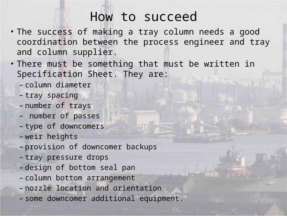
How to succeed• The success of making a tray column needs a good coordination
between the process engineer and tray and column supplier. • There must be something that must be written in Specification
Sheet. They are:– column diameter – tray spacing– number of trays– number of passes– type of downcomers– weir heights– provision of downcomer backups– tray pressure drops– design of bottom seal pan– column bottom arrangement– nozzle location and orientation– some downcomer additional equipment.
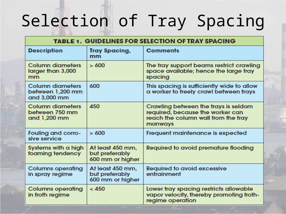
Selection of Tray Spacing
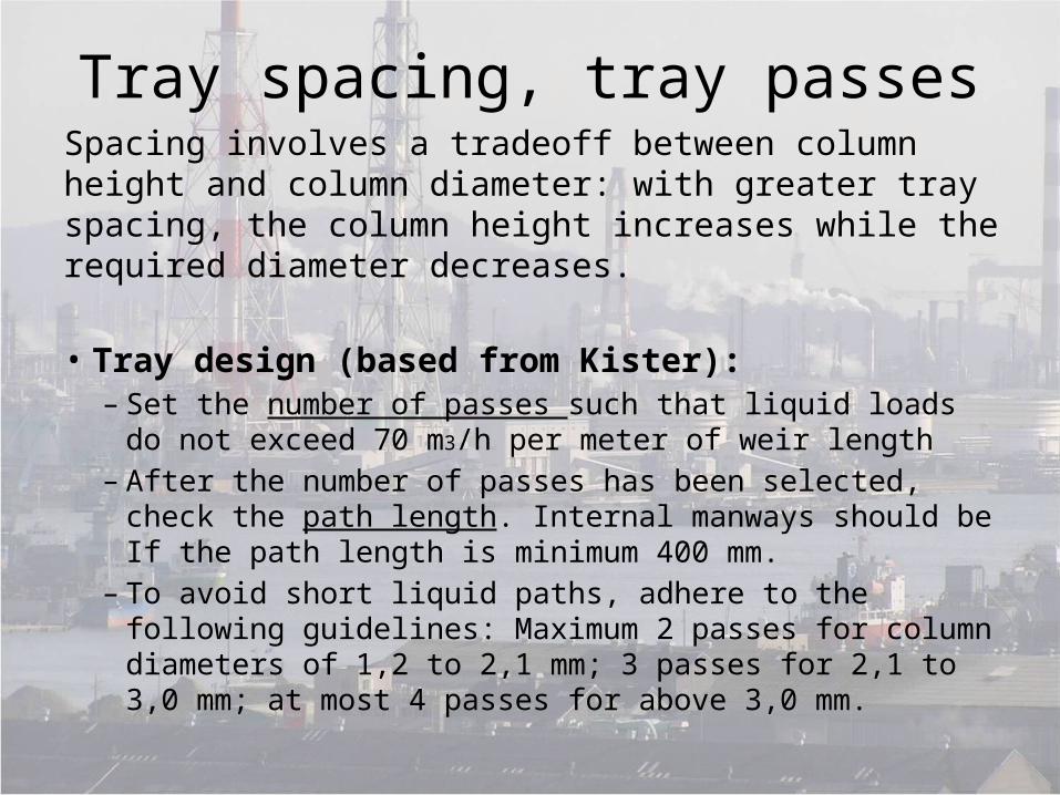
Tray spacing, tray passesSpacing involves a tradeoff between column height and column diameter: with greater tray spacing, the column height increases while the required diameter decreases.
• Tray design (based from Kister):– Set the number of passes such that liquid loads do not
exceed 70 m3/h per meter of weir length – After the number of passes has been selected, check the
path length. Internal manways should be If the path length is minimum 400 mm.
– To avoid short liquid paths, adhere to the following guidelines: Maximum 2 passes for column diameters of 1,2 to 2,1 mm; 3 passes for 2,1 to 3,0 mm; at most 4 passes for above 3,0 mm.
Downcomer Types
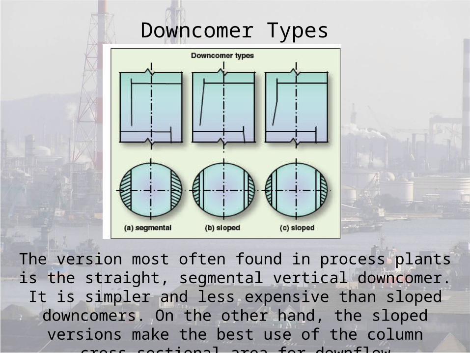
The version most often found in process plants is the straight, segmental vertical downcomer. It is simpler and less expensive than sloped downcomers. On the other hand, the sloped versions make
the best use of the column cross-sectional area for downflow

Liquid Velocities in Downcomer
• The maximum velocity of clear liquid in the downcomer is governed by the need to prevent choking, and to achieve satisfactory separation of the vapor bubbles from the downcomer liquid.
• Recommended downcomer velocities are:– Minimally foaming liquids: 0.12–0.21 m/s– Liquids with medium foaming tendency: 0.09–0.18
m/s– Highly foaming liquids: 0.06–0.09 m/s
Downcomers Areas• Smaller downcomers adversely affect the pattern of
the liquid flow as it approaches the weir, increasing the pressure drop and promoting the formation of stagnant regions near the edges of the tray.
• Another rule of thumb for single pass trays is to have the downcomer width not less than 10% of the column diameter.
• Be sure to specify the downcomer clearance so as to be less than the outlet weir height; otherwise, vapor will flow up the downcomer rather than through the tray deck above.
Downcomer Sealing
• To achieve a proper downcomer seal, the bottom edge of the downcomer shouldbe about 10 mm below the top edge of the outlet weir.
• According to another guideline, the downcomer clearance should be selected such that the liquid velocity under the downcomer does not exceed 0.45 – 0.50 m/s.
• The best downcomer clearance can only be specified by the tray vendor.
Weir• The purpose of an outlet weir is to keep the liquid level
on the tray at the intended value.
• Outlet weirs should be included in the specification, for two reasons: an onset of froth-regime operation may arise if the vapor rate falls off for some reason, and the presence of the weir will limit spray-regime entrainment. The preferred weir height for columns operating in the spray regime is 20–25 mm.
• Weir loadings should fall within the range of 15 to 70 m3/h per meter of weir length.

Pressure Drops
• The pressure drop across the tray is the sum of two components
• One is the dry-tray pressure drop, namely, the loss in pressure of the vapor as it flows upward through the tray holes.
• The second component, the hydraulic-tray pressure drop, arises because of the head of liquid on the tray, which the rising vapor has to overcome to reach the liquid surface.
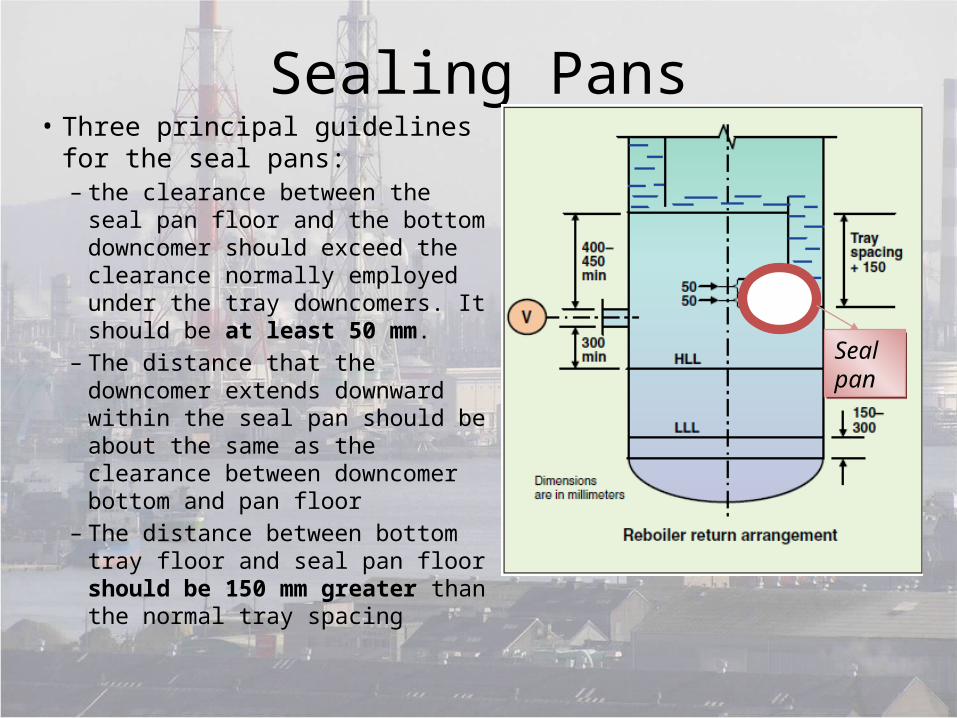
Sealing Pans• Three principal guidelines for the
seal pans:– the clearance between the seal
pan floor and the bottom downcomer should exceed the clearance normally employed under the tray downcomers. It should be at least 50 mm.
– The distance that the downcomer extends downward within the seal pan should be about the same as the clearance between downcomer bottom and pan floor
– The distance between bottom tray floor and seal pan floor should be 150 mm greater than the normal tray spacing
Seal panSeal pan
Tray Data Sheet
• For each tray section specify:– the vapor flow to the tray and the liquid flow from the tray.– The relevant temperatures,pressures, densities, viscosities
and surface tensions as applicable.
• Systems that foam a lot require appropriate downcomer design and tray spacing.
• The basic input for filling out the tray data sheet comes from the results of column simulations based on one of the widely available, proprietary software packages, along with mass and energy balances.

Additional Design Details
• A column data sheet provides the column vendor (which is not the tray vendor) with data on the column shell: its height, diameter, operating and design temperatures and pressures ,material of construction, corrosion allowance, nozzle details, provision of manways, and similar details.
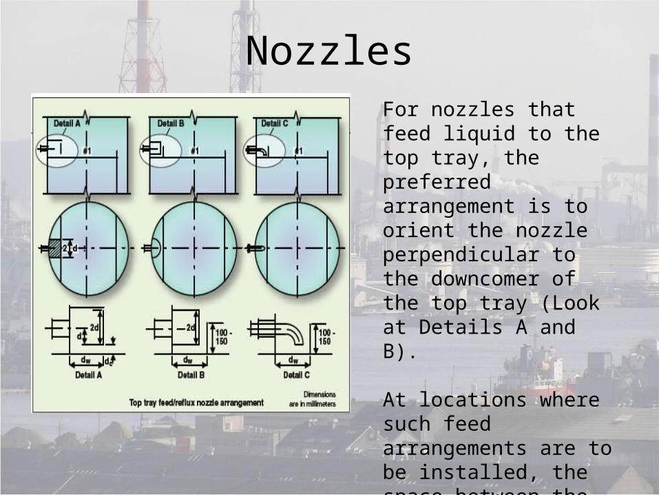
NozzlesFor nozzles that feed liquid to the top tray, the preferred arrangement is to orient the nozzle perpendicular to the downcomer of the top tray (Look at Details A and B).
At locations where such feed arrangements are to be installed, the space between the two trays should be at least 800 mm, to facilitate the installation
Column Manway
• Normal practice is to provide access to the column by specifying manways every 12 to 15 trays.
• At locations where the manways are to be included, the tray spacings need to be at least 900 mm.
• It is good engineering practice to install manways above feed trays, where the spacing must in any case be greater to accommodate the distributor pipes.
The Column Bottom
• The inlets for the bottom feed and the reboiler return lines alike should be above the high liquid level (HLL). The bottom of either pipe should beat least 300 mm above the HLL .
• The bottom feed and reboiler return should not impinge on the bottom seal pan, seal pan overflow, or the bottom downcomer.
• The tops of both pipes should be at least 400 to 450 mm below the bottom tray.
• Tangential bottom-feed and reboilerreturn nozzles should be avoided, since they impart a swirl on the sump and promote vortexing.

THE END