TRAX Flex HS User’s Manual LIMITED WARRANTY · TRAX Flex HS User’s Manual 1-2 1-3 What is the...
92
i
Transcript of TRAX Flex HS User’s Manual LIMITED WARRANTY · TRAX Flex HS User’s Manual 1-2 1-3 What is the...

i

TRAX Flex HS User’s Manual
ii iii
LIMITED WARRANTY
JAMAR Technologies, Inc. warrants the TRAX Flex HS against defects in material and workmanship for a period of one (1) year limited warranty on parts and one (1) year limited warranty on labor from the date of purchase. For information on extended warranty call 1-800-776-0940.
JAMAR Technologies, Inc. warrants each new instrument manufactured by the company to be free from defective material and workmanship and agrees to remedy any such defect. At its option, it may furnish a new part in exchange for any part of any instrument of its manufacture which, under normal installation, use and service discloses such defect. The instrument must be returned to our factory or authorized service agent intact, for examination, with all transportation charges prepaid.
This warranty does not extend to any products which have been subject to misuse, neglect, accident, vandalism or incorrect wiring not our own. This warranty does not extend to water damage caused by the use of faulty or improperly installed road tube or damage caused by improper installation in disregard of the instructions furnished by us. This warranty does not extend to products which have been repaired or altered outside our factory or authorized service agent. There is a 90 day warranty on the rechargeable battery of the TRAX.
In no event shall JAMAR Technologies, Inc. be liable for any damages arising from the use of this product including damages arising from the loss of information.
This warranty is in lieu of all other warranties expressed or implied and no representative or person is authorized to assume for us any other liability in connection with the sale or use of our products.
JAMAR Technologies, Inc. reserves the right to make improvements on the product and/or specifications at any time without notice.
Questions concerning this warranty or any JAMAR Technologies, Inc. product should be directed by mail or telephone to:
JAMAR Technologies, Inc.1500 Industry Road, Suite C
Hatfield, PA 19440215-361-2244
COPYRIGHT NOTICEThis manual is copyrighted. All rights are reserved. This document may not be, in whole or part, photocopied, reproduced, translated, or reduced to any electronic medium or machine readable form without prior consent, in writ-ing, from JAMAR Technologies, Inc.
Copyright 2008 by JAMAR Technologies, Inc.
TRAX Flex HS User’s Manual
ii iii
If you have any questions about the TRAX Flex HS that you cannot find answers for in this manual, there are several ways to get additional infor-mation.
On the Hardware Support section of our web site at:
www.jamartech.com
Contact us by e-mail at:
Contact us by phone at:
215-361-2244Monday - Friday 8:00 AM to 5:00 PM Eastern time
Volume 1.5 August 2008
TRAX Flex HS User’s Manual
iv v
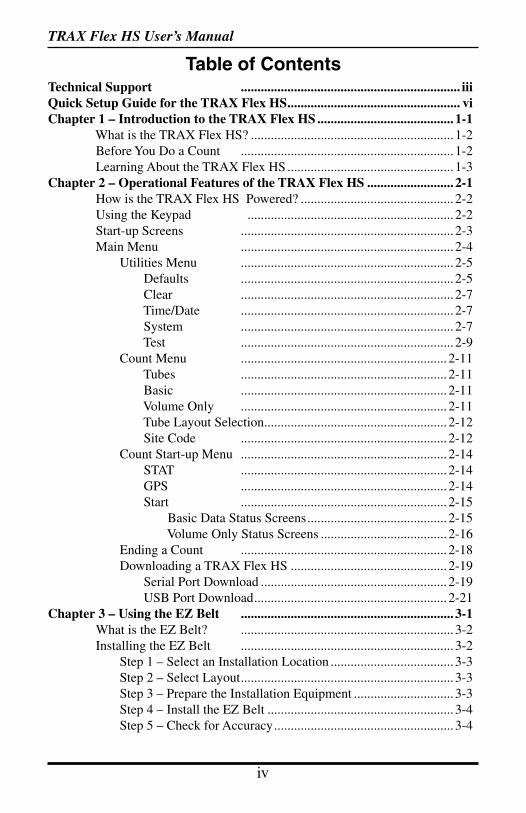
Technical Support .................................................................. iiiQuick Setup Guide for the TRAX Flex HS.................................................... viChapter 1 – Introduction to the TRAX Flex HS ......................................... 1-1 What is the TRAX Flex HS? ............................................................. 1-2 Before You Do a Count ................................................................ 1-2 Learning About the TRAX Flex HS .................................................. 1-3Chapter 2 – Operational Features of the TRAX Flex HS .......................... 2-1 How is the TRAX Flex HS Powered? .............................................. 2-2 Using the Keypad .............................................................. 2-2 Start-up Screens ................................................................ 2-3 Main Menu ................................................................ 2-4 Utilities Menu ................................................................ 2-5 Defaults ................................................................ 2-5 Clear ................................................................ 2-7 Time/Date ................................................................ 2-7 System ................................................................ 2-7 Test ................................................................ 2-9 Count Menu .............................................................. 2-11 Tubes .............................................................. 2-11 Basic .............................................................. 2-11 Volume Only .............................................................. 2-11 Tube Layout Selection....................................................... 2-12 Site Code .............................................................. 2-12 Count Start-up Menu .............................................................. 2-14 STAT .............................................................. 2-14 GPS .............................................................. 2-14 Start .............................................................. 2-15 Basic Data Status Screens.......................................... 2-15 Volume Only Status Screens ...................................... 2-16 Ending a Count .............................................................. 2-18 Downloading a TRAX Flex HS ............................................... 2-19 Serial Port Download ........................................................ 2-19 USB Port Download.......................................................... 2-21 Chapter 3 – Using the EZ Belt ................................................................ 3-1 What is the EZ Belt? ................................................................ 3-2 Installing the EZ Belt ................................................................ 3-2 Step 1 – Select an Installation Location ..................................... 3-3 Step 2 – Select Layout................................................................ 3-3 Step 3 – Prepare the Installation Equipment .............................. 3-3 Step 4 – Install the EZ Belt ........................................................ 3-4 Step 5 – Check for Accuracy...................................................... 3-4
Table of Contents
TRAX Flex HS User’s Manual
iv v
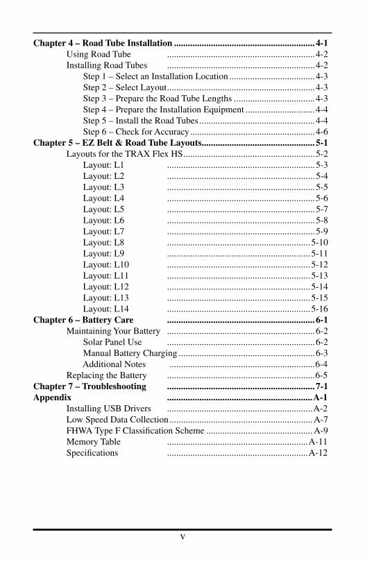
Chapter 4 – Road Tube Installation ............................................................. 4-1 Using Road Tube ................................................................ 4-2 Installing Road Tubes ................................................................ 4-2 Step 1 – Select an Installation Location ..................................... 4-3 Step 2 – Select Layout................................................................ 4-3 Step 3 – Prepare the Road Tube Lengths ................................... 4-3 Step 4 – Prepare the Installation Equipment .............................. 4-4 Step 5 – Install the Road Tubes .................................................. 4-4 Step 6 – Check for Accuracy...................................................... 4-6Chapter 5 – EZ Belt & Road Tube Layouts................................................. 5-1 Layouts for the TRAX Flex HS......................................................... 5-2 Layout: L1 ................................................................ 5-3 Layout: L2 ................................................................ 5-4 Layout: L3 ................................................................ 5-5 Layout: L4 ................................................................ 5-6 Layout: L5 ................................................................ 5-7 Layout: L6 ................................................................ 5-8 Layout: L7 ................................................................ 5-9 Layout: L8 .............................................................. 5-10 Layout: L9 .............................................................. 5-11 Layout: L10 .............................................................. 5-12 Layout: L11 .............................................................. 5-13 Layout: L12 .............................................................. 5-14 Layout: L13 .............................................................. 5-15 Layout: L14 .............................................................. 5-16Chapter 6 – Battery Care ................................................................ 6-1 Maintaining Your Battery ................................................................ 6-2 Solar Panel Use ................................................................ 6-2 Manual Battery Charging ........................................................... 6-3 Additional Notes ...............................................................6-4 Replacing the Battery ................................................................6-5Chapter 7 – Troubleshooting ................................................................ 7-1Appendix ...............................................................A-1 Installing USB Drivers ...............................................................A-2 Low Speed Data Collection.............................................................. A-7 FHWA Type F Classification Scheme .............................................. A-9 Memory Table .............................................................A-11 Specifications .............................................................A-12
TRAX Flex HS User’s Manual
vi 1-1
Quick Setup Guide for the TRAX Flex HS
1. Turn the TRAX Flex HS ON by pressing the POWER button.
2. On the Main Menu, check the battery voltage (bat:X.Xv). For longer studies (week or more) the voltage should be at least 6.4. It can be less for shorter counts, but should not be below 6.1.
3. TAB to Utils and press the DO key once. With Default flashing, press the DO key once.
4. TAB to Space and press the DO key once. Check the spacing currently set for the study. If you are using normal road tubes, the spacing should be set to 2.0 ft. If you are using the EZ Belt, the spacing should be set to 0.3 ft. Hit the DO key when your selection is correct.
5. Hit the DO key twice with Exit flashing to return to the main menu. The default tube spacing will remain stored in the TRAX for all future studies. You will not need to set it again unless you are going to use a different spacing.
6. From the Main Menu, press the DO key when Count is flashing.
7. Select the type of study you wish to do by using the TAB key and hitting DO when your selection is flashing. The options are Basic and Volume Only.
Basic: time-stamped raw data. This study gives you the greatest flexibility and, depending on the layout selected, can be used to get volume, class, speed and gap information. This is the selection that is most commonly used with the TRAX Flex HS and the one we recommend. Volume Only: axle or divide-by-two vehicle counting. This study type can be used if you are only interested in vehicle volumes. For Volume-Axle, each axle is counted. For Volume-Vehicle, every two axles is counted as one (divide-by-two technique).
8. After selecting your type of study, you will be prompted to select a tube layout. Refer to the descriptions on the TRAX Flex HS or to Chapter 5 for the appropriate selection. Layouts L5, L6, L10, L11 and L12 can be used to collect data for speed. class, gap and volume. The remaining layouts can provide only gap and volume data. TAB to your selection and press the DO key to select it.
9. You will then be prompted to select a site code. Press DO with Yes flashing to enter one or press DO with No flashing to not use a site code.
10. Press DO with Start flashing to begin your study!

TRAX Flex HS User’s Manual
vi 1-1
Chapter 1
Introductionto the
TRAX Flex HS
Chapter 1 — Introduction to the TRAX Flex HS
TRAX Flex HS User’s Manual
1-2 1-3
What is the TRAX Flex HS?The TRAX Flex HS Counter/Classifier is an automatic traffic recorder de-signed and built by JAMAR Technologies, Inc. It is designed for ease of use, but contains many options and features that are needed for comprehensive traffic data analysis.
The HS stands for 'high-speed', which best describes the processing power of this unit. With the TRAX Flex HS you can collect data than can be processed for volume, speed, class and gap using a tube spacing as small as four inches.
The TRAX Flex HS can store up to 150 different studies. It stores the type of study done, the date and time, a site code & GPS coordinates (if entered) and the data for the study. At any convenient time, you can transfer the data to your computer or PDA using either the RS-232 serial port or the USB port. Once the data is in the TRAXPro software, reports for volume, class, speed and gap can be generated.
Before You Do a CountBefore you attempt to collect important data with the TRAX Flex HS we strongly recommend that you familiarize yourself with both the operation of the TRAX and how to properly install your road tubes or EZ Belt. Few things are more frustrating than trying to resolve problems when working on a tight deadline or with critical data.
The next section provides a tutorial that walks you through the basics of setting up the TRAX and starting a count.
Whenever possible, we recommend that you perform a test count if you are new to the TRAX Flex HS or are planning to collect data that you have not in the past. This will help you become comfortable with the operation of the equipment and how the data is collected, which should make things easier when you have to do a real count.
TRAX Flex HS User’s Manual
1-2 1-3
Learning about the TRAX Flex HSThe remainder of this chapter provides a tutorial that will walk you through the basics of setting up the TRAX and starting a new study. Once you have completed this tutorial, you should have a good working knowledge of how the TRAX Flex HS operates.
At its heart, the TRAX is a very simple unit to set up and use. This tutorial will not attempt to cover every feature and option of the TRAX, just those that are most commonly used. If you would like more information on a specific feature that is not covered in this tutorial, refer to chapter 2, which provides details on all the features and options of the TRAX Flex.
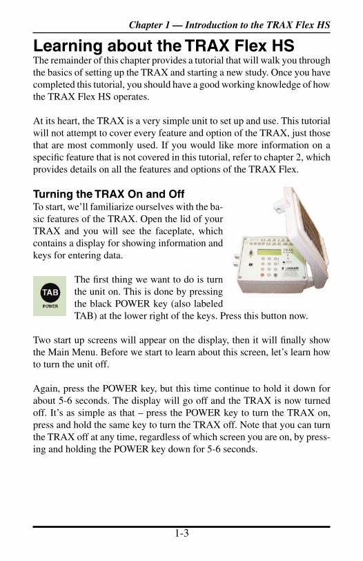
Turning the TRAX On and OffTo start, we’ll familiarize ourselves with the ba-sic features of the TRAX. Open the lid of your TRAX and you will see the faceplate, which contains a display for showing information and keys for entering data.
The first thing we want to do is turn the unit on. This is done by pressing the black POWER key (also labeled TAB) at the lower right of the keys. Press this button now.
Two start up screens will appear on the display, then it will finally show the Main Menu. Before we start to learn about this screen, let’s learn how to turn the unit off.
Again, press the POWER key, but this time continue to hold it down for about 5-6 seconds. The display will go off and the TRAX is now turned off. It’s as simple as that – press the POWER key to turn the TRAX on, press and hold the same key to turn the TRAX off. Note that you can turn the TRAX off at any time, regardless of which screen you are on, by press-ing and holding the POWER key down for 5-6 seconds.
Chapter 1 — Introduction to the TRAX Flex HS

TRAX Flex HS User’s Manual
1-4 1-5
Battery ConservationThe TRAX has a battery-saving feature that turns the display off if no keys have been pressed for 2 minutes. The TRAX is still on and run-ning, but the display has shut itself off to conserve power. When the TRAX goes into this conservation mode, you need only hit any of the keys on the keypad for the display to come back up.
Similarly, the TRAX has another feature that will turn itself off com-pletely if no keys are pressed for 10 minutes (if there is no count in progress, of course). If this occurs, you can press the POWER key and the TRAX will turn itself back on. The nice thing about this feature is that it will preserve the charge on the TRAX’s battery if the TRAX is accidently left turned on.
Now that we’re familiar with how to turn the TRAX off and on, let’s restart it and start looking at some of the features. Press the POWER key again to restart the TRAX and let it boot up to the Main Menu.
Menu NavigationThere are two keys on the keypad of the TRAX that are used to navigate through the various screens and select options. The black TAB key is used for navigation, while the red DO key is used to select an option. In general, you press the TAB key until the option you want is flashing, and then press the DO key to select the option. If you move the highlight too far and overshoot the desired option, just keep pressing the TAB key until it is re-selected. Let’s see how this works.
The Main Menu shows several options on the top line – Count, Utils and Stat. Notice that Count is flashing. This means that it is the currently active option. Now, press the TAB key once and notice that Utils is now flashing. Press it again and Stat is flashing. Press TAB again, and the display goes back to Count flashing. The TAB key is used to scroll through the various options shown on the display.
Press to move highlight
Press to select option
COUNT UTILS STAT :0 :0 TAB - NEXT DO - Select :0 Bat:6.4V :0
Main Menu with Count highlighted
TRAX Flex HS User’s Manual
1-4 1-5
Now, press TAB until Stat starts flashing again. With Stat flashing, press the DO key and hold it down.
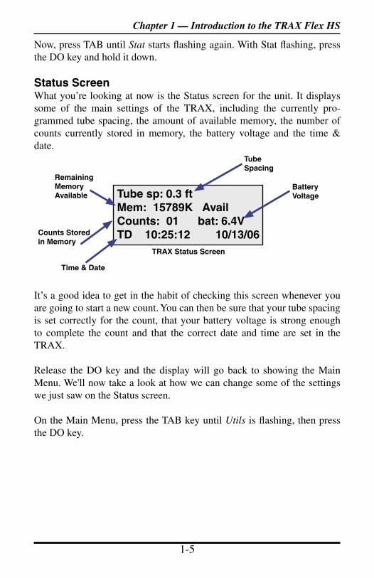
Status ScreenWhat you’re looking at now is the Status screen for the unit. It displays some of the main settings of the TRAX, including the currently pro-grammed tube spacing, the amount of available memory, the number of counts currently stored in memory, the battery voltage and the time & date.
It’s a good idea to get in the habit of checking this screen whenever you are going to start a new count. You can then be sure that your tube spacing is set correctly for the count, that your battery voltage is strong enough to complete the count and that the correct date and time are set in the TRAX.
Release the DO key and the display will go back to showing the Main Menu. We'll now take a look at how we can change some of the settings we just saw on the Status screen.
On the Main Menu, press the TAB key until Utils is flashing, then press the DO key.
Tube sp: 0.3 ftMem: 15789K AvailCounts: 01 bat: 6.4VTD 10:25:12 10/13/06
Time & Date
BatteryVoltage
Tube Spacing
Counts Stored in Memory
Remaining MemoryAvailable
Chapter 1 — Introduction to the TRAX Flex HS
TRAX Status Screen
TRAX Flex HS User’s Manual
1-6 1-7
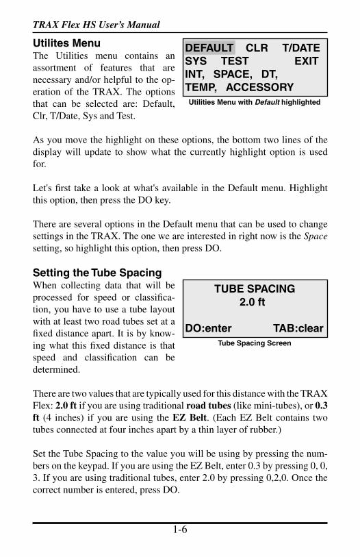
Utilites MenuThe Utilities menu contains an assortment of features that are necessary and/or helpful to the op-eration of the TRAX. The options that can be selected are: Default, Clr, T/Date, Sys and Test.
As you move the highlight on these options, the bottom two lines of the display will update to show what the currently highlight option is used for.
Let's first take a look at what's available in the Default menu. Highlight this option, then press the DO key.
There are several options in the Default menu that can be used to change settings in the TRAX. The one we are interested in right now is the Space setting, so highlight this option, then press DO.
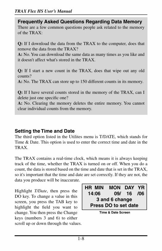
Setting the Tube SpacingWhen collecting data that will be processed for speed or classifica-tion, you have to use a tube layout with at least two road tubes set at a fixed distance apart. It is by know-ing what this fixed distance is that speed and classification can be determined.
There are two values that are typically used for this distance with the TRAX Flex: 2.0 ft if you are using traditional road tubes (like mini-tubes), or 0.3 ft (4 inches) if you are using the EZ Belt. (Each EZ Belt contains two tubes connected at four inches apart by a thin layer of rubber.)
Set the Tube Spacing to the value you will be using by pressing the num-bers on the keypad. If you are using the EZ Belt, enter 0.3 by pressing 0, 0, 3. If you are using traditional tubes, enter 2.0 by pressing 0,2,0. Once the correct number is entered, press DO.
TUBE SPACING 2.0 ft
DO:enter TAB:clearTube Spacing Screen
DEFAULT CLR T/DATESYS TEST EXITINT, SPACE, DT,TEMP, ACCESSORYUtilities Menu with Default highlighted

TRAX Flex HS User’s Manual
1-6 1-7
The other settings in the Defaults menu are ones that you probably won't ever need to change from their factory settings, so we won't go into them in this tutorial. Chapter 2 provides details on every setting in the TRAX, if you do ever need to change any of these values.
With Exit flashing, press the DO key and we'll return to the Utilites menu.
Clearing the Data MemoryThe second option listed in the Utilites menu is CLR, which stands for Clear. This option is used to clear the data memory of the TRAX.
When you do a count with the TRAX, that count stays in the memory of the TRAX until you clear the memory using this option. That's an impor-tant fact to remember, so we'll repeat it - when you do a count with the TRAX, that count stays in the memory of the TRAX until you clear the memory using this option.
Let's take a closer look at this process. Highlight CLR, then press the DO key.
If you are worried about losing your data by following the previous in-struction, don't be. When you select the CLR option, the TRAX does not immediately clear the memory. Instead, it brings up the first of two con-firmation screen that you must go through before the memory is actually cleared. This is designed to prevent you from accidentally clearing the memory. To clear the memory, you must confirm that that is what you want to do on both confirmation screens.
How often you should clear the memory is a matter of personal preference. We recommend that you clear the memory after you have downloaded your data to the computer and checked to make sure it looks okay. How-ever, some people like to leave the counts in the TRAX's memory for a while as a sort of a backup of the data. It's up to you to decide which you prefer.
Since we don't want to actually clear the memory at this point, press DO with Exit flashing to return to the Utilites menu.
Chapter 1 — Introduction to the TRAX Flex HS
TRAX Flex HS User’s Manual
1-8 1-9
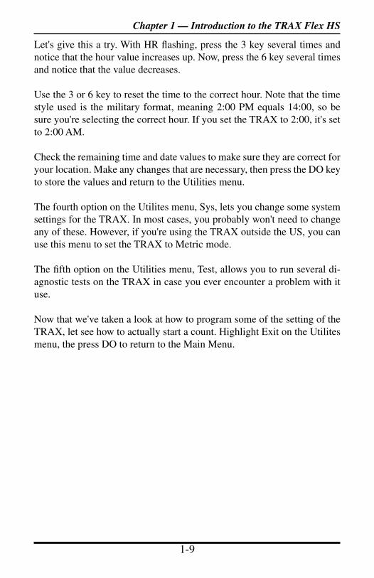
Setting the Time and DateThe third option listed in the Utilites menu is T/DATE, which stands for Time & Date. This option is used to enter the correct time and date in the TRAX.
The TRAX contains a real-time clock, which means it is always keeping track of the time, whether the TRAX is turned on or off. When you do a count, the data is stored based on the time and date that is set in the TRAX, so it's important that the time and date are set correctly. If they are not, the data you produce will be inaccurate.
Highlight T/Date, then press the DO key. To change a value in this screen, you press the TAB key to highlight the field you want to change. You then press the Change keys (numbers 3 and 6) to either scroll up or down through the values.
Frequently Asked Questions Regarding Data MemoryThere are a few common questions people ask related to the memory of the TRAX:
Q: If I download the data from the TRAX to the computer, does that remove the data from the TRAX?A: No. You can download the same data as many times as you like and it doesn't affect what's stored in the TRAX.
Q: If I start a new count in the TRAX, does that wipe out any old counts?A: No. The TRAX can store up to 150 different counts in its memory.
Q: If I have several counts stored in the memory of the TRAX, can I delete just one specific one?A: No. Clearing the memory deletes the entire memory. You cannot clear individual counts from the memory.
HR MIN MON DAY YR 14:06 09/ 16 /06
3 and 6 changePress DO to set date
Time & Date Screen
TRAX Flex HS User’s Manual
1-8 1-9
Chapter 1 — Introduction to the TRAX Flex HS
Let's give this a try. With HR flashing, press the 3 key several times and notice that the hour value increases up. Now, press the 6 key several times and notice that the value decreases.
Use the 3 or 6 key to reset the time to the correct hour. Note that the time style used is the military format, meaning 2:00 PM equals 14:00, so be sure you're selecting the correct hour. If you set the TRAX to 2:00, it's set to 2:00 AM.
Check the remaining time and date values to make sure they are correct for your location. Make any changes that are necessary, then press the DO key to store the values and return to the Utilities menu.
The fourth option on the Utilites menu, Sys, lets you change some system settings for the TRAX. In most cases, you probably won't need to change any of these. However, if you're using the TRAX outside the US, you can use this menu to set the TRAX to Metric mode.
The fifth option on the Utilities menu, Test, allows you to run several di-agnostic tests on the TRAX in case you ever encounter a problem with it use.
Now that we've taken a look at how to program some of the setting of the TRAX, let see how to actually start a count. Highlight Exit on the Utilites menu, the press DO to return to the Main Menu.
TRAX Flex HS User’s Manual
1-10 1-11
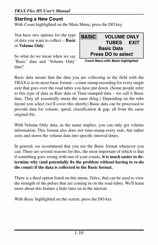
Starting a New CountWith Count highlighted on the Main Menu, press the DO key.
You have two options for the type of data you want to collect – Basic or Volume Only.
So what do we mean when we say ‘Basic’ data and ‘Volume Only’ data?
Basic data means that the data you are collecting in the field with the TRAX is in its most basic format – a time-stamp recording for every single axle that goes over the road tubes you have put down. (Some people refer to this type of data as Raw data or Time-stamped data – we call it Basic data. They all essentially mean the same thing.) Depending on the tube layout you select (we'll cover this shortly) Basic data can be processed to provide data for volume, speed, classification & gap, all from the same original file.
With Volume Only data, as the name implies, you can only get volume information. This format also does not time-stamp every axle, but rather sorts and stores the volume data into specific interval times.
In general, we recommend that you use the Basic format whenever you can. There are several reasons for this, the most important of which is that if something goes wrong with one of your counts, it is much easier to de-termine why (and potentially fix the problem without having to re-do the count) if the data is collected in the Basic format.
There is a third option listed on this menu, Tubes, that can be used to view the strength of the pulses that are coming in on the road tubes. We'll learn more about this feature a little later on in the tutorial.
With Basic highlighted on the screen, press the DO key.
BASIC VOLUME ONLY TUBES EXIT Basic Data Press DO to select
Count Menu with Basic highlighted
TRAX Flex HS User’s Manual
1-10 1-11
Chapter 1 — Introduction to the TRAX Flex HS
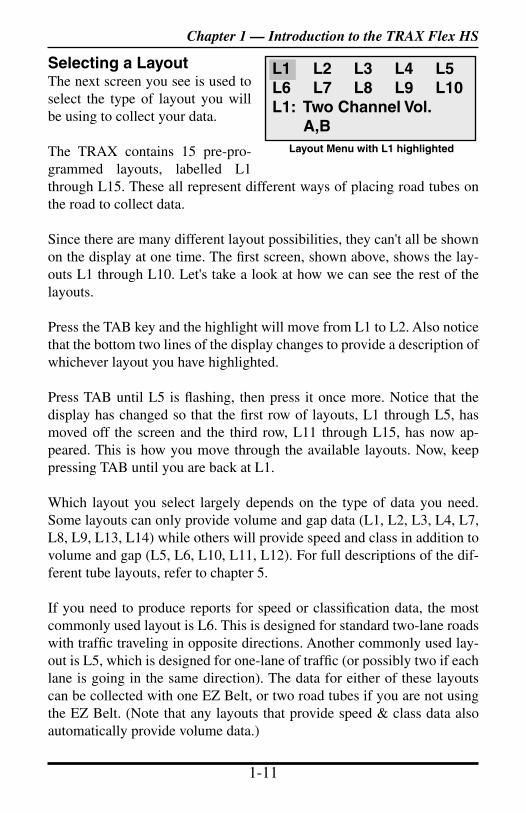
Selecting a LayoutThe next screen you see is used to select the type of layout you will be using to collect your data.
The TRAX contains 15 pre-pro-grammed layouts, labelled L1 through L15. These all represent different ways of placing road tubes on the road to collect data.
Since there are many different layout possibilities, they can't all be shown on the display at one time. The first screen, shown above, shows the lay-outs L1 through L10. Let's take a look at how we can see the rest of the layouts.
Press the TAB key and the highlight will move from L1 to L2. Also notice that the bottom two lines of the display changes to provide a description of whichever layout you have highlighted.
Press TAB until L5 is flashing, then press it once more. Notice that the display has changed so that the first row of layouts, L1 through L5, has moved off the screen and the third row, L11 through L15, has now ap-peared. This is how you move through the available layouts. Now, keep pressing TAB until you are back at L1.
Which layout you select largely depends on the type of data you need. Some layouts can only provide volume and gap data (L1, L2, L3, L4, L7, L8, L9, L13, L14) while others will provide speed and class in addition to volume and gap (L5, L6, L10, L11, L12). For full descriptions of the dif-ferent tube layouts, refer to chapter 5.
If you need to produce reports for speed or classification data, the most commonly used layout is L6. This is designed for standard two-lane roads with traffic traveling in opposite directions. Another commonly used lay-out is L5, which is designed for one-lane of traffic (or possibly two if each lane is going in the same direction). The data for either of these layouts can be collected with one EZ Belt, or two road tubes if you are not using the EZ Belt. (Note that any layouts that provide speed & class data also automatically provide volume data.)
L1 L2 L3 L4 L5 L6 L7 L8 L9 L10 L1: Two Channel Vol. A,B
Layout Menu with L1 highlighted
TRAX Flex HS User’s Manual
1-12 1-13
For this tutorial, we'll select the L6 layout, so press the TAB key until L6 is flashing, then press DO.
The next screen gives you the option to enter a Site Code for your count. This feature allows you to enter information specific to where the study was done, such as street names, location codes, etc. If you do a lot of counts at different locations, using Site Codes can help you keep track of them all. We won't use one for this tutorial, so press TAB to highlight NO, the press DO.
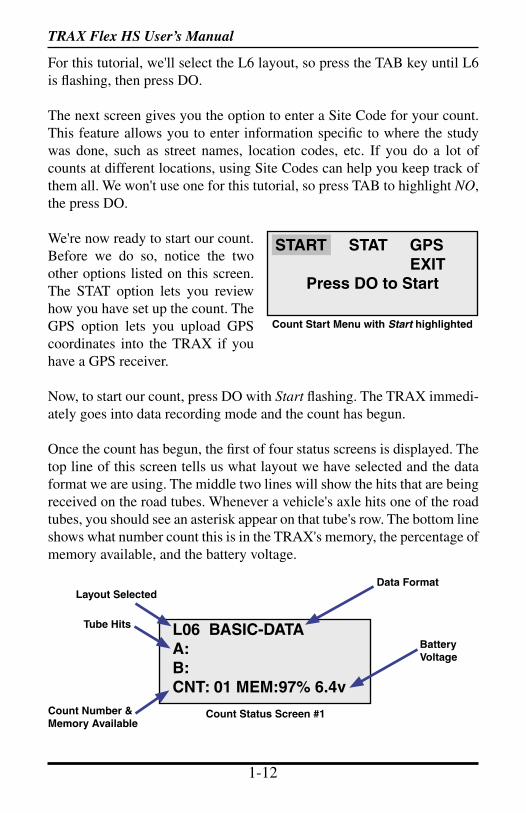
We're now ready to start our count. Before we do so, notice the two other options listed on this screen. The STAT option lets you review how you have set up the count. The GPS option lets you upload GPS coordinates into the TRAX if you have a GPS receiver.
Now, to start our count, press DO with Start flashing. The TRAX immedi-ately goes into data recording mode and the count has begun.
Once the count has begun, the first of four status screens is displayed. The top line of this screen tells us what layout we have selected and the data format we are using. The middle two lines will show the hits that are being received on the road tubes. Whenever a vehicle's axle hits one of the road tubes, you should see an asterisk appear on that tube's row. The bottom line shows what number count this is in the TRAX's memory, the percentage of memory available, and the battery voltage.
START STAT GPS EXIT
Press DO to Start
Count Start Menu with Start highlighted
L06 BASIC-DATAA:B:CNT: 01 MEM:97% 6.4v
Count Status Screen #1
Layout SelectedData Format
BatteryVoltage
Count Number &Memory Available
Tube Hits
TRAX Flex HS User’s Manual
1-12 1-13
Chapter 1 — Introduction to the TRAX Flex HS
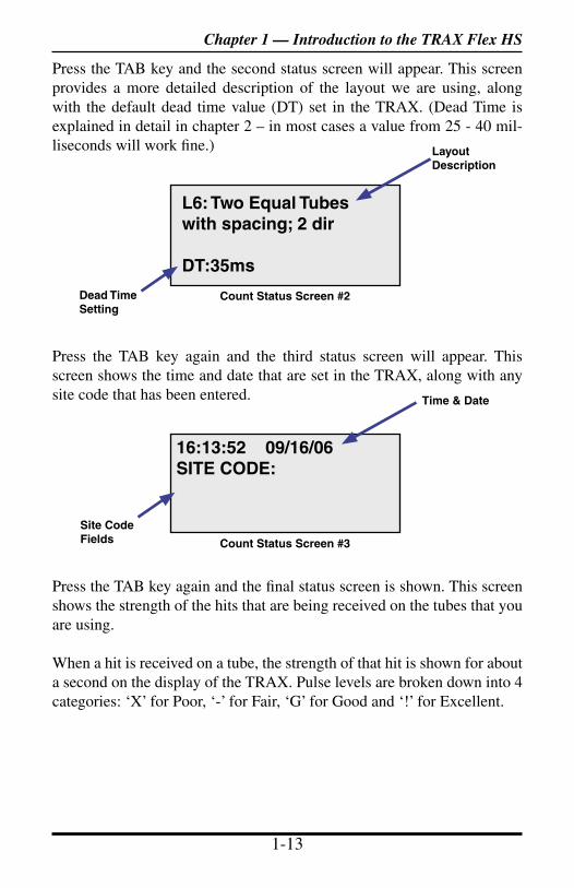
Press the TAB key and the second status screen will appear. This screen provides a more detailed description of the layout we are using, along with the default dead time value (DT) set in the TRAX. (Dead Time is explained in detail in chapter 2 – in most cases a value from 25 - 40 mil-liseconds will work fine.)
Press the TAB key again and the third status screen will appear. This screen shows the time and date that are set in the TRAX, along with any site code that has been entered.
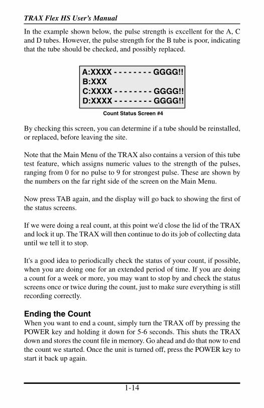
Press the TAB key again and the final status screen is shown. This screen shows the strength of the hits that are being received on the tubes that you are using.
When a hit is received on a tube, the strength of that hit is shown for about a second on the display of the TRAX. Pulse levels are broken down into 4 categories: ‘X’ for Poor, ‘-’ for Fair, ‘G’ for Good and ‘!’ for Excellent.
L6: Two Equal Tubes with spacing; 2 dir
DT:35ms
Count Status Screen #2Dead TimeSetting
LayoutDescription
16:13:52 09/16/06SITE CODE:
Count Status Screen #3
Site Code Fields
Time & Date
TRAX Flex HS User’s Manual
1-14 1-15
In the example shown below, the pulse strength is excellent for the A, C and D tubes. However, the pulse strength for the B tube is poor, indicating that the tube should be checked, and possibly replaced.
By checking this screen, you can determine if a tube should be reinstalled, or replaced, before leaving the site.
Note that the Main Menu of the TRAX also contains a version of this tube test feature, which assigns numeric values to the strength of the pulses, ranging from 0 for no pulse to 9 for strongest pulse. These are shown by the numbers on the far right side of the screen on the Main Menu.
Now press TAB again, and the display will go back to showing the first of the status screens.
If we were doing a real count, at this point we'd close the lid of the TRAX and lock it up. The TRAX will then continue to do its job of collecting data until we tell it to stop.
It's a good idea to periodically check the status of your count, if possible, when you are doing one for an extended period of time. If you are doing a count for a week or more, you may want to stop by and check the status screens once or twice during the count, just to make sure everything is still recording correctly.
Ending the CountWhen you want to end a count, simply turn the TRAX off by pressing the POWER key and holding it down for 5-6 seconds. This shuts the TRAX down and stores the count file in memory. Go ahead and do that now to end the count we started. Once the unit is turned off, press the POWER key to start it back up again.
A:XXXX - - - - - - - - GGGG!! B:XXX C:XXXX - - - - - - - - GGGG!! D:XXXX - - - - - - - - GGGG!!
Count Status Screen #4
TRAX Flex HS User’s Manual
1-14 1-15
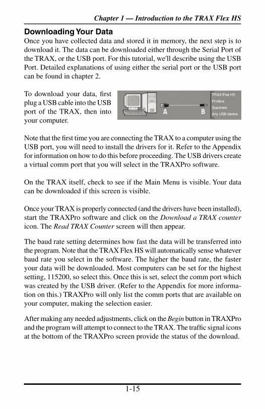
Downloading Your DataOnce you have collected data and stored it in memory, the next step is to download it. The data can be downloaded either through the Serial Port of the TRAX, or the USB port. For this tutorial, we'll describe using the USB Port. Detailed explanations of using either the serial port or the USB port can be found in chapter 2.
To download your data, first plug a USB cable into the USB port of the TRAX, then into your computer.
Note that the first time you are connecting the TRAX to a computer using the USB port, you will need to install the drivers for it. Refer to the Appendix for information on how to do this before proceeding. The USB drivers create a virtual comm port that you will select in the TRAXPro software.
On the TRAX itself, check to see if the Main Menu is visible. Your data can be downloaded if this screen is visible.
Once your TRAX is properly connected (and the drivers have been installed), start the TRAXPro software and click on the Download a TRAX counter icon. The Read TRAX Counter screen will then appear.
The baud rate setting determines how fast the data will be transferred into the program. Note that the TRAX Flex HS will automatically sense whatever baud rate you select in the software. The higher the baud rate, the faster your data will be downloaded. Most computers can be set for the highest setting, 115200, so select this. Once this is set, select the comm port which was created by the USB driver. (Refer to the Appendix for more informa-tion on this.) TRAXPro will only list the comm ports that are available on your computer, making the selection easier.
After making any needed adjustments, click on the Begin button in TRAXPro and the program will attempt to connect to the TRAX. The traffic signal icons at the bottom of the TRAXPro screen provide the status of the download.
Chapter 1 — Introduction to the TRAX Flex HS
TRAX Flex HS User’s Manual
1-16 2-1
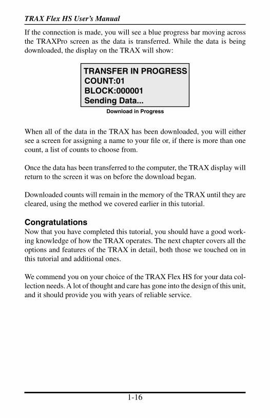
If the connection is made, you will see a blue progress bar moving across the TRAXPro screen as the data is transferred. While the data is being downloaded, the display on the TRAX will show:
When all of the data in the TRAX has been downloaded, you will either see a screen for assigning a name to your file or, if there is more than one count, a list of counts to choose from.
Once the data has been transferred to the computer, the TRAX display will return to the screen it was on before the download began.
Downloaded counts will remain in the memory of the TRAX until they are cleared, using the method we covered earlier in this tutorial.
CongratulationsNow that you have completed this tutorial, you should have a good work-ing knowledge of how the TRAX operates. The next chapter covers all the options and features of the TRAX in detail, both those we touched on in this tutorial and additional ones.
We commend you on your choice of the TRAX Flex HS for your data col-lection needs. A lot of thought and care has gone into the design of this unit, and it should provide you with years of reliable service.
TRANSFER IN PROGRESS COUNT:01 BLOCK:000001 Sending Data...
Download in Progress

TRAX Flex HS User’s Manual
1-16 2-1
Operational Features
of theTRAX Flex HS
Chapter 2
Chapter 2 — Operational Features of the TRAX Flex HS
TRAX Flex HS User’s Manual
2-2 2-3
How is the TRAX Flex HS powered?The TRAX Flex HS is powered by a rechargeable lead gel battery. The solar panel also provides power when in the field, which extends the time before the battery needs to be recharged. Depending upon use, batteries may last for several months before they need to be recharged manually.
The TRAX Flex HS displays the battery voltage when it is first turned on. This allows you to determine if there is enough battery power to complete a study. Generally, battery voltage should register at 6.3 VDC or higher for a full charge.
Keeping your battery properly charged is very important. The rechargeable battery will begin to decay and become less effective if it is allowed to fall below 5.9 volts. To avoid having to replace your battery prematurely, keep it consistently charged. A well-maintained battery will last for years without having to be replaced. Refer to Chapter 6 Battery Care for more information on battery maintenance.
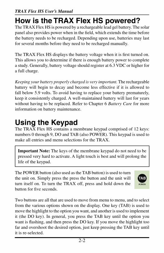
Using the KeypadThe TRAX Flex HS contains a membrane keypad comprised of 12 keys: numbers 0 through 9, DO and TAB (also POWER). This keypad is used to make all entries and menu selections for the TRAX.
Important Note: The keys of the membrane keypad do not need to be pressed very hard to activate. A light touch is best and will prolong the life of the keypad.
The POWER button (also used as the TAB button) is used to turn the unit on. Simply press the press the button and the unit will turn itself on. To turn the TRAX off, press and hold down the button for five seconds.
Two buttons are all that are used to move from menu to menu, and to select from the various options shown on the display. One key (TAB) is used to move the highlight to the option you want, and another is used to implement it (the DO key). In general, you press the TAB key until the option you want is flashing, and then press the DO key. If you move the highlight too far and overshoot the desired option, just keep pressing the TAB key until it is re-selected.
TRAX Flex HS User’s Manual
2-2 2-3
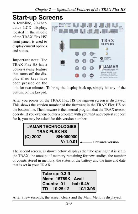
Start-up ScreensA four-line, 20-char-acter LCD display, located in the middle of the TRAX Flex HS’ front panel, is used to display current options and status.
Important note: The TRAX Flex HS has a power-saving feature that turns off the dis-play if no keys have been pressed on the unit for two minutes. To bring the display back up, simply hit any of the buttons on the keypad.
After you power on the TRAX Flex HS the sign-on screen is displayed. This shows the version number of the firmware in the TRAX Flex HS on the bottom line. The firmware is the internal program that the TRAX uses to operate. If you ever encounter a problem with your unit and request support for it, you may be asked for this version number.
The second screen, as shown below, displays the tube spacing that is set in the TRAX, the amount of memory remaining for new studies, the number of counts stored in memory, the status of the battery and the time and date that is set in your TRAX.
After a few seconds, the screen clears and the Main Menu is displayed.
Tube sp: 0.3 ftMem: 15789K AvailCounts: 01 bat: 6.4VTD 10:25:12 10/13/06
JAMAR TECHNOLOGIESTRAX FLEX HS
(C) 2007 SN:000000 V: 1.0.01 Firmware version
Chapter 2 — Operational Features of the TRAX Flex HS
TRAX Flex HS User’s Manual
2-4 2-5
Main Menu
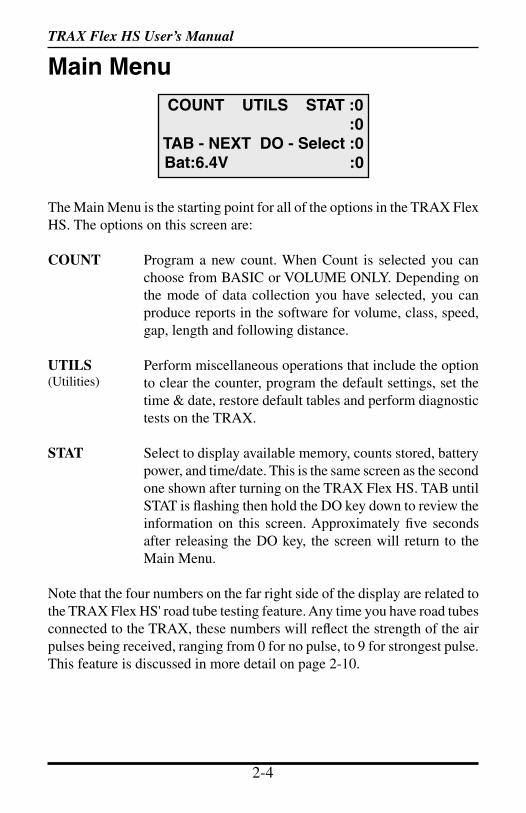
The Main Menu is the starting point for all of the options in the TRAX Flex HS. The options on this screen are:
COUNT Program a new count. When Count is selected you can choose from BASIC or VOLUME ONLY. Depending on the mode of data collection you have selected, you can produce reports in the software for volume, class, speed, gap, length and following distance.
UTILS Perform miscellaneous operations that include the option to clear the counter, program the default settings, set the time & date, restore default tables and perform diagnostic tests on the TRAX.
STAT Select to display available memory, counts stored, battery power, and time/date. This is the same screen as the second one shown after turning on the TRAX Flex HS. TAB until STAT is flashing then hold the DO key down to review the information on this screen. Approximately five seconds after releasing the DO key, the screen will return to the Main Menu.
Note that the four numbers on the far right side of the display are related to the TRAX Flex HS' road tube testing feature. Any time you have road tubes connected to the TRAX, these numbers will reflect the strength of the air pulses being received, ranging from 0 for no pulse, to 9 for strongest pulse. This feature is discussed in more detail on page 2-10.
COUNT UTILS STAT :0 :0 TAB - NEXT DO - Select :0 Bat:6.4V :0
(Utilities)
TRAX Flex HS User’s Manual
2-4 2-5
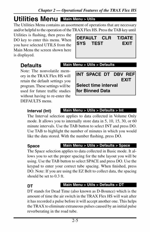
Utilities MenuThe Utilities Menu contains an assortment of operations that are necessary and/or helpful to the operation of the TRAX Flex HS. Press the TAB key until Utilities is flashing, then press the DO key to enter this menu. When you have selected UTILS from the Main Menu the screen shown here is displayed.
DefaultsNote: The nonvolatile mem-ory in the TRAX Flex HS will retain the default settings you program. These settings will be used for future traffic studies without having to re-enter the DEFAULTS menu.
Interval (Int)The Interval selection applies to data collected in Volume Only mode. It allows you to internally store data in 5, 10, 15, 30, or 60 minute intervals. Use the TAB button to select INT and press DO. Use TAB to highlight the number of minutes in which you would like the data stored. With the number flashing, press DO.
SpaceThe Space selection applies to data collected in Basic mode. It al-lows you to set the proper spacing for the tube layout you will be using. Use the TAB button to select SPACE and press DO. Use the keypad to enter your correct tube spacing. When finished, press DO. Note: If you are using the EZ Belt to collect data, the spacing should be set to 0.3 ft.
DTDT stands for Dead Time (also known as D-Bounce) which is the amount of time the air switch in the TRAX Flex HS will wait after it has recorded a pulse before it will accept another one. This helps the TRAX to eliminate extraneous pulses caused by an initial pulse reverberating in the road tube.
DEFAULT CLR T/DATESYS TEST EXIT
Main Menu > Utils
INT SPACE DT DBV REF EXIT Select time interval for Binned Data
Main Menu > Utils > Defaults
Main Menu > Utils > Defaults > Int
Main Menu > Utils > Defaults > Space
Main Menu > Utils > Defaults > DT
Chapter 2 — Operational Features of the TRAX Flex HS
TRAX Flex HS User’s Manual
2-6 2-7
To set the DT, use the TAB button to select DT and press DO. Use the keypad to enter in the DT and press DO when completed.
Typically, this value is set for 35 milliseconds, which will give good results on most traffic travelling at speeds from 10 to 70 mph. If you are recording traffic at faster speeds, you may want to lower the DT. At slower speeds, a higher DT can be used. Refer to the Appendix for more information.
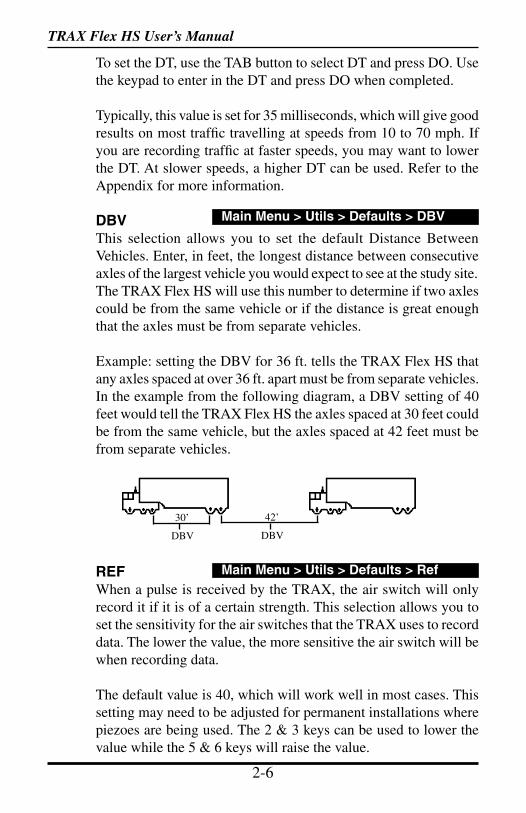
DBVThis selection allows you to set the default Distance Between Vehicles. Enter, in feet, the longest distance between consecutive axles of the largest vehicle you would expect to see at the study site. The TRAX Flex HS will use this number to determine if two axles could be from the same vehicle or if the distance is great enough that the axles must be from separate vehicles.
Example: setting the DBV for 36 ft. tells the TRAX Flex HS that any axles spaced at over 36 ft. apart must be from separate vehicles. In the example from the following diagram, a DBV setting of 40 feet would tell the TRAX Flex HS the axles spaced at 30 feet could be from the same vehicle, but the axles spaced at 42 feet must be from separate vehicles.
REFWhen a pulse is received by the TRAX, the air switch will only record it if it is of a certain strength. This selection allows you to set the sensitivity for the air switches that the TRAX uses to record data. The lower the value, the more sensitive the air switch will be when recording data.
The default value is 40, which will work well in most cases. This setting may need to be adjusted for permanent installations where piezoes are being used. The 2 & 3 keys can be used to lower the value while the 5 & 6 keys will raise the value.
Main Menu > Utils > Defaults > DBV
DBV DBV
30’ 42’
Main Menu > Utils > Defaults > Ref
TRAX Flex HS User’s Manual
2-6 2-7
Clear (CLR)The Clear option allows you to clear the memory of all data. You are given two chances to change your mind before data is removed from the nonvolatile memory.
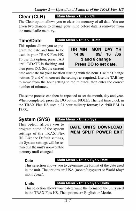
Time/DateThis option allows you to pro-gram the date and time to be used in your TRAX Flex HS. To use this option, press TAB until T/DATE is flashing and then press DO. Set the current time and date for your location starting with the hour. Use the Change buttons (3 and 6) to correct the settings as required. Use the TAB key to move from the hour setting to the minutes, then enter the correct number of minutes.
The same process can then be repeated to set the month, day and year. When completed, press the DO button. NOTE: The real time clock in the TRAX Flex HS uses a 24-hour military format; i.e. 5:00 P.M. is 17:00.
System (SYS)This option allows you to program some of the system settings of the TRAX Flex HS. Like the Default settings, the System settings will be re-tained in the unit’s non-volatile memory until changed.
DateThis selection allows you to determine the format of the date used in the unit. The options are USA (month/day/year) or World (day/month/year).
UnitsThis selection allows you to determine the format of the units used in the TRAX Flex HS. The options are English or Metric.
HR MIN MON DAY YR 14:06 09/ 16 /06
3 and 6 changePress DO to set date.
Main Menu > Utils > T/Date
DATE UNITS DOWNLOAD MEM SPLIT POWER EXIT
Main Menu > Utils > Sys
Main Menu > Utils > Sys > Date
Main Menu > Utils > Sys > Units
Main Menu > Utils > Clr
Chapter 2 — Operational Features of the TRAX Flex HS
TRAX Flex HS User’s Manual
2-8 2-9
DownloadThis selection allows you to determine how the TRAX should act if you download data while a study is in progress. The options are to Stop the current study and download its data or to Continue the current study while downloading older studies. Note that with the Continue option, the data stored in the currently running study will not be included in the download.
MemThis selection allows you to determine how the TRAX should respond if the memory is filled. The options are to Stop recording data or to Overwrite the beginning of the memory. In most cases you will never come close to filling the entire memory of the unit. The TRAX Flex HS’ 16 MB of internal memory will record over 6 million vehicles before the memory is filled.
SplitThis selection allows you to determine whether data should be recorded in continuous mode or if a new file should be started at midnight every day. The Never option tells the unit to never split the study. The Daily option tells it to split the study on a day by day basis, and is normally only used if the TRAX is set up at a permanent location, or if data is being retrieved while the unit is still recording data. The Weekly option tells it to split the study on a weekly basis, starting at 12 AM Sunday.
PowerThis selection allows you to set two options related to battery conservation issues.
The Idle setting is used to tell the TRAX whether or not it should turn itself off if no keys have been pressed for 10 minutes and there is no count in progress. If this option is enabled, the TRAX will shut itself down to save the battery. We recommend enabling this feature, as it prevents the battery from draining if the unit is accidentally left on.
The Battery setting is used to tell the TRAX whether or not it should turn itself off, even if a count is in progress, if the battery voltage falls to 5.7 volts or lower. If this option is enabled, the
Main Menu > Utils > Sys > Download
Main Menu > Utils > Sys > Power
Main Menu > Utils > Sys > Mem
Main Menu > Utils > Sys > Split
TRAX Flex HS User’s Manual
2-8 2-9
TRAX will shut itself down when the battery falls to 5.7 volts. If this option is disabled, the TRAX will continue to run even if the battery voltage gets low.
How you set this option depends on your preference. If you'd prefer to preserve your battery, even if it means shutting down the TRAX during a count, enable this setting. If you would rather have the TRAX continue running, and possibly complete a count even if the battery voltage gets low, disable this setting.
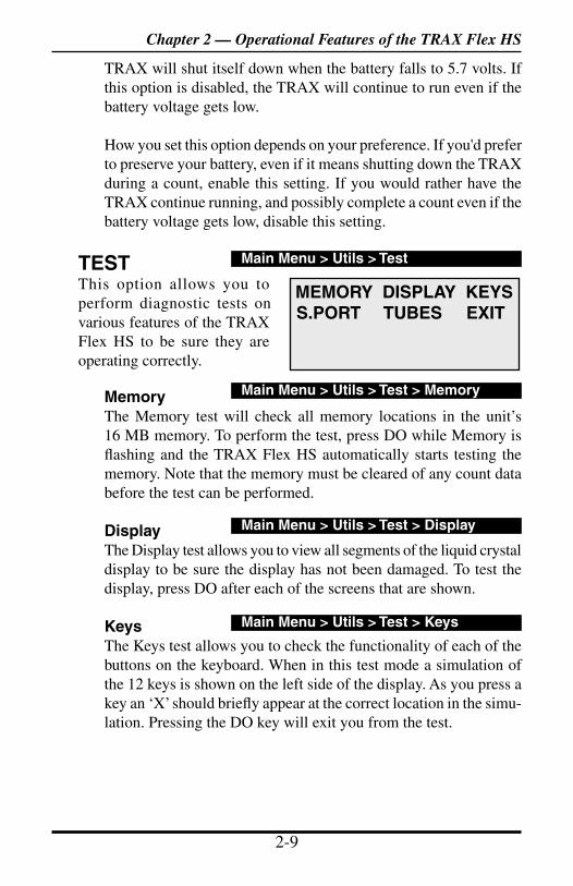
TESTThis option allows you to perform diagnostic tests on various features of the TRAX Flex HS to be sure they are operating correctly.
MemoryThe Memory test will check all memory locations in the unit’s 16 MB memory. To perform the test, press DO while Memory is flashing and the TRAX Flex HS automatically starts testing the memory. Note that the memory must be cleared of any count data before the test can be performed.
DisplayThe Display test allows you to view all segments of the liquid crystal display to be sure the display has not been damaged. To test the display, press DO after each of the screens that are shown.
KeysThe Keys test allows you to check the functionality of each of the buttons on the keyboard. When in this test mode a simulation of the 12 keys is shown on the left side of the display. As you press a key an ‘X’ should briefly appear at the correct location in the simu-lation. Pressing the DO key will exit you from the test.
MEMORY DISPLAY KEYS S.PORT TUBES EXIT
Main Menu > Utils > Test
Main Menu > Utils > Test > Memory
Main Menu > Utils > Test > Display
Main Menu > Utils > Test > Keys
Chapter 2 — Operational Features of the TRAX Flex HS
TRAX Flex HS User’s Manual
2-10 2-11
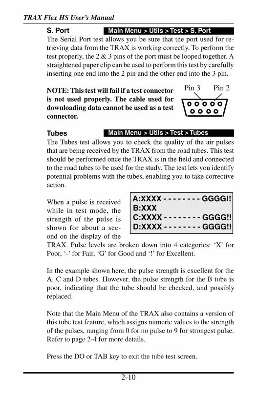
S. PortThe Serial Port test allows you be sure that the port used for re-trieving data from the TRAX is working correctly. To perform the test properly, the 2 & 3 pins of the port must be looped together. A straightened paper clip can be used to perform this test by carefully inserting one end into the 2 pin and the other end into the 3 pin.
NOTE: This test will fail if a test connector is not used properly. The cable used for downloading data cannot be used as a test connector.
TubesThe Tubes test allows you to check the quality of the air pulses that are being received by the TRAX from the road tubes. This test should be performed once the TRAX is in the field and connected to the road tubes to be used for the study. The test lets you identify potential problems with the tubes, enabling you to take corrective action.
When a pulse is received while in test mode, the strength of the pulse is shown for about a sec-ond on the display of the TRAX. Pulse levels are broken down into 4 categories: ‘X’ for Poor, ‘-’ for Fair, ‘G’ for Good and ‘!’ for Excellent.
In the example shown here, the pulse strength is excellent for the A, C and D tubes. However, the pulse strength for the B tube is poor, indicating that the tube should be checked, and possibly replaced.
Note that the Main Menu of the TRAX also contains a version of this tube test feature, which assigns numeric values to the strength of the pulses, ranging from 0 for no pulse to 9 for strongest pulse. Refer to page 2-4 for more details.
Press the DO or TAB key to exit the tube test screen.
Main Menu > Utils > Test > Tubes
A:XXXX - - - - - - - - GGGG!! B:XXX C:XXXX - - - - - - - - GGGG!! D:XXXX - - - - - - - - GGGG!!
Main Menu > Utils > Test > S. Port
Pin 3 Pin 2
TRAX Flex HS User’s Manual
2-10 2-11
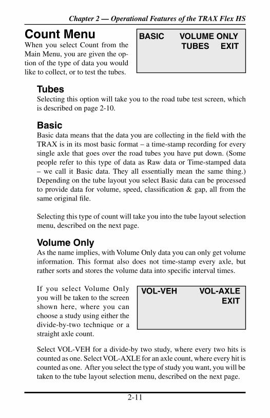
Count MenuWhen you select Count from the Main Menu, you are given the op-tion of the type of data you would like to collect, or to test the tubes.
TubesSelecting this option will take you to the road tube test screen, which is described on page 2-10.
BasicBasic data means that the data you are collecting in the field with the TRAX is in its most basic format – a time-stamp recording for every single axle that goes over the road tubes you have put down. (Some people refer to this type of data as Raw data or Time-stamped data – we call it Basic data. They all essentially mean the same thing.) Depending on the tube layout you select Basic data can be processed to provide data for volume, speed, classification & gap, all from the same original file. Selecting this type of count will take you into the tube layout selection menu, described on the next page.
Volume OnlyAs the name implies, with Volume Only data you can only get volume information. This format also does not time-stamp every axle, but rather sorts and stores the volume data into specific interval times.
If you select Volume Only you will be taken to the screen shown here, where you can choose a study using either the divide-by-two technique or a straight axle count.
Select VOL-VEH for a divide-by two study, where every two hits is counted as one. Select VOL-AXLE for an axle count, where every hit is counted as one. After you select the type of study you want, you will be taken to the tube layout selection menu, described on the next page.
BASIC VOLUME ONLY TUBES EXIT
VOL-VEH VOL-AXLE EXIT
Chapter 2 — Operational Features of the TRAX Flex HS
TRAX Flex HS User’s Manual
2-12 2-13
Important note: In general, we recommend that you use the Basic format whenever you can. There are several reasons for this, the most important of which is that if something goes wrong with one of your counts, it is much easier to determine why (and potentially fix the problem without having to re-do the count) if the data is collected in the Basic format.
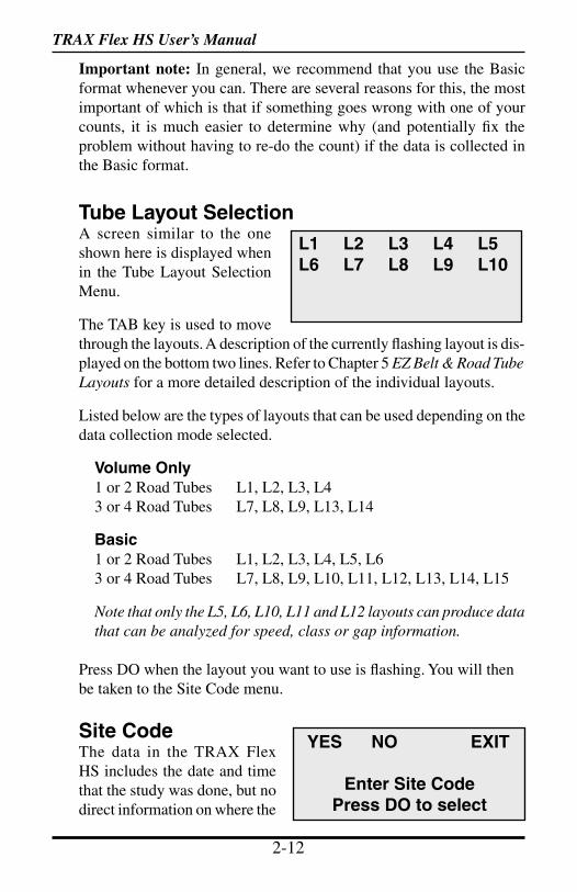
Tube Layout SelectionA screen similar to the one shown here is displayed when in the Tube Layout Selection Menu.
The TAB key is used to move through the layouts. A description of the currently flashing layout is dis-played on the bottom two lines. Refer to Chapter 5 EZ Belt & Road Tube Layouts for a more detailed description of the individual layouts.
Listed below are the types of layouts that can be used depending on the data collection mode selected.
Volume Only1 or 2 Road Tubes L1, L2, L3, L4 3 or 4 Road Tubes L7, L8, L9, L13, L14
Basic1 or 2 Road Tubes L1, L2, L3, L4, L5, L63 or 4 Road Tubes L7, L8, L9, L10, L11, L12, L13, L14, L15
Note that only the L5, L6, L10, L11 and L12 layouts can produce data that can be analyzed for speed, class or gap information.
Press DO when the layout you want to use is flashing. You will then be taken to the Site Code menu.
Site CodeThe data in the TRAX Flex HS includes the date and time that the study was done, but no direct information on where the
YES NO EXIT
Enter Site CodePress DO to select
L1 L2 L3 L4 L5 L6 L7 L8 L9 L10
TRAX Flex HS User’s Manual
2-12 2-13
study was done (unless GPS coordinates have been uploaded). Use of the Site Code is a way for you to identify the assigned count location.
To enter a Site Code, press DO while YES is flashing. You then have the option of using either a numeric (numbers only) site code or an alpha-numeric (numbers, letters and symbols) site code.
Numeric Site CodeNumeric site codes can be one or two lines, with up to 20 characters on each line. Enter the value for the first line of the site code using the numbered key on the TRAX. Once done, press DO to move to the second line. Once the second line has been entered press DO and the code is stored. You are then returned to the Site Code selection screen, with the code you entered shown. Select OK to proceed to the Count Start-Up menu.
Alpha-numeric Site CodeAlpha-numeric site codes can be one or two lines, with up to 20 characters on each line. The alpha-numeric code can use numbers, lower case letters, upper case letters and/or symbols. Use of an al-pha-numeric site code allows you to include street names or other text as part of your identification information.
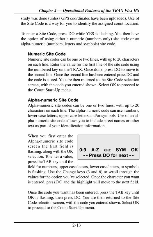
When you first enter the Alpha-numeric site code screen the first field is flashing, along with the OK selection. To enter a value, press the TAB key until the field for numbers, upper case letters, lower case letters, or symbols is flashing. Use the Change keys (3 and 6) to scroll through the values for the option you’ve selected. Once the character you want is entered, press DO and the highlight will move to the next field.
Once the code you want has been entered, press the TAB key until OK is flashing, then press DO. You are then returned to the Site Code selection screen, with the code you entered shown. Select OK to proceed to the Count Start-Up menu.
0-9 A-Z a-z SYM OK - - Press DO for next - -
Chapter 2 — Operational Features of the TRAX Flex HS
TRAX Flex HS User’s Manual
2-14 2-15
START STAT GPS EXIT
Press DO to Start
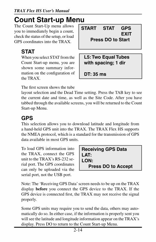
Count Start-up MenuThe Count Start-Up menu allows you to immediately begin a count, check the status of the setup, or load GPS coordinates into the TRAX.
STATWhen you select STAT from the Count Start-up menu, you are shown some summary infor-mation on the configuration of the TRAX.
The first screen shows the tube layout selection and the Dead Time setting. Press the TAB key to see the current date and time, as well as the Site Code. After you have tabbed through the available screens, you will be returned to the Count Start-up Menu.
GPSThis selection allows you to download latitude and longitude from a hand-held GPS unit into the TRAX. The TRAX Flex HS supports the NMEA protocol, which is a standard for the transmission of GPS data available in most GPS units.
To load GPS information into the TRAX, connect the GPS unit to the TRAX’s RS-232 se-rial port. The GPS coordinates can only be uploaded via the serial port, not the USB port.
Note: The ‘Receiving GPS Data’ screen needs to be up on the TRAX display before you connect the GPS device to the TRAX. If the GPS device is connected first, the TRAX may not receive the signal properly.
Some GPS units may require you to send the data, others may auto-matically do so. In either case, if the information is properly sent you will see the latitude and longitude information appear on the TRAX’s display. Press DO to return to the Count Start-up Menu.
L5: Two Equal Tubes with spacing; 1 dir
DT: 35 ms
Receiving GPS Data LAT: LON:
Press DO to Accept
TRAX Flex HS User’s Manual
2-14 2-15
STARTWhen you select Start from the Count Start-up menu, the TRAX Flex HS will begin recording data. You will be shown a screen that displays the data as it is being collected. There are several screens available for viewing while the TRAX Flex HS is collecting data. Press the TAB key to page though the available status screens. The following are examples of the types of screens that are available for review depending on the study you have programmed.
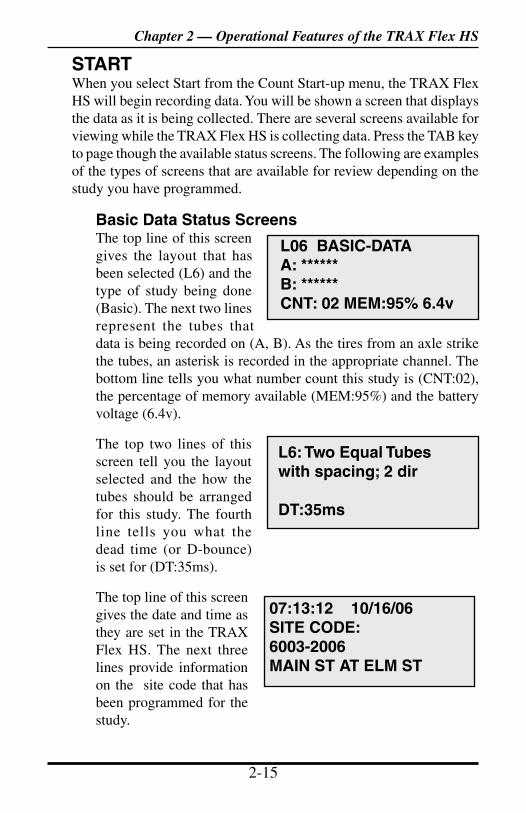
Basic Data Status ScreensThe top line of this screen gives the layout that has been selected (L6) and the type of study being done (Basic). The next two lines represent the tubes that data is being recorded on (A, B). As the tires from an axle strike the tubes, an asterisk is recorded in the appropriate channel. The bottom line tells you what number count this study is (CNT:02), the percentage of memory available (MEM:95%) and the battery voltage (6.4v).
The top two lines of this screen tell you the layout selected and the how the tubes should be arranged for this study. The fourth line tells you what the dead time (or D-bounce) is set for (DT:35ms).
The top line of this screen gives the date and time as they are set in the TRAX Flex HS. The next three lines provide information on the site code that has been programmed for the study.
L06 BASIC-DATAA: ******B: ******CNT: 02 MEM:95% 6.4v
L6: Two Equal Tubes with spacing; 2 dir
DT:35ms
07:13:12 10/16/06SITE CODE:6003-2006MAIN ST AT ELM ST
Chapter 2 — Operational Features of the TRAX Flex HS
TRAX Flex HS User’s Manual
2-16 2-17
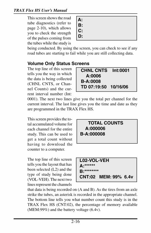
This screen shows the road tube diagnostics (refer to page 2-10), which allows you to check the strength of the pulses coming from the tubes while the study is being conducted. By using the screen, you can check to see if any road tubes are starting to fail while you are still collecting data.
Volume Only Status ScreensThe top line of this screen tells you the way in which the data is being collected (CHNL CNTS, or Chan-nel Counts) and the cur-rent interval number (Int:0001). The next two lines give you the total per channel for the current interval. The last line gives you the time and date as they are programmed in the TRAX Flex HS.
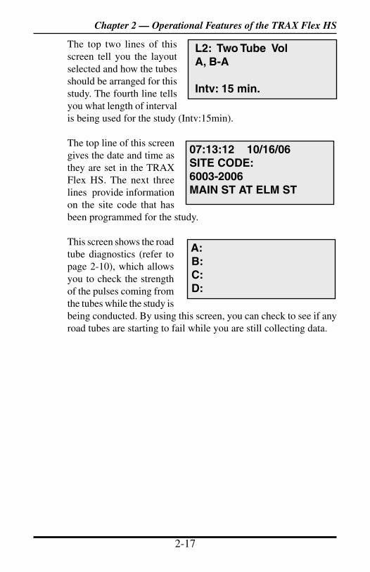
This screen provides the to-tal accumulated volume for each channel for the entire study. This can be used to get a total count without having to download the counter to a computer.
The top line of this screen tells you the layout that has been selected (L2) and the type of study being done (VOL-VEH). The next two lines represent the channels that data is being recorded on (A and B). As the tires from an axle strike the tubes, an asterisk is recorded in the appropriate channel. The bottom line tells you what number count this study is in the TRAX Flex HS (CNT:02), the percentage of memory available (MEM:99%) and the battery voltage (6.4v).
CHNL CNTS Int:0001 A:0006B-A:0008TD 07:19:50 10/16/06
TOTAL COUNTS A:000006B-A:000008
L02-VOL-VEHA:******B:********CNT:02 MEM: 99% 6.4v
A: B: C: D:
TRAX Flex HS User’s Manual
2-16 2-17
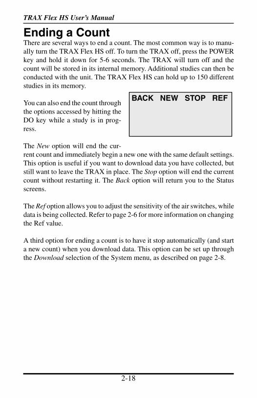
The top two lines of this screen tell you the layout selected and how the tubes should be arranged for this study. The fourth line tells you what length of interval is being used for the study (Intv:15min). The top line of this screen gives the date and time as they are set in the TRAX Flex HS. The next three lines provide information on the site code that has been programmed for the study.
This screen shows the road tube diagnostics (refer to page 2-10), which allows you to check the strength of the pulses coming from the tubes while the study is being conducted. By using this screen, you can check to see if any road tubes are starting to fail while you are still collecting data.
07:13:12 10/16/06SITE CODE:6003-2006MAIN ST AT ELM ST
L2: Two Tube VolA, B-A
Intv: 15 min.
A: B: C: D:
Chapter 2 — Operational Features of the TRAX Flex HS
TRAX Flex HS User’s Manual
2-18 2-19
BACK NEW STOP REF
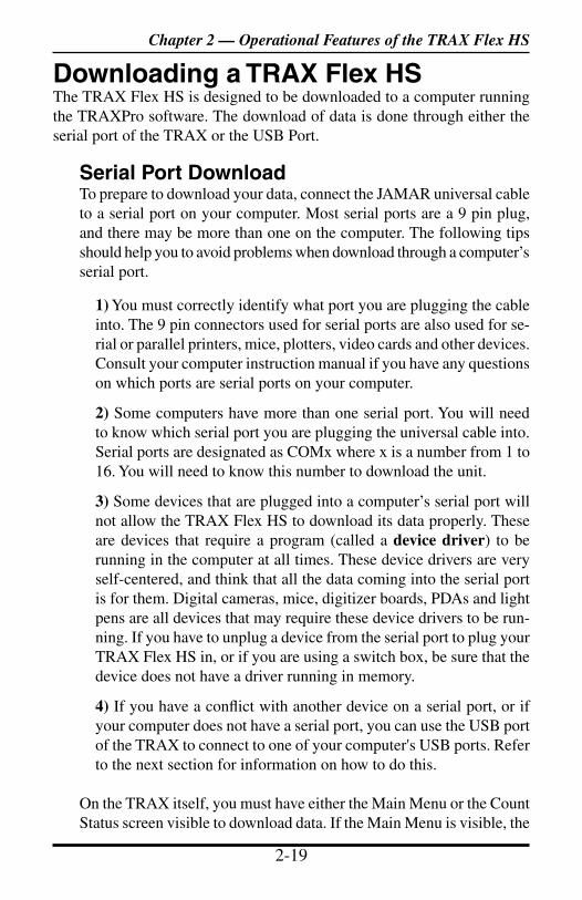
Ending a CountThere are several ways to end a count. The most common way is to manu-ally turn the TRAX Flex HS off. To turn the TRAX off, press the POWER key and hold it down for 5-6 seconds. The TRAX will turn off and the count will be stored in its internal memory. Additional studies can then be conducted with the unit. The TRAX Flex HS can hold up to 150 different studies in its memory.
You can also end the count through the options accessed by hitting the DO key while a study is in prog-ress.
The New option will end the cur-rent count and immediately begin a new one with the same default settings. This option is useful if you want to download data you have collected, but still want to leave the TRAX in place. The Stop option will end the current count without restarting it. The Back option will return you to the Status screens.
The Ref option allows you to adjust the sensitivity of the air switches, while data is being collected. Refer to page 2-6 for more information on changing the Ref value.
A third option for ending a count is to have it stop automatically (and start a new count) when you download data. This option can be set up through the Download selection of the System menu, as described on page 2-8.
TRAX Flex HS User’s Manual
2-18 2-19
Downloading a TRAX Flex HSThe TRAX Flex HS is designed to be downloaded to a computer running the TRAXPro software. The download of data is done through either the serial port of the TRAX or the USB Port.
Serial Port DownloadTo prepare to download your data, connect the JAMAR universal cable to a serial port on your computer. Most serial ports are a 9 pin plug, and there may be more than one on the computer. The following tips should help you to avoid problems when download through a computer’s serial port.
1) You must correctly identify what port you are plugging the cable into. The 9 pin connectors used for serial ports are also used for se-rial or parallel printers, mice, plotters, video cards and other devices. Consult your computer instruction manual if you have any questions on which ports are serial ports on your computer.
2) Some computers have more than one serial port. You will need to know which serial port you are plugging the universal cable into. Serial ports are designated as COMx where x is a number from 1 to 16. You will need to know this number to download the unit.
3) Some devices that are plugged into a computer’s serial port will not allow the TRAX Flex HS to download its data properly. These are devices that require a program (called a device driver) to be running in the computer at all times. These device drivers are very self-centered, and think that all the data coming into the serial port is for them. Digital cameras, mice, digitizer boards, PDAs and light pens are all devices that may require these device drivers to be run-ning. If you have to unplug a device from the serial port to plug your TRAX Flex HS in, or if you are using a switch box, be sure that the device does not have a driver running in memory.
4) If you have a conflict with another device on a serial port, or if your computer does not have a serial port, you can use the USB port of the TRAX to connect to one of your computer's USB ports. Refer to the next section for information on how to do this.
On the TRAX itself, you must have either the Main Menu or the Count Status screen visible to download data. If the Main Menu is visible, the
Chapter 2 — Operational Features of the TRAX Flex HS
TRAX Flex HS User’s Manual
2-20 2-21
download will transfer all data currently stored in memory. If the Count Status screen is visible, the download will transfer all counts stored in memory, but not the count currently being done. If you have a count in progress that you would like to download you must end the count, using one of the options discussed on page 2-18.
Once your TRAX is properly connected, start the TRAXPro software and click on the Download a TRAX counter icon and the Read TRAX Counter screen will appear.
The baud rate setting determines how fast the data will be transferred into the program. Note that the TRAX Flex HS will automatically sense whatever baud rate you select in the software. The higher the baud rate, the faster your data will be downloaded. Most computers can be set for the highest setting, 115200. Once this is set, select the com port to which you have connected the TRAX. TRAXPro will only list the com ports that are available on your computer, making the selection easier.
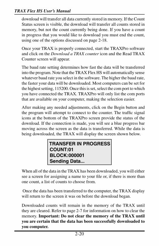
After making any needed adjustments, click on the Begin button and the program will attempt to connect to the counter. The traffic signal icons at the bottom of the TRAXPro screen provide the status of the download. If the connection is made, you will see a blue progress bar moving across the screen as the data is transferred. While the data is being downloaded, the TRAX will display the screen shown below.
When all of the data in the TRAX has been downloaded, you will either see a screen for assigning a name to your file or, if there is more than one count, a list of counts to choose from.
Once the data has been transferred to the computer, the TRAX display will return to the screen it was on before the download began.
Downloaded counts will remain in the memory of the TRAX until they are cleared. Refer to page 2-7 for information on how to clear the memory. Important: Do not clear the memory of the TRAX until you are certain that the data has been successfully downloaded to you computer.
TRANSFER IN PROGRESS COUNT:01 BLOCK:000001 Sending Data...
TRAX Flex HS User’s Manual
2-20 2-21
USB Port DownloadNote: USB download is only recommended for Windows XP or higher operating systems. We recommend using the Serial Port Download, described in the previous section, for Windows 98, ME or 2000.
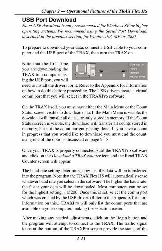
To prepare to download your data, connect a USB cable to your com-puter and the USB port of the TRAX, then turn the TRAX on.
Note that the first time you are downloading the TRAX to a computer us-ing the USB port, you will need to install the drivers for it. Refer to the Appendix for information on how to do this before proceeding. The USB drivers create a virtual comm port that you will select in the TRAXPro software.
On the TRAX itself, you must have either the Main Menu or the Count Status screen visible to download data. If the Main Menu is visible, the download will transfer all data currently stored in memory. If the Count Status screen is visible, the download will transfer all counts stored in memory, but not the count currently being done. If you have a count in progress that you would like to download you must end the count, using one of the options discussed on page 2-18.
Once your TRAX is properly connected, start the TRAXPro software and click on the Download a TRAX counter icon and the Read TRAX Counter screen will appear.
The baud rate setting determines how fast the data will be transferred into the program. Note that the TRAX Flex HS will automatically sense whatever baud rate you select in the software. The higher the baud rate, the faster your data will be downloaded. Most computers can be set for the highest setting, 115200. Once this is set, select the comm port which was created by the USB driver. (Refer to the Appendix for more information on this.) TRAXPro will only list the comm ports that are available on your computer, making the selection easier.
After making any needed adjustments, click on the Begin button and the program will attempt to connect to the TRAX. The traffic signal icons at the bottom of the TRAXPro screen provide the status of the
Chapter 2 — Operational Features of the TRAX Flex HS
TRAX Flex HS User’s Manual
2-22 3-1
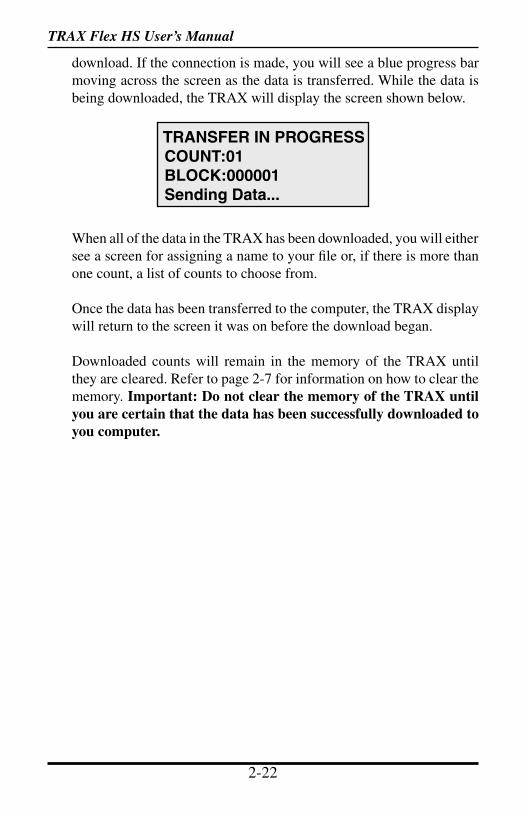
download. If the connection is made, you will see a blue progress bar moving across the screen as the data is transferred. While the data is being downloaded, the TRAX will display the screen shown below.
When all of the data in the TRAX has been downloaded, you will either see a screen for assigning a name to your file or, if there is more than one count, a list of counts to choose from.
Once the data has been transferred to the computer, the TRAX display will return to the screen it was on before the download began.
Downloaded counts will remain in the memory of the TRAX until they are cleared. Refer to page 2-7 for information on how to clear the memory. Important: Do not clear the memory of the TRAX until you are certain that the data has been successfully downloaded to you computer.
TRANSFER IN PROGRESS COUNT:01 BLOCK:000001 Sending Data...

TRAX Flex HS User’s Manual
2-22 3-1
Chapter 3 — Using the EZ Belt
Using theEZ Belt
Chapter 3
TRAX Flex HS User’s Manual
3-2 3-3
What is the EZ Belt?The EZ Belt is a revolutionary new form of road tube that eliminates the need to measure tube spacing in the field.
The belt consists of two pneumatic tubes connected together at a 4 inch spacing by a thin layer of rubber. Since the two tubes are manufactured at a set distance apart, there is no need for you to do any measuring while in the field. When connected to a TRAX Flex HS recorder, you can record accurate data for volume, speed, class and gap using the EZ Belt.
The EZ Belt comes in two sizes - a 14 foot length for one lane applications and a 26 foot length for two lane applications. The EZ Belt is installed in the lanes you want to record, then mini-tubes are connected to the end of the belt and run back to the TRAX recorder.
The EZ Belt should be replaced on a fairly consistent basis. Older belts will eventually develop splits in the tubes that can allow water to enter. When an air pulse is received, this water can be forced back into the unit’s air switch, potentially causing serious damage. Do not risk expensive repair bills by trying to squeezing a few extra studies out of old tube. One rule of thumb is to replace the EZ Belt after 30 days of use.
Installing the EZ BeltProper installation of the EZ Belt is very important for collecting accurate data with your TRAX Flex HS. The EZ Belt and the TRAX Flex HS’ air switches comprise the sensing device for the unit. As with all receivers, the sensor has to be functioning properly to record reliable information. With this in mind, examine your installations carefully and be absolutely certain that your unit is recording data as programmed.
A slideshow demonstration of the proper techniques for installing the EZ Belt can be viewed on the JAMAR web site at:
www.jamartech.comWe recommend viewing this demonstration if you are new to the process of installing the EZ Belt, or would like additional tips on installation.
TRAX Flex HS User’s Manual
3-2 3-3
Chapter 3 — Using the EZ Belt
Step 1 – Select an Installation LocationThe first step in the installation process is to select the location where the EZ Belt will be installed. The EZ Belt should be placed exactly perpen-dicular to the flow of traffic and should be installed on a straight stretch of road so that vehicles are not hitting the belt on an angle.
For the best results, do not install the EZ Belt in a location where traffic will be queueing up and stopping on the belt, or in a location where vehicle will be making a turn over the belt or otherwise striking it on an angle.
Step 2 - Select LayoutOnce you have selected your location, the next step is to decide what lay-out to use. The EZ Belt is compatible with 5 standard layouts - L3, L5, L6, L9 and L10. Which layout you select largely depends on the type of data you want to collect.
The L3 and L9 layouts allow you to record data for volume information, while the L5, L6 and L10 layouts allow you to record data for speed, class and gap in addition to volume.
The most commonly used layouts are L5 and L6. The L5 layout is de-signed for single direction traffic. The L6 layout is designed for bidirec-tional traffic over two lanes. Chapter 5, EZ Belt & Road Tube Layouts, contains more detailed information on each individual layout.
Step 3 - Prepare the Installation EquipmentOnce you have decided on your layout, you’re just about ready to install the EZ Belt. However, first be sure you have all the equipment you’ll need to do the installation quickly and efficiently. The equipment you’ll need in-cludes the EZ Belt itself, 25 foot mini road tube sections (two per belt) for connecting the EZ belt back to the TRAX, mastic tape (including several pre-cut 10 inch strips and a utility knife for cutting mastic in the field.
IMPORTANT - It is critical that the mini tubes used to connect the EZ Belt back to the TRAX Plus be IDENTICAL in length. The margin for error when using a four inch tube spacing is very small, so having the tubes be mismatched by even a small amount can have a negative effect on your results. We recommend using matched 25 foot lengths when con-nect either a one lane or two lane EZ belt back to the TRAX.
TRAX Flex HS User’s Manual
3-4 4-1
Once you have your equipment gathered, you’re ready to head out into the field.
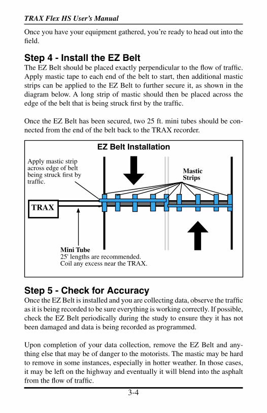
Step 4 - Install the EZ BeltThe EZ Belt should be placed exactly perpendicular to the flow of traffic. Apply mastic tape to each end of the belt to start, then additional mastic strips can be applied to the EZ Belt to further secure it, as shown in the diagram below. A long strip of mastic should then be placed across the edge of the belt that is being struck first by the traffic.
Once the EZ Belt has been secured, two 25 ft. mini tubes should be con-nected from the end of the belt back to the TRAX recorder.
Step 5 - Check for AccuracyOnce the EZ Belt is installed and you are collecting data, observe the traffic as it is being recorded to be sure everything is working correctly. If possible, check the EZ Belt periodically during the study to ensure they it has not been damaged and data is being recorded as programmed.
Upon completion of your data collection, remove the EZ Belt and any-thing else that may be of danger to the motorists. The mastic may be hard to remove in some instances, especially in hotter weather. In those cases, it may be left on the highway and eventually it will blend into the asphalt from the flow of traffic.
Mastic Strips
TRAX
EZ Belt Installation
Mini Tube25' lengths are recommended.Coil any excess near the TRAX.
Apply mastic strip across edge of belt being struck first by traffic.

TRAX Flex HS User’s Manual
3-4 4-1
Chapter 4
Road TubeInstallation
Chapter 4 — Road Tube Installation
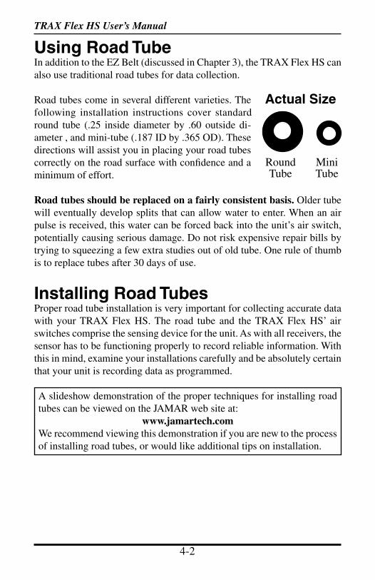
TRAX Flex HS User’s Manual
4-2 4-3
Using Road TubeIn addition to the EZ Belt (discussed in Chapter 3), the TRAX Flex HS can also use traditional road tubes for data collection.
Road tubes come in several different varieties. The following installation instructions cover standard round tube (.25 inside diameter by .60 outside di-ameter , and mini-tube (.187 ID by .365 OD). These directions will assist you in placing your road tubes correctly on the road surface with confidence and a minimum of effort.
Road tubes should be replaced on a fairly consistent basis. Older tube will eventually develop splits that can allow water to enter. When an air pulse is received, this water can be forced back into the unit’s air switch, potentially causing serious damage. Do not risk expensive repair bills by trying to squeezing a few extra studies out of old tube. One rule of thumb is to replace tubes after 30 days of use.
Installing Road TubesProper road tube installation is very important for collecting accurate data with your TRAX Flex HS. The road tube and the TRAX Flex HS’ air switches comprise the sensing device for the unit. As with all receivers, the sensor has to be functioning properly to record reliable information. With this in mind, examine your installations carefully and be absolutely certain that your unit is recording data as programmed.
A slideshow demonstration of the proper techniques for installing road tubes can be viewed on the JAMAR web site at:
www.jamartech.comWe recommend viewing this demonstration if you are new to the process of installing road tubes, or would like additional tips on installation.
Actual Size
Round Tube
MiniTube
TRAX Flex HS User’s Manual
4-2 4-3
Step 1 – Select an Installation LocationThe first step in the installation process is to select the location where the road tubes will be installed. The tubes should be placed exactly perpen-dicular to the flow of traffic and should be installed on a straight stretch of road so that vehicles are not hitting the tubes on an angle.
For the best results, do not install the tubes in a location where traffic will be queueing up and stopping on the tubes, or in a location where vehicle will be turning over the tubes or otherwise striking them on an angle.
Step 2 - Select LayoutOnce you have selected your location, the next step is to decide what lay-out to use. Which layout you select largely depends on the type of data you want to collect.
The L1, L2, L3, L4, L7, L8, L9, L13, and L14 layouts allow you to record data for volume information, while the L5, L6, L10, L11 and L12 layouts allow you to record data for speed, class and gap in addition to volume. Chapter 5, EZ Belt & Road Tube Layouts, contains more detailed informa-tion on each individual layout.
Step 3 - Prepare the Road Tube LengthsProper tube length is a crucial aspect of accurate data collection. The fol-lowing guidelines should be followed for all studies regardless of simplicity. The lengths listed for each study below have shown to provide the best results based on extensive testing.
L1, L3, L4, L5, L6, L7, L9, L10 (Long tube setups)To encompass all types of vehicles and speeds, a tube length of sixty (60) feet is recommended for standard round tube, and fifty (50) feet for mini tube. These lengths should satisfy all requirements for normal street, road, highway and interstate traffic patterns.
L2, L8, L11, L12, L13, L14 (Short tube, long tube)To ensure the pulses from the road tubes arrive at the counter in the proper order, the tube length must be the same from the edge of the road to the TRAX Flex HS. This will ensure that the pulse from the short tube arrives before the pulse from the long tube.
Chapter 4 — Road Tube Installation
TRAX Flex HS User’s Manual
4-4 4-5
Example: You are using mini tube to install an L11 layout across two lanes of traffic and each lane is twelve feet wide. In order to ensure that the distance the air pulse has to travel from the edge of the road to the counter is the same for all tubes, you should use 38 feet for the short tubes (A & C) and 50 feet for the long tubes (B & D). The short tubes will be installed over only one lane (12 feet), leaving 26 feet of tube back to the TRAX Flex HS. The long tubes will be installed over two lanes (24 feet), but since they are 50 feet long, you will still have 26 feet back to the TRAX Flex HS. For round tube, the lengths would be 48 feet for the short tubes and 60 feet for the long tubes. It is very important that the air pulses travel the same distance when two or more tubes are used to record data.
To accommodate the required length of tube, brass splices may be used to fit two tubes together. The splices are approximately three (3) inches long, hollow and do not restrict the flow of air. Do not use the splices on the roadway itself, only on the section of tube after the clamp nearest the TRAX Flex HS.
Step 4 - Prepare the Installation EquipmentOnce you have decided on your layout and prepared your tubes, you’re just about ready to begin the installation. However, first be sure you have all the equipment you’ll need to do the installation quickly and efficiently. The equipment you’ll typically need, depending on the type of road tube you are using, includes the road tubes themselves, a hammer and PK nails, mastic tape in 6 inch strips, webbing or another type of clamp, a utility knife, a tape measure, and end plugs.
Step 5 - Install the Road TubesRoad tubes should be installed exactly perpendicular to the traffic flow.
When using two or more tubes that must be set at specific distances from each other, always use a tape measure or ruler to measure from the center of each tube to determine the proper spacing. In short tube, long tube setups, the short tube should be installed to the zone line (center of the highway). Observe traffic to be sure that vehicles in the outer lane are not coming in contact with the short tube.
The following sections detail the specific installation procedures for both standard round tube and for mini tube.
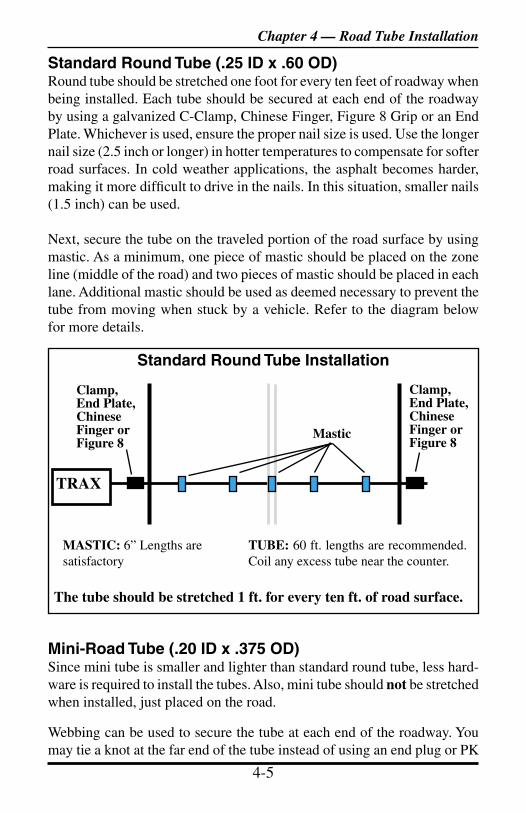
TRAX Flex HS User’s Manual
4-4 4-5
Standard Round Tube (.25 ID x .60 OD)Round tube should be stretched one foot for every ten feet of roadway when being installed. Each tube should be secured at each end of the roadway by using a galvanized C-Clamp, Chinese Finger, Figure 8 Grip or an End Plate. Whichever is used, ensure the proper nail size is used. Use the longer nail size (2.5 inch or longer) in hotter temperatures to compensate for softer road surfaces. In cold weather applications, the asphalt becomes harder, making it more difficult to drive in the nails. In this situation, smaller nails (1.5 inch) can be used.
Next, secure the tube on the traveled portion of the road surface by using mastic. As a minimum, one piece of mastic should be placed on the zone line (middle of the road) and two pieces of mastic should be placed in each lane. Additional mastic should be used as deemed necessary to prevent the tube from moving when stuck by a vehicle. Refer to the diagram below for more details.
Mini-Road Tube (.20 ID x .375 OD)Since mini tube is smaller and lighter than standard round tube, less hard-ware is required to install the tubes. Also, mini tube should not be stretched when installed, just placed on the road.
Webbing can be used to secure the tube at each end of the roadway. You may tie a knot at the far end of the tube instead of using an end plug or PK
Chapter 4 — Road Tube Installation
Standard Round Tube Installation
The tube should be stretched 1 ft. for every ten ft. of road surface.
MASTIC: 6” Lengths are satisfactory
Mastic
Clamp, End Plate,Chinese Finger or Figure 8
TRAX
Clamp, End Plate,Chinese Finger or Figure 8
TUBE: 60 ft. lengths are recommended. Coil any excess tube near the counter.
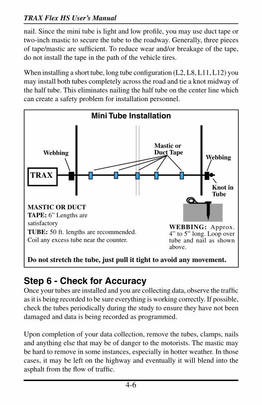
TRAX Flex HS User’s Manual
4-6 5-1
nail. Since the mini tube is light and low profile, you may use duct tape or two-inch mastic to secure the tube to the roadway. Generally, three pieces of tape/mastic are sufficient. To reduce wear and/or breakage of the tape, do not install the tape in the path of the vehicle tires.
When installing a short tube, long tube configuration (L2, L8, L11, L12) you may install both tubes completely across the road and tie a knot midway of the half tube. This eliminates nailing the half tube on the center line which can create a safety problem for installation personnel.
Step 6 - Check for AccuracyOnce your tubes are installed and you are collecting data, observe the traffic as it is being recorded to be sure everything is working correctly. If possible, check the tubes periodically during the study to ensure they have not been damaged and data is being recorded as programmed.
Upon completion of your data collection, remove the tubes, clamps, nails and anything else that may be of danger to the motorists. The mastic may be hard to remove in some instances, especially in hotter weather. In those cases, it may be left on the highway and eventually it will blend into the asphalt from the flow of traffic.
Mastic orDuct Tape
MASTIC OR DUCT TAPE: 6” Lengths are satisfactoryTUBE: 50 ft. lengths are recommended. Coil any excess tube near the counter.
Do not stretch the tube, just pull it tight to avoid any movement.
TRAX
Mini Tube Installation
Webbing
WEBBING: Approx. 4” to 5” long. Loop over tube and nail as shown above.
Webbing
Knot in Tube
TRAX Flex HS User’s Manual
4-6 5-1
Chapter 5
EZ Belt &Road Tube
Layouts
Chapter 5 — EZ Belt & Road Tube Layouts
TRAX Flex HS User’s Manual
5-2 5-3
Layouts for the TRAX Flex HSThe TRAX Flex HS is equipped with fourteen pre-programmed layouts for recording traffic data. These are designated as L1 through L14 and represent the most common types of layouts used to record traffic data.
The following are descriptions of each of the layouts, the type of data that can be collected, and the type of sensor (traditional road tube or EZ Belt) that can be used with each. Each layout is different, but there are some common principles that should be used with any layout that is chosen.
• The condition of the EZ Belt or road tubes, and the manner in which they are installed, are critical to achieving good results. Refer to Chap-ters 3 & 4 for more installation information.
• When using road tube, a tube length of sixty (60) feet is recommended for round tube, and a tube length of fifty (50) feet is recommended for mini tube.
• In all tube setups of more than one tube, the tube length from the end of the road to the TRAX must be the same for all tubes.
• In all short tube, long tube layouts, the vehicle must strike the short tube first.
• To collect class or speed data, a minimum of two feet of tube spacing is required to achieve accurate results when using traditional road tubes. If using the EZ Belt, the spacing should be set at 4 inches (0.3 ft).
• For counts done in the Volume Only mode, the TRAX Flex HS will either do a straight axle count or use the divide-by-two technique (in which every two axle hits will increment the TRAX Flex HS by one).
• Data can be collected in the Basic mode with any of the tube layouts, since basic data is essentially a collection of all the sensor activations on an individual basis. However, the minimum tube spacing requirements still apply to Basic data. If a layout says volume only, that is the only information you will be able to accurately get from it. You can collect data in the Basic mode with an L1 layout, but you will only be able to get volume data, not class, speed, etc.
The diagrams for the following layouts assume a length of twelve feet per lane of traffic and are shown for round tube and mini tube.

TRAX Flex HS User’s Manual
5-2 5-3
In this layout, channel “A” and channel “B” record independently. When in Volume mode the TRAX can do either a straight axle count or use the divide-by-two technique.
EXAMPLE: The TRAX has been programmed to use the divide-by-two technique. As a passenger car passes over the “A”, the unit records one count. As a four axle truck passes over the “A” tube the unit records two counts.
A B
TR
AX
24 ft. 26 ft. Mini36 ft. Round
24 ft.36 ft. Round
26 ft. Mini
Layout: L1Layout Type: Traditional Road TubesSensors Used: 2 Road TubesSpacing: NoneCount Formats: Basic, Volume OnlyData: Volume, GapChannels: 2 Channels, A, B
Chapter 5 — EZ Belt & Road Tube Layouts
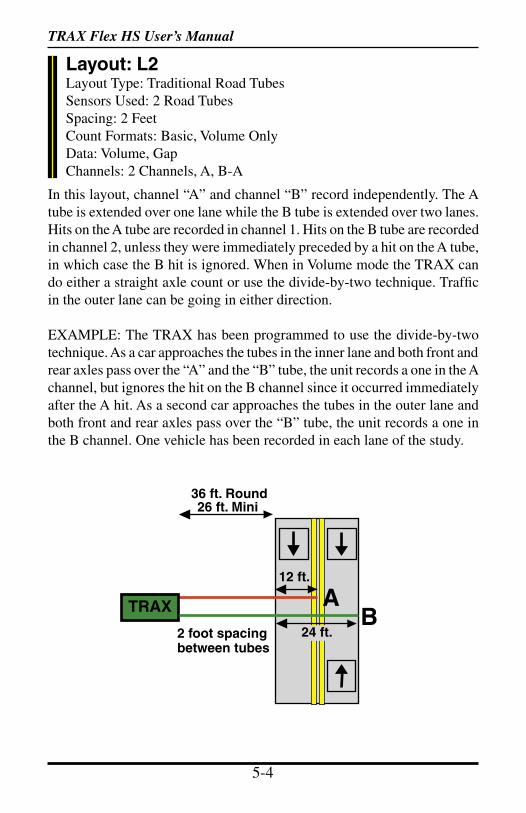
TRAX Flex HS User’s Manual
5-4 5-5
In this layout, channel “A” and channel “B” record independently. The A tube is extended over one lane while the B tube is extended over two lanes. Hits on the A tube are recorded in channel 1. Hits on the B tube are recorded in channel 2, unless they were immediately preceded by a hit on the A tube, in which case the B hit is ignored. When in Volume mode the TRAX can do either a straight axle count or use the divide-by-two technique. Traffic in the outer lane can be going in either direction.
EXAMPLE: The TRAX has been programmed to use the divide-by-two technique. As a car approaches the tubes in the inner lane and both front and rear axles pass over the “A” and the “B” tube, the unit records a one in the A channel, but ignores the hit on the B channel since it occurred immediately after the A hit. As a second car approaches the tubes in the outer lane and both front and rear axles pass over the “B” tube, the unit records a one in the B channel. One vehicle has been recorded in each lane of the study.
36 ft. Round26 ft. Mini
BTRAX A24 ft.
12 ft.
2 foot spacing between tubes
Layout: L2Layout Type: Traditional Road TubesSensors Used: 2 Road TubesSpacing: 2 FeetCount Formats: Basic, Volume OnlyData: Volume, GapChannels: 2 Channels, A, B-A
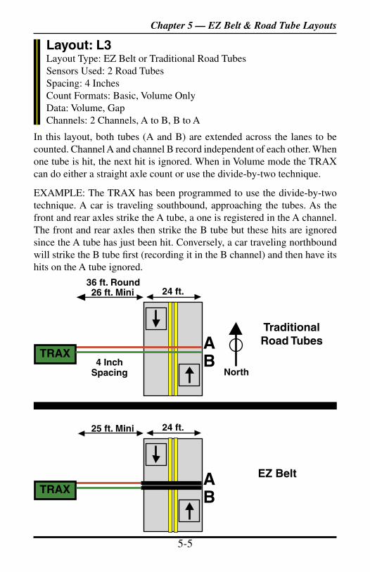
TRAX Flex HS User’s Manual
5-4 5-5
In this layout, both tubes (A and B) are extended across the lanes to be counted. Channel A and channel B record independent of each other. When one tube is hit, the next hit is ignored. When in Volume mode the TRAX can do either a straight axle count or use the divide-by-two technique.
EXAMPLE: The TRAX has been programmed to use the divide-by-two technique. A car is traveling southbound, approaching the tubes. As the front and rear axles strike the A tube, a one is registered in the A channel. The front and rear axles then strike the B tube but these hits are ignored since the A tube has just been hit. Conversely, a car traveling northbound will strike the B tube first (recording it in the B channel) and then have its hits on the A tube ignored.
BTRAXA
4 InchSpacing
24 ft.36 ft. Round26 ft. Mini
Layout: L3Layout Type: EZ Belt or Traditional Road TubesSensors Used: 2 Road TubesSpacing: 4 InchesCount Formats: Basic, Volume OnlyData: Volume, GapChannels: 2 Channels, A to B, B to A
TraditionalRoad Tubes
EZ Belt
BTRAXA
24 ft.25 ft. Mini
Chapter 5 — EZ Belt & Road Tube Layouts
North
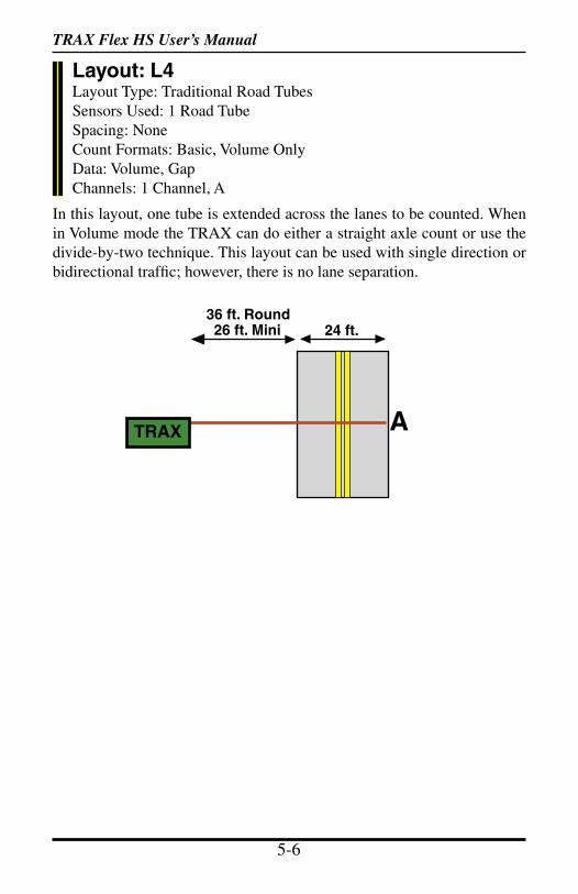
TRAX Flex HS User’s Manual
5-6 5-7
In this layout, one tube is extended across the lanes to be counted. When in Volume mode the TRAX can do either a straight axle count or use the divide-by-two technique. This layout can be used with single direction or bidirectional traffic; however, there is no lane separation.
TRAX A
24 ft.36 ft. Round26 ft. Mini
Layout: L4Layout Type: Traditional Road TubesSensors Used: 1 Road TubeSpacing: NoneCount Formats: Basic, Volume OnlyData: Volume, GapChannels: 1 Channel, A

TRAX Flex HS User’s Manual
5-6 5-7
In this layout, both tubes (A and B) are extended across the lane to be stud-ied. Channel A and channel B record dependent on each other. The tubes should be spaced two feet apart and be of equal length.
EXAMPLE: A car is traveling southbound, approaching the tubes. As the vehicle passes over both the A and B tubes, the TRAX records the class, and speed (or time-stamps) of the vehicle.
BA
12 ft.
North
TRAX
48 ft. Round38 ft. Mini
Layout: L5Layout Type: EZ Belt or Traditional Road TubesSensors Used: 2 Road TubesSpacing: 4 Inches for EZ Belt, Two Feet for Road TubesCount Formats: BasicData: Class, Speed, Gap, VolumeDirections: 1 Direction, A to B
Spacing:2 feet
BA
12 ft.
North
TRAX
25 ft. Mini
Traditional Road Tubes
EZ Belt
Chapter 5 — EZ Belt & Road Tube Layouts
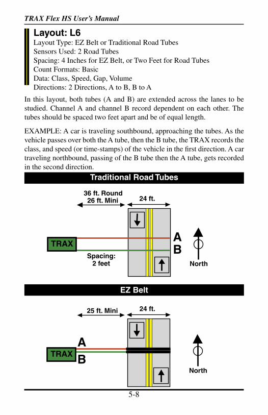
TRAX Flex HS User’s Manual
5-8 5-9
Layout: L6Layout Type: EZ Belt or Traditional Road TubesSensors Used: 2 Road TubesSpacing: 4 Inches for EZ Belt, or Two Feet for Road TubesCount Formats: BasicData: Class, Speed, Gap, VolumeDirections: 2 Directions, A to B, B to A
In this layout, both tubes (A and B) are extended across the lanes to be studied. Channel A and channel B record dependent on each other. The tubes should be spaced two feet apart and be of equal length.
EXAMPLE: A car is traveling southbound, approaching the tubes. As the vehicle passes over both the A tube, then the B tube, the TRAX records the class, and speed (or time-stamps) of the vehicle in the first direction. A car traveling northbound, passing of the B tube then the A tube, gets recorded in the second direction.
BA
24 ft.
North
TRAX
36 ft. Round26 ft. Mini
Spacing:2 feet
BA
24 ft.
North
TRAX
25 ft. Mini
Traditional Road Tubes
EZ Belt
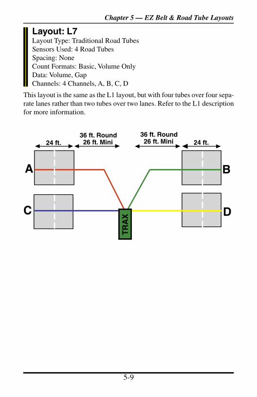
TRAX Flex HS User’s Manual
5-8 5-9
Layout: L7Layout Type: Traditional Road TubesSensors Used: 4 Road TubesSpacing: NoneCount Formats: Basic, Volume OnlyData: Volume, GapChannels: 4 Channels, A, B, C, D
This layout is the same as the L1 layout, but with four tubes over four sepa-rate lanes rather than two tubes over two lanes. Refer to the L1 description for more information.
A B
C D
TR
AX
36 ft. Round26 ft. Mini
36 ft. Round26 ft. Mini 24 ft.24 ft.
Chapter 5 — EZ Belt & Road Tube Layouts
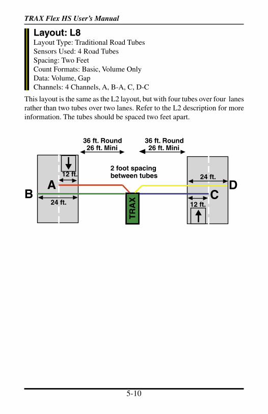
TRAX Flex HS User’s Manual
5-10 5-11
Layout: L8Layout Type: Traditional Road TubesSensors Used: 4 Road TubesSpacing: Two FeetCount Formats: Basic, Volume OnlyData: Volume, GapChannels: 4 Channels, A, B-A, C, D-C
This layout is the same as the L2 layout, but with four tubes over four lanes rather than two tubes over two lanes. Refer to the L2 description for more information. The tubes should be spaced two feet apart.
2 foot spacing between tubes
36 ft. Round26 ft. Mini
36 ft. Round26 ft. Mini
DC
12 ft.
12 ft.
24 ft.
24 ft.B
A
TR
AX
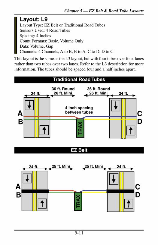
TRAX Flex HS User’s Manual
5-10 5-11
Layout: L9Layout Type: EZ Belt or Traditional Road TubesSensors Used: 4 Road TubesSpacing: 4 InchesCount Formats: Basic, Volume OnlyData: Volume, GapChannels: 4 Channels, A to B, B to A, C to D, D to C
This layout is the same as the L3 layout, but with four tubes over four lanes rather than two tubes over two lanes. Refer to the L3 description for more information. The tubes should be spaced four and a half inches apart.
DC
4 inch spacing between tubes
BA
36 ft. Round26 ft. Mini
36 ft. Round26 ft. Mini
TR
AX
24 ft. 24 ft.
Traditional Road Tubes
EZ Belt
DC
BA
25 ft. Mini 25 ft. Mini24 ft. 24 ft.
TR
AX
Chapter 5 — EZ Belt & Road Tube Layouts
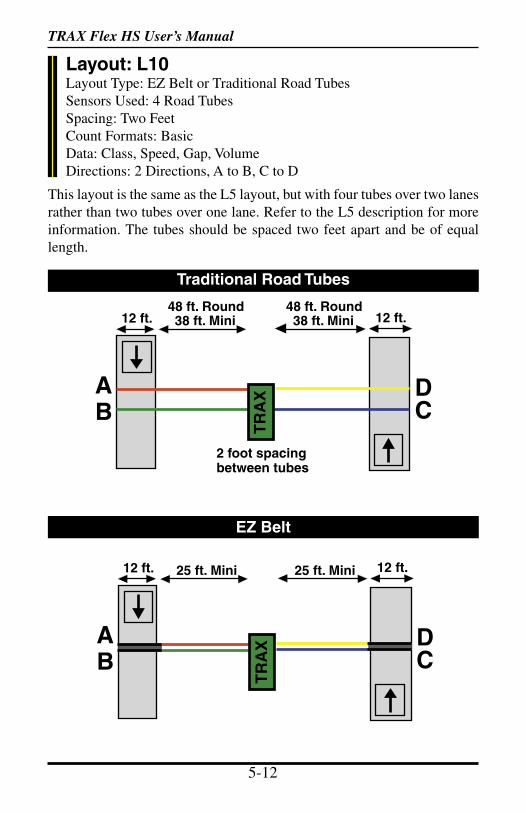
TRAX Flex HS User’s Manual
5-12 5-13
This layout is the same as the L5 layout, but with four tubes over two lanes rather than two tubes over one lane. Refer to the L5 description for more information. The tubes should be spaced two feet apart and be of equal length.
DCB
A
48 ft. Round38 ft. Mini
48 ft. Round38 ft. Mini12 ft. 12 ft.
TR
AX
Layout: L10Layout Type: EZ Belt or Traditional Road TubesSensors Used: 4 Road TubesSpacing: Two FeetCount Formats: BasicData: Class, Speed, Gap, VolumeDirections: 2 Directions, A to B, C to D
2 foot spacing between tubes
Traditional Road Tubes
EZ Belt
DCB
A
25 ft. Mini 25 ft. Mini12 ft. 12 ft.
TR
AX
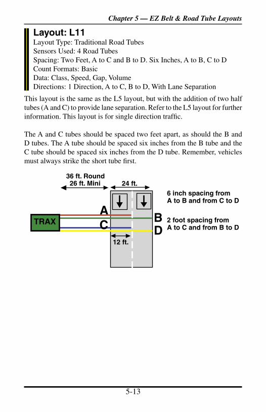
TRAX Flex HS User’s Manual
5-12 5-13
This layout is the same as the L5 layout, but with the addition of two half tubes (A and C) to provide lane separation. Refer to the L5 layout for further information. This layout is for single direction traffic.
The A and C tubes should be spaced two feet apart, as should the B and D tubes. The A tube should be spaced six inches from the B tube and the C tube should be spaced six inches from the D tube. Remember, vehicles must always strike the short tube first.
BA
24 ft.36 ft. Round26 ft. Mini
12 ft.DC
6 inch spacing fromA to B and from C to D
Layout: L11Layout Type: Traditional Road TubesSensors Used: 4 Road TubesSpacing: Two Feet, A to C and B to D. Six Inches, A to B, C to DCount Formats: BasicData: Class, Speed, Gap, VolumeDirections: 1 Direction, A to C, B to D, With Lane Separation
2 foot spacing fromA to C and from B to D
TRAX
Chapter 5 — EZ Belt & Road Tube Layouts
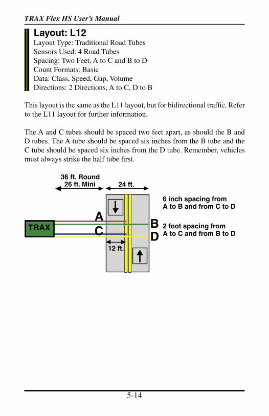
TRAX Flex HS User’s Manual
5-14 5-15
Layout: L12Layout Type: Traditional Road TubesSensors Used: 4 Road TubesSpacing: Two Feet, A to C and B to DCount Formats: BasicData: Class, Speed, Gap, VolumeDirections: 2 Directions, A to C, D to B
This layout is the same as the L11 layout, but for bidirectional traffic. Refer to the L11 layout for further information.
The A and C tubes should be spaced two feet apart, as should the B and D tubes. The A tube should be spaced six inches from the B tube and the C tube should be spaced six inches from the D tube. Remember, vehicles must always strike the half tube first.
BA
24 ft.36 ft. Round26 ft. Mini
12 ft.DC
6 inch spacing fromA to B and from C to D
2 foot spacing fromA to C and from B to D
TRAX
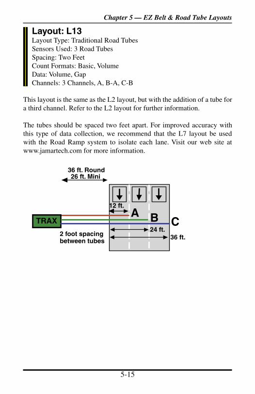
TRAX Flex HS User’s Manual
5-14 5-15
Layout: L13Layout Type: Traditional Road TubesSensors Used: 3 Road TubesSpacing: Two FeetCount Formats: Basic, VolumeData: Volume, GapChannels: 3 Channels, A, B-A, C-B
This layout is the same as the L2 layout, but with the addition of a tube for a third channel. Refer to the L2 layout for further information.
The tubes should be spaced two feet apart. For improved accuracy with this type of data collection, we recommend that the L7 layout be used with the Road Ramp system to isolate each lane. Visit our web site at www.jamartech.com for more information.
36 ft. Round26 ft. Mini
BTRAXA
12 ft.
2 foot spacing between tubes
C24 ft.
36 ft.
Chapter 5 — EZ Belt & Road Tube Layouts

TRAX Flex HS User’s Manual
5-16 6-1
Layout: L14Layout Type: Road TubesSensors Used: 4 Road TubesSpacing: Two FeetCount Formats: Basic, VolumeData: Volume, GapChannels: 4 Channels, A, B-A, C-B, D-C
This layout is the same as the L2 layout, but with the addition of two tubes for two additional channels. Refer to the L2 layout for further informa-tion.
The tubes should be spaced two feet apart. For improved accuracy with this type of data collection, we recommend that the L7 layout be used with the Road Ramp system to isolate each lane. Visit our web site at www.jamartech.com for more information.
36 ft. Round26 ft. Mini
BTRAXA
48 ft.
12 ft.
2 foot spacing between tubes
C D24 ft.
36 ft.

TRAX Flex HS User’s Manual
5-16 6-1
Chapter 6
Battery Care
Chapter 6— Battery Care
TRAX Flex HS User’s Manual
6-2 6-3
Maintaining Your BatteryThe following information regarding battery care is furnished to assist you in the use and maintenance of rechargeable batteries. Battery life is dependent on the user’s preventative maintenance procedures. Establish regular routines for all of your batteries regardless of their usage.
Charging a battery is very important for obvious reasons. Your TRAX de-pends on a fully charged battery to operate efficiently and to produce reliable and correct data. Batteries should not be allowed to sit in a discharged state for any length of time. Once the battery discharges below 5.8 volts, damage to the cells has already begun. Symptoms of a damaged battery are:
1. The battery will not charge to its full capacity of 6.4 volts or higher.2. The battery will only hold a charge for a short time under load conditions.3. The battery will discharge faster than normal during storage under no load.
With this in mind, recharge the battery to its highest potential (normally from 6.4 volts and up) once it has fallen to 6.1 or 6.0 volts. The battery can be charged through the charge port with the TRAX Battery charger (or a similar 6VDC charger with the correct plug and polarity). The battery may also be removed for charging if desired.
Solar Panel UseIf your TRAX is equipped with a solar panel, the panel can provide power to the unit when in the field and exposed to sunlight. This can extend the time between needing to recharge the battery, since the bat-tery is not being used if the unit is able to get power from the solar panel. The solar panel draws sunlight and converts it to voltage which is regulated to as high as 7.0 volts.
If your TRAX is used frequently and exposed to sunlight often, the time span between needing to manually recharge the battery will be extended. However, if your unit is used infrequently, and not exposed to sunlight, you may need to recharge the battery more often.
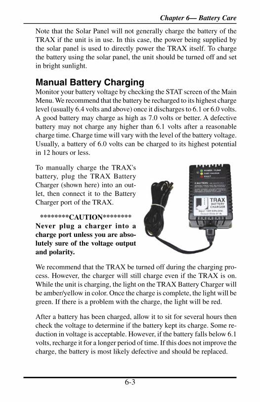
TRAX Flex HS User’s Manual
6-2 6-3
Note that the Solar Panel will not generally charge the battery of the TRAX if the unit is in use. In this case, the power being supplied by the solar panel is used to directly power the TRAX itself. To charge the battery using the solar panel, the unit should be turned off and set in bright sunlight.
Manual Battery ChargingMonitor your battery voltage by checking the STAT screen of the Main Menu. We recommend that the battery be recharged to its highest charge level (usually 6.4 volts and above) once it discharges to 6.1 or 6.0 volts. A good battery may charge as high as 7.0 volts or better. A defective battery may not charge any higher than 6.1 volts after a reasonable charge time. Charge time will vary with the level of the battery voltage. Usually, a battery of 6.0 volts can be charged to its highest potential in 12 hours or less.
To manually charge the TRAX's battery, plug the TRAX Battery Charger (shown here) into an out-let, then connect it to the Battery Charger port of the TRAX.
********CAUTION********Never plug a charger into a charge port unless you are abso-lutely sure of the voltage output and polarity.
We recommend that the TRAX be turned off during the charging pro-cess. However, the charger will still charge even if the TRAX is on. While the unit is charging, the light on the TRAX Battery Charger will be amber/yellow in color. Once the charge is complete, the light will be green. If there is a problem with the charge, the light will be red.
After a battery has been charged, allow it to sit for several hours then check the voltage to determine if the battery kept its charge. Some re-duction in voltage is acceptable. However, if the battery falls below 6.1 volts, recharge it for a longer period of time. If this does not improve the charge, the battery is most likely defective and should be replaced.
Chapter 6— Battery Care
TRAX Flex HS User’s Manual
6-4 6-5
Monitor your battery voltages frequently, charging when necessary, and you will extend the life of your battery.
Additional Notes• Do not expose the battery to moisture or rain.• Do not drop, hit or abuse the battery — it may break and expose the contents, which are highly corrosive.• Do not short circuit battery terminals. Some batteries are protected with self-resetting fuses, but short circuits may still cause severe dam-age to the battery.• It is normal for a battery to become warm to the touch during charg-ing.• It is normal for a battery to “self discharge” during prolonged stor-age. Always fully charge a battery prior to storage. While in storage, periodically check the batteries with a voltmeter to ensure they have not discharged below a level that may cause permanent damage.• Always store in a cool, dry location.• Keep batteries away from fire and do not incinerate — they may explode.• Under no circumstances should you attempt to open the battery case.• Always observe polarity when connecting your battery to any electronic/electrical device. If your device is not protected for im-proper battery hookup, you may cause severe damage to the electronic circuitry. The positive terminal may be indicated by a plus (+) sign or red mark. The negative terminal may be indicated by a minus (-) sign or black mark.• The effectiveness of the solar panel can be reduced if it is dirty or scratched up. For best results, try to keep the panel clean.
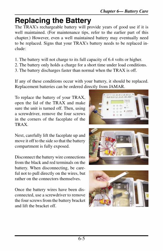
TRAX Flex HS User’s Manual
6-4 6-5
Replacing the BatteryThe TRAX's rechargeable battery will provide years of good use if it is well maintained. (For maintenance tips, refer to the earlier part of this chapter.) However, even a well maintained battery may eventually need to be replaced. Signs that your TRAX's battery needs to be replaced in-clude:
1. The battery will not charge to its full capacity of 6.4 volts or higher.2. The battery only holds a charge for a short time under load conditions.3. The battery discharges faster than normal when the TRAX is off.
If any of these conditions occur with your battery, it should be replaced. Replacement batteries can be ordered directly from JAMAR.
To replace the battery of your TRAX, open the lid of the TRAX and make sure the unit is turned off. Then, using a screwdriver, remove the four screws in the corners of the faceplate of the TRAX.
Next, carefully lift the faceplate up and move it off to the side so that the battery compartment is fully exposed.
Disconnect the battery wire connections from the black and red terminals on the battery. When disconnecting, be care-ful not to pull directly on the wires, but rather on the connectors themselves.
Once the battery wires have been dis-connected, use a screwdriver to remove the four screws from the battery bracket and lift the bracket off.
Chapter 6— Battery Care
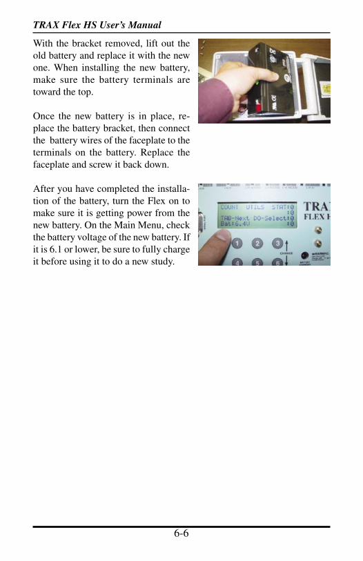
TRAX Flex HS User’s Manual
6-6 7-1
With the bracket removed, lift out the old battery and replace it with the new one. When installing the new battery, make sure the battery terminals are toward the top.
Once the new battery is in place, re-place the battery bracket, then connect the battery wires of the faceplate to the terminals on the battery. Replace the faceplate and screw it back down.
After you have completed the installa-tion of the battery, turn the Flex on to make sure it is getting power from the new battery. On the Main Menu, check the battery voltage of the new battery. If it is 6.1 or lower, be sure to fully charge it before using it to do a new study.

TRAX Flex HS User’s Manual
6-6 7-1
Chapter 7
Troubleshooting
Chapter 7 — Troubleshooting
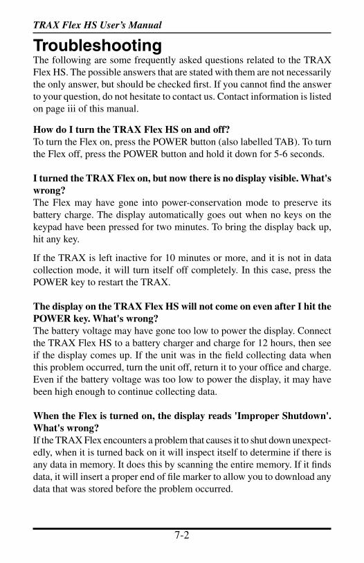
TRAX Flex HS User’s Manual
7-2 7-3
TroubleshootingThe following are some frequently asked questions related to the TRAX Flex HS. The possible answers that are stated with them are not necessarily the only answer, but should be checked first. If you cannot find the answer to your question, do not hesitate to contact us. Contact information is listed on page iii of this manual.
How do I turn the TRAX Flex HS on and off?To turn the Flex on, press the POWER button (also labelled TAB). To turn the Flex off, press the POWER button and hold it down for 5-6 seconds.
I turned the TRAX Flex on, but now there is no display visible. What's wrong?The Flex may have gone into power-conservation mode to preserve its battery charge. The display automatically goes out when no keys on the keypad have been pressed for two minutes. To bring the display back up, hit any key.
If the TRAX is left inactive for 10 minutes or more, and it is not in data collection mode, it will turn itself off completely. In this case, press the POWER key to restart the TRAX.
The display on the TRAX Flex HS will not come on even after I hit the POWER key. What's wrong?The battery voltage may have gone too low to power the display. Connect the TRAX Flex HS to a battery charger and charge for 12 hours, then see if the display comes up. If the unit was in the field collecting data when this problem occurred, turn the unit off, return it to your office and charge. Even if the battery voltage was too low to power the display, it may have been high enough to continue collecting data.
When the Flex is turned on, the display reads 'Improper Shutdown'. What's wrong?If the TRAX Flex encounters a problem that causes it to shut down unexpect-edly, when it is turned back on it will inspect itself to determine if there is any data in memory. It does this by scanning the entire memory. If it finds data, it will insert a proper end of file marker to allow you to download any data that was stored before the problem occurred.
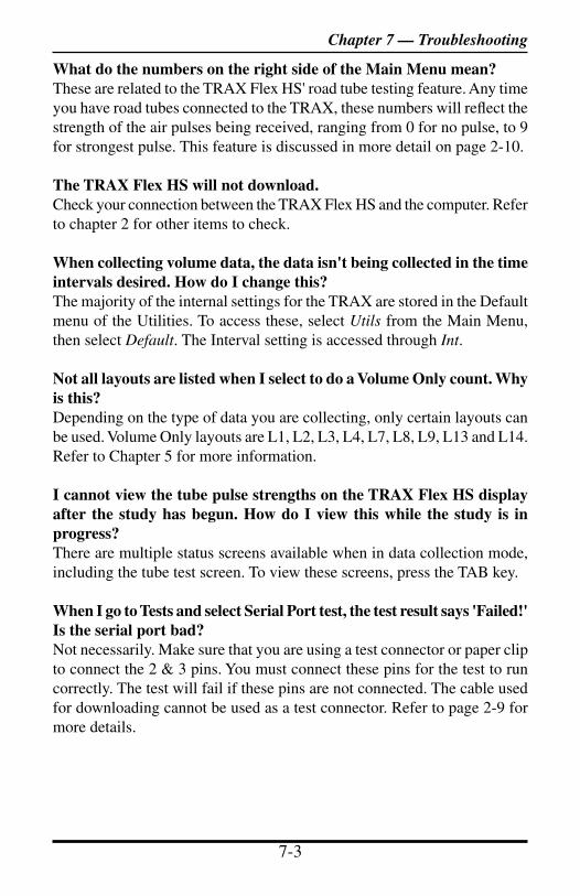
TRAX Flex HS User’s Manual
7-2 7-3
What do the numbers on the right side of the Main Menu mean?These are related to the TRAX Flex HS' road tube testing feature. Any time you have road tubes connected to the TRAX, these numbers will reflect the strength of the air pulses being received, ranging from 0 for no pulse, to 9 for strongest pulse. This feature is discussed in more detail on page 2-10.
The TRAX Flex HS will not download.Check your connection between the TRAX Flex HS and the computer. Refer to chapter 2 for other items to check.
When collecting volume data, the data isn't being collected in the time intervals desired. How do I change this?The majority of the internal settings for the TRAX are stored in the Default menu of the Utilities. To access these, select Utils from the Main Menu, then select Default. The Interval setting is accessed through Int.
Not all layouts are listed when I select to do a Volume Only count. Why is this?Depending on the type of data you are collecting, only certain layouts can be used. Volume Only layouts are L1, L2, L3, L4, L7, L8, L9, L13 and L14. Refer to Chapter 5 for more information.
I cannot view the tube pulse strengths on the TRAX Flex HS display after the study has begun. How do I view this while the study is in progress?There are multiple status screens available when in data collection mode, including the tube test screen. To view these screens, press the TAB key.
When I go to Tests and select Serial Port test, the test result says 'Failed!' Is the serial port bad?Not necessarily. Make sure that you are using a test connector or paper clip to connect the 2 & 3 pins. You must connect these pins for the test to run correctly. The test will fail if these pins are not connected. The cable used for downloading cannot be used as a test connector. Refer to page 2-9 for more details.
Chapter 7 — Troubleshooting

TRAX Flex HS User’s Manual
7-4 A-1
The data I'm getting is not accurate. What went wrong?In most cases, issues with bad data are related to the road tubes and how they were installed. Check the tube layout used in the field and the condition of the tubes themselves. Make sure the tubes were set with the proper length, spacing and perpendicular to the flow of traffic. One simple condition check of a tube that is laid out in the field is to go to use the Tube Test diagnostic. Refer to page 2-10 for more information on this.
Additional support information can also be found on our web site at www.jamartech.com. If you are unable to find a solution to your problem, contact us using the information located on the first page iii of this manual.

TRAX Flex HS User’s Manual
7-4 A-1
Appendix
Appendix
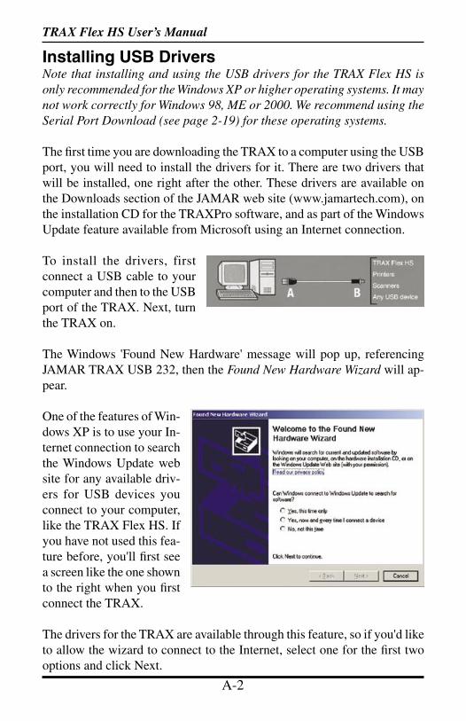
TRAX Flex HS User’s Manual
A-2 A-3
Installing USB DriversNote that installing and using the USB drivers for the TRAX Flex HS is only recommended for the Windows XP or higher operating systems. It may not work correctly for Windows 98, ME or 2000. We recommend using the Serial Port Download (see page 2-19) for these operating systems.
The first time you are downloading the TRAX to a computer using the USB port, you will need to install the drivers for it. There are two drivers that will be installed, one right after the other. These drivers are available on the Downloads section of the JAMAR web site (www.jamartech.com), on the installation CD for the TRAXPro software, and as part of the Windows Update feature available from Microsoft using an Internet connection.
To install the drivers, first connect a USB cable to your computer and then to the USB port of the TRAX. Next, turn the TRAX on.
The Windows 'Found New Hardware' message will pop up, referencing JAMAR TRAX USB 232, then the Found New Hardware Wizard will ap-pear.
One of the features of Win-dows XP is to use your In-ternet connection to search the Windows Update web site for any available driv-ers for USB devices you connect to your computer, like the TRAX Flex HS. If you have not used this fea-ture before, you'll first see a screen like the one shown to the right when you first connect the TRAX.
The drivers for the TRAX are available through this feature, so if you'd like to allow the wizard to connect to the Internet, select one for the first two options and click Next.
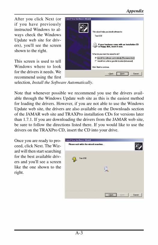
TRAX Flex HS User’s Manual
A-2 A-3
After you click Next (or if you have previously instructed Windows to al-ways check the Windows Update web site for driv-ers), you'll see the screen shown to the right.
This screen is used to tell Windows where to look for the drivers it needs. We recommend using the first selection, Install the Software Automatically.
Note that whenever possible we recommend you use the drivers avail-able through the Windows Update web site as this is the easiest method for loading the drivers. However, if you are not able to use the Windows Update web site, the drivers are also available on the Downloads section of the JAMAR web site and TRAXPro installation CDs for versions later than 1.7.1. If you are downloading the drivers from the JAMAR web site, be sure to follow the directions listed there. If you would like to use the drivers on the TRAXPro CD, insert the CD into your drive.
Once you are ready to pro-ceed, click Next. The Wiz-ard will then start searching for the best available driv-ers and you'll see a screen like the one shown to the right.
Appendix
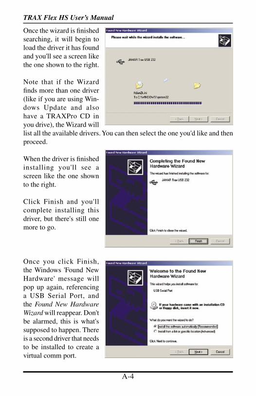
TRAX Flex HS User’s Manual
A-4 A-5
Once the wizard is finished searching, it will begin to load the driver it has found and you'll see a screen like the one shown to the right.
Note that if the Wizard finds more than one driver (like if you are using Win-dows Update and also have a TRAXPro CD in you drive), the Wizard will list all the available drivers. You can then select the one you'd like and then proceed.
When the driver is finished installing you'll see a screen like the one shown to the right.
Click Finish and you'll complete installing this driver, but there's still one more to go.
Once you click Finish, the Windows 'Found New Hardware' message will pop up again, referencing a USB Serial Port, and the Found New Hardware Wizard will reappear. Don't be alarmed, this is what's supposed to happen. There is a second driver that needs to be installed to create a virtual comm port.

TRAX Flex HS User’s Manual
A-4 A-5
To install this second driver, follow the same steps as the first.
Once the second driver is installed, you may see a message like the one below, prompting you to restart your computer.
Restart your computer to complete the process of installing the drivers.
The process of installing the USB drivers has created a virtual comm port on your computer and assigned this port a number from 1 to 16. You will need to select this comm port number in TRAXPro when you go to download your TRAX. TRAXPro makes this easier to do by only listing the comm ports that are available in the download screen. However, if you want to check to see what port number the virtual comm port has been assigned, you can do so through the computer's Device Manager list.
Appendix
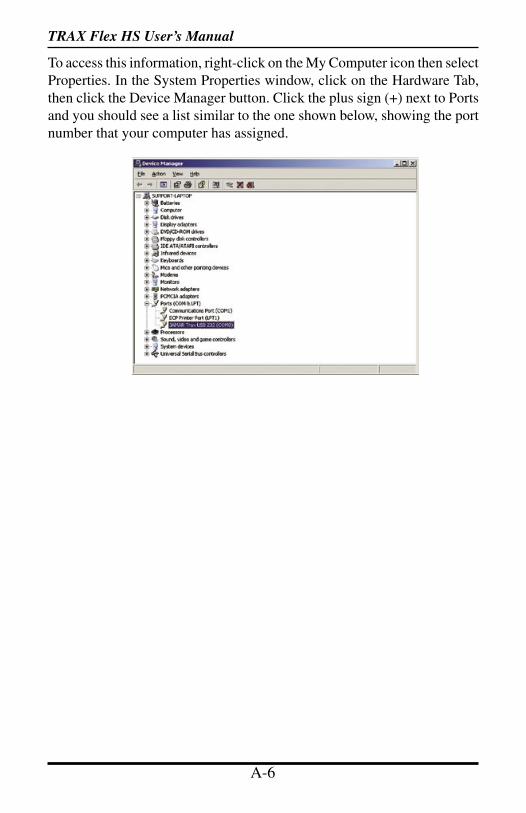
TRAX Flex HS User’s Manual
A-6 A-7
To access this information, right-click on the My Computer icon then select Properties. In the System Properties window, click on the Hardware Tab, then click the Device Manager button. Click the plus sign (+) next to Ports and you should see a list similar to the one shown below, showing the port number that your computer has assigned.
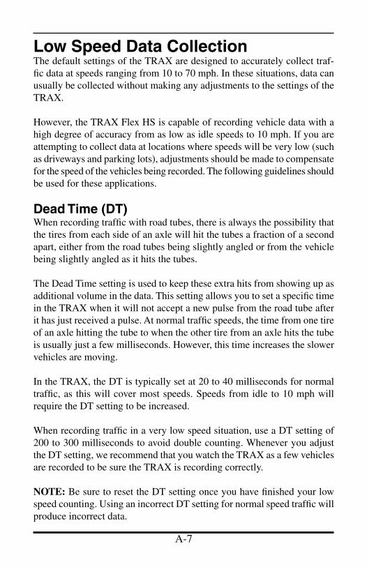
TRAX Flex HS User’s Manual
A-6 A-7
Low Speed Data CollectionThe default settings of the TRAX are designed to accurately collect traf-fic data at speeds ranging from 10 to 70 mph. In these situations, data can usually be collected without making any adjustments to the settings of the TRAX.
However, the TRAX Flex HS is capable of recording vehicle data with a high degree of accuracy from as low as idle speeds to 10 mph. If you are attempting to collect data at locations where speeds will be very low (such as driveways and parking lots), adjustments should be made to compensate for the speed of the vehicles being recorded. The following guidelines should be used for these applications.
Dead Time (DT)When recording traffic with road tubes, there is always the possibility that the tires from each side of an axle will hit the tubes a fraction of a second apart, either from the road tubes being slightly angled or from the vehicle being slightly angled as it hits the tubes.
The Dead Time setting is used to keep these extra hits from showing up as additional volume in the data. This setting allows you to set a specific time in the TRAX when it will not accept a new pulse from the road tube after it has just received a pulse. At normal traffic speeds, the time from one tire of an axle hitting the tube to when the other tire from an axle hits the tube is usually just a few milliseconds. However, this time increases the slower vehicles are moving.
In the TRAX, the DT is typically set at 20 to 40 milliseconds for normal traffic, as this will cover most speeds. Speeds from idle to 10 mph will require the DT setting to be increased.
When recording traffic in a very low speed situation, use a DT setting of 200 to 300 milliseconds to avoid double counting. Whenever you adjust the DT setting, we recommend that you watch the TRAX as a few vehicles are recorded to be sure the TRAX is recording correctly.
NOTE: Be sure to reset the DT setting once you have finished your low speed counting. Using an incorrect DT setting for normal speed traffic will produce incorrect data.
TRAX Flex HS User’s Manual
A-8 A-9
Tube LengthThe total length of road tubes used in low speed applications should not exceed forty (40) feet. Shorter lengths may be used provided all traffic is travelling at low speeds.
Tube PlacementThe TRAX will record a count even if the front and rear tires on only one side of the vehicle passes over the tube. As a result, you may choose to extend the road tube only as far as is necessary to be hit by one side of the vehicle.
The above rules may be varied slightly since each tube installation for low speed traffic counting is unique. The tube length and DT may be adjusted to fit your specific parameters. Once you have decided on your settings, monitor incoming data to ensure accuracy.
With low speed data collection, we recommend that data be collected in the Basic mode. This allows you to make further adjustments in the TRAXPro software once your data has been downloaded.

TRAX Flex HS User’s Manual
A-8 A-9
FHWA Type F Vehicle Classification SchemeClass 1 - Motorcycles. This class includes all two- or three-wheeled motorized vehicles. These vehicles typically have a saddle-type of seat and are steered by handlebars rather than a steering wheel. This includes motorcycles, motor scooters, mopeds, motor-powered bicycles and three-wheel motorcycles.
Class 2 - Passenger cars. This class includes all sedans, coupes and station wagons manufactured primarily for the purpose of carrying passengers, including those pulling recreational or other light trailers.
Class 3 - Pickups, Vans and other 2-axle, 4-tire single unit vehicles. This class includes all two-axle, four tire ve-hicles other than passenger cars, which includes pickups, vans, campers, small motor homes, ambulances, minibuses and carryalls. These types of vehicles which are pulling recreational or other light trailers are included.
Class 4 - Buses. This class includes all vehicles manu-factured as traditional passenger-carrying buses with two axles and six tires or three or more axles. This includes only traditional buses, including school and transit buses, functioning as passenger-carrying vehicles. All two-axle, four tire minibuses should be classified as Class 3. Mod-ified buses should be considered to be trucks and classified appropriately.
Class 5 - Two-Axle, Six-Tire Single Unit Trucks. This class includes all vehicles on a single frame which have two axles and dual rear tires. This includes trucks, camp-ing and recreation vehicles, motor homes, etc.
Class 6 - Three-Axle Single Unit Trucks. This class includes all vehicles on a single frame which have three axles. This includes trucks, camping and recreation ve-hicles, motor homes, etc.
Class 7 - Four or More Axle Single Unit Trucks. This class includes all vehicles on a single frame with four or more axles.
Appendix
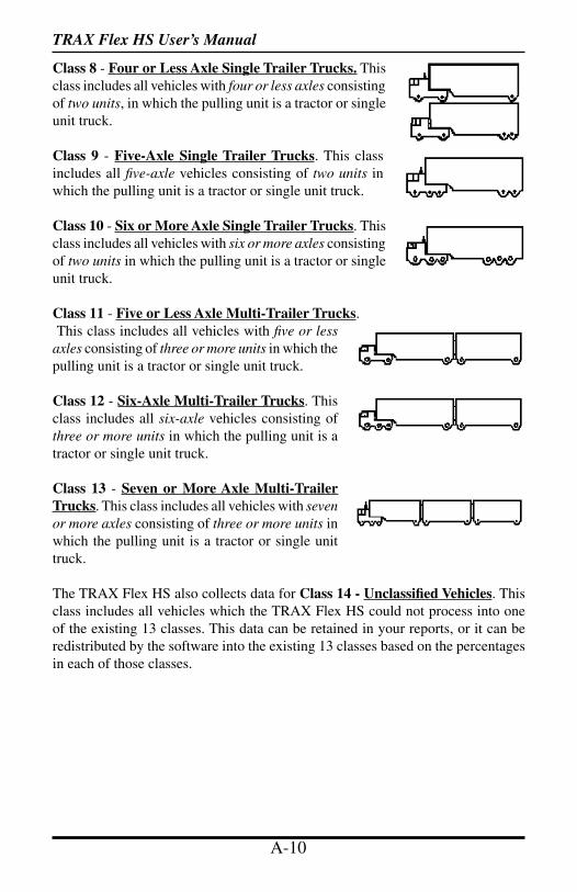
TRAX Flex HS User’s Manual
A-10 A-11
Class 8 - Four or Less Axle Single Trailer Trucks. This class includes all vehicles with four or less axles consisting of two units, in which the pulling unit is a tractor or single unit truck.
Class 9 - Five-Axle Single Trailer Trucks. This class includes all five-axle vehicles consisting of two units in which the pulling unit is a tractor or single unit truck.
Class 10 - Six or More Axle Single Trailer Trucks. This class includes all vehicles with six or more axles consisting of two units in which the pulling unit is a tractor or single unit truck.
Class 11 - Five or Less Axle Multi-Trailer Trucks. This class includes all vehicles with five or less axles consisting of three or more units in which the pulling unit is a tractor or single unit truck.
Class 12 - Six-Axle Multi-Trailer Trucks. This class includes all six-axle vehicles consisting of three or more units in which the pulling unit is a tractor or single unit truck.
Class 13 - Seven or More Axle Multi-Trailer Trucks. This class includes all vehicles with seven or more axles consisting of three or more units in which the pulling unit is a tractor or single unit truck.
The TRAX Flex HS also collects data for Class 14 - Unclassified Vehicles. This class includes all vehicles which the TRAX Flex HS could not process into one of the existing 13 classes. This data can be retained in your reports, or it can be redistributed by the software into the existing 13 classes based on the percentages in each of those classes.
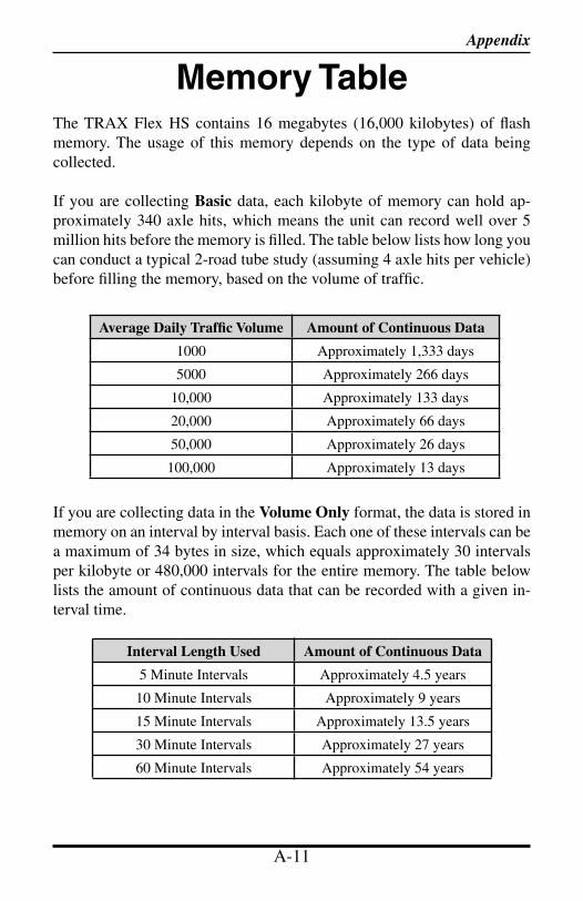
TRAX Flex HS User’s Manual
A-10 A-11
Appendix
Memory TableThe TRAX Flex HS contains 16 megabytes (16,000 kilobytes) of flash memory. The usage of this memory depends on the type of data being collected.
If you are collecting Basic data, each kilobyte of memory can hold ap-proximately 340 axle hits, which means the unit can record well over 5 million hits before the memory is filled. The table below lists how long you can conduct a typical 2-road tube study (assuming 4 axle hits per vehicle) before filling the memory, based on the volume of traffic.
If you are collecting data in the Volume Only format, the data is stored in memory on an interval by interval basis. Each one of these intervals can be a maximum of 34 bytes in size, which equals approximately 30 intervals per kilobyte or 480,000 intervals for the entire memory. The table below lists the amount of continuous data that can be recorded with a given in-terval time.
Interval Length Used Amount of Continuous Data
5 Minute Intervals Approximately 4.5 years
10 Minute Intervals Approximately 9 years
15 Minute Intervals Approximately 13.5 years
30 Minute Intervals Approximately 27 years
60 Minute Intervals Approximately 54 years
Average Daily Traffic Volume Amount of Continuous Data
1000 Approximately 1,333 days
5000 Approximately 266 days
10,000 Approximately 133 days
20,000 Approximately 66 days
50,000 Approximately 26 days
100,000 Approximately 13 days
TRAX Flex HS User’s Manual
A-12
SpecificationsSize: 11” x 7” x 4.5”Weight: Approximately 8 poundsPower: Rechargeable lead gel battery with optional solar panelInterface: RS-232 serial comm port, 9 pin DBS socket or USB 'B' portDownload Speed: Up to 115200 bpsMemory: 16 MB Internal MemoryClock: Always active real-time clockData Collection Formats: Volume, Time-stamped raw dataInputs: Four road tubesTemperature Range: Minus 40F (-40C) to 165F (74C)Date Format: USA (MM/DD/YY) or World (DD/MM/YY)Recording Intervals: 5, 10, 15, 30, 60 minutes for Volume Only formatUnits: English (feet) or Metric (meters)Display: Wide Temperature, 4-line by 20-character LCD displayOutput: Binary file capable of being read by JAMAR software
We are pleased that you have chosen the JAMAR TRAX Flex HS for your traffic data collection needs. We have strived to develop a unit that is easy to use and has the options that our customers require. The TRAX Flex HS has undergone extensive testing to verify the accuracy of its operations, and each unit is tested before it leaves our facility. However, just like other complex electronic devices, problems can occur. We always suggested that users verify the continuing accuracy of any device they use. Verification against manual counts, or with a JAMAR Traffic Counter Tester, should be performed on an annual basis as required by the FHWA to assure proper operations and results.
Should you detect any problems with any of our products, please notify JAMAR Technologies immediately and discontinue use of the unit until we have verified its operation.