
Trapped Key I n t e r l o c k s for the user Interlock systems with locking devices of this nature...
28
Trapped Key I n t e r l o c k s © HST 11_07 EN ISS Safety Limited Devonshire House, 582 Honeypot Lane, Stanmore, Middlesex HA7 1JS +44 (0) 208 732 5505 e-mail [email protected] www.iss-safety.co.uk
Transcript of Trapped Key I n t e r l o c k s for the user Interlock systems with locking devices of this nature...

Trapped Key I n t e r l o c k s
©H
ST
11_0
7 E
N
ISS Safety LimitedDevonshire House, 582 Honeypot Lane, Stanmore, Middlesex HA7 1JS+44 (0) 208 732 5505 e-mail [email protected] www.iss-safety.co.uk

C O N T E N T S B R I E F D E S C R I P T I O N
Hazardous machines and systems are frequently equipped with safety elements (safety doors) with a locking mechanism to protect the operator. Their function is:
a) to prevent hazardous machine functions if the safety door is not closed and locked,
b) to keep the safety door closed and locked until the risk of injury has passed.
Safety of machinery
2
Brief description
User-friendliness
Advantages
Areas of application
Keys
Rotary switch HST-S
Rotary switch with solenoid HST-M
2
3
4
5
6
7 - 8
9 - 10
Bolt interlock HST-B13 - 14
Door interlock HST-TS
Door interlock HST-TZ
Key exchange unit HST-X
15 - 16
17 - 18
19 - 20
Key exchange unit HST-W 21
Examples 25 - 27
Enquiry form 28
Switchgear LockHST-LS 22-23
Accessories 24
Rotary switch with Time delay HST- TD HST-BEMF
11 - 12
ISS Safety LimitedDevonshire House, 582 Honeypot Lane, Stanmore, Middlesex HA7 1JS+44 (0) 208 732 5505 e-mail [email protected] www.iss-safety.co.uk

Advantages for the userInterlock systems with locking devices of this nature include key-operated mechanical interlocks, also known as key transfer systems. They are based on the easily understood premise that a key cannot be in two places at the same time. It can, for instance, be inserted in a switch OR be used for opening a door interlock.
Another important safety characteristic is that a keycan only be withdrawn in a safe condition where no hazards exist (a switch isturned off, a door interlock is closed andlocked).
The great advantage of the system is the fact that a particular sequence of measures can be implementedwhen designing the system. It is not possible to deviate from this sequence, so a high degree of safety is achieved.
This means that virtually any hazard can be eliminated.The systems consists of central electrical elements (e.g. in the control panel) and mechanical units on the safety doors. The devices are very often used in areas where electrical components are not suitable or expensive to install, due to space considerations, other environmental conditions or explosion hazards.
Devices can be supplied with individual codes (up to 5 engraved digits). This enables the achievement of a higherdegree of safety and better protection against tampering.
B E N E F I T S F O R U S E R
3ISS Safety Limited
Devonshire House, 582 Honeypot Lane, Stanmore, Middlesex HA7 1JS+44 (0) 208 732 5505 e-mail [email protected] www.iss-safety.co.uk

Advantages
- High degree of safety
- Stainless steal standard
- Dust-cap standard
- Only pre-determined secure
safety sequences are possible
- No spare actuator “in the pocket”
- No cables to individual safety doors (cost savings,
fault prevention)
- Easy retro-fitting
- Door interlocks have a locking feature
- particularly suited when there are differentenergy types on the machine(electric, pneumatic, ...)
- In areas where people can be trapped: personal safety key
- Simple option for realising safety conditionsfor setup
- Time delay due to key transfer between the switch and interlock
- running-down processes come to a standstill (extend with additional unit if necessary)
- BG certified
Advantages of mechanical door interlocks:
A D V A N T A G E S
4ISS Safety Limited
Devonshire House, 582 Honeypot Lane, Stanmore, Middlesex HA7 1JS+44 (0) 208 732 5505 e-mail [email protected] www.iss-safety.co.uk

Varied applications or personnel safety
Automotive industry
Robots
Machine tools
Automation
Packaging machines
Food
Textiles
Breweries
Building industry
Chemical industry
Pharmaceutical industry
Plastics
Oil / Gas
Steel
Mining
Power generation / distribution
Environmental protection
Power stations
A R E A S O F A P P L I C A T I O N
5ISS Safety Limited
Devonshire House, 582 Honeypot Lane, Stanmore, Middlesex HA7 1JS+44 (0) 208 732 5505 e-mail [email protected] www.iss-safety.co.uk

6
Keys are coded so that they only fit the lock for which they areintended, thus ensuring a high degree of safety.
The user selects an engraving for the key that is of relevance to him or her (max. 5 digits). This appears on the key, the respectivelock and its dust-cap.
The manufacturer assigns an internal code to the desired engraving, and this code data is stored to enable delivery of the correct devices in the event of subsequent orders at a later stage.
Features / Technical data:Key is manufactured completely of stainless steelAlphanumeric engraving of up to 5 different digitsHigh quantity of different codes
K E Y HST-K1
ORDERING CODE
HST-K1-xxxxx key with engraving xxxxx
ISS Safety LimitedDevonshire House, 582 Honeypot Lane, Stanmore, Middlesex HA7 1JS+44 (0) 208 732 5505 e-mail [email protected] www.iss-safety.co.uk

7
R O T A R Y S W I T C H HST-S
Ordering code
HST-S _ -
The HST-S switch is used for isolating the machine. After the voltage has been switched off, the previously trapped key can be withdrawn and used for the next step (e.g. opening a safety door).
The unit is available as a cast aluminium housing or panel-mounted version.
Versions with multiple locks are also available (sheet-steel housing version with up to 2 locks, up to 5 for the panel-mounted version).Moreover, versions in explosion-proof housings conforming to ATEX are also available (zones 21 and 22 and 1 and 2, documents available on request).
It is important to give consideration to the running-down duration of the drive when utilising this switch type to ensure that the hazard zone can only be reached when the drive is stationary.
Features / Technical data:Standard reference: DIN EN 60947-1Ambient temperature: 0 - 55°CMech. service life: 1 million actuationsSwitch approval: UL, CSA, equivalent to requirements of
VDE 0660 Part 107Material of lock / actuator: stainless steel
Degree of protection: housing version: IP 54Degree of protection: panel version: IP 2X
Rated continuous current (lu/lth): 20ARated operating current (AC-15) 5A (240V)Rated insulation voltage (Ui): 690 V(wich can vary in different approbations)Rated impulse withstand voltage resistance level (Uimp): 6kVShort-circuit resistance (Si.): max. 25 A (gl)Connection cable cross section: 2 x 0.5 - 2 x 2.5 mm2
Please note: This switch is a control switch, NOT a load-break switch.Version with a load-break switch on request.
Contact versions:11 = 1Ö+1S 20 = 2Ö 22 = 2Ö + 2S 40 = 4Ö
Number of locks:(housing version up to 2, panel version up to 5)
Version:U = panel version A = housing version
HST-SU1Panel, one lock
HST-SA1Housing, one lock
HST-SU2Panel, two locks
ISS Safety LimitedDevonshire House, 582 Honeypot Lane, Stanmore, Middlesex HA7 1JS+44 (0) 208 732 5505 e-mail [email protected] www.iss-safety.co.uk

8
R O T A R Y S W I T C H HST-S
Dimensions:
Dimensions of other versions available on request
HST-SU1
HST-SA1
ISS Safety LimitedDevonshire House, 582 Honeypot Lane, Stanmore, Middlesex HA7 1JS+44 (0) 208 732 5505 e-mail [email protected] www.iss-safety.co.uk

9
R O T A R Y S W I T C H with solenoid HST-M
For certain applications (e.g. machines with running-down duration, access to a safety door controlled by the PLC), it is important that it should not be possible to withdraw the key each time from a key switch. In the case of this series of electrical rotary switches fitted with a solenoid, the key canonly be turned and removed when external power is applied (e.g. from astandstill monitor or a timer). A rotary switch with a selectable contact configuration (see below) and a microswitch with positively-opened contacts are actuated by turning and withdrawing the key. The magnet is characterised by 100% ON duration. However, the voltage is applied tothe solenoid via a pushbutton in order to avoid continuous heating. The unit is available as a panel version (HST-MU) and in a metal housing (HST-MA). Versions with multiple locks are also available (up to 4 locks for panel and housing version).A version in an explosion-proof housing conforming to ATEX is also available (zones 21 and 22 and 1 and 2, documents available on request).
Features / Technical data:Standard reference: DIN EN 60947-1, DIN EN 1088Ambient temperature: 0 - 55°CMech. service life: 1 million actuationsSwitch approval: UL, CSA, equivalent to requirements of
VDE 0660 Part 107Material for lock / actuator: Stainless steelDegree of protection: housing version:..IP 54Degree of protection: panel version: IP 2X
Switch data:Rated continuous current (lu/lth): 20ARated operating current (AC-15): 5A (240V)Rated insulation voltage (Ui): 690 V(which can vary in different proportion)Rated impulse withstand voltage resistance level (Uimp): 6kVShort-circuit resistance (Si.): max. 25 A (gl)Connection cable cross section: switch: 2 x 0.5 - 2 x 2.5 mm2
Terminal block: 0.2 – 2.5 mm²Solenoid data:Operating voltage: DC: 24V / 110V AC: 110V / 230VCoil value: attraction: 35 W, retention: 8 WON duration: 100 %
HST-MU1Panel, one lock
HST-MA1Housing, one lock
HST-MU-3Panel, three locks
Ordering code
HST-M - -
Contact versions: 11 = 1Ö+1S 20 = 2Ö 22 = 2Ö + 2S 40 = 4Ö
Number of locks:(housing version up to 4, panel version up to 4)
Version:U = panel version A = housing version
Solenoid voltage: 24D = 24VDC, 110A = 110VAC, 230A = 230VAC
ISS Safety LimitedDevonshire House, 582 Honeypot Lane, Stanmore, Middlesex HA7 1JS+44 (0) 208 732 5505 e-mail [email protected] www.iss-safety.co.uk

10
Dimensions:
HST-MU-1
Dimensions of other versions available on request
R O T A R Y S W I T C H with solenoid HST-M
HST-MA-1
ISS Safety LimitedDevonshire House, 582 Honeypot Lane, Stanmore, Middlesex HA7 1JS+44 (0) 208 732 5505 e-mail [email protected] www.iss-safety.co.uk

11
R O T A R Y S W I T C H with Time Delay HST-TD
The HST-T is a heavy duty trapped key interlock switch controlled by a fail-safe timer and solenoid, The unit is designed to control access to hazardous machines with run down times and can be used in high risk category 4 applications. The unit incorporates: a dual channel safety timer, heavy duty continuously rated soleniod, solenoid position monitoring, 20 amp isolation switch, front panel lamp indication of machine running and up 4 coded locks for multiple access applications plus an isolation switch with a lock out feature.
Features / Technical data:Standard reference: DIN EN 60947-1, DIN EN 1088Ambient temperature: 0 - 55°CMech. service life: 1 million actuationsSwitch approval: UL, CSA, equivalent to requirements of
VDE 0660 Part 107Material for lock / actuator: Stainless steelDegree of protection: housing version:..IP 54Degree of protection: panel version: IP 2X
Switch data:Rated continuous current (lu/lth): 20ARated operating current (AC-15): 5A (240V)Rated insulation voltage (Ui): 690 V(which can vary in different proportions)Rated impulse withstand voltage resistance level (Uimp): 6kVShort-circuit resistance (Si.): max. 25 A (gl)Connection cable cross section: switch: 2 x 0.5 - 2 x 2.5 mm2
Terminal block: 0.2 – 2.5 mm²Solenoid data:Operating voltage: DC: 24V / 110V AC: 110V / 230VCoil value: attraction: 35 W, retention: 8 WON duration: 100 %
HST-TD-1Surface mounted, one lock
Ordering code
HST-T - -
Contact versions: 11 = 1Ö+1S 20 = 2Ö 22 = 2Ö + 2S 40 = 4Ö
Number of locks:(housing version up to 4, panel version up to 4)
Version:U = panel version A = housing version
Solenoid voltage: 24D = 24VDC, 110A = 110VAC, 230A = 230VAC
ISS Safety LimitedDevonshire House, 582 Honeypot Lane, Stanmore, Middlesex HA7 1JS+44 (0) 208 732 5505 e-mail [email protected] www.iss-safety.co.uk

12
R O T A R Y S W I T C H with BEMF HST-BEMF
The HST-B is a heavy duty trapped key interlock switch designed to control machinery with a run down time. The BEMF unit measures the electromotive force generated by the windings of an electric motor. Only when the motor has stopped will EMF drop to zero and allow the releases of the coded trapped key. The unit is suitable for connection to a.c. and d.c. Motors including braking systems. The unit incorporates: a motor current sensing safety unit, a safety relay, heavy duty continuously rated soleniod, solenoid position monitoring, 20 amp isolation switch, front panel lamp indication of machine running/stopped and up 4 coded locks for multiple accessapplications plus an isolation switch with a lock out feature.
Features / Technical data:Standard reference: DIN EN 60947-1, DIN EN 1088Ambient temperature: 0 - 55°CMech. service life: 1 million actuationsSwitch approval: UL, CSA, equivalent to requirements of
VDE 0660 Part 107Material for lock / actuator: Stainless steelDegree of protection: housing version:..IP 54Degree of protection: panel version: IP 2X
Switch data:Rated continuous current (lu/lth): 20ARated operating current (AC-15): 5A (240V)Rated insulation voltage (Ui): 690 V(which can vary in different proportions)Rated impulse withstand voltage resistance level (Uimp): 6kVShort-circuit resistance (Si.): max. 25 A (gl)Connection cable cross section: switch: 2 x 0.5 - 2 x 2.5 mm2
Terminal block: 0.2 – 2.5 mm²Solenoid data:Operating voltage: DC: 24V / 110V AC: 110V / 230VCoil value: attraction: 35 W, retention: 8 WON duration: 100 %
HST-BEMF-1Surface mounted, one lock
Ordering code
HST-B - -
Contact versions: 11 = 1Ö+1S 20 = 2Ö 22 = 2Ö + 2S 40 = 4Ö
Number of locks:(housing version up to 4, panel version up to 4)
Version:U = panel version A = housing version
Solenoid voltage: 24D = 24VDC, 110A = 110VAC, 230A = 230VAC
ISS Safety LimitedDevonshire House, 582 Honeypot Lane, Stanmore, Middlesex HA7 1JS+44 (0) 208 732 5505 e-mail [email protected] www.iss-safety.co.uk

13
B O L T I N T E R L O C K HST-B
Ordering code
HST-B -
The usual application of a bolt interlock is to lock electrical switchgear (circuit breakers, disconnectors and earthing devices). The bolt is extendedinto a corresponding recess in the handle or control element of the switching device and blocks it.
It should be noted that this unit is not intended for use without further measures for locking safety doors. Care has to be taken to ensure that the bolt cannot be extended and the key cannot be removed when the safety door is open.
Standard unit operation is as follows: insert and turn the key - the bolt is extended - the key is trapped, or the bolt is retracted - the key is trapped. The bolt travel is 18mm from the bolt home position (0, 6, 26 mm).
Several bolt interlocks can also be arranged in series for certain applications
Mounting: M8 tapped blind holes (from behind). Versions with through-holesinstead of blind holes are also available.
Features / Technical data:Positive bolt movement, practically maintenance-free4 installation versions availableOptionally available with limit switchStandard reference: DIN EN 12100; DIN EN 1088;Ambient temperature: -25°C ... +80 °C (as a result of
dust cap seal, higher temperatures on request)
Material: stainless steelMounting: 2 x M8Mech. service life: 1 million actuationsLimit switch technical data:Contacts: snap action 1Ö+1SN/C contact: positive breakAmbient temperature: -25°C ... +80 °CConforms to norms: IEC 947-5-1, UL 508, CSA 22-2 no.14
Bolt alignmentR = right L = left O = top U = bottom
Version:Use “S“for version with limit switch
Number of locks: 1 x
HST-B1-R
HST-B1S-Rwith limit switch
Length of bolt when retracted(see table)
HST-B1-UHST-B1-OHST-B1-LHST-B1-R
retracted 0mm 6mm 26mmextended 18mm 24mm 44mm
ISS Safety LimitedDevonshire House, 582 Honeypot Lane, Stanmore, Middlesex HA7 1JS+44 (0) 208 732 5505 e-mail [email protected] www.iss-safety.co.uk

14
Dimensions:
HST-B1-R
B O L T I N T E R L O C K HST-B
HST-B1S-R
ISS Safety LimitedDevonshire House, 582 Honeypot Lane, Stanmore, Middlesex HA7 1JS+44 (0) 208 732 5505 e-mail [email protected] www.iss-safety.co.uk

15
D O O R I N T E R L O C K HST-TS
Ordering code
HST-TS -
This door interlock comprises a lock element and locking bolt element and can be used on sliding and hinged doors. The unit is made of stainless steel, making it suitable for use in rough environments where it is subject to high stress.
The flexible locking bolt design means the door interlock can also be used without any problems on misaligned and sagging doors. Versions with the locking bolt positioned on the left (L), right (R), top (O) and bottom (U) are available (a total of 4 mounting positions).
The key is inserted and turned to open the safety door. The locking bolt can then be turned through 90° and withdrawn. The key is trapped. Locking the safety door is realised in reverse fashion, with the locking bolt being inserted and rotated. The key is then free and can be removed.
Mounting: M8 tapped blind holes (from behind), M6 locking bolt.
A version with an additional personal safety key (HST-TS2)can also be supplied for applications involving a full body access area. The operator takes the key with him into the hazardous area. The door therefore cannot be locked as long as a person is still in the hazardous area.
Features / Technical data:Sturdy design for use in rough conditionsPractically maintenance-free4 installation versions availableStandard reference: DIN EN 12100; DIN EN 1088;Ambient temperature: -25°C ... +80 °C (as a result of
dust cap seal, higher temperatures on request)
Material: stainless steelMounting: 2 x M8 und 2 x M6Locking force: 5000N (axial)Mech. service life: 1 million actuations
Bolt alignment R = right L = left O = top U = bottom
“K”for version with chain (200 mm)
HST-TS1-R
Number of locks: 1 or 2 for version with personal key
HST-TS1K-R
HST-TS1-UHST-TS1-O
HST-TS1-LHST-TS1-R
HST-TS2-R
ISS Safety LimitedDevonshire House, 582 Honeypot Lane, Stanmore, Middlesex HA7 1JS+44 (0) 208 732 5505 e-mail [email protected] www.iss-safety.co.uk

16
Dimensions:
HST-TS1-R
HST-TS2-R
D O O R I N T E R L O C K HST-TS
HST-TS1K-R
ISS Safety LimitedDevonshire House, 582 Honeypot Lane, Stanmore, Middlesex HA7 1JS+44 (0) 208 732 5505 e-mail [email protected] www.iss-safety.co.uk

17
D O O R I N T E R L O C K HST-TZ
Bolt alignment R = right L = left O = top U = bottom
Number of locks: 1 or 2 for version with personal key
HST-TZ1-RV
HST-TZ2-RV
Bolt alignment V = front H = rear
front
rear
HST-TZ1-RV HST-TZ1-LV HST-TZ1-OV HST-TZ1-UV
This door interlock comprises a lock element and locking bolt element and is distinguished by a flexible slam-type mechanism, enabling its use without any problems on misaligned and sagging doors. The unit is made completely of non-corrosive steel and can therefore also be used in rough conditions. Versions with the locking bolt positioned on the left (L), right (R), top (O) and bottom (U) and bolt entry at the front (V) or rear (H) are available (a total of 8 mounting positions).
The key is inserted and turned to open the safety door. The locking bolt is then pushed out of the lock body. Locking the door is realised in reverse fashion, with the locking bolt being inserted by pushing the safety door closed and turning the key. The key is then free and can be removed. Mounting: M8 tapped blind holes (from behind), M6 locking bolt.
A version with an additional personal safety key (HST-TZ2) can also be supplied for applications involving a full body access area. The operator takes the key with him into the hazardous area. The door therefore cannot be locked as long as a person is still in the hazardous area.
Features / Technical data:Sturdy design for use in rough conditions, practically maintenance-free8 installation versions availableStandard reference: DIN EN 12100; DIN EN 1088;Ambient temperature: -25°C ... +80 °C (as a result of
dust cap seal, higher temperatureson request)
Material: stainless steelLocking force: 5000 NMounting: 2 x M8 und 2 x M6
(internal thread at rear)Mech. service life: 1 million actuations
Ordering code
HST-TZ
HST-TZ1-RH HST-TZ1-LH HST-TZ1-OH HST-TZ1-UH
ISS Safety LimitedDevonshire House, 582 Honeypot Lane, Stanmore, Middlesex HA7 1JS+44 (0) 208 732 5505 e-mail [email protected] www.iss-safety.co.uk

18
D O O R I N T E R L O C K HST-TZ
HST-TZ2-RV
HST-TZ2-RH
Dimensions:
HST-TZ1-RV
HST-TZ1-RH
ISS Safety LimitedDevonshire House, 582 Honeypot Lane, Stanmore, Middlesex HA7 1JS+44 (0) 208 732 5505 e-mail [email protected] www.iss-safety.co.uk

19
K E Y E X C H A N G E U N I T HST-X
1 x HST-X-E-H 3 x HST-X-A-H
Key exchange units are normally used to multiply the number of keys or forlinking certain sequences of a safety system. One or more primary keys are inserted in order to free a desired number of secondary keys.
A key exchange unit is usually used as an interface (e.g. between a switch andthe safety doors).
The advantage of this system is the modular design. This means that additional lock elements can be added later (e.g. when another safety door needs to be secured).
A key exchange unit consists of bolt interlocks and comprises x primarymodules and y secondary modules. The number of units is limited to 4 modules. For applications in wich several keys have to be exchanged the exchange unitHST-W is on offer.
Mounting: M8 tapped blind holes (from behind). Versions with through-holesinstead of blind holes are also available.
Features / Technical data:Sturdy design for use in rough conditionsPractically maintenance-freeKeys are actuated successively2 installation versions available (horizontal and vertical)Standard reference: DIN EN 12100; DIN EN 1088;Ambient temperature: -25°C ... +80 °C (as a result of
dust cap seal, higher temperatures on request)
Material: stainless steelMounting: 2 x M8 Mech. service life: 1 million actuations
1 x HST-X-E-H 3 x HST-X-A-H
1 x HST-X-E-V 3 x HST-X-A-V
Ordering code
HST-X - -
Desired mounting position H = horizontal V = vertical
Primary or secondary lock E = primary A = secondary
(NOTE: always specify the number of primary andsecondary locks in the case of exchange units - see example, max. 4 modules total)
ISS Safety LimitedDevonshire House, 582 Honeypot Lane, Stanmore, Middlesex HA7 1JS+44 (0) 208 732 5505 e-mail [email protected] www.iss-safety.co.uk

20
Dimensions:
K E Y E X C H A N G E U N I T HST-X
1 x HST-X-E-H 3 x HST-X-A-H
ISS Safety LimitedDevonshire House, 582 Honeypot Lane, Stanmore, Middlesex HA7 1JS+44 (0) 208 732 5505 e-mail [email protected] www.iss-safety.co.uk

21
K E Y E X C H A N G E U N I T HST-W
Number of desired secondary keys
Integrated or mounted version U = integrated A = mounted version
In addition to the modular key exchange unit, an exchange unit is frequently used which releases the other keys via a cam disk system. This system is used in applications involving a large number of doors or valves (e.g. precipitators).
The objective is the same as for the HST-X exchange unit, namely multiplication of keys or linkage of certain sequences of a safety system. One or more primary keys are inserted in order to free a desired number of secondary keys.
This type of exchange unit can be supplied as an integration unit (e.g. for installation in an existing switch cabinet) and a mounted version in a housing. Different sizes are available here, depending on the number of keys needed.
Please specify your application and the number of primary and secondary locks required.
Features / Technical data:Sturdy design for use in rough conditionsPractically maintenance-freeKeys are actuated successively2 installation versions availalbe (mounted and integrated version)Standard reference: DIN EN 12100; DIN EN 1088;Dimensions: on requestAmbient temperature: -25°C ... +80 °C (as a result of the dust cap seal, higher
temperatures on request)Mech. service life: 1 million actuations
Number of desired primary keys
Example: HST-WA-10/23
Exchange unit in housing with 10 primary keys and 23 secondary keys
Ordering code
HST-W - /
(NOTE: always specify the number of primary andsecondary locks in the case of exchange units - see example)
ISS Safety LimitedDevonshire House, 582 Honeypot Lane, Stanmore, Middlesex HA7 1JS+44 (0) 208 732 5505 e-mail [email protected] www.iss-safety.co.uk
22
S W I T C H G E A R L O C K HST-LS
Ordering key
HST-LS-
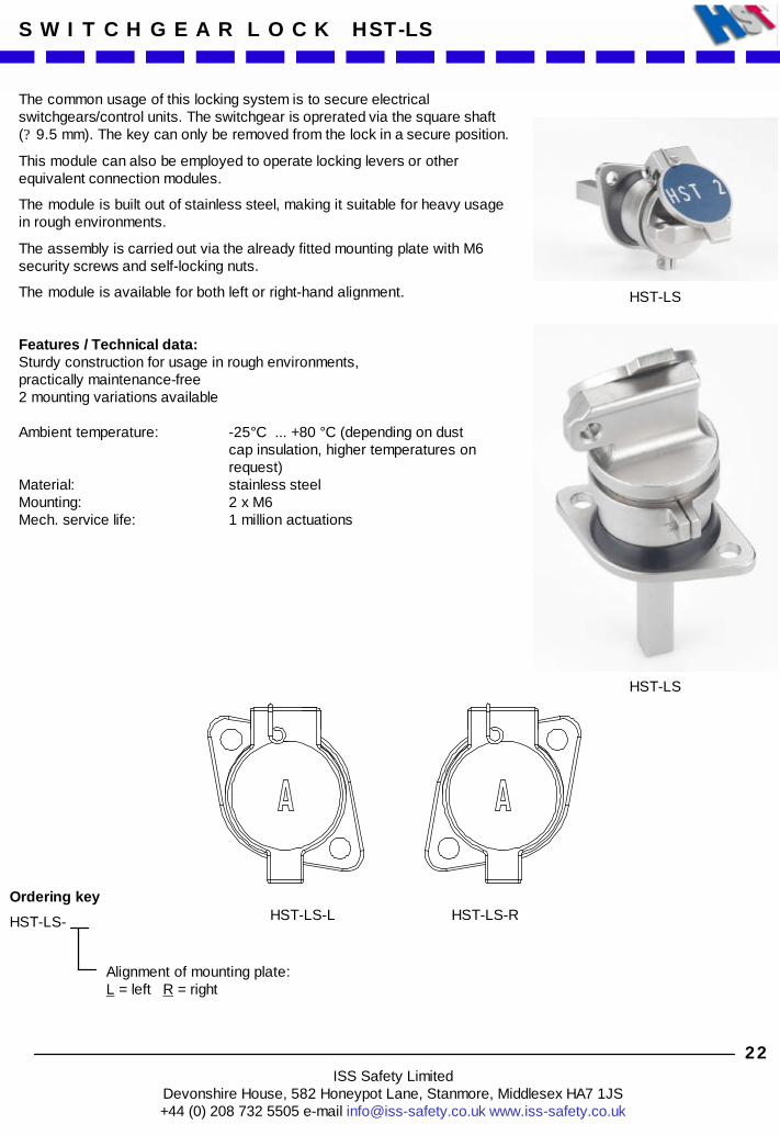
The common usage of this locking system is to secure electricalswitchgears/control units. The switchgear is oprerated via the square shaft(? 9.5 mm). The key can only be removed from the lock in a secure position.
This module can also be employed to operate locking levers or otherequivalent connection modules.
The module is built out of stainless steel, making it suitable for heavy usagein rough environments.
The assembly is carried out via the already fitted mounting plate with M6 security screws and self-locking nuts.
The module is available for both left or right-hand alignment.
Features / Technical data:Sturdy construction for usage in rough environments,practically maintenance-free2 mounting variations available
Ambient temperature: -25°C ... +80 °C (depending on dustcap insulation, higher temperatures on request)
Material: stainless steelMounting: 2 x M6Mech. service life: 1 million actuations
Alignment of mounting plate:L = left R = right
HST-LS
HST-LS
HST-LS-L HST-LS-R
ISS Safety LimitedDevonshire House, 582 Honeypot Lane, Stanmore, Middlesex HA7 1JS+44 (0) 208 732 5505 e-mail [email protected] www.iss-safety.co.uk

23
Measurements:
S W I T C H G E A R L O C K HST-LS
ISS Safety LimitedDevonshire House, 582 Honeypot Lane, Stanmore, Middlesex HA7 1JS+44 (0) 208 732 5505 e-mail [email protected] www.iss-safety.co.uk

24
A C C E S S O R I E S
Ordering code
HST-XC
The module HST-XC can be employed as endpiece for the exchange unit. While using HST-XC the bolt of the last module of the exchange unit iscovered up.
The module is built out of stainless steel and is suitable for heavy usage in rough environments.
The assembly is equivalent to HST-X with 2 x M8 inner threads.
Features / Technical data:Sturdy construction for use in rough environments,practically maintenance-freeAmbient temperature: -25°C ... +80 °C (higher if HST-X
is built accordingly)Material: stainless steelMounting: 2 x M8
HST-XC
HST-XC
Measurements:
ISS Safety LimitedDevonshire House, 582 Honeypot Lane, Stanmore, Middlesex HA7 1JS+44 (0) 208 732 5505 e-mail [email protected] www.iss-safety.co.uk

25
E X A M P L E S
This example shows the shutting down of a machine with running-down time and a single safety door (part-body access). The rotary switch with solenoid HST-M... is used for this purpose. The machine control system generates a signal which is applied to the rotary switch solenoid after the machine has shut down and is stationary. Key A can now be turned, removed and used for opening the door interlock HST-TS... .
Switch with solenoidHST-MA1-22-24D
Code A
Door interlockHST-TS1-R
Code A
Signal
KeyA
ISS Safety LimitedDevonshire House, 582 Honeypot Lane, Stanmore, Middlesex HA7 1JS+44 (0) 208 732 5505 e-mail [email protected] www.iss-safety.co.uk

26
E X A M P L E S
This example shows the shutting down of a machine without running-down time and two safety doors (part-body access). The rotary switch HST-SU... is used for this purpose. After switching-off, key A can be removed from the rotary switch and be used for releasing the two B keys in the key exchange unit HST-X.... The two door interlocks HST-TZ... of the safety doors can be opened with the B keys.
Rotary switchHST-SU1-22
Code A
Door interlockHST-TZ1-UV
Code B
Door interlockHST-TZ1-UV
Code B
ModuleHST-X-E-H
Code A
2 x moduleHST-X-A-H
Code B
Exchange unit
KeyA
2 x keyB
ISS Safety LimitedDevonshire House, 582 Honeypot Lane, Stanmore, Middlesex HA7 1JS+44 (0) 208 732 5505 e-mail [email protected] www.iss-safety.co.uk

E X A M P L E S
This example shows the more complex shutdown of a precipitator (high voltage) in a power station with disconnector switches and earthing switches and a multitude of access openings (manholes). Firstly, 4 disconnector switches should be switched off and interlocked with the aid of bolt interlocks. 4 earthing switches are then activated and interlocked via an exchange unit using these keys. The door interlocks on the manholes (full-body access) can then be opened using the freed keys and a key exchange unit.
Bolt interlocks fordisconnector switches
Bolt interlocks forearthing switches
Door interlocks withpersonal key
Key exchange unit
27
A B C D
A B C D
E E E E
E E E E F
F
G
ISS Safety LimitedDevonshire House, 582 Honeypot Lane, Stanmore, Middlesex HA7 1JS+44 (0) 208 732 5505 e-mail [email protected] www.iss-safety.co.uk

E n q u i r y Please copy, fill out and return by fax
Firm: _________________ Name/Dept.: _______________ Fax: _________________
1. Number of doors to be interlocked:_______________________
2. If more than one door has to be interlocked, should it be possible to open ALL doors simultaneously?
NO No exchange unit necessary
YES Exchange unit necessary
3. Is full-body accessing of the safety door possible (hazardous area can be viewed)?
NO Single interlock version
YES Interlock with personal key necessary
4. Interlock version (depends on safety door configuration):
Right Left e.g. standard interlock or with chain, slam-type interlock
Top Bottom e.g. slam-type interlock
5. What engraving (max. 5 digits) is required on the key, in the lock and on the dust cap?
6. Has the machine a running-down time, or is access to the safety doors enabled by the machine control?
NO Single key switch
YES Switch with solenoid 24V DC
110V AC 230V AC
Mounted version in housing
Integrated version for panel
Mounted version in housing
Integrated version for panel
7. Desired contact configuration of built-in switch (for version with or without solenoid)
2 N.O. / 2 N.C. contacts 4 N.C. contacts (N.C means: the contact opens when the machine has been switched off and the key removed.)
28ISS Safety Limited
Devonshire House, 582 Honeypot Lane, Stanmore, Middlesex HA7 1JS+44 (0) 208 732 5505 e-mail [email protected] www.iss-safety.co.uk