Transverse kinematics of ions stored in an electrostatic ion beam trap
8
Nuclear Instruments and Methods in Physics Research A 547 (2005) 279–286 Transverse kinematics of ions stored in an electrostatic ion beam trap D. Attia a,b , D. Strasser a , O. Heber a , M.L. Rappaport c , D. Zajfman a, a Department of Particle Physics, Weizmann Institute of Science, Rehovot 76100, Israel b Laboratoire Kastler Brossel, E ´ cole Normale Supe´rieure et Universite´Pierre et MarieCurie, Boite 74, 4 Place Jussieu, F-75252 Paris CEDEX 05, France c Physics Services, Weizmann Institute of Science, Rehovot 76100, Israel Received 3 January 2005; received in revised form 14 March 2005; accepted 24 March 2005 Available online 10 May 2005 Abstract We present experimental results, as well as numerical simulations, for the transverse velocity distribution of ions stored in an electrostatic ion beam trap. The measurements indicate that the transverse velocity spread is about 1% of the longitudinal velocity, and that the ions fill the whole transverse stable phase space. We also demonstrate that ion losses from the trap due to multiple scattering with molecules from the residual gas is an important factor limiting the lifetime of the beam. r 2005 Elsevier B.V. All rights reserved. Keywords: Ion traps; Multiple scattering; Cooling 1. Introduction The use and development of ion trapping techniques, which started about 50 years ago [1], have led to a broad range of discoveries and new experiments in physics and chemistry. In particu- lar, one can cite high-precision spectroscopy, mass measurements, particle dynamics, nuclear and atomic processes and the measurement of funda- mental constants [2]. During the last few years, a new type of ion trap has been developed in which ion beams, instead of ion clouds, are trapped [3,4]. This new trap stores particles using only electro- static fields and works on a principle similar to that of an optical resonator. The main advantages of the trap are the possibility to trap fast (keV) beams without need of deceleration, the well- defined beam direction, easy access to the trapped beam by various probes, and simple requirements in terms of external beam injection. Different types of experiments have already been performed with ARTICLE IN PRESS www.elsevier.com/locate/nima 0168-9002/$ - see front matter r 2005 Elsevier B.V. All rights reserved. doi:10.1016/j.nima.2005.03.141 Corresponding author. Tel.: +972 8 9344537; fax: +972 8 9344166. E-mail address: [email protected] (D. Zajfman).
Transcript of Transverse kinematics of ions stored in an electrostatic ion beam trap

ARTICLE IN PRESS
0168-9002/$ - se
doi:10.1016/j.ni
�Correspondifax: +972 8 934
E-mail addre
(D. Zajfman).
Nuclear Instruments and Methods in Physics Research A 547 (2005) 279–286
www.elsevier.com/locate/nima
Transverse kinematics of ions stored in an electrostatic ionbeam trap
D. Attiaa,b, D. Strassera, O. Hebera, M.L. Rappaportc, D. Zajfmana,�
aDepartment of Particle Physics, Weizmann Institute of Science, Rehovot 76100, IsraelbLaboratoire Kastler Brossel, Ecole Normale Superieure et Universite Pierre et MarieCurie, Boite 74, 4 Place Jussieu,
F-75252 Paris CEDEX 05, FrancecPhysics Services, Weizmann Institute of Science, Rehovot 76100, Israel
Received 3 January 2005; received in revised form 14 March 2005; accepted 24 March 2005
Available online 10 May 2005
Abstract
We present experimental results, as well as numerical simulations, for the transverse velocity distribution of ions
stored in an electrostatic ion beam trap. The measurements indicate that the transverse velocity spread is about 1% of
the longitudinal velocity, and that the ions fill the whole transverse stable phase space. We also demonstrate that ion
losses from the trap due to multiple scattering with molecules from the residual gas is an important factor limiting the
lifetime of the beam.
r 2005 Elsevier B.V. All rights reserved.
Keywords: Ion traps; Multiple scattering; Cooling
1. Introduction
The use and development of ion trappingtechniques, which started about 50 years ago [1],have led to a broad range of discoveries and newexperiments in physics and chemistry. In particu-lar, one can cite high-precision spectroscopy, massmeasurements, particle dynamics, nuclear and
e front matter r 2005 Elsevier B.V. All rights reserve
ma.2005.03.141
ng author. Tel.: +972 8 9344537;
4166.
atomic processes and the measurement of funda-mental constants [2]. During the last few years, anew type of ion trap has been developed in whichion beams, instead of ion clouds, are trapped [3,4].This new trap stores particles using only electro-static fields and works on a principle similar tothat of an optical resonator. The main advantagesof the trap are the possibility to trap fast (keV)beams without need of deceleration, the well-defined beam direction, easy access to the trappedbeam by various probes, and simple requirementsin terms of external beam injection. Different typesof experiments have already been performed with
d.
ARTICLE IN PRESS
D. Attia et al. / Nuclear Instruments and Methods in Physics Research A 547 (2005) 279–286280
these traps, such as the measurement of metast-able state lifetimes of atomic and molecularions [5,6], the lifetimes of metastable negative ions[7,8], and electron impact detachment cross-sections of negative clusters [9]. Cluster coolinghas also been observed [10]. Interesting dynamicsof the ion motion have been discovered, such asself-bunching (due to the so-called negativemass instability phenomenon) and the possibilityof using simple phase space manipulation toreduce the velocity spread [11,12]. Electrostaticion storage rings [13,14] have also been usedduring the last several years in a variety ofexperiments [15,16].
Although the motion of the ions in the trapcan be readily simulated, no measurements ofthe transverse velocity distribution (TVD) of thestored beam have hitherto been performed.The TVD is needed to understand the trapp-ing efficiency, as well as the beam loss pro-cesses, especially the ones related to multiplescattering. We describe here the method thatwe have developed to characterize the TVD ofthe stored ions. The results are compared tonumerical trajectory simulations, which con-firm that multiple scattering is the dominantloss process in these traps, and that the avail-able area of the stable transverse phase spacedirectly influences the lifetime of the trappedion beam.
V
trapped beam
VzVzV4V2
V1 V3
Ion source
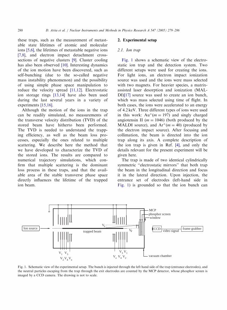
Fig. 1. Schematic view of the experimental setup. The bunch is injected
the neutral particles escaping from the trap through the exit electrod
imaged by a CCD camera. The drawing is not to scale.
2. Experimental setup
2.1. Ion trap
Fig. 1 shows a schematic view of the electro-static ion trap and the detection system. Twodifferent setups were used for creating the ions.For light ions, an electron impact ionizationsource was used and the ions were mass selectedwith two magnets. For heavier species, a matrix-assisted laser desorption and ionization (MAL-DI)[17] source was used to create an ion bunch,which was mass selected using time of flight. Inboth cases, the ions were accelerated to an energyof 4.2 keV. Three different types of ions were usedin this work: Auþðm ¼ 197Þ and singly chargedangiotensin II ðm ¼ 1046Þ (both produced by theMALDI source), and Arþðm ¼ 40Þ (produced bythe electron impact source). After focusing andcollimation, the beam is directed into the iontrap along its axis. A complete description ofthe ion trap is given in Ref. [4], and only thedetails relevant for the present experiment will begiven here.The trap is made of two identical cylindrically
symmetric ‘‘electrostatic mirrors’’ that both trapthe beam in the longitudinal direction and focusit in the lateral direction. Upon injection, theentrance set of electrodes (left-hand side inFig. 1) is grounded so that the ion bunch can
MCP
V
phosphor screen
V4 V2
V3 V1
rCCD
video signalframe grabber
vacuum chamber
window
through the left hand side of the trap (entrance electrodes), and
es are counted by the MCP detector, whose phosphor screen is
ARTICLE IN PRESS
D. Attia et al. / Nuclear Instruments and Methods in Physics Research A 547 (2005) 279–286 281
reach the exit mirror (right-hand side in Fig. 1),where they are reflected. Before the reflected bunchreaches the entrance electrodes, the potentials ofthese electrodes are rapidly switched on (�100 nsrise time) to the same values as those of the exitelectrodes. For proper choices of voltages, the ionsbounce back and forth between the two mirrors,their lifetime being limited mainly by collisionswith the residual gas molecules. The low pressurein the trap, of the order of 5� 10�10 Torr when theelectron impact source was used, and4� 10�11 Torr for the MALDI setup, is main-tained by a cryopump.
Each electrostatic mirror comprises eight elec-trodes. The potentials of the electrodes labeled V1
to V4 and V z in Fig. 1 are independentlyadjustable. The other electrodes are alwaysgrounded. Thus the 228mm long central regionof the trap between the two innermost electrodes isessentially field-free. The diameter of the centralhole is 16mm in the outer six electrodes and26mm in the two innermost electrodes. Thedistance between the outermost electrodes is407mm.
In order for the ions to be trapped, the electrodepotentials have to satisfy certain conditions. It iswell known that many principles of geometricoptics can be applied to ion optics. In fact, ourtrap is based on a optical resonator made of twocylindrically symmetric mirrors [18]. For anoptical resonator with identical mirrors and aGaussian beam, the stability criterion (for a beamclose to the symmetry axis) is related to thefocusing properties of the mirrors:
L=4pfp1, (1)
where f is the focal length of each mirror and L isthe distance between them. This condition is easyto fulfill with the above design. Another obviousrequirement is that the maximum potential on themirror axis, Vmax, has to be high enough to reflectthe ions , i.e., qVmax4Ek, where q is the charge ofthe ions and Ek is their kinetic energy.
Some important aspects of the design should beemphasized. First, the trap is completely electro-static, so there is no limit on the mass that can betrapped. Second, the trapping depends only on theratio Ek=q, which means that ions of different
mass that are accelerated through the samepotential difference can be stored simultaneously.Third, the central part of the ion trap is (nearly)field-free, so the ions travel in straight lines in thisregion.Various electrode voltage configurations are
possible to achieve trapping. We define a parti-cular configuration by the set of potentialsfV1;V2;V 3;V 4;Vzg. V z is connected to the centralelectrode of an Einzel lens that plays the majorrole in determining the focusing properties of themirrors. In the present work, only symmetricconfigurations, i.e., where identical potentials areapplied to the two mirrors, are considered. Thepotentials on the four outmost electrodes wereset to fV 1;V 2;V3;V4g ¼ f6:5; 4:875; 3:25; 1:65g kV,while the Einzel voltage was varied between2700oV zo3200V and 4000oV zo4300V. Thesetwo ranges correspond to the known values wherethe trap is stable, i.e., they satisfy the criterion Eq.(1), as has been shown in Ref. [18]. Additionaldetails about trapping stability and the compar-ison to optical models can be found in theliterature [18].
2.2. Detection system
One of the ion loss processes from the trap ischarge exchange, which leads to neutralization ofthe stored particles. These neutral particles passfreely through the mirrors and can be detected by amicrochannel plate (MCP) detector located down-stream of the trap (see Fig. 1). The detector iscoupled to a phosphor screen so that the spatialdistribution of the neutral particles exiting the trapcan be imaged. The location and size of the MCPwas different for the two different ion sourcesetups used in this work: The MCP was 25mm indiameter, and located at a distance of 80.3 cm fromthe center of the trap for the MALDI setup, whilefor the electron impact ionization source the MCPwas 40mm in diameter, and located at a distanceof 90.3 cm from the center of the trap. The imagingis performed by a charge-coupled device (CCD)camera located outside the vacuum that isconnected to a frame grabber which digitizes thepicture in real time. The first image is taken incoincidence with the raising of the potentials on

ARTICLE IN PRESS
D. Attia et al. / Nuclear Instruments and Methods in Physics Research A 547 (2005) 279–286282
the entrance mirror, and subsequent images aredigitized at a rate of 25Hz for the whole trappingtime (�1 s). The positions of impact ((x; y) on thefront surface of the MCP) are determined for allhits producing an amount of light (as measured bythe CCD camera) above a preprogrammed thresh-old. Images of about 50 to 150 injections areaveraged to produce statistically significant results.The radial coordinate r is calculated as
r ¼
ffiffiffiffiffiffiffiffiffiffiffiffiffiffiffiffiffiffiffiffiffiffiffiffiffiffiffiffiffiffiffiffiffiffiffiffiffiffiffiffiffiffiðx � x0Þ
2þ ðy � y0Þ
2q
, (2)
where (x0; y0) is the point where the trap axiscrosses the detector plane. This point is determinedat a later stage by finding the center of themeasured radial distribution.
2.3. Data analysis
In order to study the TVD inside the trap, weanalyze the radial distribution of the neutralparticles hitting the MCP detector. Fig. 1 showsthe relationship between the ion position andvelocity inside the trap at the instant of itsneutralization, and the point of impact of theneutralized particle on the detector, r. The ion’sposition at the neutralization point is given by itsdistance R from the optical axis of the trap anddistance from the MCP, s. The ion’s velocity at thesame point is defined in terms of its longitudinaland transversal velocities vk and v?, respectively(see Fig. 1). If we assume that the angularscattering taking place during the charge exchangeis small compared to the angular dispersion of thebeam (a very good approximation for the heavyions created in the MALDI source) [19], then theposition of impact on the MCP can be calculatedfrom
r ¼ R þsv?
vk. (3)
If we also use the fact that R r, then we obtainfor the transverse velocity
v? ¼rvk
s�
r
s
ffiffiffiffiffiffiffiffi2Ek
m
r, (4)
where m is the particle mass. Two problems arisefrom this simple formula: First, the velocities vk
and v? are not constant in the trap, as the particlesare slowed down and focused (or defocused, seeRef. [18]) inside the mirrors. Second, the exactdistance s between the neutralization point in thetrap and the MCP is unknown. The importance ofthese two effects, which can smear the radialdistribution measurement, will be treated sepa-rately using numerical simulation, as described inthe next section.
3. Numerical simulations
In order to verify the different approximationsmade in the derivation of Eq. (4), and to provide abetter understanding of the trap behavior, we haveperformed numerical simulations of the particletrajectories in the actual potentials of the ion trap.The calculations were carried out using SIMION[20], which can solve the Laplace equation for aspecific potential configuration in space andpropagate ions on the computed potential grid.The program uses a fourth-order Runge–Kuttamethod to solve the Newtonian equations ofmotion. The density of ions in the trap is assumedto be low enough for ion–ion interactions to beneglected, and the trajectories are calculated forone ion at a time (the actual number of ions in thetrap was of the order of 105 ions per injection).For different values of V z, while keeping the
other potentials constant, we have traced thestable trajectories, starting from an initial distribu-tion that covers the whole transverse stable (i.e.,trapped) phase space of the electrostatic trap, asdescribed in Ref. [18]. The stable phase space wasfound by systematically varying the initial condi-tions of the particles. A stable trajectory wasdefined as one for which a propagated ion wastrapped for more than 500 ms (about 200 oscilla-tions for 4.2 keV Arþ, or 90 for 4.2 keV Auþ). Itwas found that ions in unstable trajectories wereusually lost from the trap after a few oscillations(o20ms). The calculations were made using aconstant integration time step, and the positionsand velocities of the ions were recorded in a file ateach of these time steps. Using this information,simulated distributions for the radial distributionat the MCP were calculated by assuming an equal
ARTICLE IN PRESS
D. Attia et al. / Nuclear Instruments and Methods in Physics Research A 547 (2005) 279–286 283
probability for neutralization at each of theseintegration time steps, and propagating the (neu-tral) particles in straight lines, using the initialpositions and velocities as recorded. This methodhas the advantage of representing faithfully thelocal ion density along the length of the trap.Implicit in the assumption of equal probability ofneutralization in each time step is the assumptionthat the neutralization cross section is independentof kinetic energy for energies below 4.2 keV [21],even in the mirrors where the kinetic energiesapproach zero. The results can then be directlycompared to the experimental distributions.
4. Experimental and simulation results
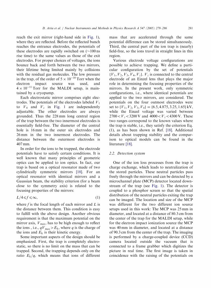
Fig. 2 shows a comparison between the mea-sured (dotted line) and simulated (solid line)normalized distributions for the distance squared(Pðr2Þ) at the MCP for 4.2 keV Auþ, andV z ¼ 3200V. We choose to plot the r2 distribu-tions as they display the radial density informationin the most relevant manner. The number ofparticles located in an interval of width dðr2Þ ¼
2rdr is proportional to the number of particles inthe ring between r and r þ dr, whose area is givenby 2prdr. Similar distributions were measured for
0 20 40 60 80 100 120 140 160 1800
0.005
0.01
0.015
0.02
0.025
0.03
r 2 (mm2)
P(r
2 )
Fig. 2. Normalized r2 distributions for 4.2 keV Auþ. Dotted
line: measured by the MCP detector; solid line: simulation with
Simion [20]. The Einzel lens voltage was 3200V.
Arþ and angiotensin IIþ ions. Each of themeasured distributions was characterized by thestandard deviation of the radial distribution whichin the present case is equal to the square root ofthe mean of r2: sr ¼
ffiffiffiffiffiffiffiffihr2i
p. Using Eq. (4), and
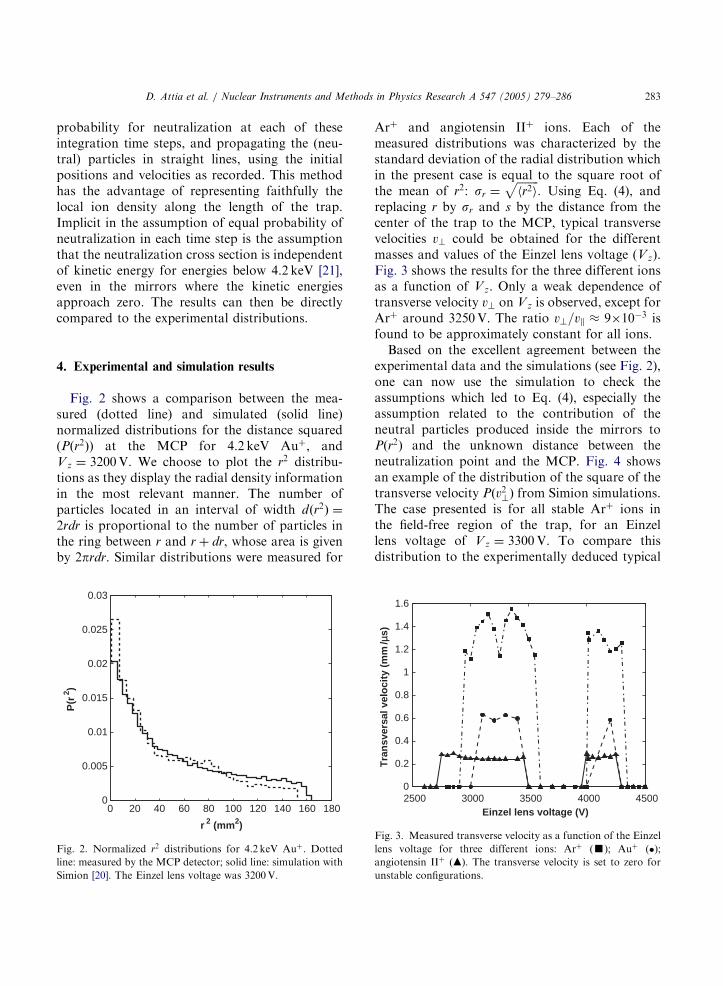
replacing r by sr and s by the distance from thecenter of the trap to the MCP, typical transversevelocities v? could be obtained for the differentmasses and values of the Einzel lens voltage (Vz).Fig. 3 shows the results for the three different ionsas a function of Vz. Only a weak dependence oftransverse velocity v? on Vz is observed, except forArþ around 3250V. The ratio v?=vk � 9�10�3 isfound to be approximately constant for all ions.Based on the excellent agreement between the
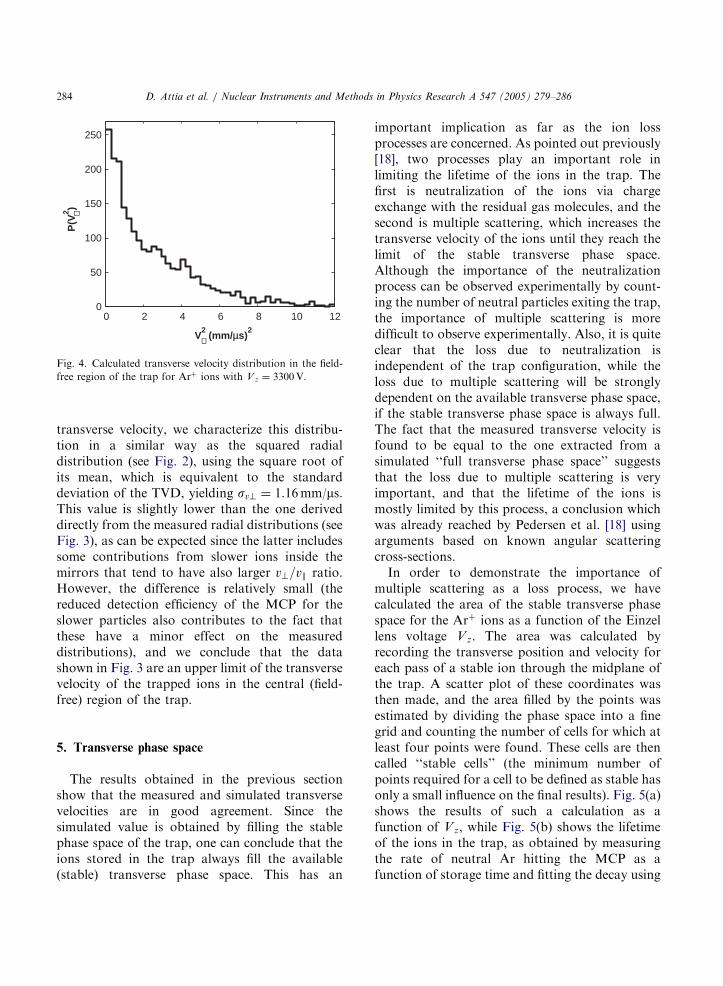
experimental data and the simulations (see Fig. 2),one can now use the simulation to check theassumptions which led to Eq. (4), especially theassumption related to the contribution of theneutral particles produced inside the mirrors toPðr2Þ and the unknown distance between theneutralization point and the MCP. Fig. 4 showsan example of the distribution of the square of thetransverse velocity Pðv2?Þ from Simion simulations.The case presented is for all stable Arþ ions inthe field-free region of the trap, for an Einzellens voltage of Vz ¼ 3300V. To compare thisdistribution to the experimentally deduced typical
2500 3000 3500 4000 45000
0.2
0.4
0.6
0.8
1
1.2
1.4
1.6
Einzel lens voltage (V)
Tra
nsv
ersa
l vel
oci
ty (
mm
/µs)
Fig. 3. Measured transverse velocity as a function of the Einzel
lens voltage for three different ions: Arþ (’); Auþ (�);
angiotensin IIþ (m). The transverse velocity is set to zero for
unstable configurations.
ARTICLE IN PRESS
0 2 4 6 8 10 120
50
100
150
200
250
V2 (mm/µs)
2⊥
⊥P
(V2 )
Fig. 4. Calculated transverse velocity distribution in the field-
free region of the trap for Arþ ions with V z ¼ 3300V.
D. Attia et al. / Nuclear Instruments and Methods in Physics Research A 547 (2005) 279–286284
transverse velocity, we characterize this distribu-tion in a similar way as the squared radialdistribution (see Fig. 2), using the square root ofits mean, which is equivalent to the standarddeviation of the TVD, yielding sv? ¼ 1.16mm/ms.This value is slightly lower than the one deriveddirectly from the measured radial distributions (seeFig. 3), as can be expected since the latter includessome contributions from slower ions inside themirrors that tend to have also larger v?=vk ratio.However, the difference is relatively small (thereduced detection efficiency of the MCP for theslower particles also contributes to the fact thatthese have a minor effect on the measureddistributions), and we conclude that the datashown in Fig. 3 are an upper limit of the transversevelocity of the trapped ions in the central (field-free) region of the trap.
5. Transverse phase space
The results obtained in the previous sectionshow that the measured and simulated transversevelocities are in good agreement. Since thesimulated value is obtained by filling the stablephase space of the trap, one can conclude that theions stored in the trap always fill the available(stable) transverse phase space. This has an
important implication as far as the ion lossprocesses are concerned. As pointed out previously[18], two processes play an important role inlimiting the lifetime of the ions in the trap. Thefirst is neutralization of the ions via chargeexchange with the residual gas molecules, and thesecond is multiple scattering, which increases thetransverse velocity of the ions until they reach thelimit of the stable transverse phase space.Although the importance of the neutralizationprocess can be observed experimentally by count-ing the number of neutral particles exiting the trap,the importance of multiple scattering is moredifficult to observe experimentally. Also, it is quiteclear that the loss due to neutralization isindependent of the trap configuration, while theloss due to multiple scattering will be stronglydependent on the available transverse phase space,if the stable transverse phase space is always full.The fact that the measured transverse velocity isfound to be equal to the one extracted from asimulated ‘‘full transverse phase space’’ suggeststhat the loss due to multiple scattering is veryimportant, and that the lifetime of the ions ismostly limited by this process, a conclusion whichwas already reached by Pedersen et al. [18] usingarguments based on known angular scatteringcross-sections.In order to demonstrate the importance of
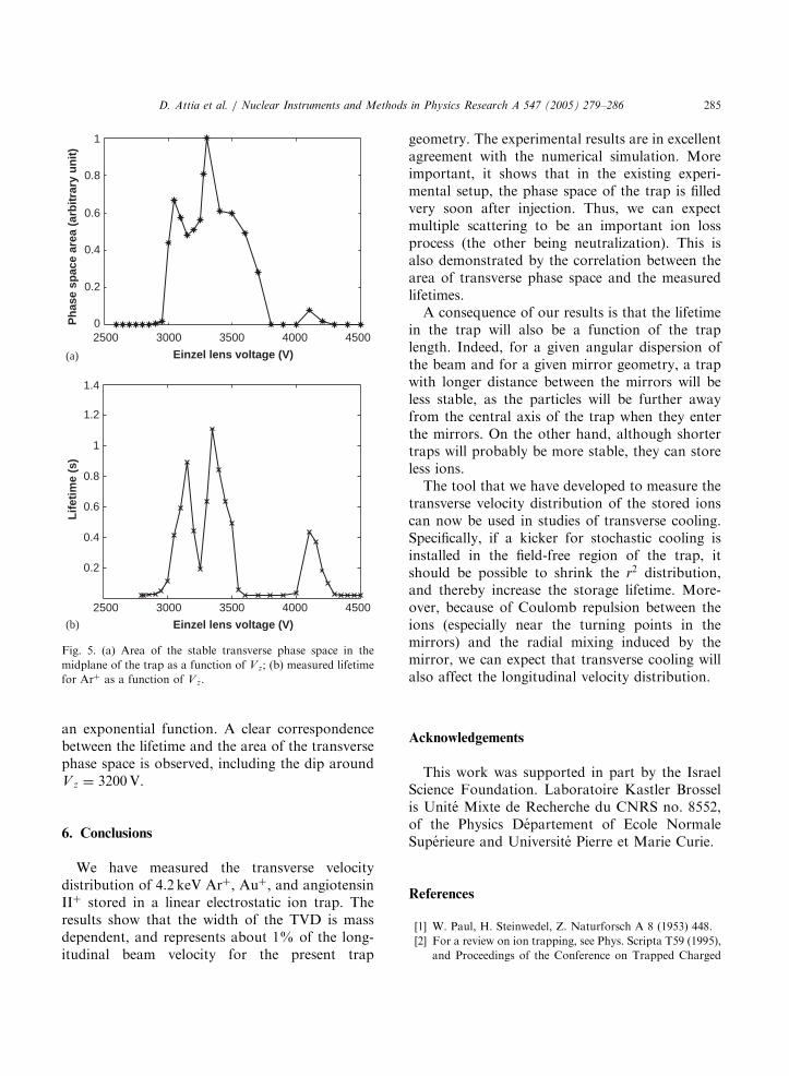
multiple scattering as a loss process, we havecalculated the area of the stable transverse phasespace for the Arþ ions as a function of the Einzellens voltage Vz. The area was calculated byrecording the transverse position and velocity foreach pass of a stable ion through the midplane ofthe trap. A scatter plot of these coordinates wasthen made, and the area filled by the points wasestimated by dividing the phase space into a finegrid and counting the number of cells for which atleast four points were found. These cells are thencalled ‘‘stable cells’’ (the minimum number ofpoints required for a cell to be defined as stable hasonly a small influence on the final results). Fig. 5(a)shows the results of such a calculation as afunction of Vz, while Fig. 5(b) shows the lifetimeof the ions in the trap, as obtained by measuringthe rate of neutral Ar hitting the MCP as afunction of storage time and fitting the decay using
ARTICLE IN PRESS
1
0.8
0.6
0.4
0.2
1.4
1.2
0.8
0.6
0.4
0.2
1
02500 3000 3500 4000 4500
Einzel lens voltage (V)
2500 3000 3500 4000 4500
Einzel lens voltage (V)
Ph
ase
spac
e ar
ea (
arb
itra
ry u
nit
)L
ifet
ime
(s)
(a)
(b)
Fig. 5. (a) Area of the stable transverse phase space in the
midplane of the trap as a function of V z; (b) measured lifetime
for Arþ as a function of V z.
D. Attia et al. / Nuclear Instruments and Methods in Physics Research A 547 (2005) 279–286 285
an exponential function. A clear correspondencebetween the lifetime and the area of the transversephase space is observed, including the dip aroundV z ¼ 3200V.
6. Conclusions
We have measured the transverse velocitydistribution of 4.2 keV Arþ, Auþ, and angiotensinIIþ stored in a linear electrostatic ion trap. Theresults show that the width of the TVD is massdependent, and represents about 1% of the long-itudinal beam velocity for the present trap
geometry. The experimental results are in excellentagreement with the numerical simulation. Moreimportant, it shows that in the existing experi-mental setup, the phase space of the trap is filledvery soon after injection. Thus, we can expectmultiple scattering to be an important ion lossprocess (the other being neutralization). This isalso demonstrated by the correlation between thearea of transverse phase space and the measuredlifetimes.A consequence of our results is that the lifetime
in the trap will also be a function of the traplength. Indeed, for a given angular dispersion ofthe beam and for a given mirror geometry, a trapwith longer distance between the mirrors will beless stable, as the particles will be further awayfrom the central axis of the trap when they enterthe mirrors. On the other hand, although shortertraps will probably be more stable, they can storeless ions.The tool that we have developed to measure the
transverse velocity distribution of the stored ionscan now be used in studies of transverse cooling.Specifically, if a kicker for stochastic cooling isinstalled in the field-free region of the trap, itshould be possible to shrink the r2 distribution,and thereby increase the storage lifetime. More-over, because of Coulomb repulsion between theions (especially near the turning points in themirrors) and the radial mixing induced by themirror, we can expect that transverse cooling willalso affect the longitudinal velocity distribution.
Acknowledgements
This work was supported in part by the IsraelScience Foundation. Laboratoire Kastler Brosselis Unite Mixte de Recherche du CNRS no. 8552,of the Physics Departement of Ecole NormaleSuperieure and Universite Pierre et Marie Curie.
References
[1] W. Paul, H. Steinwedel, Z. Naturforsch A 8 (1953) 448.
[2] For a review on ion trapping, see Phys. Scripta T59 (1995),
and Proceedings of the Conference on Trapped Charged
ARTICLE IN PRESS
D. Attia et al. / Nuclear Instruments and Methods in Physics Research A 547 (2005) 279–286286
Particles and Fundamental Interactions, J. Phys. B 36 (3,5)
(2002).
[3] D. Zajfman, et al., Phys. Rev. A 55 (1997) 1577.
[4] M. Dahan, et al., Rev. Sci. Instrum. 69 (1998) 76.
[5] R. Wester, K.G. Bhushan, N. Alstein, D. Zajfman, O.
Heber, M.L. Rappaport, J. Chem. Phys. 110 (1999) 11 830.
[6] K.G. Bushan, H.B. Pedersen, N. Alstein, O. Heber, M.L.
Rappaport, D. Zajfman, Phys. Rev. A 62 (2000) 012504.
[7] A. Wolf, K.G. Bhushan, I. Ben-Itzhak, N. Alstein, D.
Zajfamn, O. Heber, M.L. Rappaport, Phys. Rev. A 59
(1999) 267.
[8] L. Knoll, K.G. Bhushan, N. Alstein, D. Zajfman, O.
Heber, M.L. Rappaport, Phys. Rev. A 60 (1999) 1710.
[9] A. Diner, et al., Phys. Rev. Lett. 93 (2004) 063402.
[10] A. Naaman, et al., J. Chem. Phys. 113 (2000) 4662.
[11] H.B. Pedersen, D. Strasser, S. Ring, O. Heber, M.L.
Rappaport, Y. Rudich, I. Sagi, D. Zajfman, Phys. Rev.
Lett. 87 (2001) 055001-1.
[12] S. Goldberg, D. Strasser, O. Heber, M.L. Rappaport, A.
Diner, D. Zajfman, Phys. Rev. A 68 (2003) 043410.
[13] S.P. Møller, Nucl. Instr. and Meth. A 394 (1997)
281.
[14] S.P. Møller, U.V. Pedersen, Phys. Scripta T92 (2001) 105.
[15] U.V. Pedersen, M. Hyde, S.P. Møller, T. Andersen, Phys.
Rev. A 64 (2001) 012503-1.
[16] K. Hansen, J.U. Andersen, P. Hvelplund, S.P. Møller,
U.V. Pedersen, V.V. Petrunin, Phys. Rev. Lett. 87 (2001)
123401.
[17] F. Hillenkamp, et al., Anal. Chem. 63 (1991) 1193A.
[18] H.B. Pedersen, D. Strasser, O. Heber, M.L. Rappaport, D.
Zajfman, Phys. Rev. A 65 (2002) 042703.
[19] L.K. Johnson, R.S. Gao, C.L. Hakes, K.A. Smith, R.F.
Stebbings, Phys. Rev. A 40 (1989) 4920.
[20] SIMION, Version 6.0, Ion Source Software (http://
www.srv.net/�klack/simion.html).
[21] G.J. Lockwood, Phys. Rev. A 2 (1970) 1406.


![KINEMATICS - new.excellencia.co.innew.excellencia.co.in/college/web/pdf/Kinematics-merged.pdf · KINEMATICS KINEMATICS WORKSHEET 1 1) Displacement is a _____ [ ] 1) Vector quantity](https://static.fdocuments.in/doc/165x107/5f356d4687229051801abace/kinematics-new-kinematics-kinematics-worksheet-1-1-displacement-is-a-.jpg)