
Transport Analysis Report Summary Report Project …€¦ · IMO Sales number IA874E2nd edition...
26
ONLINE MARINE ENGINEERING Transport Analysis Report Summary Report Project EXAMPLE PROJECT Client ORCA OFFSHORE Issue Date 18/11/2010 Report reference number: Herm-18-Nov-10-40023 Report Prepared by: Online Marine Engineering www.transportanalysis.com Report template revision: R.1.5
Transcript of Transport Analysis Report Summary Report Project …€¦ · IMO Sales number IA874E2nd edition...

ONLINE MARINE ENGINEERING
Transport Analysis Report Summary Report
Project
EXAMPLE PROJECT
Client ORCA OFFSHORE
Issue Date 18/11/2010
Report reference number: Herm-18-Nov-10-40023 Report Prepared by: Online Marine Engineering www.transportanalysis.com
Report template revision: R.1.5

TRANSPORT ANALYSIS REPORT Summary report
EXAMPLE PROJECT
Page Date
: :
2 of 11 18/11/2010
ONLINE MARINE
ENGINEERING
TABLE OF CONTENTS 1.0� GENERAL ..................................................................................................................................... 4�
1.1� Introduction ................................................................................................................................ 4�
1.2� Scope ......................................................................................................................................... 4�
1.3� Design Criteria ........................................................................................................................... 4�
1.4� Bollard pull requirement ............................................................................................................. 5�
1.5� Design Velocity .......................................................................................................................... 6�
1.6� Cargo characteristics ................................................................................................................. 6�
1.7� Barge Characteristic .................................................................................................................. 6�
1.8� Barge Longitudinal Loading ....................................................................................................... 6�
2.0� SUMMARY OF RESULTS AND CONCLUSIONS ........................................................................ 8�
2.1� Summary of Results .................................................................................................................. 8�
2.2� Conclusions ............................................................................................................................... 8�
3.0� COMPUTER MODEL .................................................................................................................... 9�
3.1� General ...................................................................................................................................... 9�
3.2� Description of the barge model .................................................................................................. 9�
Attachment 1: Computer Output

TRANSPORT ANALYSIS REPORT Summary report
EXAMPLE PROJECT
Page Date
: :
3 of 11 18/11/2010
ONLINE MARINE
ENGINEERING
References 1. “General Guidelines for Marine Transportation”. Noble Denton International Limited, Rep No.
0030/NDI/JR Rev. 4, March 2010. 2. “Code on Intact Stability”. IMO Sales number IA874E2nd edition 2002, Resolution A.749(18) as
amended by resolution MSC.75(69). 3. “Online Moses Reference Manual”, UltraMarine 4. "Characteristics for Extreme Sea States on the Norwegian Continental Shelf", Torsethaugen et. al.
(1984), Technical Report No. STF60 A84123, Norwegian Hydrodyn. Lab., Trondheim.

TRANSPORT ANALYSIS REPORT Summary report
EXAMPLE PROJECT
Page Date
: :
4 of 11 18/11/2010
ONLINE MARINE
ENGINEERING
1.0 GENERAL
1.1 Introduction This report presents a full transport analysis on request of SPT Offshore b.v. for the EXAMPLE PROJECT Project. The report presents the used input data and a full report of the analysis. This report has been created online without any human interference. The client should carefully check the input and output before the results can be used. It is the sole responsibility of the client to assure that the results are correct.
1.2 Scope The scope of this report is to present the hydrostatic characteristics of this transport. The analysis includes: • Floatation analysis • Stability check according Noble Denton • Hydrodynamic motion analysis • Bollard-pull calculation • Barge Longitudinal Loading
1.3 Design Criteria This section presents the design criteria used for the transport.
1.3.1 Floating condition, - Static heel should be smaller than 0.5 degree. - Pitch should be between 0.0 to 0.2 degree aft down.
1.3.2 Stability requirements, The criteria as recommended by Noble Denton Association (NDA), ref. 1, will be followed. The following criteria will be checked for intact and damaged condition: 1. Intact Stability
• Minimum range of intact static stability: 36 Degree • Dynamic safety factor should be larger than 1.4
Alternatively, if maximum amplitudes of motion for the transport has been derived from motion response calculations, the intact range of stability shall be not less than;
(20 + 0.8θ) degree where θ = the maximum amplitude of roll or pitch caused by the design seastate, plus the static wind heel or trim caused by the design wind, in degrees. Furthermore the IMO intact stability requirements for pontoons, ref.2, need to be adhered to as well. • Area under the righting lever curve up to the angle of maximum righting lever should not be less
than 0.08 meter-radian ( = 4.58 m.degree) • The static angle of heel due to wind with speed 30 m/s (=58.4 knot) should not exceed and heel
angle corresponding to half the freeboard. For this transport the maximum wind heel should not exceed 7.2 Degree
• The minimum range of stability should be: • For L =< 100 m PRS>20 degree • For L= > 150 m PRS>15 degree • For intermediate length PRS by interpolation • For this pontoon minimum range = 20.0 Degree
TRANSPORT ANALYSIS REPORT Summary report
EXAMPLE PROJECT
Page Date
: :
5 of 11 18/11/2010
ONLINE MARINE
ENGINEERING
2. Damaged Stability The transport will be checked for one compartment stability using the following criteria:
• Minimum range of damaged static stability: 15 Degree • Dynamic safety factor should be larger than 1.4
1.3.3 Environmental conditions Design Storm For a weather unrestricted tow, the design storm for the transport shall be the 10 year return period monthly extreme storm for the planned route, reduced as appropriate for exposure of less than 30 days. The transport can also be classed as a weather restricted operations which allows the design environmental conditions to be set independent of extreme statistical data. The analysed design storm together with the planned route, duration and season determine weather this transport should be classed as restricted or unrestricted. The following conditions have been used for this analysis: Design Seastate Seastate Hs = 6.0 m, 8.8 < Tp < 13.4 sec The Tp range follows the recommendation of the Noble Denton Guideline reference 1. , To represent the seastate a Jonswap spectrum with a peak shape factor of 3.3 will be used without spreading. The following 5 headings will be used: 0 Stern 45 Quartering stern SB 90 Beam SB 135 Quartering bow SB 180 Head on MOSES will use T01 to define the seastate spectrum. The relation Tp/T01 has been based on the recommendation from Torsethagen et all, reference 4. Design Wind Intact The 1 minute mean wind velocity at 10 m above sealevel for the design storm shall be used for the overturning moment calculations. In the absence of appropriate wind data the following wind data shall be used:
• Intact condition: 100 kn • Damaged condition 50 kn
For this analysis the following wind data have been used:
• Intact Condition: 40.0 kn (1 min mean velocity @ 10 m above sealevel) • Damaged Condition: 40.0 kn (1 min mean velocity @ 10 m above sealevel)
Wind profile has been based on ABS.
1.4 Bollard pull requirement Minimum towline pull required (TPR) will be computed for zero forward speed against the following conditions acting simultaneously: • 20 m/s (40 kn)wind

TRANSPORT ANALYSIS REPORT Summary report
EXAMPLE PROJECT
Page Date
: :
6 of 11 18/11/2010
ONLINE MARINE
ENGINEERING
• Hs = 5.0 m seastate • 0.5 m/s current Minimum required static bollard pull of the tug(s) will be calculated as follows: BP = TPR / Te where Te = the tug efficiency factor. For this analysis a Te of 0.75 is used.
1.5 Design Velocity The design transport velocity will be 7 kn. This value will be used to estimate the tow resistance.
1.6 Cargo characteristics The following table presents the characteristics of the cargo that has been used for this analysis. No Name Weight LCG TCG VCG Roll
Radius
Pitch Radiu
s
Length
Width Height
- Ton m m m m m m m m
1 Accom 50.0 40.00 5.00 11.00 10.00 10.00 10.00 15.00 15.00
2 S1-S8 1200.0 -7.50 0.00 5.00 10.00 25.00 50.00 25.00 10.00
3 Flare 5.0 -40.00 0.00 20.00 60.00 60.00 4.00 4.00 40.00
Total 1255.0 -5.74 0.20 5.30
Table 1.2 Cargo characteristics Legend:
LCG = Longitudinal Centre of Gravity (From Midship to aft) TCG = Transverse Centre of Gravity (From Barge centreline to Starboard) VCG = Vertical Centre of Gravity (z) (From Barge deck upwards) Roll Radius = Roll Radius of Inertia Pitch Radius = Pitch Radius of Inertia Length = Length of Cargo Width = Width of cargo
1.7 Barge Characteristic The following cargo barge have been used: Name = Barge AMT Discoverer Model name = amt_Disc Length = 91.7 m Width = 30 m Depth = 7.6 m Lightship = 2325.00 Ton with VCG at 4.40 m above keel
1.8 Barge Longitudinal Loading The barge longitudinal loading has been calculated considering the weight distribution of the barge, cargo and ballastwater and the loading due to a hogging and sagging wave.

TRANSPORT ANALYSIS REPORT Summary report
EXAMPLE PROJECT
Page Date
: :
7 of 11 18/11/2010
ONLINE MARINE
ENGINEERING
The following wave has been used to calculate the longitudinal loading on the barge: Wave Length = 91.7 m Equal to the length of the barge Wave Height = 5.8 m Wave height has been based on the following empirical formula: 0.607*L^0.5 m

TRANSPORT ANALYSIS REPORT Summary report
EXAMPLE PROJECT
Page Date
: :
8 of 11 18/11/2010
ONLINE MARINE
ENGINEERING
2.0 SUMMARY OF RESULTS AND CONCLUSIONS
2.1 Summary of Results The transport with the barge Barge AMT Discoverer for project EXAMPLE PROJECT has been analysed with regard to intact and damaged stability and checked against the criteria as set by ref. 1.
2.2 Conclusions The hydrostatic analysis revealed that all intact stability requirements as set by Noble Denton Association (NDA), ref. 1, have been met. The hydrostatic analysis revealed that all intact stability requirements as set by the International Maritime Organisation (IMO), ref. 2, have been met. The hydrostatic analysis revealed that all damaged stability requirements as set by Noble Denton Association (NDA), ref. 1, have been met.

TRANSPORT ANALYSIS REPORT Summary report
EXAMPLE PROJECT
Page Date
: :
9 of 11 18/11/2010
ONLINE MARINE
ENGINEERING
3.0 COMPUTER MODEL
3.1 General This chapter presents the description of the model that has been used for the hydrostatic analysis of the transport. For the marine analysis, MOSES from Ultramarine, has been used. MOSES is a multipurpose marine and structural simulation computer program widely used for transport and installation design of offshore structures. See the ultramarine internet website for more information on MOSES, address is: http://www.ultramarine.com/ The computer model used for this run has been developed by Online Marine Engineering and bears revision code M.1.5.A.1.14.. The definition of the co-ordinate system for the marine analysis is as follows: Origin at barge centre, keel level and centre line. X-axis : Positive from barge bow towards stern Y-axis : Positive towards Starboard side Z-axis : Positive is upwards See figure 3.1.
Figure 3.1 Definition of marine co-ordinate system
3.2 Description of the barge model To calculate stability a single body model is used. This model consists of one rigid body composed of several compartments with the following properties: Compartment Type Remark Barge Standard Strip theory model Barge Ballast Tanks
Standard All tanks have been modelled
Table 3.1 Compartment properties The weights of all items have been modelled as point loads with correct inertia properties.
x
y
x
z
x
y
z

TRANSPORT ANALYSIS REPORT Summary report
EXAMPLE PROJECT
Page Date
: :
10 of 11 18/11/2010
ONLINE MARINE
ENGINEERING
ATTACHMENT 1: COMPUTER OUTPUT

TRANSPORT ANALYSIS REPORT Summary report
EXAMPLE PROJECT
Page Date
: :
11 of 11 18/11/2010
ONLINE MARINE
ENGINEERING

Page 1 Licensee - Online Marine Engineering Rev 7.03.040 Ser643 *************************************************************************************************************** * *** MOSES *** * * ---------------- 18 November, 2010 * * User: SPT Offshore b.v. NO.: 2 - EXAMPLE PROJECT * * Modeled weights * * * ***************************************************************************************************************
+++ B U O Y A N C Y A N D W E I G H T F O R M O D E L +++ =================================================================
Process is DEFAULT: Units Are Degrees, Meters, and M-Tons Unless Specified
Results Are Reported In Body System
Draft = 0.00 Roll Angle = 0.00 Pitch Angle = 0.00
Wet Radii Of Gyration About CG
K-X = 10.92 K-Y = 27.08 K-Z = 26.77
/-- Center of Gravity ---/ Sounding % Full Name Weight ---X--- ---Y--- ---Z--- -------- --------
---------------- Part AMT_DISC ------------ ---------------- Part CARGO1 ------------ LOAD_GRO 50.00 40.12 5.00 18.60 ---------------- Part CARGO2 ------------ LOAD_GRO 1200.00 -7.38 0.00 12.60 ---------------- Part CARGO3 ------------ LOAD_GRO 5.00 -39.88 0.00 27.60 ---------------- Part LIGHTSHI ------------ LOAD_GRO 2325.00 1.51 0.00 4.40 ---------------- Part MODEL ------------ ======== ======== ======= ======= ======= Total 3580.00 -0.99 0.07 7.38 Buoyancy 0.30 0.29 0.00 0.00
Page 2 Licensee - Online Marine Engineering Rev 7.03.040 Ser643 *************************************************************************************************************** * *** MOSES *** * * ---------------- 18 November, 2010 * * User: SPT Offshore b.v. NO.: 2 - EXAMPLE PROJECT * * Modeled weights * * * ***************************************************************************************************************
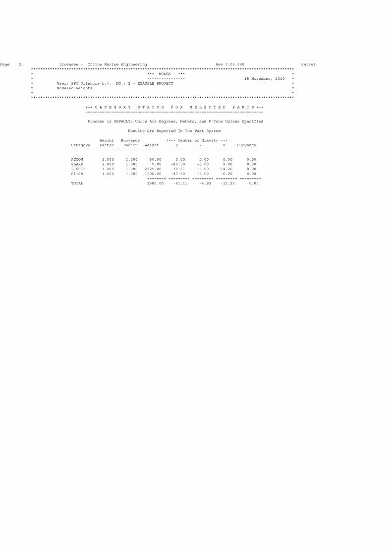
+++ C A T E G O R Y S T A T U S F O R S E L E C T E D P A R T S +++ ===========================================================================
Process is DEFAULT: Units Are Degrees, Meters, and M-Tons Unless Specified
Results Are Reported In The Part System
Weight Buoyancy /--- Center of Gravity --/ Category Factor Factor Weight X Y Z Buoyancy --------- --------- --------- -------- --------- --------- --------- ---------
ACCOM 1.000 1.000 50.00 0.00 0.00 0.00 0.00 FLARE 1.000 1.000 5.00 -80.00 -5.00 9.00 0.00 L_SHIP 1.000 1.000 2325.00 -38.61 -5.00 -14.20 0.00 S1-S8 1.000 1.000 1200.00 -47.50 -5.00 -6.00 0.00 ======== ========= ========= ========= ========= TOTAL 3580.00 -41.11 -4.93 -11.22 0.00

Page 3 Licensee - Online Marine Engineering Rev 7.03.040 Ser643 *************************************************************************************************************** * *** MOSES *** * * ---------------- 18 November, 2010 * * User: SPT Offshore b.v. NO.: 2 - EXAMPLE PROJECT * * Barge Hydrostatic Model check * * * ***************************************************************************************************************
+++ H Y D R O S T A T I C P R O P E R T I E S +++ ===================================================
For Body MODEL
Process is DEFAULT: Units Are Degrees, Meters, and M-Tons Unless Specified
/--- Condition ---//- Displac-/ /-- Center Of Buoyancy --// W.P. / /C. Flotation / /---- Metacentric Heights ----/ Draft Trim Roll M-Tons ---X--- ---Y--- ---Z--- Area ---X--- ---Y--- -KMT- -KML- -BMT- -BML-
0.00 0.00 0.00 0.30 0.29 0.00 0.00 2285 0.29 0.00 99999.99 99999.99 99999.99 99999.99 0.20 0.00 0.00 471.92 0.19 0.00 0.10 2317 0.08 0.00 389.60 2422.64 389.50 2422.54 0.40 0.00 0.00 949.89 0.09 0.00 0.20 2345 -0.08 0.00 196.09 1248.65 195.88 1248.45 0.60 0.00 0.00 1432.83 0.02 0.00 0.30 2368 -0.14 0.00 131.39 851.63 131.09 851.33 0.80 0.00 0.00 1920.32 -0.03 0.00 0.40 2390 -0.19 0.00 99.13 653.62 98.72 653.21 1.00 0.00 0.00 2412.30 -0.07 0.00 0.50 2411 -0.23 0.00 79.79 534.33 79.28 533.83 1.20 0.00 0.00 2908.37 -0.10 0.00 0.61 2430 -0.25 0.00 66.90 454.21 66.29 453.60 1.40 0.00 0.00 3408.42 -0.12 0.00 0.71 2450 -0.26 0.00 57.73 397.14 57.02 396.44 1.60 0.00 0.00 3912.47 -0.14 0.00 0.81 2469 -0.27 0.00 50.88 354.48 50.07 353.67 1.80 0.00 0.00 4420.51 -0.15 0.00 0.91 2489 -0.29 0.00 45.58 321.40 44.66 320.49 2.00 0.00 0.00 4932.55 -0.17 0.00 1.01 2508 -0.30 0.00 41.35 295.03 40.34 294.02 2.20 0.00 0.00 5448.58 -0.18 0.00 1.12 2528 -0.32 0.00 37.92 273.54 36.80 272.43 2.40 0.00 0.00 5968.60 -0.19 0.00 1.22 2547 -0.33 0.00 35.08 255.71 33.86 254.49 2.60 0.00 0.00 6492.61 -0.21 0.00 1.32 2567 -0.34 0.00 32.68 240.68 31.36 239.36 2.80 0.00 0.00 7020.62 -0.22 0.00 1.43 2586 -0.36 0.00 30.65 227.86 29.22 226.43 3.00 0.00 0.00 7552.62 -0.23 0.00 1.53 2606 -0.37 0.00 28.90 216.81 27.37 215.28 3.20 0.00 0.00 8088.61 -0.24 0.00 1.64 2625 -0.38 0.00 27.38 207.19 25.75 205.55 3.40 0.00 0.00 8628.60 -0.25 0.00 1.74 2645 -0.40 0.00 26.05 198.75 24.31 197.01 3.60 0.00 0.00 9172.58 -0.26 0.00 1.84 2664 -0.41 0.00 24.88 191.30 23.04 189.46 3.80 0.00 0.00 9720.55 -0.26 0.00 1.95 2683 -0.42 0.00 23.85 184.68 21.90 182.73 4.00 0.00 0.00 10272.52 -0.27 0.00 2.05 2703 -0.44 0.00 22.93 178.76 20.87 176.70 4.20 0.00 0.00 10828.48 -0.28 0.00 2.16 2722 -0.45 0.00 22.10 173.44 19.95 171.28 4.40 0.00 0.00 11388.43 -0.29 0.00 2.26 2742 -0.47 0.00 21.36 168.64 19.10 166.38 4.60 0.00 0.00 11952.35 -0.30 0.00 2.37 2760 -0.46 0.00 20.69 164.05 18.32 161.68 4.80 0.00 0.00 12518.95 -0.30 0.00 2.47 2769 -0.30 0.00 20.02 158.41 17.55 155.94 5.00 0.00 0.00 13087.47 -0.30 0.00 2.58 2779 -0.15 0.00 19.42 153.25 16.84 150.67 5.20 0.00 0.00 13657.89 -0.29 0.00 2.69 2787 -0.01 0.00 18.87 148.39 16.19 145.70 5.40 0.00 0.00 14229.09 -0.28 0.00 2.79 2787 -0.01 0.00 18.33 142.64 15.54 139.85 5.60 0.00 0.00 14800.29 -0.27 0.00 2.89 2787 -0.01 0.00 17.83 137.35 14.94 134.46 5.80 0.00 0.00 15371.50 -0.26 0.00 3.00 2787 -0.01 0.00 17.38 132.46 14.38 129.46 6.00 0.00 0.00 15942.70 -0.25 0.00 3.10 2787 -0.01 0.00 16.97 127.92 13.87 124.82 6.20 0.00 0.00 16513.90 -0.24 0.00 3.21 2787 -0.01 0.00 16.60 123.71 13.39 120.50 6.40 0.00 0.00 17085.11 -0.23 0.00 3.31 2787 -0.01 0.00 16.25 119.79 12.94 116.48 6.60 0.00 0.00 17656.31 -0.23 0.00 3.41 2787 -0.01 0.00 15.94 116.12 12.52 112.71 6.80 0.00 0.00 18227.51 -0.22 0.00 3.52 2787 -0.01 0.00 15.65 112.69 12.13 109.18 7.00 0.00 0.00 18798.72 -0.21 0.00 3.62 2787 -0.01 0.00 15.38 109.48 11.76 105.86 7.20 0.00 0.00 19369.92 -0.21 0.00 3.72 2787 -0.01 0.00 15.14 106.46 11.42 102.74 7.40 0.00 0.00 19941.12 -0.20 0.00 3.82 2787 -0.01 0.00 14.91 103.62 11.09 99.79 7.60 0.00 0.00 20512.32 -0.20 0.00 3.93 2787 -0.01 0.00 14.71 100.94 10.78 97.01 7.80 0.00 0.00 20569.79 -0.20 0.00 3.94 0 0.00 0.00 3.94 3.94 0.00 0.00

Page 4 Licensee - Online Marine Engineering Rev 7.03.040 Ser643 *************************************************************************************************************** * *** MOSES *** * * ---------------- 18 November, 2010 * * User: SPT Offshore b.v. NO.: 2 - EXAMPLE PROJECT * * Barge Hydrostatic Model check * * * ***************************************************************************************************************
+++ H Y D R O S T A T I C C O E F F I C I E N T S +++ =======================================================
For Body MODEL
Process is DEFAULT: Units Are Degrees, Meters, and M-Tons Unless Specified
Wetted Load To Change /----- For 0 KG -----/ /--- Condition ---/ Displacement Surface Draft 1 MM Moment To Change .01 Deg Draft Trim Roll ------------ --------- -------------- --- Heel --- --- Trim ---
0.00 0.00 0.00 0.30 2285.4 2.34 31.64 191.51 0.20 0.00 0.00 471.92 2349.8 2.37 32.08 199.53 0.40 0.00 0.00 949.89 2411.7 2.40 32.47 206.98 0.60 0.00 0.00 1432.83 2467.9 2.43 32.78 212.90 0.80 0.00 0.00 1920.32 2524.5 2.45 33.09 218.93 1.00 0.00 0.00 2412.30 2580.3 2.47 33.38 224.76 1.20 0.00 0.00 2908.37 2635.1 2.49 33.65 230.25 1.40 0.00 0.00 3408.42 2690.1 2.51 33.92 235.83 1.60 0.00 0.00 3912.47 2745.3 2.53 34.19 241.50 1.80 0.00 0.00 4420.51 2800.9 2.55 34.46 247.27 2.00 0.00 0.00 4932.55 2856.6 2.57 34.73 253.12 2.20 0.00 0.00 5448.58 2912.7 2.59 35.00 259.06 2.40 0.00 0.00 5968.60 2969.0 2.61 35.27 265.10 2.60 0.00 0.00 6492.61 3025.5 2.63 35.54 271.23 2.80 0.00 0.00 7020.62 3082.3 2.65 35.81 277.46 3.00 0.00 0.00 7552.62 3139.4 2.67 36.08 283.77 3.20 0.00 0.00 8088.61 3196.7 2.69 36.35 290.19 3.40 0.00 0.00 8628.60 3254.2 2.71 36.62 296.70 3.60 0.00 0.00 9172.58 3312.0 2.73 36.89 303.30 3.80 0.00 0.00 9720.55 3370.1 2.75 37.16 310.01 4.00 0.00 0.00 10272.52 3428.5 2.77 37.43 316.81 4.20 0.00 0.00 10828.48 3487.0 2.79 37.70 323.71 4.40 0.00 0.00 11388.43 3545.9 2.81 37.97 330.71 4.60 0.00 0.00 11952.35 3604.2 2.83 38.22 337.28 4.80 0.00 0.00 12518.95 3657.7 2.84 38.34 340.71 5.00 0.00 0.00 13087.47 3711.3 2.85 38.47 344.17 5.20 0.00 0.00 13657.89 3764.6 2.86 38.59 347.32 5.40 0.00 0.00 14229.09 3813.4 2.86 38.59 347.32 5.60 0.00 0.00 14800.29 3862.2 2.86 38.59 347.32 5.80 0.00 0.00 15371.50 3910.9 2.86 38.59 347.32 6.00 0.00 0.00 15942.70 3959.7 2.86 38.59 347.32 6.20 0.00 0.00 16513.90 4008.5 2.86 38.59 347.32 6.40 0.00 0.00 17085.11 4057.2 2.86 38.59 347.32 6.60 0.00 0.00 17656.31 4106.0 2.86 38.59 347.32 6.80 0.00 0.00 18227.51 4154.8 2.86 38.59 347.32 7.00 0.00 0.00 18798.72 4203.5 2.86 38.59 347.32 7.20 0.00 0.00 19369.92 4252.3 2.86 38.59 347.32 7.40 0.00 0.00 19941.12 4301.1 2.86 38.59 347.32 7.60 0.00 0.00 20512.32 5615.8 2.86 38.59 347.32 7.80 0.00 0.00 20569.79 8441.0 0.00 0.00 0.00

Page 5 Licensee - Online Marine Engineering Rev 7.03.040 Ser643 *************************************************************************************************************** * *** MOSES *** * * ---------------- 18 November, 2010 * * User: SPT Offshore b.v. NO.: 2 - EXAMPLE PROJECT * * Barge Compartments * * * ***************************************************************************************************************
+++ C O M P A R T M E N T P R O P E R T I E S +++ ===================================================
Results Are Reported In Body System
Process is DEFAULT: Units Are Degrees, Meters, and M-Tons Unless Specified
Fill Specific /--- Ballast ---/ /------ % Full --------/ Sounding Name Type Gravity Maximum Current Max. Min. Curr. --------
CP2 CORRECT 1.0247 939.3 0.0 0.00 0.00 0.00 0.000 CP3 CORRECT 1.0247 939.3 0.0 0.00 0.00 0.00 0.000 CP4 CORRECT 1.0247 939.3 0.0 0.00 0.00 0.00 0.000 CP5 CORRECT 1.0247 939.3 0.0 0.00 0.00 0.00 0.000 CS2 CORRECT 1.0247 939.3 0.0 0.00 0.00 0.00 0.000 CS3 CORRECT 1.0247 939.3 0.0 0.00 0.00 0.00 0.000 CS4 CORRECT 1.0247 939.3 0.0 0.00 0.00 0.00 0.000 CS5 CORRECT 1.0247 939.3 0.0 0.00 0.00 0.00 0.000 P1 CORRECT 1.0247 830.5 0.0 0.00 0.00 0.00 0.000 S1 CORRECT 1.0247 830.5 0.0 0.00 0.00 0.00 0.000 WP2 CORRECT 1.0247 939.3 0.0 0.00 0.00 0.00 0.000 WP3 CORRECT 1.0247 939.3 0.0 0.00 0.00 0.00 0.000 WP4 CORRECT 1.0247 939.3 0.0 0.00 0.00 0.00 0.000 WP5 CORRECT 1.0247 939.3 0.0 0.00 0.00 0.00 0.000 WP6 CORRECT 1.0247 828.8 0.0 0.00 0.00 0.00 0.000 WS2 CORRECT 1.0247 939.3 0.0 0.00 0.00 0.00 0.000 WS3 CORRECT 1.0247 939.3 0.0 0.00 0.00 0.00 0.000 WS4 CORRECT 1.0247 939.3 0.0 0.00 0.00 0.00 0.000 WS5 CORRECT 1.0247 939.3 0.0 0.00 0.00 0.00 0.000 WS6 CORRECT 1.0247 828.8 0.0 0.00 0.00 0.00 0.000

Page 6 Licensee - Online Marine Engineering Rev 7.03.040 Ser643 *************************************************************************************************************** * *** MOSES *** * * ---------------- 18 November, 2010 * * User: SPT Offshore b.v. NO.: 2 - EXAMPLE PROJECT * * BALLAST TANKS * * * ***************************************************************************************************************
+++ B U O Y A N C Y A N D W E I G H T F O R M O D E L +++ =================================================================
Process is DEFAULT: Units Are Degrees, Meters, and M-Tons Unless Specified
Results Are Reported In Body System
Draft = 3.80 Roll Angle = 0.00 Pitch Angle = 0.20
Wet Radii Of Gyration About CG
K-X = 10.50 K-Y = 25.72 K-Z = 25.80
GMT = 18.63 GML = 173.22
/-- Center of Gravity ---/ Sounding % Full Name Weight ---X--- ---Y--- ---Z--- -------- --------
---------------- Part AMT_DISC ------------ --- Contents --- CP2 247.54 -27.64 -3.81 1.00 2.01 26.35 CP3 287.00 -11.55 -3.81 1.16 2.33 30.55 CP4 326.47 4.55 -3.81 1.32 2.65 34.76 CP5 365.94 20.64 -3.81 1.48 2.97 38.96 CS2 246.30 -27.64 3.81 1.00 2.00 26.22 CS3 285.77 -11.55 3.81 1.16 2.32 30.42 CS4 325.24 4.55 3.81 1.32 2.64 34.62 CS5 364.70 20.64 3.81 1.48 2.96 38.83 P1 217.98 -38.29 -7.62 2.25 3.48 26.25 S1 215.51 -38.27 7.62 2.24 3.46 25.95 WP2 248.77 -27.64 -11.43 1.01 2.02 26.48 WP3 288.24 -11.55 -11.43 1.17 2.34 30.69 WP4 327.71 4.55 -11.43 1.33 2.66 34.89 WP5 367.18 20.64 -11.43 1.49 2.98 39.09 WP6 405.01 34.96 -11.43 2.38 4.35 48.87 WS2 245.06 -27.64 11.43 0.99 1.99 26.09 WS3 284.53 -11.55 11.43 1.15 2.31 30.29 WS4 324.00 4.55 11.43 1.31 2.63 34.49 WS5 363.47 20.64 11.43 1.47 2.95 38.69 WS6 401.29 34.94 11.43 2.37 4.32 48.42 ---------------- Part CARGO1 ------------ LOAD_GRO 50.00 40.12 5.00 18.60 ---------------- Part CARGO2 ------------ LOAD_GRO 1200.00 -7.38 0.00 12.60 ---------------- Part CARGO3 ------------ LOAD_GRO 5.00 -39.88 0.00 27.60 ---------------- Part LIGHTSHI ------------ LOAD_GRO 2325.00 1.51 0.00 4.40 ---------------- Part MODEL ------------ ======== ======== ======= ======= ======= Total 9717.71 0.37 0.00 3.65 Buoyancy 9717.71 0.37 0.00 1.95

Page 7 Licensee - Online Marine Engineering Rev 7.03.040 Ser643 *************************************************************************************************************** * *** MOSES *** * * ---------------- 18 November, 2010 * * User: SPT Offshore b.v. NO.: 2 - EXAMPLE PROJECT * * BALLAST TANKS * * * ***************************************************************************************************************
+++ C O M P A R T M E N T P R O P E R T I E S +++ ===================================================
Results Are Reported In Body System
Process is DEFAULT: Units Are Degrees, Meters, and M-Tons Unless Specified
Fill Specific /--- Ballast ---/ /------ % Full --------/ Sounding Name Type Gravity Maximum Current Max. Min. Curr. --------
CP2 CORRECT 1.0247 939.3 247.5 26.35 0.00 26.35 2.009 CP3 CORRECT 1.0247 939.3 287.0 30.55 0.00 30.55 2.329 CP4 CORRECT 1.0247 939.3 326.5 34.76 0.00 34.76 2.649 CP5 CORRECT 1.0247 939.3 365.9 38.96 0.00 38.96 2.970 CS2 CORRECT 1.0247 939.3 246.3 26.22 0.00 26.22 1.999 CS3 CORRECT 1.0247 939.3 285.8 30.42 0.00 30.42 2.319 CS4 CORRECT 1.0247 939.3 325.2 34.62 0.00 34.62 2.639 CS5 CORRECT 1.0247 939.3 364.7 38.83 0.00 38.83 2.960 P1 CORRECT 1.0247 830.5 218.0 26.25 0.00 26.25 3.484 S1 CORRECT 1.0247 830.5 215.5 25.95 0.00 25.95 3.463 WP2 CORRECT 1.0247 939.3 248.8 26.48 0.00 26.48 2.019 WP3 CORRECT 1.0247 939.3 288.2 30.69 0.00 30.69 2.339 WP4 CORRECT 1.0247 939.3 327.7 34.89 0.00 34.89 2.659 WP5 CORRECT 1.0247 939.3 367.2 39.09 0.00 39.09 2.980 WP6 CORRECT 1.0247 828.8 405.0 48.87 0.00 48.87 4.346 WS2 CORRECT 1.0247 939.3 245.1 26.09 0.00 26.09 1.989 WS3 CORRECT 1.0247 939.3 284.5 30.29 0.00 30.29 2.309 WS4 CORRECT 1.0247 939.3 324.0 34.49 0.00 34.49 2.629 WS5 CORRECT 1.0247 939.3 363.5 38.69 0.00 38.69 2.950 WS6 CORRECT 1.0247 828.8 401.3 48.42 0.00 48.42 4.316


FIGURE 2
User: SPT Offshore b.v. NO.: 2 - EXAMPLE PROJECT
Intact Stability check with Vessel amt_Disc L= 91.70m B= 30m D= 7.60m

FIGURE 3
User: SPT Offshore b.v. NO.: 2 - EXAMPLE PROJECT
Intact Stability check with Vessel amt_Disc L= 91.70m B= 30m D= 7.60m

FIGURE 4
User: SPT Offshore b.v. NO.: 2 - EXAMPLE PROJECT
Intact Stability check with Vessel amt_Disc L= 91.70m B= 30m D= 7.60m

FIGURE 5
User: SPT Offshore b.v. NO.: 2 - EXAMPLE PROJECT
Intact Stability check with Vessel amt_Disc L= 91.70m B= 30m D= 7.60m

FIGURE 6
User: SPT Offshore b.v. NO.: 2 - EXAMPLE PROJECT
BALLAST TANKS

FIGURE 7
CP2
CP3
CP4
CP5
CS2
CS3
CS4
CS5
P1
S1
WP2
WP3
WP4
WP5
WP6
WS2
WS3
WS4
WS5
WS6
User: SPT Offshore b.v. NO.: 2 - EXAMPLE PROJECT
BALLAST TANKS

FIGURE 8
CP2 26.4%
CP3 30.6%
CP4 34.8%
CP5 39.0%
CS2 26.2%
CS3 30.4%
CS4 34.6%
CS5 38.8%
P1 26.2%
S1 26.0%
WP2 26.5%
WP3 30.7%
WP4 34.9%
WP5 39.1%
WP6 48.9%
WS2 26.1%
WS3 30.3%
WS4 34.5%
WS5 38.7%
WS6 48.4%
User: SPT Offshore b.v. NO.: 2 - EXAMPLE PROJECT
BALLAST PLAN VESSEL amt_Disc L= 91.70m B= 30m D= 7.60m


![Commonwealth of Dominica...(c) International Safety Management Code [IMO Resolution A.741(18)] (d) ISM Code 2000 Amendments [IMO Resolution MSC.104(73)] (e) SOLAS 74 Chapter IX, Management](https://static.fdocuments.in/doc/165x107/6125418eb62bff6caf5ab263/commonwealth-of-c-international-safety-management-code-imo-resolution-a74118.jpg)


