Transponder Maintenance Manual -...
55
190-00420-05 January, 2007 Revision A GTX 328 Transponder Maintenance Manual
Transcript of Transponder Maintenance Manual -...

190-00420-05 January, 2007 Revision A
GTX 328TransponderMaintenanceManual

Page A GTX 328 Maintenance Manual Revision A 190-00420-05
© Copyright 2007 Garmin Ltd. or its subsidiaries
All Rights Reserved
Except as expressly provided herein, no part of this manual may be reproduced, copied, transmitted, disseminated, downloaded or stored in any storage medium, for any purpose without the express prior written consent of Garmin. Garmin hereby grants permission to download a single copy of this manual and of any revision to this manual onto a hard drive or other electronic storage medium to be viewed and to print one copy of this manual or of any revision hereto, provided that such electronic or printed copy of this manual or revision must contain the complete text of this copyright notice and provided further that any unauthorized commercial distribution of this manual or any revision hereto is strictly prohibited.
Garmin International, Inc. 1200 E. 151st Street
Olathe, KS 66062 USA Telephone: 913-397-8200
Aviation Dealer Technical Support Line (Toll Free): (888) 606-5482
www.garmin.com
Garmin (Europe) Ltd. Unit 5, The Quadrangle, Abbey Park Industrial Estate
Romsey, SO51 9DL, U.K. Telephone: 44/1794.519944
RECORD OF REVISIONS
Revision Revision Date Description ECO # A 01/05/07 Initial Release ---
DOCUMENT PAGINATION
Section Page Range Table of Contents i – vi
Section 1 1-1 – 1-16 Section 2 2-1 – 2-4 Section 3 3-1 – 3-2 Section 4 4-1 – 4-4 Section 5 5-1 – 5-8 Section 6 6-1 –6-4
Appendix A A-1 – A-16

GTX 328 Maintenance Manual Page i 190-00420-05 Rev A
NOTE
At the time of this revision, the current software version for the GTX 328 is 5.00. The software version and information in this document are subject to change without notice. Visit the Garmin web site (www.garmin.com) for current manual updates and supplemental information concerning the operation of this and other Garmin products.
INFORMATION SUBJECT TO EXPORT CONTROL LAWSThis document may contain information which is subject to the Export Administration Regulations ("EAR") issued by the United States Department of Commerce (15 CFR, Chapter VII, Subchapter C) and which may not be exported, released, or disclosed to foreign nationals inside or outside of the United States without first obtaining an export license. A violationof the EAR may be subject to a penalty of up to 10 years imprisonment and a fine of up to $1,000,000 under Section 2410 of the Export Administration Act of 1979. Include this notice with any reproduced portion of this document.
WARNING
This product, its packaging, and its components contain chemicals known to the State of California to cause cancer, birth defects, or reproductive harm. This Notice is being provided in accordance with California's Proposition 65. If you have any questions or would like additional information, please refer to our web site at www.garmin.com/prop65.
NOTE
Repair centers operated by Garmin Ltd. or its subsidiaries are authorized to perform component-level repairs to Garmin products. Repair centers operated by Garmin Ltd. or its subsidiaries are authorized to use Garmin proprietary documentation as references during any component-level repairs performed.

Page ii GTX 328 Maintenance Manual Rev A 190-00420-05
TABLE OF CONTENTS
PARAGRAPH PAGE
1. DESCRIPTION AND OPERATION................................................................................................ 1-11.1 INTRODUCTION............................................................................................................................. 1-1 1.2 EQUIPMENT DESCRIPTION......................................................................................................... 1-1 1.3 INTERFACE SUMMARY ............................................................................................................... 1-2 1.4 TRANSPONDER OPERATION ...................................................................................................... 1-3
1.4.1 ATCRBS System Operation .................................................................................................. 1-41.4.2 Interrogator ............................................................................................................................ 1-5 1.4.3 Transponder Mode A and Mode C Operation ....................................................................... 1-5 1.4.4 ATCRBS Transmission Overview......................................................................................... 1-6 1.4.5 ATCRBS Signals ................................................................................................................... 1-8
1.5 MODE S OVERVIEW...................................................................................................................... 1-9 1.5.1 Transponder Mode S Operation........................................................................................... 1-101.5.2 DPSK Pulse Characteristics ................................................................................................. 1-10 1.5.3 PAM Characteristics ............................................................................................................ 1-11 1.5.4 All Calls ............................................................................................................................... 1-12 1.5.5 Radar Screen, TCAS Display .............................................................................................. 1-12
1.6 MUTUAL SUPPRESSION PULSES ............................................................................................. 1-13 1.7 TECHNICAL SPECIFICATIONS ................................................................................................. 1-13 1.8 SCOPE OF MAINTENANCE ........................................................................................................ 1-14 1.9 EQUIPMENT DESCRIPTION....................................................................................................... 1-14
1.9.1 Main Board Assembly ......................................................................................................... 1-15 1.9.2 Front Panel ........................................................................................................................... 1-15 1.9.3 Transmitter........................................................................................................................... 1-15 1.9.4 Receiver ............................................................................................................................... 1-15 1.9.5 Flex Circuit Cables................................................................................................................. 1-16
2. SPECIAL TEST EQUIPMENT ........................................................................................................ 2-1 2.1 INTRODUCTION............................................................................................................................. 2-1 2.2 SPECIAL TOOLS AND TEST EQUIPMENT................................................................................. 2-1
2.2.1 Antenna Test Cable Connector .............................................................................................. 2-1 2.2.2 Transponder Bench Test ........................................................................................................ 2-2 2.2.3 Test Harness........................................................................................................................... 2-2 2.2.4 J3281 and Pin Assignment List.............................................................................................. 2-3

GTX 328 Maintenance Manual Page iii 190-00420-05 Rev A
3. TROUBLESHOOTING .................................................................................................................... 3-1 3.1 INTRODUCTION............................................................................................................................. 3-1 3.2 FAILURES........................................................................................................................................ 3-1
4. DISASSEMBLY AND REASSEMBLY .......................................................................................... 4-14.1 INTRODUCTION............................................................................................................................. 4-1 4.2 REQUIRED TOOLS......................................................................................................................... 4-1 4.3 DISASSEMBLING THE UNIT........................................................................................................ 4-1
4.3.1 Top Cover and Bottom Cover................................................................................................ 4-2 4.3.2 Pawl Latch Assembly ............................................................................................................ 4-2 4.3.3 Flexible Circuit Cable ............................................................................................................ 4-2 4.3.4 Front Panel Assembly ............................................................................................................ 4-3 4.3.5 Display Assembly .................................................................................................................. 4-3
4.4 REASSEMBLY ................................................................................................................................ 4-3 4.4.1 Display Assembly .................................................................................................................. 4-3 4.4.2 Front Panel Assembly ............................................................................................................ 4-3 4.4.3 Flexible Circuit Cables .......................................................................................................... 4-4
5. TESTING .......................................................................................................................................... 5-1 5.1 INTRODUCTION............................................................................................................................. 5-15.2 GENERAL ........................................................................................................................................ 5-1 5.3 ADJUSTMENT/MEASUREMENT ACCURACY .......................................................................... 5-1 5.4 TEST EQUIPMENT PRECAUTION ............................................................................................... 5-25.5 REQUIRED TEST EQUIPMENT .................................................................................................... 5-2
5.5.1 Test Harness........................................................................................................................... 5-2 5.6 SOFTWARE UPGRADE PROCEDURE......................................................................................... 5-2 5.7 BENCH TESTING............................................................................................................................ 5-3 5.8 STANDARD TEST SIGNALS......................................................................................................... 5-3
5.8.1 Input Voltages........................................................................................................................ 5-3 5.8.2 RF I/O .................................................................................................................................... 5-3
5.9 POWER ON CHECK........................................................................................................................ 5-3 5.9.1 28 V Panel Lighting............................................................................................................... 5-4 5.9.2 14 V Panel Lighting............................................................................................................... 5-4 5.9.3 5 V Panel Lighting................................................................................................................. 5-4 5.9.4 Power On Test ....................................................................................................................... 5-4 5.9.5 Display Dimming Test ........................................................................................................... 5-4
5.10 SWITCHED POWER OUTPUT....................................................................................................... 5-5 5.11 FRONT PANEL PUSHBUTTON CONTROLS............................................................................... 5-5
5.11.1 Code Selector Pushbutton Switches....................................................................................... 5-65.11.2 Configuration Pages............................................................................................................... 5-6
5.12 TIMER FUNCTIONAL TEST ......................................................................................................... 5-6

Page iv GTX 328 Maintenance Manual Rev A 190-00420-05
5.13 AUDIO TEST ................................................................................................................................... 5-7 5.14 EXTERNAL SWITCH STATE TEST.............................................................................................. 5-75.15 ARINC 429 AND RS-232 LOOPBACK TESTS ............................................................................. 5-7 5.16 FUNCTIONAL TEST....................................................................................................................... 5-7
6. PARTS AND ASSEMBLIES ........................................................................................................... 6-16.1 INTRODUCTION............................................................................................................................. 6-1 6.2 TABLES............................................................................................................................................ 6-1
APPENDIX A ASSEMBLY DRAWINGS.............................................................................................. A-1

GTX 328 Maintenance Manual Page v 190-00420-05 Rev A
LIST OF ILLUSTRATIONS
FIGURE PAGE
1-1 ATCRBS System............................................................................................................................... 1-4 1-2 Typical TCAS Encounter .................................................................................................................. 1-5 1-3 ATCRBS Interrogation without Side Lobe Suppression (SLS) ........................................................ 1-6 1-4 ATCRBS Interrogation with Side Lobe Suppression........................................................................ 1-7 1-5 ATCRBS Interrogation Pulses .......................................................................................................... 1-8 1-6 ATCRBS Reply Pulses...................................................................................................................... 1-9 1-7 Mode S DPSK interrogation ........................................................................................................... 1-10 1-8 PAM with P4................................................................................................................................... 1-12 1-9 GTX 328 Simplified System Block Diagram.................................................................................. 1-142-1 Blindmate Antenna Connector .......................................................................................................... 2-1 2-2 Rear Connector, J3281 Viewed From Rear Of Unit ......................................................................... 2-3 A-1 Assembly Drawing GTX 328 (Dwg. No. 015-00455-XX Rev. J) (Sheet 1 of 2) ............................ A-3 A-1 Assembly Drawing GTX 328 (Dwg. No. 015-00455-XX Rev. J) (Sheet 2 of 2) ............................ A-5 A-2 Sub-Assembly Front Panel (Dwg. No. 015-01683-XX Rev. A)...................................................... A-7 A-3 Sub-Assembly Display Module (Dwg. No. 015-00492-XX Rev. A)............................................... A-9 A-4 Sub-Assembly Bottom Cover......................................................................................................... A-11 A-5 GTX 328 Test Setup/Test Harness (Sheet 1 of 2) .......................................................................... A-13A-5 GTX 328 Test Setup/Test Harness (Sheet 2 of 2) .......................................................................... A-15
LIST OF TABLES TABLE PAGE
1-1 ATCRBS Pulse Position.................................................................................................................... 1-9 1-2 PAM Pulse Shape............................................................................................................................ 1-12 1-3 PAM Pulse Patterns......................................................................................................................... 1-12 2-1 P3281 Pin Assignments..................................................................................................................... 2-3 3-1 Testing Failures ................................................................................................................................. 3-1 5-1 Test Equipment ................................................................................................................................. 5-2 5-2 Audio Voltage/Frequency Test ......................................................................................................... 5-7 6-1 Sub-Assy., GTX 328 Black (Dwg. No. 015-00455-xx) .................................................................... 6-1 6-2 Sub-Assy., Front Panel Black (Dwg. No. 015-01683-xx)................................................................. 6-2 6-3 Sub-Assy., Display Module (Dwg. No. 015-00492-xx).................................................................... 6-3 6-4 Sub-Assy., Bottom Cover (Dwg. No. 115-00293-00)....................................................................... 6-3

Page vi GTX 328 Maintenance Manual Rev A 190-00420-05
GTX 328 HARDWARE MOD LEVEL HISTORY
The following table identifies hardware modification (Mod) Levels for the GTX 328 Mode S Transponder.Mod Levels are listed with the associated service bulletin number, service bulletin date, and the purpose of the modification. The table is current at the time of publication of this manual (see date on front cover) and is subject to change without notice. Authorized Garmin Sales and Service Centers are encouraged to access the most up-to-date bulletin and advisory information on the Garmin Dealer Resource web site at www.garmin.com using their Garmin-provided user name and password.
MODLEVEL
SERVICEBULLETINNUMBER
SERVICEBULLETIN
DATE
PURPOSE OF MODIFICATION

GTX 328 Maintenance Manual Page 1-1 190-00420-05 Rev A
SECTION 1
DESCRIPTION AND OPERATION
1.1 INTRODUCTION
This manual provides functional testing and assembly level maintenance information for the panel-mounted GTX 328 Mode S Transponder. Information pertaining to the installation and operating instructions can be found in the GTX 328 Installation Manual, 190-00420-04. This manual is designed to aid the bench technician in isolating failures to the assembly level only. If necessary, the GTX 328 can be returned to Garmin for all service work, including maintenance and repair. Contact Garmin at the following address or telephone numbers for more details:
Garmin International, Inc. 1200 E. 151st Street
Olathe, KS 66062 USA Telephone: 913-397-8200
Aviation Panel-Mount Technical Support Line (Toll Free): 1-888-606-5482www.garmin.com
1.2 EQUIPMENT DESCRIPTION
The Garmin GTX 328 is a Non-Diversity Mode S Transponder. The GTX 328 requires one antenna, intended to be bottom mounted. The design meets RTCA/DO-181C and EUROCAE ED-73A specifications.
The GTX 328 Mode S Transponder is a radio transmitter and receiver that operates on radar frequencies, receiving ground radar or TCAS interrogations at 1030 MHz and transmitting a coded response of pulses to ground-based radar on a frequency of 1090 MHz. The GTX 328 is equipped with IDENT capability that activates the Special Position Identification (SPI) pulse for 18 seconds.
The GTX 328 replies to ATCRBS Mode A, Mode C and Mode S All-Call interrogation. Mode A replies consist of any one of 4,096 codes, which differ in the position and number of pulses transmitted. Mode C replies include framing pulses and encoded altitude. Mode S interrogations are selective. The Mode S transponders can respond to a single directed interrogation from the ground station or another aircraft.
Ground stations interrogate Mode S Transponders individually using a 24-bit ICAO Mode S address, which is unique to the particular aircraft. In addition, ground stations may interrogate a GTX 328 for its Transponder data capability and the aircraft's Flight ID, which may be the registration number or other call sign. The GTX 328 makes the maximum airspeed capability (set via configuration pages, see Installation Manual, 190-00420-04, section 5) available to TCAS systems on-board nearby aircraft to aid in the determination of TCAS advisories.
In addition to displaying the code, reply symbol and mode of operation, the GTX 328 screen displays pressure altitude, density altitude, temperature, and timer functions, depending on equipment connections and configuration selection. The unit also features an altitude monitor and flight timers. A voice or tone audio output announces altitude deviation and count down timer expiration. The GTX 328 features multiple transmit/receive ARINC 429 and RS-232 data ports. The unit concentrates data from three ARINC 429 inputs, gray code, RS-232 input data and discrete inputs to the high-speed ARINC 429 output bus used by display systems such as the Garmin 400/500 Series units.

1-2 GTX 328 Maintenance Manual Rev A 190-00420-05
The GTX 328 is configured with all key controls. The layout of the front panel keys and displays segregates the transponder’s primary functions from the secondary functions. The unit can be configured so the aircraft avionics master bus can turn the unit on.
1.3 INTERFACE SUMMARY
The GTX 328 provides the following interface connections via the rear connector:
Ten (10) encoding altimeter inputs.
External IDENT input.
External STBY input (useful for dual transponder installations).
External suppression pulse input.
Switched power output of up to 1.5 amps (for digital altitude encoder power).
Aircraft dimming bus input voltage.
Aircraft master switch turn-on option.
Serial altitude or GPS groundspeed input.
Serial altitude input. (Reduces wire count vs. parallel wire gray code altimeter interface.)
Mode S. P/N 010-00634-( ) support Comm-A and Comm-B protocol.
Temperature, Altitude Hold and Density Altitude.
Digitally recorded voice and discrete warning annunciator activated by Altitude Hold when limits are exceeded.

GTX 328 Maintenance Manual Page 1-3 190-00420-05 Rev A
The GTX 328 P/N 010-00634-( ) supports the following list of Binary Data Selector (BDS) registers:
BDS (0,0) Air Initiated Comm-B (AICB)
BDS (1,0) Data Link Capability Report
BDS (1,7) Common Usage Ground Initiated Comm-B (GICB) Capability Report
BDS (1,8) Mode S Specific Services GICB Capability Report
BDS (1,9) Mode S Specific Services GICB Capability Report
BDS (1,D) Mode S Specific Services Protocols (MSP) Capability Report
BDS (2,0) Aircraft Identification
Note that BDS (3,0) is only required for transponders compatible with ACAS/TCAS II. The GTX 328 does not support BDS (3,0).
1.4 TRANSPONDER OPERATION
The Garmin GTX 328 Transponder System provides an air to ground link in the Air Traffic Control Radar Beacon System (ATCRBS) to report in-flight aircraft identification. It also provides air to air link participation in the airborne Traffic Alert and Collision Avoidance System (TCAS) for aircraft equipped with traffic avoidance equipment.
A pulsed interrogation from the ground-based secondary radar or airborne TCAS generates a pulsed reply from the GTX 328. These pulses are processed and displayed on an ATC radar screen on the ground or traffic display in other aircraft. Normal radar returns from the primary radar system vary in intensity depending on aircraft size, distance away and perhaps other factors. The transponder system equalizes returns by providing similar digital data for all aircraft.
Selected codes enable the transponder to reply with identification information useful to ATC. Special codes may be selected to indicate conditions such as emergency, VFR traffic or selected operations.
In addition to Mode A operation for identification, Mode C is employed for altitude information when an altitude encoder is connected to the transponder and altitude replies are selected.

1-4 GTX 328 Maintenance Manual Rev A 190-00420-05
1.4.1 ATCRBS System Operation
There are two classes of radar systems used by ATC, primary and secondary. Primary class includes surveillance or search radar. The secondary class is comprised of special purpose radar including ATC interrogators and transponders. Secondary radar is able to obtain selective encoded data that cannot be determined by primary radar alone. The secondary radar is officially referred to as the Air Traffic Control Radar Beacon System or ATCRBS. The essential elements of the ATCRBS are show in Figure 1-1.
Figure 1-1. ATCRBS System
PRIMARY RADAR RETURNS
INTERROGATION 1030 MHZ
REPLY 1090 MHZ
INTERROGATION ANTENNA SECONDARY RADAR
PRIMARY RADAR ANTENNA

GTX 328 Maintenance Manual Page 1-5 190-00420-05 Rev A
1.4.2 Interrogator
The ATC ground based interrogator rotates synchronously with the primary surveillance radar and transmits a sequence of pulses at a frequency of 1030 MHz. The interrogation repeatedly requests all transponders on the mode being used to reply. The received replies are available for display on the ATC radar screen.
There are five types of interrogation modes, A, B, C, D and S which may be transmitted by the ground station. Modes A, C, and S are covered in this manual. Mode B and Mode D are used by radar facilities in countries other than the United States. Each interrogation mode is distinct from the other and is characterized by the spacing of the transmitted framing pulses. The Garmin GTX 328 is designed for Mode A, Mode C and Mode S operation.
Similar to the ground based interrogator, an airborne TCAS processor transmits interrogation signals searching for airborne traffic in relatively close proximity. TCAS is capable of detecting the direction and altitude of an aircraft equipped with a transponder such as the Garmin GTX 328. Typical TCAS equipment is shown in Figure 1-2.
Figure 1-2. Typical TCAS Encounter
1.4.3 Transponder Mode A and Mode C Operation
When the interrogation signal is detected by the GTX 328, an appropriate response is generated. This response is transmitted omnidirectionally by the GTX 328 at a frequency of 1090 MHz. When multiple replies return to the interrogating system, appropriate equipment processes the identification, altitude, distance and azimuth data to compute location, speed and direction information for appropriate use.
TCAS DISPLAY
TCAS EQUIPPED AIRCRAFT
INTERROGATION 1030 MHZ
REPLY 1090 MHZ

1-6 GTX 328 Maintenance Manual Rev A 190-00420-05
1.4.4 ATCRBS Transmission Overview
The Air Traffic Control Radar Beacon System (ATCRBS) interrogates aircraft with either Mode A or Mode C. The Mode A interrogation requests the aircraft (4096) identification code. The Mode C interrogation requests the aircraft altitude. Any aircraft in the beam of the radar replies.
Side Lobe Suppression (SLS) is a technique used to prevent aircraft from replying when they are not in the main beam. The problem stems from the interrogation signals leaking from the directional antenna. The leaking signals are called side lobes. Even though the antenna is directional, side lobes still radiate in all directions. Were it not for Side Lobe Suppression the transponder in aircraft 1, 2 and 3 in Figure 1-3 would respond to interrogations by the main beam and side lobes from the radar transmitter.
Figure 1-3. ATCRBS Interrogation without Side Lobe Suppression (SLS)

GTX 328 Maintenance Manual Page 1-7 190-00420-05 Rev A
To correct this phenomenon, a non-directional pulse, P2, is transmitted immediately following the leading pulse. When the aircraft is in the main beam, the amplitude of the second pulse is much less than that of the first pulse, thus the transponder replies. When the aircraft detects a side lobe interrogation, the second pulse is equal to or greater than the first pulse, therefore the transponder does not reply. The Side Lobe Suppression period is a 35 μs (microsecond) timeout to which the transponder does not accept any ATCRBS interrogation.
Figure 1-4, ATCRBS Interrogation with Side Lobe Suppression illustrates the relative amplitudes of the transmitted main lobe P1, P2 and side lobe signals. Aircraft 1 replies because it is in the main beam. With the extra Side Lobe Suppression pulse P2, Aircraft 2 and 3 would not reply because they are in the side lobes.
Figure 1-4. ATCRBS Interrogation with Side Lobe Suppression

1-8 GTX 328 Maintenance Manual Rev A 190-00420-05
1.4.5 ATCRBS Signals
The 1030 MHz ATCRBS interrogations transmitted from the ground have Mode A interrogation modulated with two 0.8 μs pulses separated by 8 μs. The Mode C interrogation is modulated with two 0.8 μs pulses separated by 21 μs as shown in Figure 1-5. ATCRBS modulation is known as Pulse Amplitude Modulation (PAM).
Side Lobe Suppression (SLS) is the combination of the normal ATCRBS Interrogation and the non-directional pulse, P2. P2 is transmitted 2 μs after P1. Therefore when the aircraft is in the main beam, the amplitude of P2 is less than P1. When the aircraft receives a side lobe, P2 is equal to or greater than P1. The transponder does not transmit when P2 is greater than P1.
Figure 1-5. ATCRBS Interrogation Pulses

GTX 328 Maintenance Manual Page 1-9 190-00420-05 Rev A
Each ATCRBS reply, transmitted from the transponder at 1090 MHz, uses two framing pulses, F1 and F2, nominally spaced 20.3 ±0.1 μs apart. See Figure 1-6 ATCRBS Reply Pulses.
The Special Position Identification (SPI) Pulse is placed at a spacing 4.35 μs following the last framing pulse (F2) of Mode A replies only.
Figure 1-6. ATCRBS Reply Pulses
The designators of the information pulses and their positions from the first framing pulse (F1) are listed in Table 1-1, ATCRBS Pulse Position.
Table 1-1. ATCRBS Pulse Position
PULSE POSITION C1 F1+1.45 µs A1 F1+2.90 µs C2 F1+4.35 µs A2 F1+5.80 µs C4 F1+7.25 µs A4 F1+8.70 µs
X (Not Used) F1+10.15 µs B1 F1+11.60 µs D1 F1+13.05 µs B2 F1+14.50 µs D2 F1+15.95 µs B4 F1+17.40 µs D4 F1 + 18.85 µs
1.5 MODE S OVERVIEW
The ATCRBS system has certain limitations. The more airplanes there are in the sky, the more replies the ground station receives, causing a cluster of replies to overlap. The overlapping signals interfere with each other, thus the reception can be garbled and unusable. Mode S was developed to selectively address each transponder so that only one transponder replies at a time.
Mode S operates on the same frequencies as the ATCRBS transponder, therefore the Mode S system must operate without affecting the current ACTRBS transponders. In addition the Mode S transponders must operate in the ATCRBS system. Two new interrogation types were created:
Differential Phase Shift Keying (DPSK) and Pulse Amplitude Modulation (PAM) with P4 pulses.

1-10 GTX 328 Maintenance Manual Rev A 190-00420-05
1.5.1 Transponder Mode S Operation
The selective address of Mode S operation is a longer pulse format than Mode A and Mode C operation because the data string contains more information. Due to the longer Mode S transmission, it also requires a longer time of interrogation.
The GTX 328 responds to a query from a ground station or another aircraft when specifically interrogated by the selective string code. It replies with the data string containing type and identity information for each Mode S interrogation.
1.5.2 DPSK Pulse Characteristics
All Mode S (P6 type) interrogations contain Differential Phase Shift Keying (DPSK) modulation format. Interrogations are structured as shown in Figure 1-7. A P1-P2 pulse pair is transmitted in order to make ATCRBS transponders ignore the Mode S interrogations, causing the ATCRBS transponders to enter a Side Lobe Suppression (SLS) period, giving the Mode S transponders, at most, 35 μs to receive an interrogation.
0.8 s 0.8 sPOSSIBLE
PHASE REVERSAL POSITIONS
SYNC PHASEREVERSAL
FIRSTCHIP
LASTCHIP
P1 P2
2.0 s
1.25 s
2.75 s0.5 s
0.25 s 0.5 sP6
INTERROGATION
Figure 1-7. Mode S DPSK interrogation
The Pulse Amplitude Modulation (PAM) with P4 enables a Mode S ground station to interrogate ATCRBS transponders and still selectively address Mode S transponders. When a Mode S ground stations interrogates with a P4 short (.8 μs) only ATCRBS transponders reply. When a Mode S ground station interrogates with a P4 long (1.6 μs) ATCRBS transponders reply, and Mode S replies with a Downlink Format 11 (DF11). If a P4 pulse is not detected both the ATCRBS and Mode S transponders reply.
1.5.2.1 Pulse Shapes:
Pulses P1, P2 and P5 have the same shapes as PAM pulses P1, P2 and P3. P6 is either 16.25 ±0.25 μs, or 30.25 ±0.25 μs, in duration. P6 rise time is between 0.05 and 0.1 μs and the decay time is between 0.05 and 0.2 μs.

GTX 328 Maintenance Manual Page 1-11 190-00420-05 Rev A
1.5.2.2 Relative Pulse Amplitudes
P2 amplitude is not more than 0.25 dB less than the amplitude of P1. The first microsecond of P6 has amplitude not more than 0.25 dB less than the amplitude of P1. The amplitude variation of the envelope of P6 is less than 1 dB. The amplitude variation between successive phase modulation chips in P6 is less than 0.25 dB. P5 amplitude varies with respect to P6.
1.5.2.3 Phase Reversals
The first phase reversal within P6 is the sync phase reversal. The midpoint of each following data phase reversal occurs only at a time 0.25 times (N + 1) ±0.02 μs after the sync phase reversal, where N is a positive integer greater than one ( 1) and represents the bit number in the message for each bit that is equal to one.
1.5.2.4 Pulse Interval
P1 - P2 2.00 ±0.05 μs P2 to sync phase reversal of P6 2.75 ±0.05 μs P6 to sync phase reversal of P6 1.25 ±0.05 μs P5 to sync phase reversal of P6 0.4 ±0.05 μs P5 may be overlaid on P6 by the interrogator as a Side Lobe Suppression (SLS) signal in any Mode S interrogation. It is overlaid on all Mode S-Only All-Call interrogations.
1.5.2.5 Information Content
DPSK signals contain information in data chips within P6. The chips are located after the possible data phase reversals assigned as indicated in Figure 1-7. P6 pulses contain 56 chips (short) or 112 chips (long). A phase reversal preceding a chip characterizes that data bit as a binary ONE. No preceding phase reversal characterizes that data bit as a binary ZERO. The last 24 bits of P6 are overlaid with parity. The last 24 bits are also the address for each aircraft, except the Uplink Format 11 (UF11), which is an All-Call.
1.5.2.6 MODE S SUPPRESSION
The transponder enters suppression if the P1 and P2 preamble pulses of a Mode S interrogation are detected, but a sync phase reversal is not recognized. This requirement prevents the transponder from generating unwanted Mode A and/or Mode C replies to Mode S interrogations that are side lobe suppressed. Side Lobe Suppression for Mode S formats is characterized by the reception of P5, overlaying the location of the sync reversal of P6.
1.5.3 PAM Characteristics
Figure 1-8 shows the PAM with P4 pulse structure. Tables 1-3 and 1-4 summarize the PAM characteristics for ATCRBS and Mode S. The pulse shape for PAM interrogations are summarized in Table 1-3. The pulse patterns of the PAM interrogations are defined in Table 1-4. The Relative Pulse Amplitudes are as follows:
P3 amplitude is P1 1 dB. P4 amplitude is P3 1 dB.

1-12 GTX 328 Maintenance Manual Rev A 190-00420-05
Figure 1-8. PAM with P4
Table 1-2. PAM Pulse Shape
PulseDesignator
PulseDuration
DurationTolerance
Rise Time Min/Max
Decay Time Min/Max
P1,P2,P3,P5 0.8 µs ±0.1 µs 0.05/0.1 µs 0.05/0.2 µs P4 (short) 0.8 µs ±0.1 µs 0.05/0.1 µs 0.05/0.2 µs P4 (long) 1.6 µs ±0.1 µs 0.05/0.1 µs 0.05/0.2 µs
Table 1-3. PAM Pulse Patterns
INTERVAL (µs) INTERROGATION TYPE P1-P2 P1-P3 P3-P4 P4 TYPE Mode A 2 ±0.15 8 ±0.2 - None Mode C 2 ±0.15 21 ±0.2 - None Mode A/Mode S All-Call 2 ±0.15 8 ±0.2 2 ±0.05 Long Mode C/Mode S All-Call 2 ±0.15 21 ±0.2 2 ±0.05 Long Mode A-Only All-Call 2 ±0.15 8 ±0.2 2 ±0.05 Short Mode C-Only All-Call 2 ±0.15 21 ±0.2 2 ±0.05 Short
1.5.4 All-Calls
Once an aircraft is acquired by the ground station, the selective interrogation procedure is not self-sufficient.The radar requires continual updating of aircraft Mode S data and position. From one revolution of the radar antenna to the next, the radar estimates a new position for the aircraft and interrogates it when the antenna bearing is close to the expected new azimuth. This method of transponder reply works well in cruise flight, but the radar site is not able to maintain the sequence continually.
All-Call is a protocol that allows the Mode S aircraft to enter the coverage area and communicate simultaneously with their presence and identity without being selectively interrogated. The radar sends All-Calls periodically since it doesn’t know which way a new aircraft comes from, and for the change of location of the one that it is tracking.
1.5.5 Radar Screen, TCAS Display
The radar screen displays returns from both the primary surveillance radar system and ATCRBS. The ATC system controllers use these returns, called targets, to identify traffic. Similarly, the TCAS display indicates the presence of airborne traffic showing direction, distance and altitude.

GTX 328 Maintenance Manual Page 1-13 190-00420-05 Rev A
1.6 MUTUAL SUPPRESSION PULSES
Other equipment on board the aircraft may transmit in the same frequency band as the transponder, such as DME or another transponder. Mutual suppression is a synchronous pulse that is sent to the other equipment to suppress transmission of a competing transmitter for the duration of the pulse train transmission. The transponder transmission may be suppressed by an external source and other equipment on board may be suppressed by the transponder. This feature is designed to limit mutual interference.
1.7 TECHNICAL SPECIFICATIONS
Refer to the GTX 328 Installation Manual, 190-00420-04, for a complete list of specifications and Configurations Available.
SPECIFICATION CHARACTERISTIC
TSO, ETSO; GTX 328 TSO-C112, Class 2A1 121 010, ETSO-2C112s.
TSO ENV CAT Refer to GTX 328 Installation Manual, 190-00420-04, Appendix A
Temperature Range -45 C to +70 C (continuous operation)
Power Requirements 14/28 Vdc; Power Input: 22 watts typical, 45 watts maximum
Transmitter Frequency 1090 MHz
Transmitter Power 125 watts minimum, 250 watts nominal.
Receiver Frequency 1030 MHz
Receiver Sensitivity -74 dBm nominal for 90% replies
Mode A Capability 4096 Identification Codes
Mode C Altitude Capability 100 Foot Increments from -1000 to 62,700 feet.
Mode S Altitude Capability 25 Foot Increments from -1000 to 50,175 feet with suitable serial data altitude. 100 Foot Increments from -1000 to 62,700 feet.
Mode S Capability Selective Identification Codes, Aircraft Type, Aircraft ID, Comm-A, Comm-B
External Suppression Input Low 0.5 V; High 8 V, maximum is +33vDC
External Suppression Output Output: minimum is +18V (for 300 ohm load) and maximum of +23V (for 2000 ohm load).
Audio Output 4.04 Vrms to 7.85 Vrms into a 500 load

1-14 GTX 328 Maintenance Manual Rev A 190-00420-05
1.8 SCOPE OF MAINTENANCE
Garmin recommends limiting field maintenance to the following:
Functional inspection to meet current FAR requirements Limited replacement of major subassemblies Replacement of Flexible Circuit Cables
1.9 EQUIPMENT DESCRIPTION
The GTX 328 consists of five major electrical assemblies:
Main Board Assembly Receiver Board Transmitter Board Diplexer Board Front Panel Subassembly
Refer to figure 1-9 for a simplified block diagram.
DIPLEXER MAIN BOARDLCD DISPLAY
ANDKEYBOARD
TRANSMITTER
RECEIVER
Figure 1-9. GTX 328 Simplified System Block Diagram

GTX 328 Maintenance Manual Page 1-15 190-00420-05 Rev A
1.9.1 Main Board Assembly
The Main Board Assembly is the functional center of the unit. The Main Board communicates with all the components of the unit, and provides information to and from the Front Panel for the interface with the pilot. The Main Board contains the following circuits:
Power Supply Programmable Logic Device, EEPROM, microprocessor with flash and SRAM memory. Decoder/EncoderLight Dimming Circuit Switched Power Output I/O Filters RS-232 Circuitry
1.9.2 Front Panel
The Front Panel Subassembly provides the pilot/transponder interface. The Front Panel displays the timing and transponder functions and enters the selected code, SPI and timing commands. The Front Panel contains the following circuits:
LCD Display with LED backlighting Mode Selection Keys Pushbutton Data Entry Keys Ambient Light Sensor
1.9.3 Transmitter
The Transmitter transmits the coded pulses. The Transmitter contains the following circuits:
Pulse Modulator RF Amplifiers Voltage Regulators Transmit Sense/Monitor
1.9.4 Receiver
The Receiver receives the interrogation signals. The Receiver contains the following circuits:
970 MHz Local Oscillator 1030 MHz Bandpass filter 60 MHz IF frequency MixerDetectorReceiver Voltage Regulator Log Amplifier, Video Amplifier Rate Limiter Pulse Processing circuits

1-16 GTX 328 Maintenance Manual Rev A 190-00420-05
1.9.5 Flexible Circuit Cables
The major subassemblies are interconnected by ZIF (Zero Insertion Force) cables and ribbon cables. These cables are readily available from Garmin for replacement in case of damage.

GTX 328 Maintenance Manual Page 2-1 190-00420-05 Rev A
SECTION 2
SPECIAL TEST EQUIPMENT
2.1 INTRODUCTION
This section identifies the special test equipment essential to maintain the GTX 328. Standard equipment is not listed. For any questions regarding warranty repair of the unit contact the Garmin Customer Service Department at the address or phone number listed in Section 1.
2.2 SPECIAL TOOLS AND TEST EQUIPMENT
Transponder Test Set or equivalent (See Section 5.5) Power Supply OscilloscopeDigital Voltmeter 50 Antenna Test Cable Connector—Locally Fabricated Test Harness—Locally Fabricated (See Figure A-5, sheets 1 & 2) Coaxial Adapter: Female BNC to male type N
2.2.1 Antenna Test Cable Connector
The antenna test cable requires a BNC connector at the test fixture antenna and a male BNC “Blindmate” connector (Garmin P/N 330-00198-00) or RF Adapter (P/N 330-00326-00) at the GTX 328 Transponder.Instructions for installing the Blindmate BNC are shown in steps 1 through 7 and illustrated in Figure 2-1. Follow BNC connector manufacturer instructions for assembly of the BNC connector. The RF attenuation of the cable at 1090 MHz must not exceed 1.50 dB.
Figure 2-1. Blindmate Antenna Connector

2-2 GTX 328 Maintenance Manual Rev A 190-00420-05
1. Trim coax outer insulation back 0.50”.
2. Trim braid (not center conductor or insulation) back 0.25”.
3. Strip Insulation back 0.12”.
NOTEPlace the ferrule over the coax braid, flush against the coax outer insulation before performing the next step if the outside diameter of the coax braid is smaller than the inside diameter of the center connector sidewall opening.
4. Insert cable (center conductor, dielectric and shield braid) through the sidewall of the connector and solder the center conductor to the center pin of the connector.
NOTEWhen using low loss cable it may be necessary to flatten the solid wire center conductor slightly so it can fit the slot on the RF connector center pin. When soldering, avoid applying excess heat to the connector body, and center conductor insulator.
5. Heat the outside of the connector sleeve and at the same time apply solder between the braid and the sleeve. Continue to apply heat until the solder flows evenly.
6. Install 50 Matching Bushing.
7. Insert connector cap and tack solder in two places.
2.2.2 Transponder Bench Test
The Transponder Bench Test verifies the GTX 328 basic ATCRBS and Mode S operation:
Reply codes for Modes A and C Transmitter Frequency and Power Minimum Trigger Level (MTL) Side Lobe Suppression Receiver Dynamic Range Timer and Audio functions BacklightingARINC 429 and RS-232 Loopback operation Switched Power Output Remote Inputs (As listed in the test harness diagram)
2.2.3 Test Harness
A test harness must be fabricated to connect the GTX 328 to a suitable power source and Transponder Test Set.All electrical connections, except for the antenna, are made through a single, 62 pin D connector. Figure A-5 (sheets 1 & 2) defines the electrical characteristics of all input and output signals and identify the cable requirements for each signal. Connector orientation in the figure is viewed from the rear of the unit. Refer to Figure A-5 (sheets 1 & 2) Test Setup/Test Harness, when fabricating the test harness.

GTX 328 Maintenance Manual Page 2-3 190-00420-05 Rev A
2.2.4 J3281 and Pin Assignment List
123456789101112131415
222324252627282930313233343536
444647484950515253545556
161718192021
373839404142
575859606162
Figure 2-2. Rear Connector, J3281 Viewed From Rear Of Unit
Table 2-1. P3281 Pin Assignments
Connector P3281 Pin Pin Name I/O
1 AVIONICS MASTER ON SELECT In 2 ALTITUDE A1 In 3 ALTITUDE C2 In 4 ALTITUDE A2 In 5 ALTITUDE A4 In 6 ALTITUDE C4 In 7 ALTITUDE B1 In 8 ALTITUDE C1 In 9 ALTITUDE B2 In
10 ALTITUDE B4 In 11 ALTITUDE D4 In 12 EXTERNAL IDENT SELECT* In 13 EXTERNAL STANDBY SELECT* In 14 28 V LIGHTING BUS HI In 15 AUDIO OUT HI Out 16 AUDIO OUT LO Out 17 SQUAT SWITCH IN In 18 TEST MODE In 19 ALTITUDE ALERT ANNUNCIATE* Out 20 RESERVED -- 21 AIRCRAFT POWER 1 In 22 RS-232 IN 1 In 23 RS-232 OUT 1 Out 24 RS-232 IN 2 In 25 RS-232 OUT 2 Out 26 ARINC 429 IN 3 A In 27 POWER GROUND -- 28 ARINC 429 OUT 2 B Out 29 ARINC 429 IN 3 B In 30 ARINC 429 OUT 2 A Out 31 EXTERNAL SUPPRESSION I/O I/O
* Denotes Active Low (Ground to activate).

2-4 GTX 328 Maintenance Manual Rev A 190-00420-05
Table 2-1. P3281 Pin Assignments (Cont’d)
Connector P3281, continued Pin Pin Name I/O 32 ARINC 429 IN 1 A In 33 ARINC 429 IN 2 A In 34 ARINC 429 OUT 1 B Out 35 ARINC 429 IN 1 B In 36 ARINC 429 IN 2 B In 37 ARINC 429 OUT 1 A Out 38 RESERVED -- 39 RESERVED -- 40 SPARE -- 41 CURRENT TEMPERATURE PROBE OUT Out 42 AIRCRAFT POWER 1 In 43 POWER GROUND -- 44 CURRENT TEMPERATURE PROBE IN In 45 14 V/5 V LIGHTING BUS HI In 46 RESERVED -- 47 AUDIO MUTE SELECT* In 48 ARINC 429 IN 4 A In 49 ARINC 429 IN 4 B In 50 ALTITUDE COMMON (GROUND) In 51 RESERVED -- 52 RESERVED -- 53 RESERVED -- 54 RESERVED -- 55 SPARE -- 56 AIRCRAFT POWER 2 In 57 SPARE -- 58 RESERVED -- 59 SPARE -- 60 AIRCRAFT POWER 2 In 61 SPARE -- 62 SWITCHED POWER OUT Out
* Denotes Active Low (Ground to activate).

GTX 328 Maintenance Manual Page 3-1 190-00420-05 Rev. A
SECTION 3
TROUBLESHOOTING
The GTX 328 Transponder contains static sensitive components. Observe proper anti-static procedures when testing the unit.
3.1 INTRODUCTION
The GTX 328 Transponder contains limited field-replaceable parts. If necessary, the GTX 328 can be returned to Garmin International or Garmin (Europe) Ltd. for all service work, including maintenance and repair.
A faulty unit can be determined by completing the tests in Section 5, TESTING, and by completing Title 14 CFR Chapter 1, Part 43, Appendix F tests to the unit with a field test generator capable of performing these tests.
3.2 FAILURES
Table 3-1 lists recommended actions based on failures that can occur.
Table 3-1. Testing Failures
TEST FAILURE RECOMMENDED ACTION
Visual Inspection Replace damaged cables, Front Panel, or Top and Bottom Covers (See Section 4)
Power On Check If voltage is not measured at fuse F500, replace fuse on main board
Panel Lighting Replace Front Panel Assembly (see paragraphs 4.3.4)
Replace Display Module (see paragraphs 4.3.5)
Missing Pixels Replace Display Module (see paragraphs 4.3.5)
Push Button Response Replace Front Panel Assembly (see paragraphs 4.3.4)

3-2 GTX 328 Maintenance Manual Rev. A 190-00420-05
This page intentionally left blank

GTX 328 Maintenance Manual Page 4-1 190-00420-05 Rev. A
SECTION 4
DISASSEMBLY AND REASSEMBLY
4.1 INTRODUCTION
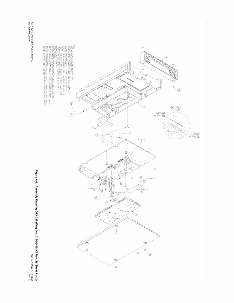
This section contains the instructions for removing the major assemblies of the GTX 328 Transponder. Reassembly instructions are given in paragraph 4.4. Disassemble the unit only to the extent necessary to remove and replace parts or assemblies affected. For aid in disassembly and reassembly refer to Section A, ASSEMBLY DRAWINGS for exploded views of the unit.
The GTX 328 contains static sensitive components. Observe proper ESD procedures while repairing the unit. Do not replace assemblies with the unit turned on. To avoid damaging the circuit boards and assemblies, the following procedures should be carefully followed.
4.2 REQUIRED TOOLS
Standard shop equipment is used to remove and replace faulty assemblies. No special tools are required.
NOTE
The GTX 328 lens is coated with a special anti-reflective coating which is very sensitive to skin oils, waxes and abrasive cleaners. CLEANERS CONTAINING AMMONIA WILL HARM THE ANTI-REFLECTIVE COATING. It is very important to clean the lens using an eyeglass lens cleaner which is specified as safe for anti-reflective coatings and a clean, lint free cloth.
4.3 DISASSEMBLING THE UNIT
NOTE
Numbers in parentheses refer to parts listed in tables in Section 6, and the circled figure number in Figures A-1 through A-5.

4-2 GTX 328 Maintenance Manual Rev A 190-00420-05
4.3.1 Top Cover and Bottom Cover (Figure A-1 sheets 1 & 2)
1. Remove four screws (23) securing the top cover (3) to the unit.
2. Remove six screws (23) securing the bottom cover assembly (4) to the unit.
3. Lift each cover at the rear, pulling backward until the retaining lip is fully exposed, then lift the cover off of the unit.
4.3.2 Pawl Latch Assembly (Figure A-4)
1. Remove four screws (3) attaching the locking pawl latch assembly (2) to the bottom cover (1).
4.3.3 Flexible Circuit Cable (Figure A-1)
NOTE
The GTX 328 employs a flexible circuit cable (19) to connect the main board assembly to the display module. The flat flexible cable is inserted into a Zero Insertion Force (ZIF) connector. Refer to figure A-1 for location.
1. Remove the top cover (3) as described in paragraph 4.3.1.
2. Carefully pull up on the retaining lip of the ZIF connector with a right-angle tool similar to a dental pick. The retaining lip will break if pulled too hard.
NOTE
Connectors may be coated with RTV to prevent cable disengagement. It is recommended that cables with RTV applied be replaced after disengagement. See Paragraph 4.4.3.
3. Gently pull the flexible circuit cable (19) from the connector.
4. Ribbon cables (20) are removed by grasping the blue connector and gently lifting up. The connectors are keyed to prevent incorrect replacement.

GTX 328 Maintenance Manual Page 4-3 190-00420-05 Rev. A
4.3.4 Front Panel Assembly (Figure A-1)
NOTE
To avoid damaging the unit, remove flexible circuit cables connecting the front panel assembly to the main circuit board assembly before removing the front panel assembly.
1. Remove the top cover (3) as described in paragraph 4.3.1.
2. Remove the flexible circuit cable (19) as described in paragraph 4.3.3.
3. Remove four black screws (22) in the front panel securing the front panel assembly to the main chassis.
4. Pull the front panel assembly forward off of the chassis (1).
4.3.5 Display Assembly (Figures A-2)
1. Remove the front panel assembly (2) as described in paragraph 4.3.4.
2. Remove the flexible circuit cable (19) from the ZIF connector if still attached.
3. Remove two screws (4) securing the display module (3) to the front panel assembly (1).
4. Carefully lift the display assembly off of the PCB connector, and then pull the display assembly sideways away from the retaining tabs on the front panel.
4.4 REASSEMBLY
4.4.1 Display Assembly (Figure A-2
1. Secure the two screws (4) securing the display module (3) to the front panel assembly (1).
4.4.2 Front Panel Assembly (Figure A-1)
1. Carefully place the front panel assembly (2) on the unit. Attach to the unit using four black screws (22) in the top holes in the bezel.
2. Install the flexible circuit cable (19) as described in paragraph 4.4.3.

4-4 GTX 328 Maintenance Manual Rev A 190-00420-05
4.4.3 Flexible Circuit Cables (Figure A-1)
1. With the retaining lip of the ZIF connectors lifted, carefully insert the flexible circuit cable (19) into the main board (4) and front panel ZIF connectors.
2. While gently holding the flexible circuit cable in the connector, press down on the connector lip to secure the cables in place.
3. Apply RTV (291-00039-00) (See Page A-1 Note 8) to both ends of the ZIF connector to prevent cable disengagement.
4. When installing the ribbon cables (20) carefully insert the connectors observing key orientation.

GTX 328 Maintenance Manual Page 5-1 190-00420-05 Rev A
SECTION 5
TESTING
5.1 INTRODUCTION
The test procedure in this section is provided to aid the technician in locating a faulty unit. The test procedure can be used to test a unit after it has been removed from an aircraft. All tests can be performed without accessing the inside of the unit.
The GTX 328 Transponder contains static sensitive components. Observe proper anti-static procedures when testing the unit.
WARNING
Hazardous voltages exist on the Main Board and Transmitter Board. Under normal operating conditions the voltages range up to 200 Vdc. Exercise extreme caution during unit testing. Death or serious injury could result from electrical shock.
5.2 GENERAL
This section includes testing procedures for units removed from an aircraft or from storage before use in an aircraft. Perform these tests with the dust covers on. After failure of a specific test the unit may be returned to the factory for repair.
After completing all necessary maintenance or service, perform the tests in this section, Section 5, TESTING.
5.3 ADJUSTMENT/MEASUREMENT ACCURACY
Before making any adjustments to the unit, ensure that all test equipment is in calibration and traceable to NIST (National Institute of Standards and Technology). Some output parameters are factory adjusted to specific levels. Test levels may not be accurate if the unit has been readjusted in the field.

5-2 GTX 328 Maintenance Manual Rev A 190-00420-05
5.4 TEST EQUIPMENT PRECAUTION
Except for the DVM with standard lead length, the case of each instrument should be connected to ground. The bench power supply ground must be connected to earth ground and serve as a single point ground for the entire test setup.
NOTE
Test harness misconnection could cause damage to the GTX 328 unit.
5.5 REQUIRED TEST EQUIPMENT
The following test equipment (or suitable substitute) listed in Table 5-1 is required for testing the GTX 328:
Table 5-1. Test Equipment
Test Equipment Description Representative Type Transponder Test Set, Mode S Test Set
Transponder field-test generator capable of performing Title 14 CFR Chapter 1, Part 43, Appendix F tests. Such as the TIC TR-220 for the GTX 328.
Power Supply Topward 2000 (+11 Vdc to +33 Vdc @ up to 3 amps if testing Switched Power Output)
Digital Multimeter Fluke Model 79 Oscilloscope: 100 MHz Bandwidth Minimum
Tek TDS-3034 or suitable equivalent
Garmin P/N 011-00583-00 Connector kit for SW Upgrade 9-Pin D-Sub Connector, Female 9-Pin Connector to attach to computer port for
SW Upgrade Test Harness Fabricated Locally (See Section 2) Coax Cable Assembly Fabricated Locally (See Section 2)
5.5.1 Test Harness
Figures A-5 (sheets 1 & 2) provide a schematic diagram for fabricating a suggested test harness. Instructions are also given in Figure 2-1 for assembling the blindmate connector on the Coax Cable Assembly. The Coax Cable Assembly is included as part of the test harness shown in Figure A-5.
5.6 SOFTWARE UPGRADE PROCEDURE
Software Version 5.00 is for the GTX 328 TSO C112 Class 2A units, P/Ns 011-01684-().
Refer to the latest Software Service Bulletin (SSB) for instructions on changing unit software. The unit's current software version is displayed at power up.

GTX 328 Maintenance Manual Page 5-3 190-00420-05 Rev A
5.7 BENCH TESTING Unless otherwise specified, this test is performed manually with covers in place. Attach a coax cable calibrated for 1.5 dB maximum attenuation at 1090 MHz with appropriate RF connectors.
5.8 STANDARD TEST SIGNALS
5.8.1 Input Voltages
Unless otherwise specified, all tests will be performed with power input voltages and RF signal as follows:
GTX 328 DC power input voltage per aircraft system of either +13.75 Vdc or +27.5 Vdc. Note that the GTX 328 will operate on any DC voltage between +11 and +33 Vdc. GTX 328 Panel Lighting input per aircraft voltage with unit configured accordingly.
5.8.2 RF I/O
The standard input test signal shall be 1090 MHz at –50 dBm with the PRF set to 500 per second. Set the test set RF Level to –50 dBm except for tests necessary to measure MTL, Dynamic Range or SLS performance.
5.9 POWER ON CHECK
Adjust the power supply voltages before connecting the unit. Verify that the GTX 328 has been correctly configured for the Panel Lighting voltage that will be used in the aircraft. Refer to the GTX 328 Installation Manual, 190-00420-04, for details.
1. Set the main power supply voltage to +27.5 Vdc or the actual aircraft voltage.
2. Set the panel lighting supply voltage as appropriate for the aircraft and apply this voltage to J3281 pin 14 or pin 45 through the test harness as specified in Figure 2-3.
3. Connect the GTX 328 to the Test Harness along with the RF coax connection and apply DC power.
4. Turn on the GTX 328 and complete the following tests:
NOTE
For units installed in a particular aircraft, you need check only the lighting voltage appropriate to that aircraft.

5-4 GTX 328 Maintenance Manual Rev A 190-00420-05
5.9.1 28 V Panel Lighting
1. Set panel lighting input voltage to +27.5 V and apply the voltage to the transponder test harness, pin 14.
2. Vary the panel lighting input voltage from +27.5 V to 0 V.
3. Observe that the panel lights continuously dim while reducing the lighting bus voltage.
5.9.2 14 V Panel Lighting
1. Set panel lighting input voltage to +13.75 V and apply the voltage to the transponder test harness, pin 45.
2. Vary the panel lighting input voltage from +13.75 V to 0 V.
3. Observe that the panel lights continuously dim while reducing the lighting bus voltage.
5.9.3 5 V Panel Lighting
1. Set panel lighting input voltage to +5 V and apply the voltage to the transponder test harness, pin 45.
2. Vary the panel lighting input voltage from +5 V to 0 V.
3. Observe that the panel lights continuously dim while reducing the lighting bus voltage.
5.9.4 Power On Test
1. Set main power supply voltage to +27.5 V.
2. Press any button (STBY, ALT or ON) on the GTX 328 power circle except OFF.
3. Observe that the display lights up when the button is pressed.
4. Verify correct indication on the GTX 328 front panel display, including mode selection, 4 digit code and time or altitude.
5.9.5 Display Dimming Test
1. Cover the ambient light sensor located next to the 7 key.
2. Observe that the display dims when the sensor is covered.
GTX 328 Maintenance Manual Page 5-5 190-00420-05 Rev A
5.10 SWITCHED POWER OUTPUT
Switched power output can be tested by supplying power to an encoding altimeter from the test harness, pin 62. Make sure that the current draw does not exceed 1.5 amps at +13.75 or 27.50 Vdc. At input voltages greater than +13.75 Vdc, the power supplied through the switched power output must not exceed the above rating.
Measuring voltage across a resistive load can also test switched power output. Verify that the voltage is within 1.5 volts of the input power.
5.11 FRONT PANEL PUSHBUTTON CONTROLS
Exercise all front panel pushbutton controls to verify proper selection and deselection of each LED and appropriate indication on the GTX 328 front panel display. The purpose of each function selection switch is as follows:
OFF Turns the GTX 328 off.
STBY Selects STBY mode.
ON Turns the transponder on without altitude reporting.
ALT Turns the transponder on with altitude reporting.
IDENT Activates the Special Position Identification (SPI) Pulse.
VFR Selects the default VFR code.
FUNC Changes modes displayed on the right side of the display. Displayed data includes Flight Level, Flight Time, Count Up timer, Count Down timer, screen Contrast, and Display Brightness (if configured for manual contrast and brightness).
Flight Level: Displays the pressure altitude data supplied to the GTX 328 in feet, flight level format or meters depending on configuration setup.
Flight Time: Displays the flight time controlled by the Start/Stop button. If AIRBORNE SOURCE is configured the timer begins when liftoff from a squat switch or when 35 knots from a GPS is sensed.
Count Up Timer: Controlled by START/STOP and CLR button. Count Down Timer: Controlled by START/STOP, CLR, and CRSR buttons. Count down
timer entered with 0 – 9 buttons. Contrast: Controlled by 8 and 9 buttons. Display Brightness: Controlled by 8 and 9 buttons.
START/ STOP Starts and stops the Count Up and Count Down timers.
CRSR Activates the change fields for the Count Down timer when selected by the FUNC key.
CLR Resets the Count Up and Count Down timers.

5-6 GTX 328 Maintenance Manual Rev A 190-00420-05
8 Reduces screen Contrast and display Brightness. Enters the number eight into the Count Down timer.
9 Increases screen Contrast and display Brightness. Enters the number nine into the Count Down timer.
5.11.1 Code Selector Pushbutton Switches
The code selector consists of eight push button (0 – 7) switches that provide 4,096 active identification codes.Pushing one of these buttons begins the code selection sequence. The new code will not be activated until the fourth button is pressed. While changing codes, pressing the CLR button moves the cursor to the previous digit. When on the first digit, pressing CLR restores the last active code. Pressing the CRSR button when data entry has begun will remove the cursor and cancel data entry. If an identification code entry is not completed the last active code is restored.
Check all eight code selection digits and code entry into the display. When checking the EXTERNAL SWITCH Page, verify the appropriate test harness switch operation.
5.11.2 Configuration Pages
Holding down the FUNC key and pressing the ON key provides access to the configuration pages. The FUNC key will sequence through the configuration pages. The CRSR key will highlight selectable fields on each page. When a field is highlighted, numeric data entry will be performed with the 0-9 keys, and list selections will be performed with the 8 or 9 keys. Press the CRSR key to accept changes. Pressing the FUNC key moves on to the next configuration page without saving the changes. Changes made through the configuration pages are stored in EEPROM memory. To exit the configuration pages, turn the power off and then on again (without holding the FUNC key).
Check each configuration page for proper data entry and display. Refer to the GTX 328 Installation Manual, 190-00420-04 for each configuration page detail.
5.12 TIMER FUNCTION TEST
Press the FUNC key and verify proper operation of the count up and count down timers.

GTX 328 Maintenance Manual Page 5-7 190-00420-05 Rev A
5.13 AUDIO TEST
The audio test is performed by measuring voltage and audio frequency across a 500 , 1/2 watt resistor connected between the audio high and low outputs, pins 15 and 16.
Cycle through the configuration pages with the FUNC key, accessing the Audio Mode (first) page. Select Message 0 for a continuous tone. Using the 9-key, adjust audio to full volume.
Measure the voltage across the resistor using the information given in Table 5-2.
Table 5-2. Audio Voltage/Frequency Test
AUDIO VOLTAGE 6.70 to 7.85 VRMS, FREQUENCY RANGE 490 Hz ±5 Hz
5.14 EXTERNAL SWITCH STATE TEST
When EXTERNAL IDENT, EXTERNAL STANDBY and SQUAT SWITCH discrete inputs are grounded the corresponding box field is filled on the display.
The EXTERNAL SWITCH STATE page is seen in both the configuration mode and test mode. Using the FUNC key, sequence through the configuration pages or test pages until the EXTERNAL SWITCH STATE page is in view.
5.15 ARINC 429 AND RS-232 LOOPBACK TESTS
With the unit off, enable the test mode using the test mode switch on the wiring harness. (The test mode switch applies a ground to P3281 pin 18). Turn the unit on in the test mode.
The FUNC key sequences through the configuration pages to display the LOOPBACK STATE Page.
When the appropriate ARINC 429 and RS-232 switches on the test harness are closed, the corresponding box field on the LOOPBACK STATE Page is filled on the display.
5.16 FUNCTIONAL TEST
Functional testing of the GTX 328 Transponder is performed by completing Title 14 CFR Chapter 1, Part 43, Appendix F tests required for a Class 2A Mode S transponder. Perform functional testing before returning a repaired unit to service. These measurements are applicable after a ten-minute warm-up period under standard conditions.
AUDIO MODE (First) Page
EXTERNAL SWITCH Page
LOOPBACK STATE Page

5-8 GTX 328 Maintenance Manual Rev A 190-00420-05
This page intentionally left blank

GTX 328 Maintenance Manual Page 6-1 190-00420-05 Rev A
SECTION 6
PARTS AND ASSEMBLIES
6.1 INTRODUCTION
This section of the manual lists major parts of the GTX 328. The part numbers listed in this section of the manual are given to aid in assembly and disassembly of the unit only, not for identifying orderable parts. For orderable part information including availability, see the Garmin Aviation Distributor Service Parts Price List or contact Garmin directly.
6.2 TABLES
The following tables contain equipment breakdowns to the assembly level. Included in the tables are part numbers that can be used with the corresponding illustrations in Appendix A for ease of identification.
The GTX 328 Transponder contains.
Table 6-1. Sub-Assy., GTX 328 Black (Dwg. No. 015-00455-xx, Figure A-1 sheets 1 & 2)
ReferenceDesignator
Part Number Item Description Quantity
145-00480-04 PMP,Bezel Cover,GTX327 1
291-00005-00 Sealant,Silicone,Gen Purpose 0
291-00039-00 RTV,Non-Flow,Non-Corrosive 0
14 330-00070-03 Conn,Coax,Blind Thd w/Groove 1
16 231-00020-01 Plug,BNC Hole,w/Nyl Lkg Patch 1
1 125-00028-00 DCP,Chassis,GTX 330 1
2 011-01683-00 Sub-Assy,GTX328,Front Panel, PD 1
3 115-00292-00 SMP,Top Cover,GTX330 1
4 115-00293-00 SMP,Bottom Cover Assy,GTX330 1
5 115-00384-00 SMP,Shield,TX Pocket,GTX330 1
6 012-00464-00 PCB Assy,GTX330 TX 1
7 012-00465-01 PCB Assy,GTX330 RX 1
8 012-00466-50 PCB Assy,GTX328 2A Mn Bd, SMT 1
9 012-00570-00 PCB Assy,GTX330 Diplexer Bd 1
10 161-01507-00 Tag,S/N,GTX328, Black, Pre TSO 1
11 250-00067-00 Thermal Pad,TX Bd,GTX327 5
12 250-00072-00 Thermal Pad,Square,GTX330 1
13 250-00073-00 Thermal Pad,GTX330,Main 1

Page 6-2 GTX 328 Maintenance Manual Rev A 190-00420-05
Table 6-1. Sub-Assy., GTX 328 Black (continued)
ReferenceDesignator
Part Number Item Description Quantity
17 334-00039-03 Header,Bd to Bd,2x5 3
19 310-00019-22 Ca,Flat Flex,.5mm,103mm,30 cond 1
20 325-00063-03 Ribbon Ca Stp,2mm Ctrs,2x5 1
21 311-00007-06 Wire,Bus Bar,Tin/Lead 24 Awg 0.5
22 211-60334-06 Screw,4-40x.187,PHP-STD,SS/BO, 4
23 211-60234-08 Screw,4-40x.250,PHP,SS/P,w/NYL 53
24 211-63234-10 Scr,4-40x.375,FLHP100,SS/P,Nyl 2
25 214-00023-03 Stdoff,M/F,Hex,4-40,.27"w/Nyl 1
26 115-00394-00 SMP,Cover,PLL,RX,GTX330 1
28 115-00398-00 SMP,Cover,IF/VID Bot,RX,GTX330 1
29 334-00061-00 Pin,.040 Dia,Swage Mt 2
30 610-00027-00 Xstr,RF Pwr,Pulsed,75W,TAN75A 1
31 610-00028-00 Xstr,RF Pwr,Pulse,250W,TAN250A 1
Table 6-2. Sub-Assy., Front Panel Black (Dwg. No. 015-01683-xx, Figure A-2)
ReferenceDesignator
Part Number Item Description Quantity
1 145-00345-16 PMP,Inlay,GTX328,Blk, PD 1
2 414-00066-00 Keypad,Silicone,GTX330 1
3 340-00039-00 Snapdome Array,GTX327 1
4 012-00356-01 PCB Assy,GTX327 Keyboard, w/PD 1
5 125-00048-03 DCP,Bezel,Painted,Blk,GTX327 1
6 470-00034-00 Lens,GTX327 1
7 011-00492-01 Sub-Assy,GTX327,Display, PD & ESD 1
8 211-60232-08 Screw,2-56x.250,PHP,SS/P,w/NYL 2

GTX 328 Maintenance Manual Page 6-3 190-00420-05 Rev A
Table 6-3. Sub-Assy., Display Module (Dwg. No. 015-00492-xx, Figure A-3)
ReferenceDesignator
Part Number Item Description Quantity
1 252-00060-00 Spacer,Sponge,GTX327 1
2 115-00304-00 SMP,Display Frame,GTX327 1
3 440-00028-01 LCD,200x33,.375 Pitch,DSTN,COF 1
4 470-00036-00 Film,Bright Enhancing,GTX327 1
5 470-00037-00 Film,Diffuser,GTX327 1
6 475-00004-00 Backlight,LED,COB,GTX327 1
7 012-00357-02 PCB Assy,GTX327 Dspl Bd W/ESD 1
8 249-00003-00 Tape,Double Sided,GPS40 3.8
Table 6-4. Sub-Assy., Bottom Cover (Dwg. No. 115-00293-00, Figure A-4)
ReferenceDesignator
Part Number Item Description Quantity
1 115-00293-01 SMP,Bottom Cover,GTX330 1
2 011-00610-00 Sub-Assy,Lock Pawl,GNC500 1
3 211-63234-08 Screw,4-40x.250,FLHP 100,SS/P 4

Page 6-4 GTX 328 Maintenance Manual Rev A 190-00420-05
This page intentionally left blank.

GTX 328 Maintenance Manual Page A-1 190-00420-05 Rev. A
APPENDIX A
ASSEMBLY DRAWINGS
A.1 INTRODUCTION
The following assembly drawings are provided for part identification and to aid in assembly/disassembly of the GTX 328 Transponder.
Figure A-1 Assembly Drawing GTX 328 (Dwg. No. 015-00455-XX Rev. J) (Sheet 1 of 2)
Figure A-1 Assembly Drawing GTX 328 (Dwg. No. 015-00455-XX Rev. J) (Sheet 2 of 2)
Figure A-2 Sub-Assembly Front Panel (Dwg. No. 015-01683-XX Rev. A)
Figure A-3 Sub-Assembly Display Module (Dwg. No. 015-00492-XX Rev. A)
Figure A-4 Sub-Assembly Bottom Cover (Dwg. No. 115-00293-00 Rev. A)
Figure A-5 GTX 328 Test Setup/Test Harness (Sheet 1 of 2)
Figure A-5 GTX 328 Test Setup/Test Harness (Sheet 2 of 2)

A-2 GTX 328 Maintenance Manual Rev A 190-00420-05
This page intentionally left blank.
GTX
328 MA
INTEN
AN
CE M
AN
UA
L
Page A-3 (Page A
-4 blank) P/N
190-00420-05
Rev. A
A
1
2
5
6
3
8
115
31
02
91
2 METI OT
224
3281
324
422
NOTES:
1. SOME PARTS NOT USED ON SOME ASSEMBLIES.
SEE BOM FOR CONTROLLING PARTS LIST.
2. REMOVE LINERS (BOTH SIDES) FROM ITEMS 11, 12, AND 13.
3. ITEM 21 TO BE SOLDERED TO ITEMS 7 AND 9 ON EACH END
IN LOCATION SHOWN. ITEM 21 LENGTH TO BE APPROXIMATELY
0.5 cm IN TWO PLACES.
4. ITEM 29 TO BE SOLDERED TO ITEM 7 AND ITEM 9 IN LOCATION
SHOWN.
5. ITEM 14 AND ITEM 15 TO BE SOLDERED TO ITEM 9 WHEN ITEMS
14 AND/OR 15 ARE PRESENT IN ASSEMBLY.
6. ITEM 30 AND ITEM 31 TO BE SOLDERED TO ITEM 6 AT EACH
FLANGE (2 PLACES PER PART).
7. NOTE REMOVED.
8. AFTER ENGAGING CABLE WITH CONNECTOR, APPLY RTV (291-00039-00)
TO BOTH ENDS OF ZIF CONNECTOR OVER SLIDING MECHANISM AS TO
PREVENT SLIDER DISENGAGEMENT. CURE TIME IS 2 HOURS MINIMUM.
RTV IS REQUIRED ON ALL ASSEMBLIES USING 105-00466-00, 105-00466-01,
AND 105-00357-00 PCBs.
9. FOR UNITS WITH MODS INSTALLED PER TABLE 1, INSURE THAT APPLICABLE
MOD STATUS NUMBER HAS BEEN MARKED OUT WITH A PERMANENT BLACK MARKER
ON THE UNIT SERIAL TAG (ITEM 10).
036 ETON EES
136 ETON EES
8 ETON EES
A LIATED
A LIATED1 : 4 ELACS)SNOITACOL 2(
YLPPA00-93000-192
.EREH )VTR(8 ETON EES
YLPPA00-93000-192
.EREH )VTR(8 ETON EES
Fig
ure A
-1. Assem
bly D
rawin
g G
TX
328 (Dw
g. N
o. 015-00455-X
X R
ev. J) (Sh
eet 1 of 2)

GTX
328 MA
INTEN
AN
CE M
AN
UA
L
Page A-5 (Page A
-6 blank) P/N
190-00420-05
Rev. A
41HTIW DEILPPUS41 METI
4
79
01
21
713
02
123 ETON EES
3252
326
52
62
72
82
922
5 ETON EES
4 ETON EES
DLUOHS 9 DNA 7 SMETISA REHTEGOT EDILSELBISSOP SA HCUM
NWOHS SEGDE TA
Fig
ure A
-1. Assem
bly D
rawin
g G
TX
328 (Dw
g. N
o. 015-00455-X
X R
ev. J) (Sh
eet 2 of 2)

GTX
328 MA
INTEN
AN
CE M
AN
UA
L
Page A-7 (Page A
-8 blank) P/N
190-00420-05
Rev. A
1
2
3
4
5
6
78
NO
TES:1. REM
OV
E LINER FRO
M REA
R OF ITEM
6 PRIOR TO
ASSEM
BLY OF ITEM
7.
Fig
ure A
-2. Su
b-A
ssemb
ly Fro
nt P
anel (D
wg
. No
. 015-01683-XX
Rev. A
)

GTX
328 MA
INTEN
AN
CE M
AN
UA
L
Page A-9 (Page A
-10 blank) P/N
190-00420-05
Rev. A
7
6
5
4
3
2
1
8
NOTES:1. REMOVE FRONT LINER AND REAR ALIGNMENT FI X (2 PLACES, REF. BLACK PLASTIC) FROM ITEM2. REMOVE FRONT LINER FROM ITEM 5.3. REMOVE FRONT AND REAR LINERS FROM ITEM 4.4. REMOVE FRONT AND REAR LINERS FROM ITEM 3.5. REMOVE REAR LINER FROM ITEM 1.
Fig
ure A
-3. Su
b-A
ssemb
ly Disp
lay Mo
du
le (Dw
g. N
o. 015-00492-X
X R
ev. A)

GTX
328 MA
INTEN
AN
CE M
AN
UA
L
Page A-11 (Page A
-12 blank) P/N
190-00420-05
Rev. A
1
2
34
Fig
ure A
-4. Su
b-A
ssemb
ly Bo
ttom
Co
ver (Dw
g. N
o. 115-00293-00 R
ev. A)

GTX
328 Maintenance M
anual
Page A-13 (Page A
-14 blank) 190-00420-05
Rev A
328P3281
14/28 VD
C, 5 A
MP PO
WER
14/28 VD
C PO
WER
P3282
P3281P3281
P3281
328
P3281
P3281
P3281
Fig
ure A
-5. GT
X 328 T
est Setu
p/T
est Harn
ess (Sh
eet 1 of 2)

GTX
328 Maintenance M
anual
Page A-15 (Page A
-16 blank) 190-00420-05
Rev A
328P3281
Fig
ure A
-5. GT
X 328 T
est Setu
p/T
est Harn
ess (Sh
eet 2 of 2)