![TRANSPONDER BYPASS: SENTRY KEY [INSTALLATION GUIDE] · Transponder Bypass: RF override via induction w/ loop antenna (transponder incl. no key required). This transponder bypass kit](https://static.fdocuments.in/doc/165x107/5f51bec37e825f53705baf2b/transponder-bypass-sentry-key-installation-guide-transponder-bypass-rf-override.jpg)
Transponder and Muxponder Cards - cisco.com · 8-3 Cisco ONS 15454 DWDM Reference Manual, R8.0...
78
CHAPTER 8-1 Cisco ONS 15454 DWDM Reference Manual, R8.0 78-17705-02 8 Transponder and Muxponder Cards Note The terms "Unidirectional Path Switched Ring" and "UPSR" may appear in Cisco literature. These terms do not refer to using Cisco ONS 15xxx products in a unidirectional path switched ring configuration. Rather, these terms, as well as "Path Protected Mesh Network" and "PPMN," refer generally to Cisco's path protection feature, which may be used in any topological network configuration. Cisco does not recommend using its path protection feature in any particular topological network configuration. This chapter describes Cisco ONS 15454 transponder (TXP), muxponder (MXP), GE_XP, 10GE_XP, ADM-10G cards, as well as their associated plug-in modules (Small Form-factor Pluggables [SFPs or XFPs]). For installation and card turn-up procedures, refer to the Cisco ONS 15454 DWDM Procedure Guide. For card safety and compliance information, refer to the Cisco Optical Transport Products Safety and Compliance Information document. Note Unless otherwise specified, “ONS 15454” refers to both ANSI and ETSI shelf assemblies. Chapter topics include: • 8.1 Card Overview, page 8-2 • 8.2 Safety Labels, page 8-4 • 8.3 TXP_MR_10G Card, page 8-8 • 8.4 TXP_MR_10E Card, page 8-11 • 8.5 TXP_MR_10E_C and TXP_MR_10E_L Cards, page 8-16 • 8.6 TXP_MR_2.5G and TXPP_MR_2.5G Cards, page 8-20 • 8.7 MXP_2.5G_10G Card, page 8-24 • 8.8 MXP_2.5G_10E_C and MXP_2.5G_10E_L Cards, page 8-35 • 8.9 MXP_MR_2.5G and MXPP_MR_2.5G Cards, page 8-44 • 8.10 MXP_MR_10DME_C and MXP_MR_10DME_L Cards, page 8-51 • 8.11 GE_XP and 10GE_XP Cards, page 8-59 • 8.12 ADM-10G Card, page 8-67 • 8.13 Y-Cable and Splitter Protection, page 8-73 • 8.14 Far-End Laser Control, page 8-76 • 8.15 Jitter Considerations, page 8-76
Transcript of Transponder and Muxponder Cards - cisco.com · 8-3 Cisco ONS 15454 DWDM Reference Manual, R8.0...
Cisco ON78-17705-02
C H A P T E R8
Transponder and Muxponder CardsNote The terms "Unidirectional Path Switched Ring" and "UPSR" may appear in Cisco literature. These terms do not refer to using Cisco ONS 15xxx products in a unidirectional path switched ring configuration. Rather, these terms, as well as "Path Protected Mesh Network" and "PPMN," refer generally to Cisco's path protection feature, which may be used in any topological network configuration. Cisco does not recommend using its path protection feature in any particular topological network configuration.
This chapter describes Cisco ONS 15454 transponder (TXP), muxponder (MXP), GE_XP, 10GE_XP, ADM-10G cards, as well as their associated plug-in modules (Small Form-factor Pluggables [SFPs or XFPs]). For installation and card turn-up procedures, refer to the Cisco ONS 15454 DWDM Procedure Guide. For card safety and compliance information, refer to the Cisco Optical Transport Products Safety and Compliance Information document.
Note Unless otherwise specified, “ONS 15454” refers to both ANSI and ETSI shelf assemblies.
Chapter topics include:
• 8.1 Card Overview, page 8-2
• 8.2 Safety Labels, page 8-4
• 8.3 TXP_MR_10G Card, page 8-8
• 8.4 TXP_MR_10E Card, page 8-11
• 8.5 TXP_MR_10E_C and TXP_MR_10E_L Cards, page 8-16
• 8.6 TXP_MR_2.5G and TXPP_MR_2.5G Cards, page 8-20
• 8.7 MXP_2.5G_10G Card, page 8-24
• 8.8 MXP_2.5G_10E_C and MXP_2.5G_10E_L Cards, page 8-35
• 8.9 MXP_MR_2.5G and MXPP_MR_2.5G Cards, page 8-44
• 8.10 MXP_MR_10DME_C and MXP_MR_10DME_L Cards, page 8-51
• 8.11 GE_XP and 10GE_XP Cards, page 8-59
• 8.12 ADM-10G Card, page 8-67
• 8.13 Y-Cable and Splitter Protection, page 8-73
• 8.14 Far-End Laser Control, page 8-76
• 8.15 Jitter Considerations, page 8-76
8-1S 15454 DWDM Reference Manual, R8.0
Chapter 8 Transponder and Muxponder Cards8.1 Card Overview
• 8.16 Termination Modes, page 8-77
• 8.17 SFP and XFP Modules, page 8-78
8.1 Card OverviewThe card overview section lists the cards described in this chapter and provides compatibility information.
Note Each card is marked with a symbol that corresponds to a slot (or slots) on the ONS 15454 shelf assembly. The cards are then installed into slots displaying the same symbols. See the “1.16.1 Card Slot Requirements” section on page 1-59 for a list of slots and symbols.
The purpose of a TXP, MXP, GE_XP, 10GE_XP, or ADM-10G card is to convert the “gray” optical client interface signals into trunk signals that operate in the “colored” dense wavelength division multiplexing (DWDM) wavelength range. Client-facing gray optical signals generally operate at shorter wavelengths, whereas DWDM colored optical signals are in the longer wavelength range (for example, 1490 nm = violet; 1510 nm = blue; 1530 nm = green; 1550 nm = yellow; 1570 nm = orange; 1590 nm = red; 1610 nm = brown). Some of the newer client-facing SFPs, however, operate in the colored region. Transponding or muxponding is the process of converting the signals between the client and trunk wavelengths.
An MXP generally handles several client signals. It aggregates, or multiplexes, lower rate client signals together and sends them out over a higher rate trunk port. Likewise, it demultiplexes optical signals coming in on a trunk and sends them out to individual client ports. A TXP converts a single client signal to a single trunk signal and converts a single incoming trunk signal to a single client signal. GE_XP and 10GE_XP cards can be provisioned as TXPs, as MXPs, or as Layer 2 switches.
All of the TXP and MXP cards perform optical to electrical to optical (OEO) conversion. As a result, they are not optically transparent cards. The reason for this is that the cards must operate on the signals passing through them, so it is necessary to do an OEO conversion.
On the other hand, the termination mode for all of the TXPs and MXPs, which is done at the electrical level, can be configured to be transparent. In this case, neither the Line nor the Section overhead is terminated. The cards can also be configured so that either Line or Section overhead can be terminated, or both can be terminated.
Note The MXP_2.5G_10G card, by design, when configured in the transparent termination mode, actually does terminate some of the bytes. See Table 8-39 on page 8-77 for details.
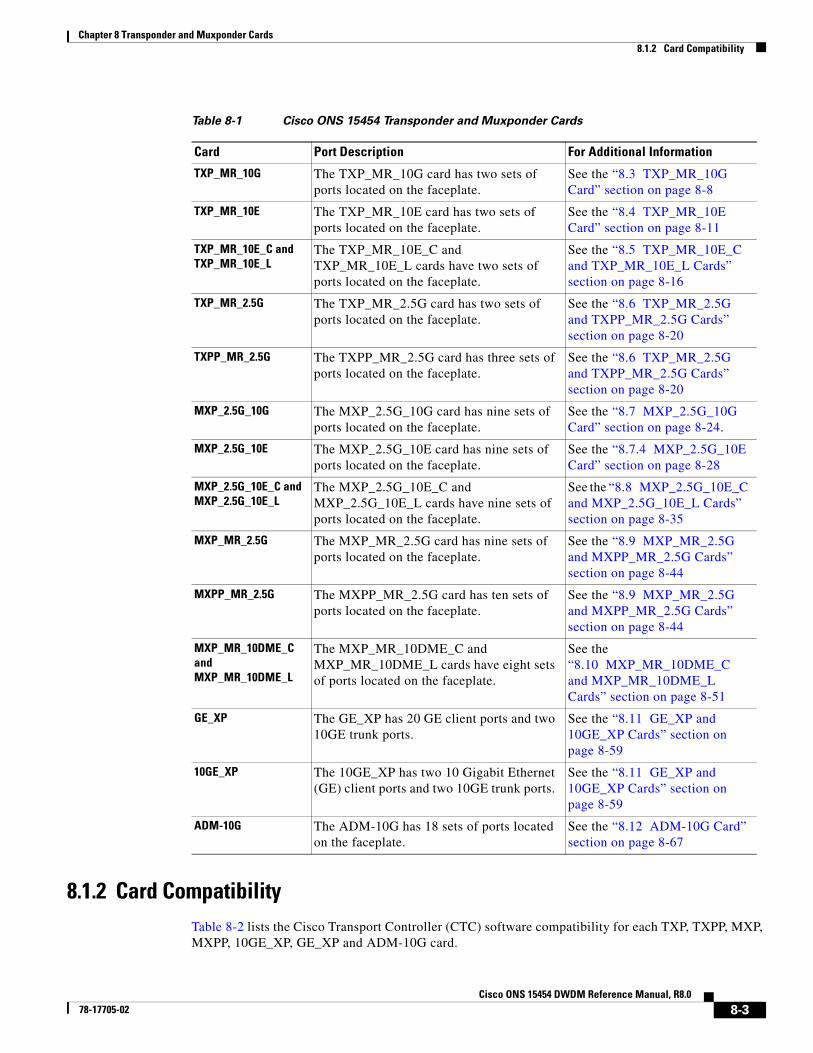
8.1.1 Card SummaryTable 8-1 lists and summarizes the functions of each TXP, TXPP, MXP, and MXPP card.
8-2Cisco ONS 15454 DWDM Reference Manual, R8.0
78-17705-02
Chapter 8 Transponder and Muxponder Cards8.1.2 Card Compatibility
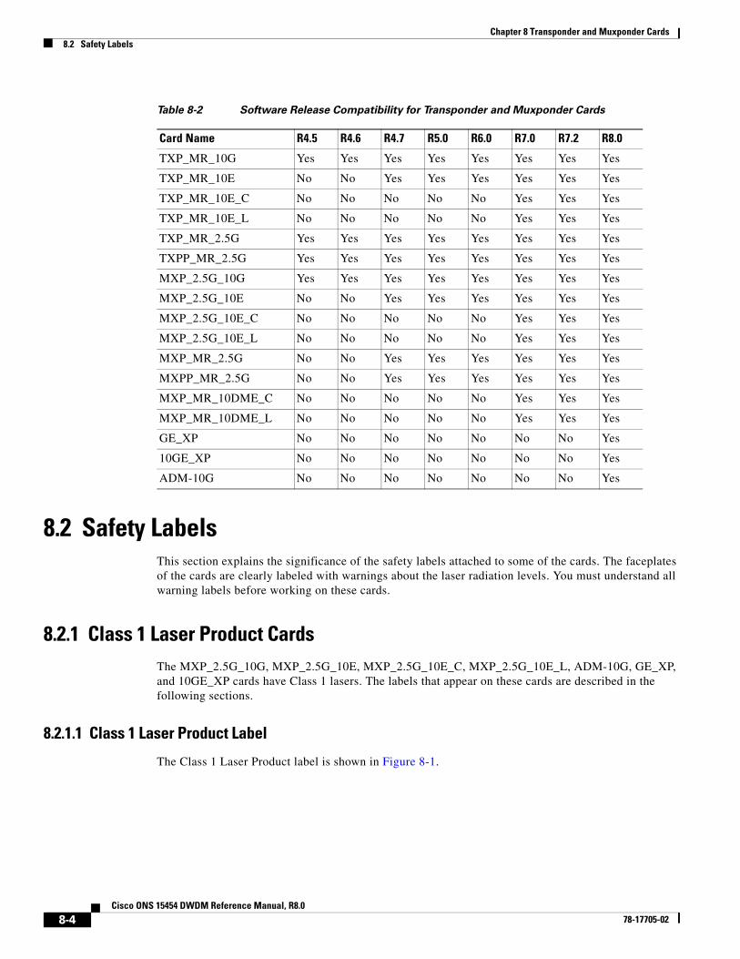
8.1.2 Card CompatibilityTable 8-2 lists the Cisco Transport Controller (CTC) software compatibility for each TXP, TXPP, MXP, MXPP, 10GE_XP, GE_XP and ADM-10G card.
Table 8-1 Cisco ONS 15454 Transponder and Muxponder Cards
Card Port Description For Additional Information
TXP_MR_10G The TXP_MR_10G card has two sets of ports located on the faceplate.
See the “8.3 TXP_MR_10G Card” section on page 8-8
TXP_MR_10E The TXP_MR_10E card has two sets of ports located on the faceplate.
See the “8.4 TXP_MR_10E Card” section on page 8-11
TXP_MR_10E_C and TXP_MR_10E_L
The TXP_MR_10E_C and TXP_MR_10E_L cards have two sets of ports located on the faceplate.
See the “8.5 TXP_MR_10E_C and TXP_MR_10E_L Cards” section on page 8-16
TXP_MR_2.5G The TXP_MR_2.5G card has two sets of ports located on the faceplate.
See the “8.6 TXP_MR_2.5G and TXPP_MR_2.5G Cards” section on page 8-20
TXPP_MR_2.5G The TXPP_MR_2.5G card has three sets of ports located on the faceplate.
See the “8.6 TXP_MR_2.5G and TXPP_MR_2.5G Cards” section on page 8-20
MXP_2.5G_10G The MXP_2.5G_10G card has nine sets of ports located on the faceplate.
See the “8.7 MXP_2.5G_10G Card” section on page 8-24.
MXP_2.5G_10E The MXP_2.5G_10E card has nine sets of ports located on the faceplate.
See the “8.7.4 MXP_2.5G_10E Card” section on page 8-28
MXP_2.5G_10E_C and MXP_2.5G_10E_L
The MXP_2.5G_10E_C and MXP_2.5G_10E_L cards have nine sets of ports located on the faceplate.
See the “8.8 MXP_2.5G_10E_C and MXP_2.5G_10E_L Cards” section on page 8-35
MXP_MR_2.5G The MXP_MR_2.5G card has nine sets of ports located on the faceplate.
See the “8.9 MXP_MR_2.5G and MXPP_MR_2.5G Cards” section on page 8-44
MXPP_MR_2.5G The MXPP_MR_2.5G card has ten sets of ports located on the faceplate.
See the “8.9 MXP_MR_2.5G and MXPP_MR_2.5G Cards” section on page 8-44
MXP_MR_10DME_C and MXP_MR_10DME_L
The MXP_MR_10DME_C and MXP_MR_10DME_L cards have eight sets of ports located on the faceplate.
See the “8.10 MXP_MR_10DME_C and MXP_MR_10DME_L Cards” section on page 8-51
GE_XP The GE_XP has 20 GE client ports and two 10GE trunk ports.
See the “8.11 GE_XP and 10GE_XP Cards” section on page 8-59
10GE_XP The 10GE_XP has two 10 Gigabit Ethernet (GE) client ports and two 10GE trunk ports.
See the “8.11 GE_XP and 10GE_XP Cards” section on page 8-59
ADM-10G The ADM-10G has 18 sets of ports located on the faceplate.
See the “8.12 ADM-10G Card” section on page 8-67
8-3Cisco ONS 15454 DWDM Reference Manual, R8.0
78-17705-02
Chapter 8 Transponder and Muxponder Cards8.2 Safety Labels
8.2 Safety LabelsThis section explains the significance of the safety labels attached to some of the cards. The faceplates of the cards are clearly labeled with warnings about the laser radiation levels. You must understand all warning labels before working on these cards.
8.2.1 Class 1 Laser Product CardsThe MXP_2.5G_10G, MXP_2.5G_10E, MXP_2.5G_10E_C, MXP_2.5G_10E_L, ADM-10G, GE_XP, and 10GE_XP cards have Class 1 lasers. The labels that appear on these cards are described in the following sections.
8.2.1.1 Class 1 Laser Product Label
The Class 1 Laser Product label is shown in Figure 8-1.
Table 8-2 Software Release Compatibility for Transponder and Muxponder Cards
Card Name R4.5 R4.6 R4.7 R5.0 R6.0 R7.0 R7.2 R8.0
TXP_MR_10G Yes Yes Yes Yes Yes Yes Yes Yes
TXP_MR_10E No No Yes Yes Yes Yes Yes Yes
TXP_MR_10E_C No No No No No Yes Yes Yes
TXP_MR_10E_L No No No No No Yes Yes Yes
TXP_MR_2.5G Yes Yes Yes Yes Yes Yes Yes Yes
TXPP_MR_2.5G Yes Yes Yes Yes Yes Yes Yes Yes
MXP_2.5G_10G Yes Yes Yes Yes Yes Yes Yes Yes
MXP_2.5G_10E No No Yes Yes Yes Yes Yes Yes
MXP_2.5G_10E_C No No No No No Yes Yes Yes
MXP_2.5G_10E_L No No No No No Yes Yes Yes
MXP_MR_2.5G No No Yes Yes Yes Yes Yes Yes
MXPP_MR_2.5G No No Yes Yes Yes Yes Yes Yes
MXP_MR_10DME_C No No No No No Yes Yes Yes
MXP_MR_10DME_L No No No No No Yes Yes Yes
GE_XP No No No No No No No Yes
10GE_XP No No No No No No No Yes
ADM-10G No No No No No No No Yes
8-4Cisco ONS 15454 DWDM Reference Manual, R8.0
78-17705-02
Chapter 8 Transponder and Muxponder Cards8.2.1 Class 1 Laser Product Cards
Figure 8-1 Class 1 Laser Product Label
Class 1 lasers are products whose irradiance does not exceed the Maximum Permissible Exposure (MPE) value. Therefore, for Class 1 laser products the output power is below the level at which it is believed eye damage will occur. Exposure to the beam of a Class 1 laser will not result in eye injury and can therefore be considered safe. However, some Class 1 laser products might contain laser systems of a higher Class but there are adequate engineering control measures to ensure that access to the beam is not reasonably likely. Anyone who dismantles a Class 1 laser product that contains a higher Class laser system is potentially at risk of exposure to a hazardous laser beam
8.2.1.2 Hazard Level 1 Label
The Hazard Level 1 label is shown in Figure 8-2.
Figure 8-2 Hazard Level Label
The Hazard Level label warns users against exposure to laser radiation of Class 1 limits calculated in accordance with IEC60825-1 Ed.1.2.
8.2.1.3 Laser Source Connector Label
The Laser Source Connector label is shown in Figure 8-3.
Figure 8-3 Laser Source Connector Label
This label indicates that a laser source is present at the optical connector where the label has been placed.
8.2.1.4 FDA Statement Label
The FDA Statement label is shown in Figure 8-4.
CLASS 1 LASER PRODUCT
1459
52
HAZARDLEVEL 1
6554
2
9663
5
8-5Cisco ONS 15454 DWDM Reference Manual, R8.0
78-17705-02
Chapter 8 Transponder and Muxponder Cards8.2.2 Class 1M Laser Product Cards
Figure 8-4 FDA Statement Label
This label shows compliance to FDA standards and that the hazard level classification is in accordance with IEC60825-1 Am.2 or Ed.1.2.
8.2.1.5 Shock Hazard Label
The Shock Hazard label is shown in Figure 8-5.
Figure 8-5 Shock Hazard Label
This label alerts personnel to electrical hazard within the card. The potential of shock hazard exists when removing adjacent cards during maintenance, and touching exposed electrical circuitry on the card itself.
8.2.2 Class 1M Laser Product CardsThe TXP_MR_10G, TXP_MR_10E, TXP_MR_10E_C, TXP_MR_10E_L, TXP_MR_2.5G, TXPP_MR_2.5G, MXP_MR_2.5G, MXPP_MR_2.5G, MXP_MR_10DME_C, and MXP_MR_10DME_L cards have Class 1M lasers.
The labels that appear on these cards are described in the following subsections.
8.2.2.1 Class 1M Laser Product Label
The Class 1M Laser Product label is shown in Figure 8-6.
9663
4
COMPLIES WITH 21 CFR 1040.10AND 1040.11 EXCEPT FOR
DEVIATIONS PURSUANT TOLASER NOTICE NO.50,DATED JULY 26, 2001
6554
1
8-6Cisco ONS 15454 DWDM Reference Manual, R8.0
78-17705-02
Chapter 8 Transponder and Muxponder Cards8.2.2 Class 1M Laser Product Cards
Figure 8-6 Class 1M Laser Product Label
Class 1M lasers are products that produce either a highly divergent beam or a large diameter beam. Therefore, only a small part of the whole laser beam can enter the eye. However, these laser products can be harmful to the eye if the beam is viewed using magnifying optical instruments.
8.2.2.2 Hazard Level 1M Label
The Hazard Level 1M label is shown in Figure 8-7.
Figure 8-7 Hazard Level Label
The Hazard Level label warns users against exposure to laser radiation of Class 1 limits calculated in accordance with IEC60825-1 Ed.1.2.
8.2.2.3 Laser Source Connector Label
The Laser Source Connector label is shown in Figure 8-8.
Figure 8-8 Laser Source Connector Label
This label indicates that a laser source is present at the optical connector where the label has been placed.
8.2.2.4 FDA Statement Label
The FDA Statement label is shown in Figure 8-9.
CAUTIONHAZARD LEVEL 1M INVISIBLE
LASER RADIATIONDO NOT VIEW DIRECTLY WITHNON-ATTENUATING OPTICAL
INSTRUMENTS λ =λ = 1400nm TO 1610nm
1459
53
HAZARDLEVEL 1M
1459
90
9663
5
8-7Cisco ONS 15454 DWDM Reference Manual, R8.0
78-17705-02
Chapter 8 Transponder and Muxponder Cards8.3 TXP_MR_10G Card
Figure 8-9 FDA Statement Label
This label shows compliance to FDA standards and that the hazard level classification is in accordance with IEC60825-1 Am.2 or Ed.1.2.
8.2.2.5 Shock Hazard Label
The Shock Hazard label is shown in Figure 8-10.
Figure 8-10 Shock Hazard Label
This label alerts personnel to electrical hazard within the card. The potential of shock hazard exists when removing adjacent cards during maintenance, and touching exposed electrical circuitry on the card itself.
8.3 TXP_MR_10G CardThe TXP_MR_10G processes one 10-Gbps signal (client side) into one 10-Gbps, 100-GHz DWDM signal (trunk side). It provides one 10-Gbps port per card that can be provisioned for an STM-64/OC-192 short reach (1310-nm) signal, compliant with ITU-T G.707, ITU-T G.709, ITU-T G.691, and Telcordia GR-253-CORE, or a 10GBASE-LR signal compliant with IEEE 802.3.
The TXP_MR_10G card is tunable over two neighboring wavelengths in the 1550-nm, ITU 100-GHz range. It is available in 16 different versions, each of which covers two wavelengths, for a total coverage of 32 different wavelengths in the 1550-nm range.
Note ITU-T G.709 specifies a form of forward error correction (FEC) that uses a “wrapper” approach. The digital wrapper lets you transparently take in a signal on the client side, wrap a frame around it and restore it to its original form. FEC enables longer fiber links because errors caused by the optical signal degrading with distance are corrected.
9663
4
COMPLIES WITH 21 CFR 1040.10AND 1040.11 EXCEPT FOR
DEVIATIONS PURSUANT TOLASER NOTICE NO.50,DATED JULY 26, 2001
6554
1
8-8Cisco ONS 15454 DWDM Reference Manual, R8.0
78-17705-02
Chapter 8 Transponder and Muxponder Cards8.3 TXP_MR_10G Card
The trunk port operates at 9.95328 Gbps (or 10.70923 Gbps with ITU-T G.709 Digital Wrapper/FEC) and at 10.3125 Gbps (or 11.095 Gbps with ITU-T G.709 Digital Wrapper/FEC) over unamplified distances up to 80 km (50 miles) with different types of fiber such as C-SMF or dispersion compensated fiber limited by loss and/or dispersion.
Caution Because the transponder has no capability to look into the payload and detect circuits, a TXP_MR_10G card does not display circuits under card view.
Caution You must use a 15-dB fiber attenuator (10 to 20 dB) when working with the TXP_MR_10G card in a loopback on the trunk port. Do not use direct fiber loopbacks with the TXP_MR_10G card. Using direct fiber loopbacks causes irreparable damage to the TXP_MR_10G card.
You can install TXP_MR_10G cards in Slots 1 to 6 and 12 to 17 and provision this card in a linear configuration. TXP_MR_10G cards cannot be provisioned as a bidirectional line switched ring (BLSR)/Multiplex Section - Shared Protection Ring (MS-SPRing), path protection/single node control point (SNCP), or a regenerator. They can only be used in the middle of BLSR/MS-SPRing and 1+1 spans when the card is configured for transparent termination mode.
The TXP_MR_10G port features a 1550-nm laser for the trunk port and a 1310-nm laser for the for the client port and contains two transmit and receive connector pairs (labeled) on the card faceplate.
The MTU setting is used to display the OverSizePkts counters on the receiving trunk and client port interfaces. Traffic of frame sizes up to 65535 bytes pass without any packet drops, from the client port to the trunk port and vice versa irrespective of the MTU setting.
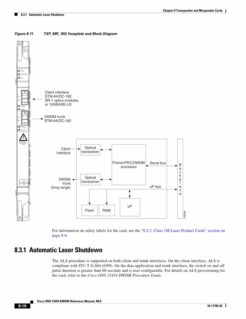
Figure 8-11 shows the TXP_MR_10G faceplate and block diagram.
8-9Cisco ONS 15454 DWDM Reference Manual, R8.0
78-17705-02
Chapter 8 Transponder and Muxponder Cards8.3.1 Automatic Laser Shutdown
Figure 8-11 TXP_MR_10G Faceplate and Block Diagram
For information on safety labels for the card, see the “8.2.2 Class 1M Laser Product Cards” section on page 8-6.
8.3.1 Automatic Laser ShutdownThe ALS procedure is supported on both client and trunk interfaces. On the client interface, ALS is compliant with ITU-T G.664 (6/99). On the data application and trunk interface, the switch on and off pulse duration is greater than 60 seconds and is user-configurable. For details on ALS provisioning for the card, refer to the Cisco ONS 15454 DWDM Procedure Guide.
uP bus
Serial bus
uPFlash RAM
Opticaltransceiver
1459
48
Framer/FEC/DWDMprocessor
Clientinterface
DWDMtrunk
(long range)
Opticaltransceiver
Client interfaceSTM-64/OC-192SR-1 optics modulesor 10GBASE-LR
Backplane
DWDM trunkSTM-64/OC-192
10G MRTXP1530.33 -1531.12
FAIL
ACT/STBY
SF
TX
RX
CLIENT
1530.33
1531.12
DWDM
TX
RX
!!MAX INPUT
POWER LEVEL - 8 dBm
8-10Cisco ONS 15454 DWDM Reference Manual, R8.0
78-17705-02
Chapter 8 Transponder and Muxponder Cards8.3.2 TXP_MR_10G Card-Level Indicators
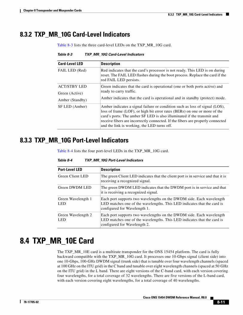
8.3.2 TXP_MR_10G Card-Level IndicatorsTable 8-3 lists the three card-level LEDs on the TXP_MR_10G card.
8.3.3 TXP_MR_10G Port-Level IndicatorsTable 8-4 lists the four port-level LEDs in the TXP_MR_10G card.
8.4 TXP_MR_10E Card The TXP_MR_10E card is a multirate transponder for the ONS 15454 platform. The card is fully backward compatible with the TXP_MR_10G card. It processes one 10-Gbps signal (client side) into one 10-Gbps, 100-GHz DWDM signal (trunk side) that is tunable over four wavelength channels (spaced at 100 GHz on the ITU grid) in the C band and tunable over eight wavelength channels (spaced at 50 GHz on the ITU grid) in the L band. There are eight versions of the C-band card, with each version covering four wavelengths, for a total coverage of 32 wavelengths. There are five versions of the L-band card, with each version covering eight wavelengths, for a total coverage of 40 wavelengths.
Table 8-3 TXP_MR_10G Card-Level Indicators
Card-Level LED Description
FAIL LED (Red) Red indicates that the card’s processor is not ready. This LED is on during reset. The FAIL LED flashes during the boot process. Replace the card if the red FAIL LED persists.
ACT/STBY LED
Green (Active)
Amber (Standby)
Green indicates that the card is operational (one or both ports active) and ready to carry traffic.
Amber indicates that the card is operational and in standby (protect) mode.
SF LED (Amber) Amber indicates a signal failure or condition such as loss of signal (LOS), loss of frame (LOF), or high bit error rates (BERs) on one or more of the card’s ports. The amber SF LED is also illuminated if the transmit and receive fibers are incorrectly connected. If the fibers are properly connected and the link is working, the LED turns off.
Table 8-4 TXP_MR_10G Port-Level Indicators
Port-Level LED Description
Green Client LED The green Client LED indicates that the client port is in service and that it is receiving a recognized signal.
Green DWDM LED The green DWDM LED indicates that the DWDM port is in service and that it is receiving a recognized signal.
Green Wavelength 1 LED
Each port supports two wavelengths on the DWDM side. Each wavelength LED matches one of the wavelengths. This LED indicates that the card is configured for Wavelength 1.
Green Wavelength 2 LED
Each port supports two wavelengths on the DWDM side. Each wavelength LED matches one of the wavelengths. This LED indicates that the card is configured for Wavelength 2.
8-11Cisco ONS 15454 DWDM Reference Manual, R8.0
78-17705-02
Chapter 8 Transponder and Muxponder Cards8.4.1 Key Features
You can install TXP_MR_10E cards in Slots 1 to 6 and 12 to 17 and provision the cards in a linear configuration, BLSR/MS-SPRing, path protection/SNCP, or a regenerator. The card can be used in the middle of BLSR/MS-SPRing or 1+1 spans when the card is configured for transparent termination mode.
The TXP_MR_10E card features a 1550-nm tunable laser (C band) or a 1580-nm tunable laser (L band) for the trunk port and a separately orderable ONS-XC-10G-S1 1310-nm or ONS-XC-10G-L2 1550-nm laser XFP module for the client port.
Note When the ONS-XC-10G-L2 XFP is installed, the TXP_MR_10E card must be installed in Slots 5, 6, 12 or 13.
On its faceplate, the TXP_MR_10E card contains two transmit and receive connector pairs, one for the trunk port and one for the client port. Each connector pair is labeled.
8.4.1 Key Features The key features of the TXP_MR_10E card are:
• A tri-rate client interface (available through the ONS-XC-10G-S1 XFP, ordered separately)
– OC-192 (SR1)
– 10GE (10GBASE-LR)
– 10G-FC (1200-SM-LL-L)
• OC-192 to ITU-T G.709 OTU2 provisionable synchronous and asynchronous mapping
• The MTU setting is used to display the OverSizePkts counters on the receiving trunk and client port interfaces. Traffic of frame sizes up to 65535 bytes pass without any packet drops, from the client port to the trunk port and vice versa irrespective of the MTU setting.
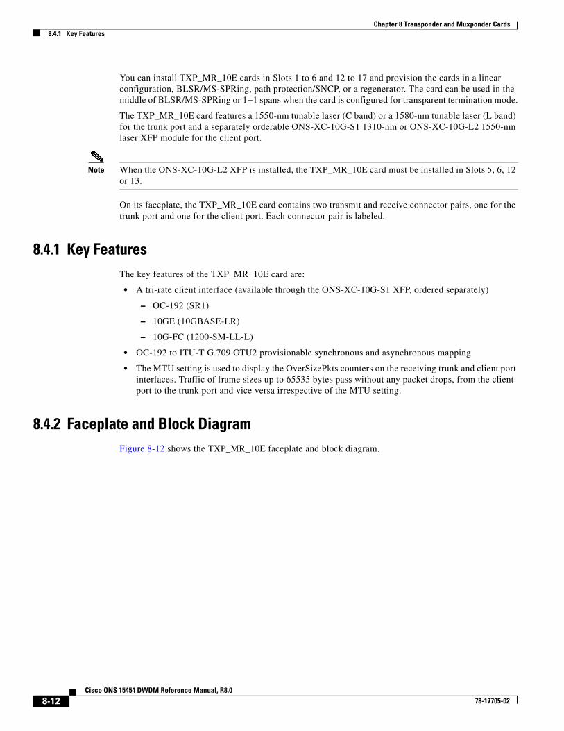
8.4.2 Faceplate and Block DiagramFigure 8-12 shows the TXP_MR_10E faceplate and block diagram.
8-12Cisco ONS 15454 DWDM Reference Manual, R8.0
78-17705-02
Chapter 8 Transponder and Muxponder Cards8.4.3 Client Interface
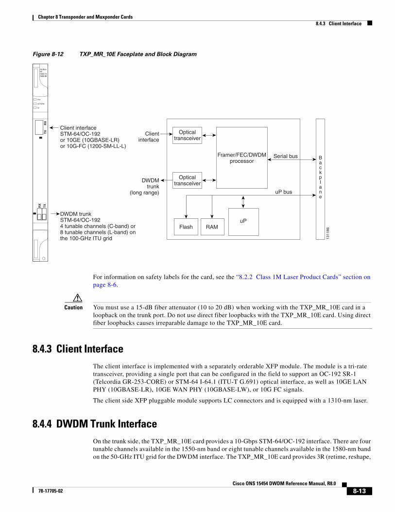
Figure 8-12 TXP_MR_10E Faceplate and Block Diagram
For information on safety labels for the card, see the “8.2.2 Class 1M Laser Product Cards” section on page 8-6.
Caution You must use a 15-dB fiber attenuator (10 to 20 dB) when working with the TXP_MR_10E card in a loopback on the trunk port. Do not use direct fiber loopbacks with the TXP_MR_10E card. Using direct fiber loopbacks causes irreparable damage to the TXP_MR_10E card.
8.4.3 Client InterfaceThe client interface is implemented with a separately orderable XFP module. The module is a tri-rate transceiver, providing a single port that can be configured in the field to support an OC-192 SR-1 (Telcordia GR-253-CORE) or STM-64 I-64.1 (ITU-T G.691) optical interface, as well as 10GE LAN PHY (10GBASE-LR), 10GE WAN PHY (10GBASE-LW), or 10G FC signals.
The client side XFP pluggable module supports LC connectors and is equipped with a 1310-nm laser.
8.4.4 DWDM Trunk InterfaceOn the trunk side, the TXP_MR_10E card provides a 10-Gbps STM-64/OC-192 interface. There are four tunable channels available in the 1550-nm band or eight tunable channels available in the 1580-nm band on the 50-GHz ITU grid for the DWDM interface. The TXP_MR_10E card provides 3R (retime, reshape,
uP bus
Serial bus
uPFlash RAM
Opticaltransceiver
1311
86
Framer/FEC/DWDMprocessor
FAIL
ACT/STBY
SF
10 Gb/sTP1538.191538.98
Clientinterface
DWDMtrunk
(long range)
Opticaltransceiver
Client interfaceSTM-64/OC-192or 10GE (10GBASE-LR)or 10G-FC (1200-SM-LL-L)
Backplane
TX
RX
RX
TX
DWDM trunkSTM-64/OC-1924 tunable channels (C-band) or8 tunable channels (L-band) onthe 100-GHz ITU grid
8-13Cisco ONS 15454 DWDM Reference Manual, R8.0
78-17705-02
Chapter 8 Transponder and Muxponder Cards8.4.5 Enhanced FEC (E-FEC) Feature
and regenerate) transponder functionality for this 10-Gbps trunk interface. Therefore, the card is suited for use in long-range amplified systems. The DWDM interface is complaint with ITU-T G.707, ITU-T G.709, and Telcordia GR-253-CORE standards.
The DWDM trunk port operates at a rate that is dependent on the input signal and the presence or absence of the ITU-T G.709 Digital Wrapper/FEC. The possible trunk rates are:
• OC192 (9.95328 Gbps)
• OTU2 (10.70923 Gbps)
• 10GE (10.3125 Gbps) or 10GE into OTU2 (ITU G.sup43 11.0957 Gbps)
• 10G FC (10.51875 Gbps) or 10G FC into OTU2 (nonstandard 11.31764 Gbps)
The maximum system reach in filterless applications without the use of optical amplification or regenerators is nominally rated at 23 dB over C-SMF fiber. This rating is not a product specification, but is given for informational purposes. It is subject to change.
8.4.5 Enhanced FEC (E-FEC) FeatureA key feature of the TXP_MR_10E is the availability to configure the forward error correction in three modes: NO FEC, FEC, and E-FEC. The output bit rate is always 10.7092 Gbps as defined in ITU-T G.709, but the error coding performance can be provisioned as follows:
• NO FEC—No forward error correction
• FEC—Standard ITU-T G.975 Reed-Solomon algorithm
• E-FEC—Standard ITU-T G.975.1 I.7 algorithm, which is a super FEC code
Note The E-FEC of the ONS 15454 and Cisco ASR 9000 are not compatible.
8.4.6 FEC and E-FEC ModesAs client side traffic passes through the TXP_MR_10E card, it can be digitally wrapped using FEC mode, E-FEC mode, or no error correction at all. The FEC mode setting provides a lower level of error detection and correction than the E-FEC mode setting of the card. As a result, using E-FEC mode allows higher sensitivity (lower optical signal-to-noise ratio [OSNR]) with a lower bit error rate than FEC mode. E-FEC enables longer distance trunk-side transmission than with FEC.
The E-FEC feature is one of three basic modes of FEC operation. FEC can be turned off, FEC can be turned on, or E-FEC can be turned on to provide greater range and lower BER. The default mode is FEC on and E-FEC off. E-FEC is provisioned using CTC.
Caution Because the transponder has no visibility into the data payload and detect circuits, the TXP_MR_10E card does not display circuits under the card view.
8.4.7 Client-to-Trunk MappingThe TXP_MR_10E card can perform ODU2-to-OCh mapping, which allows operators to provision data payloads in a standard way across 10-Gbps optical links.
8-14Cisco ONS 15454 DWDM Reference Manual, R8.0
78-17705-02
Chapter 8 Transponder and Muxponder Cards8.4.8 Automatic Laser Shutdown
Digital wrappers that define client side interfaces are called Optical Data Channel Unit 2 (ODU2) entities in ITU-T G.709. Digital wrappers that define trunk side interfaces are called Optical Channels (OCh) in ITU-T G.709. ODU2 digital wrappers can include Generalized Multiprotocol Label Switching (G-MPLS) signaling extensions to ITU-T G.709 (such as Least Significant Part [LSP] and Generalized Payload Identifier [G-PID] values) to define client interfaces and payload protocols.
8.4.8 Automatic Laser ShutdownThe ALS procedure is supported on both client and trunk interfaces. On the client interface, ALS is compliant with ITU-T G.664 (6/99). On the data application and trunk interface, the switch on and off pulse duration is greater than 60 seconds. The on and off pulse duration is user-configurable. For details on ALS provisioning for the card, refer to the Cisco ONS 15454 DWDM Procedure Guide.
8.4.9 TXP_MR_10E Card-Level IndicatorsTable 8-5 lists the three card-level LEDs on the TXP_MR_10E card.
8.4.10 TXP_MR_10E Port-Level IndicatorsTable 8-6 lists the two port-level LEDs in the TXP_MR_10E card.
Table 8-5 TXP_MR_10E Card-Level Indicators
Card-Level LED Description
Red FAIL LED The red FAIL LED indicates that the card’s processor is not ready. This LED is on during reset. The FAIL LED flashes during the boot process. Replace the card if the red FAIL LED persists.
ACT/STBY LED
Green (Active)
Amber (Standby)
If the ACT/STBY LED is green, the card is operational (one or both ports active) and ready to carry traffic. If the ACT/STBY LED is amber, the card is operational and in standby (protect) mode.
Amber SF LED The amber SF LED indicates a signal failure or condition such as LOS, LOF, or high BERs on one or more of the card’s ports. The amber SF LED is also on if the transmit and receive fibers are incorrectly connected. If the fibers are properly connected and the link is working, the light turns off.
Table 8-6 TXP_MR_10E Port-Level Indicators
Port-Level LED Description
Green Client LED The green Client LED indicates that the client port is in service and that it is receiving a recognized signal.
Green DWDM LED The green DWDM LED indicates that the DWDM port is in service and that it is receiving a recognized signal.
8-15Cisco ONS 15454 DWDM Reference Manual, R8.0
78-17705-02
Chapter 8 Transponder and Muxponder Cards8.5 TXP_MR_10E_C and TXP_MR_10E_L Cards
8.5 TXP_MR_10E_C and TXP_MR_10E_L CardsThe TXP_MR_10E_C and TXP_MR_10E_L cards are multirate transponders for the ONS 15454 platform. The cards are fully backward compatible with the TXP_MR_10G and TXP_MR_10E cards. They processes one 10-Gbps signal (client side) into one 10-Gbps, 100-GHz DWDM signal (trunk side). The TXP_MR_10E_C is tunable over the entire set of C-band wavelength channels (82 channels spaced at 50 GHz on the ITU grid). The TXP_MR_10E_L is tunable over the entire set of L-band wavelength channels (80 channels spaced at 50 GHz on the ITU grid) and is particularly well suited for use in networks that employ DS fiber or SMF-28 single-mode fiber.
The advantage of these cards over previous versions (TXP_MR_10G and TXP_MR_10E) is that there is only one version of each card (one C-band version and one L-band version) instead of several versions needed to cover each band.
You can install TXP_MR_10E_C and TXP_MR_10E_L cards in Slots 1 to 6 and 12 to 17 and provision the cards in a linear configuration, BLSR/MS-SPRing, path protection/SNCP, or a regenerator. The cards can be used in the middle of BLSR/MS-SPRing or 1+1 spans when the cards are configured for transparent termination mode.
The TXP_MR_10E_C and TXP_MR_10E_L cards feature a universal transponder 2 (UT2) 1550-nm tunable laser (C band) or a UT2 1580-nm tunable laser (L band) for the trunk port and a separately orderable ONS-XC-10G-S1 1310-nm or ONS-XC-10G-L2 1550-nm laser XFP module for the client port.
Note When the ONS-XC-10G-L2 XFP is installed, the TXP_MR_10E_C or TXP_MR_10E-L card is required to be installed in a high-speed slot (slot 6, 7, 12, or 13)
On its faceplate, the TXP_MR_10E_C and TXP_MR_10E_L cards contain two transmit and receive connector pairs, one for the trunk port and one for the client port. Each connector pair is labeled.
8.5.1 Key Features The key features of the TXP_MR_10E_C and TXP_MR_10E_L cards are:
• A tri-rate client interface (available through the ONS-XC-10G-S1 XFP, ordered separately):
– OC-192 (SR1)
– 10GE (10GBASE-LR)
– 10G-FC (1200-SM-LL-L)
• A UT2 module tunable through the entire C band (TXP_MR_10E_C card) or L band (TXP_MR_10E_L card). The channels are spaced at 50 GHz on the ITU grid.
• OC-192 to ITU-T G.709 OTU2 provisionable synchronous and asynchronous mapping.
• The MTU setting is used to display the OverSizePkts counters on the receiving trunk and client port interfaces. Traffic of frame sizes up to 65535 bytes pass without any packet drops, from the client port to the trunk port and vice versa irrespective of the MTU setting.
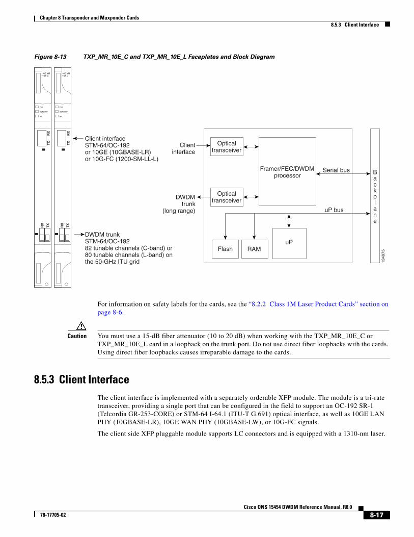
8.5.2 Faceplates and Block DiagramFigure 8-13 shows the TXP_MR_10E_C and TXP_MR_10E_L faceplates and block diagram.
8-16Cisco ONS 15454 DWDM Reference Manual, R8.0
78-17705-02
Chapter 8 Transponder and Muxponder Cards8.5.3 Client Interface
Figure 8-13 TXP_MR_10E_C and TXP_MR_10E_L Faceplates and Block Diagram
For information on safety labels for the cards, see the “8.2.2 Class 1M Laser Product Cards” section on page 8-6.
Caution You must use a 15-dB fiber attenuator (10 to 20 dB) when working with the TXP_MR_10E_C or TXP_MR_10E_L card in a loopback on the trunk port. Do not use direct fiber loopbacks with the cards. Using direct fiber loopbacks causes irreparable damage to the cards.
8.5.3 Client InterfaceThe client interface is implemented with a separately orderable XFP module. The module is a tri-rate transceiver, providing a single port that can be configured in the field to support an OC-192 SR-1 (Telcordia GR-253-CORE) or STM-64 I-64.1 (ITU-T G.691) optical interface, as well as 10GE LAN PHY (10GBASE-LR), 10GE WAN PHY (10GBASE-LW), or 10G-FC signals.
The client side XFP pluggable module supports LC connectors and is equipped with a 1310-nm laser.
uP bus
Serial bus
uPFlash RAM
Opticaltransceiver
1349
75
Framer/FEC/DWDMprocessor
Clientinterface
DWDMtrunk
(long range)
Opticaltransceiver
Client interfaceSTM-64/OC-192or 10GE (10GBASE-LR)or 10G-FC (1200-SM-LL-L)
Backplane
DWDM trunkSTM-64/OC-19282 tunable channels (C-band) or80 tunable channels (L-band) onthe 50-GHz ITU grid
FAIL
ACT/STBY
SF
10E MRTXP L
TX
RX
RX
TX
FAIL
ACT/STBY
SF
10E MRTXP C
TX
RX
RX
TX
8-17Cisco ONS 15454 DWDM Reference Manual, R8.0
78-17705-02
Chapter 8 Transponder and Muxponder Cards8.5.4 DWDM Trunk Interface
8.5.4 DWDM Trunk Interface On the trunk side, the TXP_MR_10E_C and TXP_MR_10E_L cards provide a 10-Gbps STM-64/OC-192 interface. There are 80 tunable channels available in the 1550-nm C band or 82 tunable channels available in the 1580-nm L band on the 50-GHz ITU grid for the DWDM interface. The TXP_MR_10E_C and TXP_MR_10E_C cards provide 3R transponder functionality for this 10-Gbps trunk interface. Therefore, the card is suited for use in long-range amplified systems. The DWDM interface is compliant with ITU-T G.707, ITU-T G.709, and Telcordia GR-253-CORE standards.
The DWDM trunk port operates at a rate that is dependent on the input signal and the presence or absence of the ITU-T G.709 Digital Wrapper/FEC. The possible trunk rates are:
• OC192 (9.95328 Gbps)
• OTU2 (10.70923 Gbps)
• 10GE (10.3125 Gbps) or 10GE into OTU2 (ITU G.sup43 11.0957 Gbps)
• 10G-FC (10.51875 Gbps) or 10G-FC into OTU2 (nonstandard 11.31764 Gbps)
The maximum system reach in filterless applications without the use of optical amplification or regenerators is nominally rated at 23 dB over C-SMF fiber. This rating is not a product specification, but is given for informational purposes. It is subject to change.
8.5.5 Enhanced FEC (E-FEC) FeatureA key feature of the TXP_MR_10E_C and TXP_MR_10E_L cards is the availability to configure the forward error correction in three modes: NO FEC, FEC, and E-FEC. The output bit rate is always 10.7092 Gbps as defined in ITU-T G.709, but the error coding performance can be provisioned as follows:
• NO FEC—No forward error correction
• FEC—Standard ITU-T G.975 Reed-Solomon algorithm
• E-FEC—Standard ITU-T G.975.1 I.7 algorithm, which is a super FEC code
8.5.6 FEC and E-FEC ModesAs client side traffic passes through the TXP_MR_10E_C and TXP_MR_10E_L cards, it can be digitally wrapped using FEC mode, E-FEC mode, or no error correction at all. The FEC mode setting provides a lower level of error detection and correction than the E-FEC mode setting of the card. As a result, using E-FEC mode allows higher sensitivity (lower OSNR) with a lower bit error rate than FEC mode. E-FEC enables longer distance trunk-side transmission than with FEC.
The E-FEC feature is one of three basic modes of FEC operation. FEC can be turned off, FEC can be turned on, or E-FEC can be turned on to provide greater range and lower BER. The default mode is FEC on and E-FEC off. E-FEC is provisioned using CTC.
Caution Because the transponder has no visibility into the data payload and detect circuits, the TXP_MR_10E_C and TXP_MR_10E_L cards do not display circuits under the card view.
8-18Cisco ONS 15454 DWDM Reference Manual, R8.0
78-17705-02
Chapter 8 Transponder and Muxponder Cards8.5.7 Client-to-Trunk Mapping
8.5.7 Client-to-Trunk MappingThe TXP_MR_10E_C and TXP_MR_10E_L cards can perform ODU2-to-OCh mapping, which allows operators to provision data payloads in a standard way across 10-Gbps optical links.
Digital wrappers that define client side interfaces are called ODU2 entities in ITU-T G.709. Digital wrappers that define trunk side interfaces are called OCh in ITU-T G.709. ODU2 digital wrappers can include G-MPLS signaling extensions to ITU-T G.709 (such as LSP and G-PID values) to define client interfaces and payload protocols.
8.5.8 Automatic Laser ShutdownThe ALS procedure is supported on both client and trunk interfaces. On the client interface, ALS is compliant with ITU-T G.664 (6/99). On the data application and trunk interface, the switch on and off pulse duration is greater than 60 seconds. The on and off pulse duration is user-configurable. For details regarding ALS provisioning for the TXP_MR_10E_C and TXP_MR_10E_L cards, refer to the Cisco ONS 15454 DWDM Procedure Guide.
8.5.9 TXP_MR_10E_C and TXP_MR_10E_L Card-Level IndicatorsTable 8-7 lists the three card-level LEDs on the TXP_MR_10E_C and TXP_MR_10E_L cards.
8.5.10 TXP_MR_10E_C and TXP_MR_10E_L Port-Level IndicatorsTable 8-8 lists the two port-level LEDs in the TXP_MR_10E_C and TXP_MR_10E_L cards.
Table 8-7 TXP_MR_10E _C and TXP_MR_10E_L Card-Level Indicators
Card-Level LED Description
Red FAIL LED The red FAIL LED indicates that the card’s processor is not ready. This LED is on during reset. The FAIL LED flashes during the boot process. Replace the card if the red FAIL LED persists.
ACT/STBY LED
Green (Active)
Amber (Standby)
If the ACT/STBY LED is green, the card is operational (one or both ports active) and ready to carry traffic. If the ACT/STBY LED is amber, the card is operational and in standby (protect) mode.
Amber SF LED The amber SF LED indicates a signal failure or condition such as LOS, LOF, or high BERs on one or more of the card’s ports. The amber SF LED is also on if the transmit and receive fibers are incorrectly connected. If the fibers are properly connected and the link is working, the light turns off.
Table 8-8 TXP_MR_10E_C and TXP_MR_10E_L Port-Level Indicators
Port-Level LED Description
Green Client LED The green Client LED indicates that the client port is in service and that it is receiving a recognized signal.
Green DWDM LED The green DWDM LED indicates that the DWDM port is in service and that it is receiving a recognized signal.
8-19Cisco ONS 15454 DWDM Reference Manual, R8.0
78-17705-02
Chapter 8 Transponder and Muxponder Cards8.6 TXP_MR_2.5G and TXPP_MR_2.5G Cards
8.6 TXP_MR_2.5G and TXPP_MR_2.5G CardsThe TXP_MR_2.5G card processes one 8-Mbps to 2.488-Gbps signal (client side) into one 8-Mbps to 2.5-Gbps, 100-GHz DWDM signal (trunk side). It provides one long-reach STM-16/OC-48 port per card, compliant with ITU-T G.707, ITU-T G.709, ITU-T G.957, and Telcordia GR-253-CORE.
The TXPP_MR_2.5G card processes one 8-Mbps to 2.488-Gbps signal (client side) into two 8-Mbps to 2.5-Gbps, 100-GHz DWDM signals (trunk side). It provides two long-reach STM-16/OC-48 ports per card, compliant with ITU-T G.707, ITU-T G.957, and Telcordia GR-253-CORE.
The TXP_MR_2.5G and TXPP_MR_2.5G cards are tunable over four wavelengths in the 1550-nm, ITU 100-GHz range. They are available in eight versions, each of which covers four wavelengths, for a total coverage of 32 different wavelengths in the 1550-nm range.
Note ITU-T G.709 specifies a form of FEC that uses a “wrapper” approach. The digital wrapper lets you transparently take in a signal on the client side, wrap a frame around it, and restore it to its original form. FEC enables longer fiber links because errors caused by the optical signal degrading with distance are corrected.
The trunk/line port operates at up to 2.488 Gbps (or up to 2.66 Gbps with ITU-T G.709 Digital Wrapper/FEC) over unamplified distances up to 360 km (223.7 miles) with different types of fiber such as C-SMF or higher if dispersion compensation is used.
Caution Because the transponder has no capability to look into the payload and detect circuits, a TXP_MR_2.5G or TXPP_MR_2.5G card does not display circuits under card view.
The TXP_MR_2.5G and TXPP_MR_2.5G cards support 2R (retime, regenerate) and 3R (retime, reshape, and regenerate) modes of operation where the client signal is mapped into a ITU-T G.709 frame. The mapping function is simply done by placing a digital wrapper around the client signal. Only OC-48/STM-16 client signals are fully ITU-T G.709 compliant, and the output bit rate depends on the input client signal. Table 8-9 shows the possible combinations of client interfaces, input bit rates, 2R and 3R modes, and ITU-T G.709 monitoring.
Table 8-9 2R and 3R Mode and ITU-T G.709 Compliance by Client Interface
Client Interface Input Bit Rate 3R vs. 2R ITU-T G.709
OC-48/STM-16 2.488 Gbps 3R On or Off
DV-6000 2.38 Gbps 2R —
2 Gigabit Fibre Channel (2G-FC)/fiber connectivity (FICON)
2.125 Gbps 3R1 On or Off
High-Definition Television (HDTV) 1.48 Gbps 2R —
Gigabit Ethernet (GE) 1.25 Gbps 3R On or Off
1 Gigabit Fibre Channel (1G-FC)/FICON 1.06 Gbps 3R On or Off
OC-12/STM-4 622 Mbps 3R On or Off
OC-3/STM-1 155 Mbps 3R On or Off
Enterprise System Connection (ESCON) 200 Mbps 2R —
SDI/D1 video 270 Mbps 2R —
8-20Cisco ONS 15454 DWDM Reference Manual, R8.0
78-17705-02
Chapter 8 Transponder and Muxponder Cards8.6.1 Faceplate
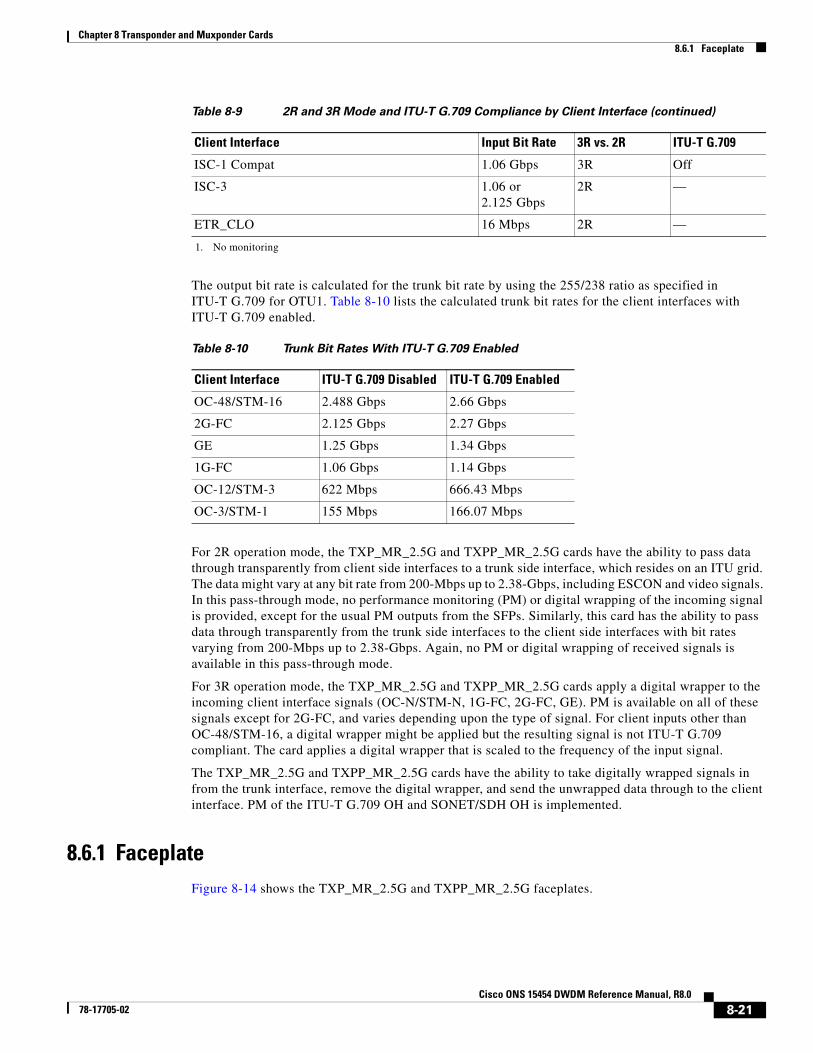
The output bit rate is calculated for the trunk bit rate by using the 255/238 ratio as specified in ITU-T G.709 for OTU1. Table 8-10 lists the calculated trunk bit rates for the client interfaces with ITU-T G.709 enabled.
For 2R operation mode, the TXP_MR_2.5G and TXPP_MR_2.5G cards have the ability to pass data through transparently from client side interfaces to a trunk side interface, which resides on an ITU grid. The data might vary at any bit rate from 200-Mbps up to 2.38-Gbps, including ESCON and video signals. In this pass-through mode, no performance monitoring (PM) or digital wrapping of the incoming signal is provided, except for the usual PM outputs from the SFPs. Similarly, this card has the ability to pass data through transparently from the trunk side interfaces to the client side interfaces with bit rates varying from 200-Mbps up to 2.38-Gbps. Again, no PM or digital wrapping of received signals is available in this pass-through mode.
For 3R operation mode, the TXP_MR_2.5G and TXPP_MR_2.5G cards apply a digital wrapper to the incoming client interface signals (OC-N/STM-N, 1G-FC, 2G-FC, GE). PM is available on all of these signals except for 2G-FC, and varies depending upon the type of signal. For client inputs other than OC-48/STM-16, a digital wrapper might be applied but the resulting signal is not ITU-T G.709 compliant. The card applies a digital wrapper that is scaled to the frequency of the input signal.
The TXP_MR_2.5G and TXPP_MR_2.5G cards have the ability to take digitally wrapped signals in from the trunk interface, remove the digital wrapper, and send the unwrapped data through to the client interface. PM of the ITU-T G.709 OH and SONET/SDH OH is implemented.
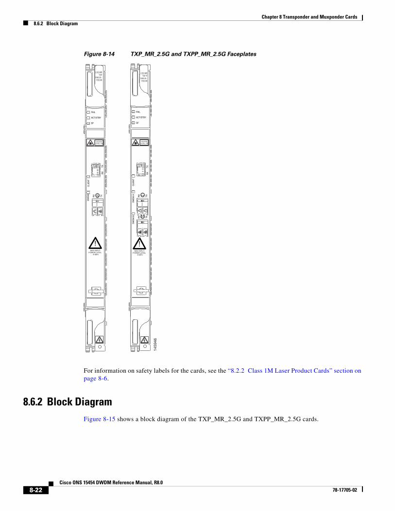
8.6.1 FaceplateFigure 8-14 shows the TXP_MR_2.5G and TXPP_MR_2.5G faceplates.
ISC-1 Compat 1.06 Gbps 3R Off
ISC-3 1.06 or 2.125 Gbps
2R —
ETR_CLO 16 Mbps 2R —
1. No monitoring
Table 8-9 2R and 3R Mode and ITU-T G.709 Compliance by Client Interface (continued)
Client Interface Input Bit Rate 3R vs. 2R ITU-T G.709
Table 8-10 Trunk Bit Rates With ITU-T G.709 Enabled
Client Interface ITU-T G.709 Disabled ITU-T G.709 Enabled
OC-48/STM-16 2.488 Gbps 2.66 Gbps
2G-FC 2.125 Gbps 2.27 Gbps
GE 1.25 Gbps 1.34 Gbps
1G-FC 1.06 Gbps 1.14 Gbps
OC-12/STM-3 622 Mbps 666.43 Mbps
OC-3/STM-1 155 Mbps 166.07 Mbps
8-21Cisco ONS 15454 DWDM Reference Manual, R8.0
78-17705-02
Chapter 8 Transponder and Muxponder Cards8.6.2 Block Diagram
Figure 8-14 TXP_MR_2.5G and TXPP_MR_2.5G Faceplates
For information on safety labels for the cards, see the “8.2.2 Class 1M Laser Product Cards” section on page 8-6.
8.6.2 Block DiagramFigure 8-15 shows a block diagram of the TXP_MR_2.5G and TXPP_MR_2.5G cards.
CLI
EN
T
2.5G MRTXP-P
1530.33 -1532.68
2.5G MRTXP
1530.33 -1532.68
FAIL
ACT/STBY
SF
HAZARDLEVEL 1M
TXR
X
DW
DM
A TXRX
DW
DM
B TXRX
!MAX INPUT
POWER LEVEL - 8 dBm
CLI
EN
T
!MAX INPUT
POWER LEVEL - 8 dBm
FAIL
ACT/STBY
SF
HAZARDLEVEL 1M
TXR
XTXR
X
DW
DM
1459
46
8-22Cisco ONS 15454 DWDM Reference Manual, R8.0
78-17705-02

Chapter 8 Transponder and Muxponder Cards8.6.3 Automatic Laser Shutdown
Figure 8-15 TXP_MR_2.5G and TXPP_MR_2.5G Block Diagram
Caution You must use a 20-dB fiber attenuator (15 to 25 dB) when working with the TXP_MR_2.5G and TXPP_MR_2.5G cards in a loopback on the trunk port. Do not use direct fiber loopbacks with the TXP_MR_2.5G and TXPP_MR_2.5G cards. Using direct fiber loopbacks causes irreparable damage to the TXP_MR_2.5G and TXPP_MR_2.5G cards.
You can install TXP_MR_2.5G and TXPP_MR_2.5G cards in Slots 1 to 6 and 12 to 17. You can provision this card in a linear configuration. TXP_MR_10G and TXPP_MR_2.5G cards cannot be provisioned as a BLSR/MS-SPRing, a path protection/SNCP, or a regenerator. They can be used in the middle of BLSR/MS-SPRing or 1+1 spans only when the card is configured for transparent termination mode.
The TXP_MR_2.5G card features a 1550-nm laser for the trunk/line port and a 1310-nm laser for the client port. It contains two transmit and receive connector pairs (labeled) on the card faceplate. The card uses dual LC connectors for optical cable termination.
The TXPP_MR_2.5G card features a 1550-nm laser for the trunk/line port and a 1310-nm or 850-nm laser (depending on the SFP) for the client port and contains three transmit and receive connector pairs (labeled) on the card faceplate. The card uses dual LC connectors for optical cable termination.
8.6.3 Automatic Laser ShutdownThe ALS procedure is supported on both client and trunk interfaces. On the client interface, ALS is compliant with ITU-T G.664 (6/99). On the data application and trunk interface, the switch on and off pulse duration is greater than 60 seconds. The on and off pulse duration is user-configurable. For details regarding ALS provisioning for the TXP_MR_2.5G and TXPP_MR_2.5G cards, refer to the Cisco ONS 15454 DWDM Procedure Guide.
SFP Client SwitchSwitch Driver
TunableLaser
Switch CrossSwitch
LimitingAmp
LimitingAmp
MainAPD+TA
ProtectAPD+TA
MuxDemux Mux
Demux
MuxDemux
CPU
Main
ASIC
Protect
ASICFPGA
SCLFPGA
SCL BUS
2R Tx pathTrunkOut
2R Rx path
CELL BUS
CPUI/F
CELLBUS DCC
CPU toGCC
9663
6
8-23Cisco ONS 15454 DWDM Reference Manual, R8.0
78-17705-02
Chapter 8 Transponder and Muxponder Cards8.6.4 TXP_MR_2.5G and TXPP_MR_2.5G Card-Level Indicators
8.6.4 TXP_MR_2.5G and TXPP_MR_2.5G Card-Level IndicatorsTable 8-11 lists the three card-level LEDs on the TXP_MR_2.5G and TXPP_MR_2.5G cards.
8.6.5 TXP_MR_2.5G and TXPP_MR_2.5G Port-Level IndicatorsTable 8-12 lists the four port-level LEDs on the TXP_MR_2.5G and TXPP_MR_2.5G cards.
8.7 MXP_2.5G_10G CardThe MXP_2.5G_10G card multiplexes/demultiplexes four 2.5-Gbps signals (client side) into one 10-Gbps, 100-GHz DWDM signal (trunk side). It provides one extended long-range STM-64/OC-192 port per card on the trunk side (compliant with ITU-T G.707, ITU-T G.709, ITU-T G.957, and Telcordia GR-253-CORE) and four intermediate- or short-range OC-48/STM-16 ports per card on the client side. The port operates at 9.95328 Gbps over unamplified distances up to 80 km (50 miles) with different types of fiber such as C-SMF or dispersion compensated fiber limited by loss and/or dispersion.
Client ports on the MXP_2.5G_10G card are also interoperable with SONET OC-1 (STS-1) fiber optic signals defined in Telcordia GR-253-CORE. An OC-1 signal is the equivalent of one DS-3 channel transmitted across optical fiber. OC-1 is primarily used for trunk interfaces to phone switches in the United States. There is no SDH equivalent for SONET OC-1.
Table 8-11 TXP_MR_2.5G and TXPP_MR_2.5G Card-Level Indicators
Card-Level LED Description
Red FAIL LED The red FAIL LED indicates that the card’s processor is not ready. This LED is on during reset. The FAIL LED flashes during the boot process. Replace the card if the red FAIL LED persists.
ACT/STBY LED
Green (Active)
Amber (Standby)
If the ACT/STBY LED is green, the card is operational (one or both ports active) and ready to carry traffic. If the ACT/STBY LED is amber, the card is operational and in standby (protect) mode.
Amber SF LED The amber SF LED indicates a signal failure or condition such as LOS, LOF, or high BERs on one or more of the card’s ports. The amber SF LED is also on if the transmit and receive fibers are incorrectly connected. If the fibers are properly connected and the link is working, the light turns off.
Table 8-12 TXP_MR_2.5G and TXPP_MR_2.5G Port-Level Indicators
Port-Level LED Description
Green Client LED The green Client LED indicates that the client port is in service and that it is receiving a recognized signal.
Green DWDM LED(TXP_MR_2.5G only)
The green DWDM LED indicates that the DWDM port is in service and that it is receiving a recognized signal.
Green DWDM A LED(TXPP_MR_2.5G only)
The green DWDM A LED indicates that the DWDM A port is in service and that it is receiving a recognized signal.
Green DWDM B LED(TXPP_MR_2.5G only)
The green DWDM B LED indicates that the DWDM B port is in service and that it is receiving a recognized signal.
8-24Cisco ONS 15454 DWDM Reference Manual, R8.0
78-17705-02
Chapter 8 Transponder and Muxponder Cards8.7 MXP_2.5G_10G Card
The MXP_2.5G_10G card is tunable over two neighboring wavelengths in the 1550-nm, ITU 100-GHz range. It is available in 16 different versions, each of which covers two wavelengths, for a total coverage of 32 different wavelengths in the 1550-nm range.
Note ITU-T G.709 specifies a form of FEC that uses a “wrapper” approach. The digital wrapper lets you transparently take in a signal on the client side, wrap a frame around it and restore it to its original form. FEC enables longer fiber links because errors caused by the optical signal degrading with distance are corrected.
The port can also operate at 10.70923 Gbps in ITU-T G.709 Digital Wrapper/FEC mode.
Caution Because the transponder has no capability to look into the payload and detect circuits, an MXP_2.5G_10G card does not display circuits under card view.
Caution You must use a 20-dB fiber attenuator (15 to 25 dB) when working with the MXP_2.5G_10G card in a loopback on the trunk port. Do not use direct fiber loopbacks with the MXP_2.5G_10G card. Using direct fiber loopbacks causes irreparable damage to the MXP_2.5G_10G card.
You can install MXP_2.5G_10G cards in Slots 1 to 6 and 12 to 17.
Caution Do not install an MXP_2.5G_10G card in Slot 3 if you have installed a DS3/EC1-48 card in Slots 1or 2. Likewise, do not install an MXP_2.5G_10G card in Slot 17 if you have installed a DS3/EC1-48 card in Slots 15 or 16. If you do, the cards will interact and cause DS-3 bit errors.
You can provision this card in a linear configuration. MXP_2.5G_10G cards cannot be provisioned as a BLSR/MS-SPRing, a path protection/SNCP, or a regenerator. They can be used in the middle of BLSR/MS-SPRing or 1+1 spans only when the card is configured for transparent termination mode.
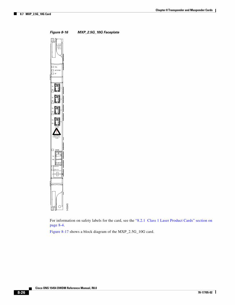
The MXP_2.5G_10G port features a 1550-nm laser on the trunk port and four 1310-nm lasers on the client ports and contains five transmit and receive connector pairs (labeled) on the card faceplate. The card uses a dual LC connector on the trunk side and SFP connectors on the client side for optical cable termination.
Note When you create a 4xOC-48 OCHCC circuit, you need to select the G.709 and Synchronous options. A 4xOC-48 OCHCC circuit is supported by G.709 and synchronous mode. This is necessary to provision a 4xOC-48 OCHCC circuit.
Figure 8-16 shows the MXP_2.5G_10G faceplate.
8-25Cisco ONS 15454 DWDM Reference Manual, R8.0
78-17705-02
Chapter 8 Transponder and Muxponder Cards8.7 MXP_2.5G_10G Card
Figure 8-16 MXP_2.5G_10G Faceplate
For information on safety labels for the card, see the “8.2.1 Class 1 Laser Product Cards” section on page 8-4.
Figure 8-17 shows a block diagram of the MXP_2.5G_10G card.
CLIENT
DWDM
1
2
4x 2.5G10G MXP1530.33 -
1531.12
FAIL
ACT/STBY
SF
TX
RX
TX
RX
3TX
RX
4TX
RX
!MAX INPUT
POWER LEVEL - 8 dBm
TX
RX
1530.33
1531.12
1459
45
8-26Cisco ONS 15454 DWDM Reference Manual, R8.0
78-17705-02
Chapter 8 Transponder and Muxponder Cards8.7.1 Timing Synchronization
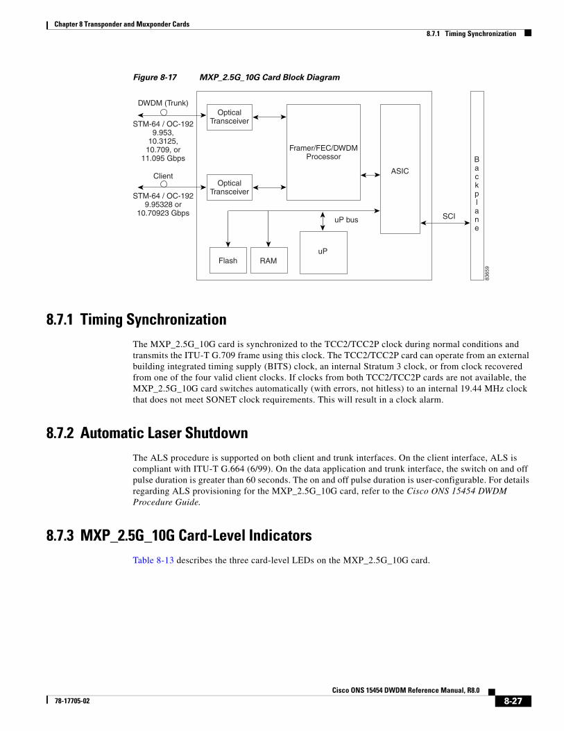
Figure 8-17 MXP_2.5G_10G Card Block Diagram
8.7.1 Timing SynchronizationThe MXP_2.5G_10G card is synchronized to the TCC2/TCC2P clock during normal conditions and transmits the ITU-T G.709 frame using this clock. The TCC2/TCC2P card can operate from an external building integrated timing supply (BITS) clock, an internal Stratum 3 clock, or from clock recovered from one of the four valid client clocks. If clocks from both TCC2/TCC2P cards are not available, the MXP_2.5G_10G card switches automatically (with errors, not hitless) to an internal 19.44 MHz clock that does not meet SONET clock requirements. This will result in a clock alarm.
8.7.2 Automatic Laser ShutdownThe ALS procedure is supported on both client and trunk interfaces. On the client interface, ALS is compliant with ITU-T G.664 (6/99). On the data application and trunk interface, the switch on and off pulse duration is greater than 60 seconds. The on and off pulse duration is user-configurable. For details regarding ALS provisioning for the MXP_2.5G_10G card, refer to the Cisco ONS 15454 DWDM Procedure Guide.
8.7.3 MXP_2.5G_10G Card-Level IndicatorsTable 8-13 describes the three card-level LEDs on the MXP_2.5G_10G card.
uP bus
uPFlash RAM
ASIC
OpticalTransceiverSTM-64 / OC-192
9.953,10.3125,
10.709, or11.095 Gbps
SCI
8365
9
Backplane
OpticalTransceiverSTM-64 / OC-192
9.95328 or10.70923 Gbps
Framer/FEC/DWDMProcessor
DWDM (Trunk)
Client
8-27Cisco ONS 15454 DWDM Reference Manual, R8.0
78-17705-02
Chapter 8 Transponder and Muxponder Cards8.7.4 MXP_2.5G_10E Card
8.7.3.1 MXP_2.5G_10G Port-Level Indicators
Table 8-14 describes the four port-level LEDs on the MXP_2.5G_10G card.
8.7.4 MXP_2.5G_10E Card The faceplate designation of the card is “4x2.5G 10E MXP.” The MXP_2.5G_10E card is a DWDM muxponder for the ONS 15454 platform that supports full transparent termination the client side. The card multiplexes four 2.5 Gbps client signals (4 x OC48/STM-16 SFP) into a single 10-Gbps DWDM optical signal on the trunk side. The MXP_2.5G_10E provides wavelength transmission service for the four incoming 2.5 Gbps client interfaces. The MXP_2.5G_10E muxponder passes all SONET/SDH overhead bytes transparently.
The digital wrapper function (ITU-T G.709 compliant) formats the DWDM wavelength so that it can be used to set up generic communications channels (GCCs) for data communications, enable FEC, or facilitate performance monitoring.
Table 8-13 MXP_2.5G_10G Card-Level Indicators
Card-Level LED Description
Red FAIL LED The red FAIL LED indicates that the card’s processor is not ready. This LED is on during reset. The FAIL LED flashes during the boot process. Replace the card if the red FAIL LED persists.
ACT/STBY LED
Green (Active)
Amber (Standby)
If the ACT/STBY LED is green, the card is operational (one or more ports active) and ready to carry traffic. If the ACT/STBY LED is amber, the card is operational and in standby (protect) mode.
Amber SF LED The amber SF LED indicates a signal failure or condition such as LOS, LOF, or high BERs on one or more of the card’s ports. The amber SF LED is also on if the transmit and receive fibers are incorrectly connected. If the fibers are properly connected and the link is working, the light turns off.
Table 8-14 MXP_2.5G_10G Port-Level Indicators
Port-Level LED Description
Green Client LED(four LEDs)
The green Client LED indicates that the client port is in service and that it is receiving a recognized signal. The card has four client ports, and so has four Client LEDs.
Green DWDM LED The green DWDM LED indicates that the DWDM port is in service and that it is receiving a recognized signal.
Green Wavelength 1 LED
Each port supports two wavelengths on the DWDM side. Each wavelength LED matches one of the wavelengths. This LED indicates that the card is configured for Wavelength 1.
Green Wavelength 2 LED
Each port supports two wavelengths on the DWDM side. Each wavelength LED matches one of the wavelengths. This LED indicates that the card is configured for Wavelength 2.
8-28Cisco ONS 15454 DWDM Reference Manual, R8.0
78-17705-02
Chapter 8 Transponder and Muxponder Cards8.7.4 MXP_2.5G_10E Card
The MXP_2.5G_10E works with optical transport network (OTN) devices defined in ITU-T G.709. The card supports ODU1 to OTU2 multiplexing, an industry standard method for asynchronously mapping a SONET/SDH payload into a digitally wrapped envelope. See the “8.7.7 Multiplexing Function” section on page 8-31.
The MXP_2.5G_10E card is not compatible with the MXP_2.5G_10G card, which does not support full transparent termination. You can install MXP_2.5G_10E cards in Slots 1 to 6 and 12 to 17. You can provision this card in a linear configuration, as a BLSR/MS-SPRing, a path protection/SNCP, or a regenerator. The card can be used in the middle of BLSR/MS-SPRing or 1+1 spans when the card is configured for transparent termination mode.
The MXP_2.5G_10E features a 1550-nm laser on the trunk port and four 1310-nm lasers on the client ports and contains five transmit and receive connector pairs (labeled) on the card faceplate. The card uses a dual LC connector on the trunk side and uses SFP modules on the client side for optical cable termination. The SFP pluggable modules are short reach (SR) or intermediate reach (IR) and support an LC fiber connector.
Note When you create a 4xOC-48 OCHCC circuit, you need to select the G.709 and Synchronous options. A 4xOC-48 OCHCC circuit is supported by G.709 and synchronous mode. This is necessary to provision a 4xOC-48 OCHCC circuit.
8.7.4.1 Key Features
The MXP_2.5G_10E card has the following high level features:
• Four 2.5 Gbps client interfaces (OC-48/STM-16) and one 10 Gbps trunk. The four OC-48 signals are mapped into a ITU-T G.709 OTU2 signal using standard ITU-T G.709 multiplexing.
• Onboard E-FEC processor: The processor supports both standard Reed-Solomon (RS, specified in ITU-T G.709) and E-FEC, which allows an improved gain on trunk interfaces with a resultant extension of the transmission range on these interfaces. The E-FEC functionality increases the correction capability of the transponder to improve performance, allowing operation at a lower OSNR compared to the standard RS (237,255) correction algorithm. A new block code (BCH) algorithm implemented in E-FEC allows recovery of an input BER up to 1E-3.
• Pluggable client interface optic modules: The MXP_2.5G_10E card has modular interfaces. Two types of optics modules can be plugged into the card. These include an OC-48/STM 16 SR-1 interface with a 7-km (4.3-mile) nominal range (for short range and intra-office applications) and an IR-1 interface with a range up to 40 km (24.9 miles). SR-1 is defined in Telcordia GR-253-CORE and in I-16 (ITU-T G.957). IR-1 is defined in Telcordia GR-253-CORE and in S-16-1 (ITU-T G.957).
• High level provisioning support: The MXP_2.5G_10E card is initially provisioned using Cisco MetroPlanner software. Subsequently, the card can be monitored and provisioned using CTC software.
• Link monitoring and management: The MXP_2.5G_10E card uses standard OC-48 OH (overhead) bytes to monitor and manage incoming interfaces. The card passes the incoming SDH/SONET data stream and its overhead bytes transparently.
• Control of layered SONET/SDH transport overhead: The card is provisionable to terminate regenerator section overhead. This is used to eliminate forwarding of unneeded layer overhead. It can help reduce the number of alarms and help isolate faults in the network.
8-29Cisco ONS 15454 DWDM Reference Manual, R8.0
78-17705-02
Chapter 8 Transponder and Muxponder Cards8.7.5 Faceplate
• Automatic timing source synchronization: The MXP_2.5G_10E normally synchronizes from the TCC2/TCC2P card. If for some reason, such as maintenance or upgrade activity, the TCC2/TCC2P is not available, the MXP_2.5G_10E automatically synchronizes to one of the input client interface clocks.
• Configurable squelching policy: The card can be configured to squelch the client interface output if there is LOS at the DWDM receiver or if there is a remote fault. In the event of a remote fault, the card manages multiplex section alarm indication signal (MS-AIS) insertion.
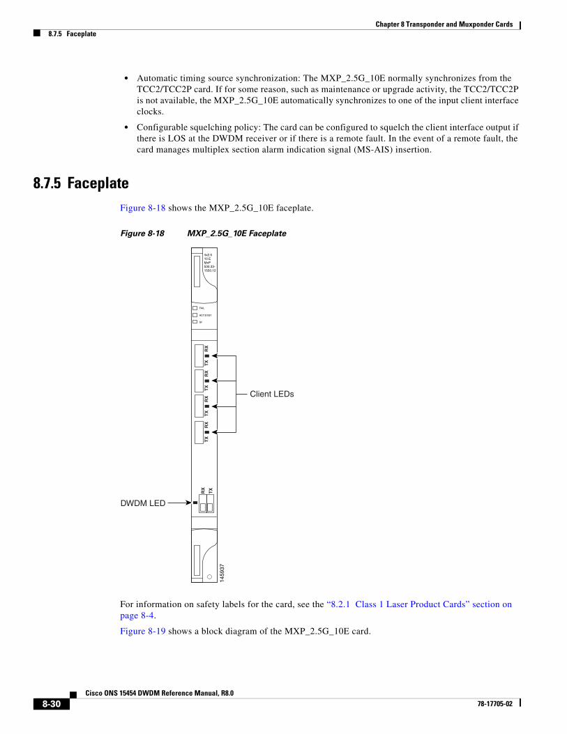
8.7.5 FaceplateFigure 8-18 shows the MXP_2.5G_10E faceplate.
Figure 8-18 MXP_2.5G_10E Faceplate
For information on safety labels for the card, see the “8.2.1 Class 1 Laser Product Cards” section on page 8-4.
Figure 8-19 shows a block diagram of the MXP_2.5G_10E card.
1459
37
FAIL
ACT/STBY
SF
4x2.510 EMxP530.33-1550.12
RX
TX
TX
RX
TX
RX
TX
RX
TX
RX
Client LEDs
DWDM LED
8-30Cisco ONS 15454 DWDM Reference Manual, R8.0
78-17705-02
Chapter 8 Transponder and Muxponder Cards8.7.6 Client Interfaces
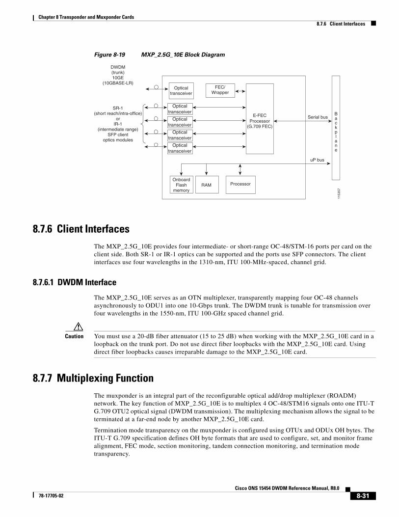
Figure 8-19 MXP_2.5G_10E Block Diagram
8.7.6 Client InterfacesThe MXP_2.5G_10E provides four intermediate- or short-range OC-48/STM-16 ports per card on the client side. Both SR-1 or IR-1 optics can be supported and the ports use SFP connectors. The client interfaces use four wavelengths in the 1310-nm, ITU 100-MHz-spaced, channel grid.
8.7.6.1 DWDM Interface
The MXP_2.5G_10E serves as an OTN multiplexer, transparently mapping four OC-48 channels asynchronously to ODU1 into one 10-Gbps trunk. The DWDM trunk is tunable for transmission over four wavelengths in the 1550-nm, ITU 100-GHz spaced channel grid.
Caution You must use a 20-dB fiber attenuator (15 to 25 dB) when working with the MXP_2.5G_10E card in a loopback on the trunk port. Do not use direct fiber loopbacks with the MXP_2.5G_10E card. Using direct fiber loopbacks causes irreparable damage to the MXP_2.5G_10E card.
8.7.7 Multiplexing FunctionThe muxponder is an integral part of the reconfigurable optical add/drop multiplexer (ROADM) network. The key function of MXP_2.5G_10E is to multiplex 4 OC-48/STM16 signals onto one ITU-T G.709 OTU2 optical signal (DWDM transmission). The multiplexing mechanism allows the signal to be terminated at a far-end node by another MXP_2.5G_10E card.
Termination mode transparency on the muxponder is configured using OTUx and ODUx OH bytes. The ITU-T G.709 specification defines OH byte formats that are used to configure, set, and monitor frame alignment, FEC mode, section monitoring, tandem connection monitoring, and termination mode transparency.
uP bus
Serial bus
ProcessorOnboard
Flashmemory
RAM
Opticaltransceiver
1153
57
FEC/Wrapper
Processor(G.709 FEC)
E-FEC
DWDM(trunk)10GE
(10GBASE-LR)
SR-1(short reach/intra-office)
orIR-1
(intermediate range)SFP client
optics modulesOptical
transceiver
Opticaltransceiver
Opticaltransceiver
Opticaltransceiver B
ackplane
8-31Cisco ONS 15454 DWDM Reference Manual, R8.0
78-17705-02
Chapter 8 Transponder and Muxponder Cards8.7.8 Timing Synchronization
The MXP_2.5G_10E card performs ODU to OTU multiplexing as defined in ITU-T G.709. The ODU is the framing structure and byte definition (ITU-T G.709 digital wrapper) used to define the data payload coming into one of the SONET/SDH client interfaces on MXP_2.5G_10E. The term ODU1 refers to an ODU that operates at 2.5-Gbps line rate. On the MXP_2.5G_10E, there are four client interfaces that can be defined using ODU1 framing structure and format by asserting a ITU-T G.709 digital wrapper.
The output of the muxponder is a single 10-Gbps DWDM trunk interface defined using OTU2. It is within the OTU2 framing structure that FEC or E-FEC information is appended to enable error checking and correction.
8.7.8 Timing SynchronizationThe MXP_2.5G_10E card is synchronized to the TCC2/TCC2P clock during normal conditions and transmits the ITU-T G.709 frame using this clock. No holdover function is implemented. If neither TCC2/TCC2P clock is available, the MXP_2.5G_10E switches automatically (hitless) to the first of the four valid client clocks with no time restriction as to how long it can run on this clock. The MXP_2.5G_10E continues to monitor the TCC2/TCC2P card. If a TCC2/TCC2P card is restored to working order, the MXP_2.5G_10E reverts to the normal working mode of running from the TCC2/TCC2P clock. If there is no valid TCC2/TCC2P clock and all of the client channels become invalid, the card waits (no valid frames processed) until one of the TCC2/TCC2P cards supplies a valid clock. In addition, the card is allowed to select the recovered clock from one active and valid client channel and supply that clock to the TCC2/TCC2P card.
8.7.9 Enhanced FEC (E-FEC) CapabilityThe MXP_2.5G_10E can configure the FEC in three modes: NO FEC, FEC, and E-FEC. The output bit rate is always 10.7092 Gbps as defined in ITU-T G.709, but the error coding performance can be provisioned as follows:
• NO FEC—No FEC
• FEC—Standard ITU-T G.975 Reed-Solomon algorithm
• E-FEC—Standard ITU-T G.975.1 I.7, two orthogonally concatenated BCH super FEC code. This FEC scheme contains three parameterizations of the same scheme of two orthogonally interleaved BCH. The constructed code is decoded iteratively to achieve the expected performance.
8.7.10 FEC and E-FEC ModesAs client side traffic passes through the MXP_2.5G_10E card, it can be digitally wrapped using FEC mode error correction or E-FEC mode error correction (or no error correction at all). The FEC mode setting provides a lower level of error detection and correction than the E-FEC mode setting of the card. As a result, using E-FEC mode allows higher sensitivity (lower OSNR) with a lower BER than FEC mode. E-FEC enables longer distance trunk-side transmission than with FEC.
The E-FEC feature is one of three basic modes of FEC operation. FEC can be turned off, FEC can be turned on, or E-FEC can be turned on to provide greater range and lower BER. The default mode is FEC on and E-FEC off. E-FEC is provisioned using CTC.
8-32Cisco ONS 15454 DWDM Reference Manual, R8.0
78-17705-02
Chapter 8 Transponder and Muxponder Cards8.7.11 SONET/SDH Overhead Byte Processing
8.7.11 SONET/SDH Overhead Byte ProcessingThe card passes the incoming SONET/SDH data stream and its overhead bytes for the client signal transparently. The card can be provisioned to terminate regenerator section overhead. This is used to eliminate forwarding of unneeded layer overhead. It can help reduce the number of alarms and help isolate faults in the network.
8.7.12 Client Interface MonitoringThe following parameters are monitored on the MXP_2.5G_10E card:
• Laser bias current is measured as a PM parameter
• LOS is detected and signaled
• Transmit (TX) and receive (RX) power are monitored
The following parameters are monitored in real time mode (one second):
• Optical power transmitted (client)
• Optical power received (client)
In case of loss of communication (LOC) at the DWDM receiver or far-end LOS, the client interface behavior is configurable. AIS can be invoked or the client signal can be squelched.
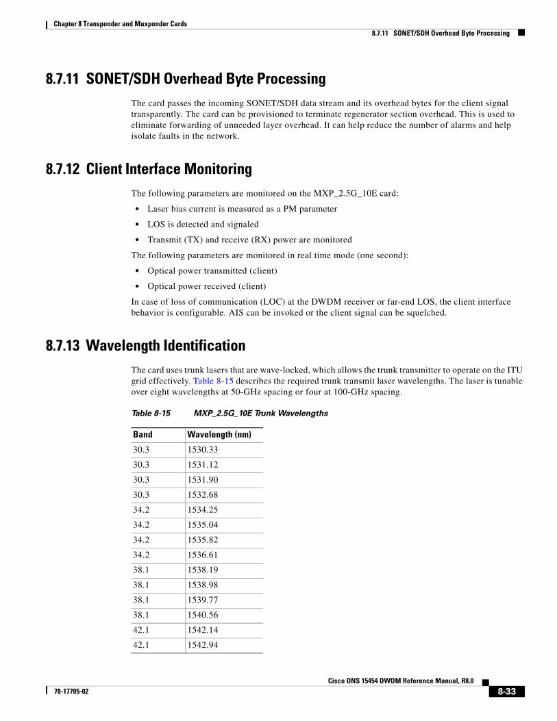
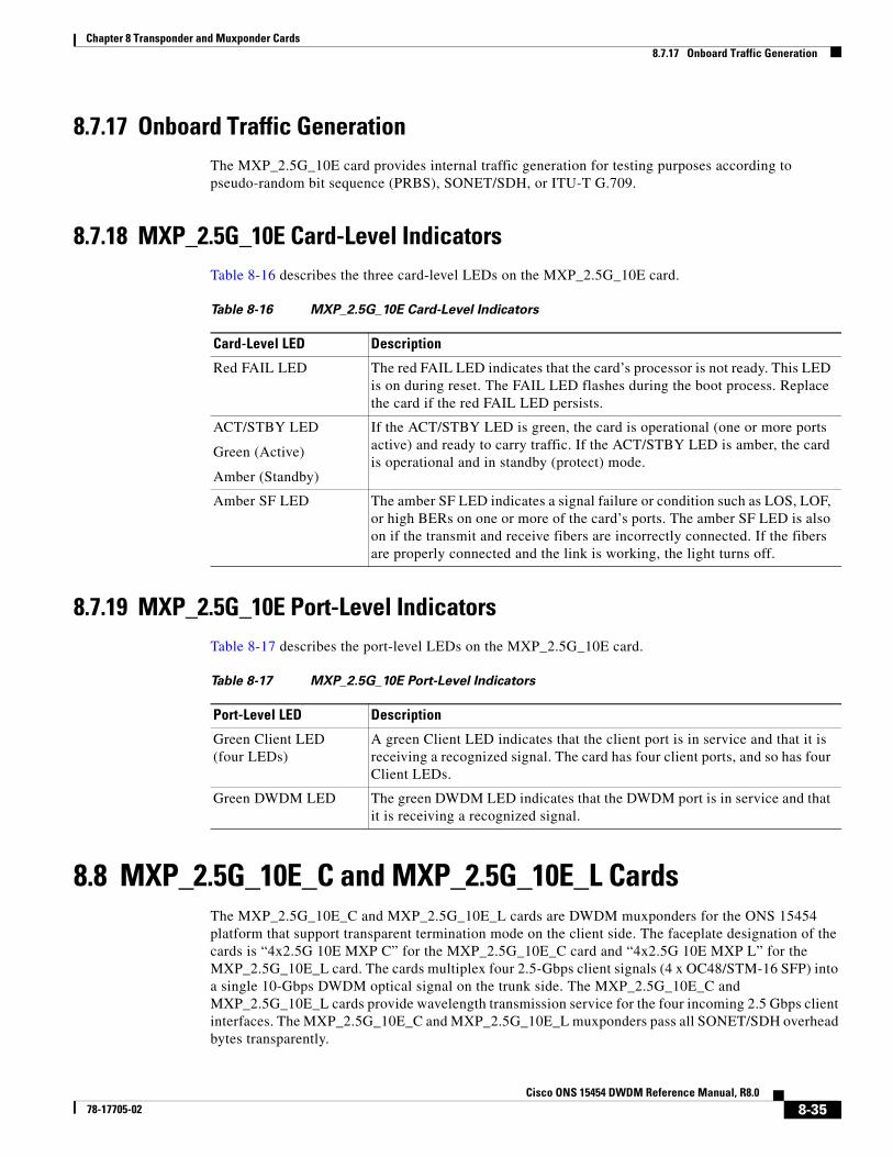
8.7.13 Wavelength IdentificationThe card uses trunk lasers that are wave-locked, which allows the trunk transmitter to operate on the ITU grid effectively. Table 8-15 describes the required trunk transmit laser wavelengths. The laser is tunable over eight wavelengths at 50-GHz spacing or four at 100-GHz spacing.
Table 8-15 MXP_2.5G_10E Trunk Wavelengths
Band Wavelength (nm)
30.3 1530.33
30.3 1531.12
30.3 1531.90
30.3 1532.68
34.2 1534.25
34.2 1535.04
34.2 1535.82
34.2 1536.61
38.1 1538.19
38.1 1538.98
38.1 1539.77
38.1 1540.56
42.1 1542.14
42.1 1542.94
8-33Cisco ONS 15454 DWDM Reference Manual, R8.0
78-17705-02
Chapter 8 Transponder and Muxponder Cards8.7.14 Automatic Laser Shutdown
8.7.14 Automatic Laser ShutdownThe ALS procedure is supported on both client and trunk interfaces. On the client interface, ALS is compliant with ITU-T G.664 (6/99). On the data application and trunk interface, the switch on and off pulse duration is greater than 60 seconds. The on and off pulse duration is user-configurable. For details regarding ALS provisioning for the MXP_2.5G_10E card, refer to the Cisco ONS 15454 DWDM Procedure Guide.
8.7.15 JitterFor SONET and SDH signals, the MXP_2.5G_10E card complies with Telcordia GR-253-CORE, ITU-T G.825, and ITU-T G.873 for jitter generation, jitter tolerance, and jitter transfer. See the “8.15 Jitter Considerations” section on page 8-76 for more information.
8.7.16 Lamp TestThe MXP_2.5G_10E card supports a lamp test function that is activated from the ONS 15454 front panel or through CTC to ensure that all LEDs are functional.
42.1 1543.73
42.1 1544.53
46.1 1546.12
46.1 1546.92
46.1 1547.72
46.1 1548.51
50.1 1550.12
50.1 1550.92
50.1 1551.72
50.1 1552.52
54.1 1554.13
54.1 1554.94
54.1 1555.75
54.1 1556.55
58.1 1558.17
58.1 1558.98
58.1 1559.79
58.1 1560.61
Table 8-15 MXP_2.5G_10E Trunk Wavelengths (continued)
Band Wavelength (nm)
8-34Cisco ONS 15454 DWDM Reference Manual, R8.0
78-17705-02
Chapter 8 Transponder and Muxponder Cards8.7.17 Onboard Traffic Generation
8.7.17 Onboard Traffic GenerationThe MXP_2.5G_10E card provides internal traffic generation for testing purposes according to pseudo-random bit sequence (PRBS), SONET/SDH, or ITU-T G.709.
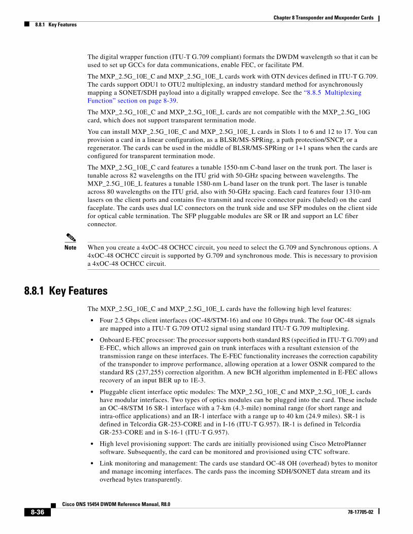
8.7.18 MXP_2.5G_10E Card-Level IndicatorsTable 8-16 describes the three card-level LEDs on the MXP_2.5G_10E card.
8.7.19 MXP_2.5G_10E Port-Level IndicatorsTable 8-17 describes the port-level LEDs on the MXP_2.5G_10E card.
8.8 MXP_2.5G_10E_C and MXP_2.5G_10E_L Cards The MXP_2.5G_10E_C and MXP_2.5G_10E_L cards are DWDM muxponders for the ONS 15454 platform that support transparent termination mode on the client side. The faceplate designation of the cards is “4x2.5G 10E MXP C” for the MXP_2.5G_10E_C card and “4x2.5G 10E MXP L” for the MXP_2.5G_10E_L card. The cards multiplex four 2.5-Gbps client signals (4 x OC48/STM-16 SFP) into a single 10-Gbps DWDM optical signal on the trunk side. The MXP_2.5G_10E_C and MXP_2.5G_10E_L cards provide wavelength transmission service for the four incoming 2.5 Gbps client interfaces. The MXP_2.5G_10E_C and MXP_2.5G_10E_L muxponders pass all SONET/SDH overhead bytes transparently.
Table 8-16 MXP_2.5G_10E Card-Level Indicators
Card-Level LED Description
Red FAIL LED The red FAIL LED indicates that the card’s processor is not ready. This LED is on during reset. The FAIL LED flashes during the boot process. Replace the card if the red FAIL LED persists.
ACT/STBY LED
Green (Active)
Amber (Standby)
If the ACT/STBY LED is green, the card is operational (one or more ports active) and ready to carry traffic. If the ACT/STBY LED is amber, the card is operational and in standby (protect) mode.
Amber SF LED The amber SF LED indicates a signal failure or condition such as LOS, LOF, or high BERs on one or more of the card’s ports. The amber SF LED is also on if the transmit and receive fibers are incorrectly connected. If the fibers are properly connected and the link is working, the light turns off.
Table 8-17 MXP_2.5G_10E Port-Level Indicators
Port-Level LED Description
Green Client LED(four LEDs)
A green Client LED indicates that the client port is in service and that it is receiving a recognized signal. The card has four client ports, and so has four Client LEDs.
Green DWDM LED The green DWDM LED indicates that the DWDM port is in service and that it is receiving a recognized signal.
8-35Cisco ONS 15454 DWDM Reference Manual, R8.0
78-17705-02
Chapter 8 Transponder and Muxponder Cards8.8.1 Key Features
The digital wrapper function (ITU-T G.709 compliant) formats the DWDM wavelength so that it can be used to set up GCCs for data communications, enable FEC, or facilitate PM.
The MXP_2.5G_10E_C and MXP_2.5G_10E_L cards work with OTN devices defined in ITU-T G.709. The cards support ODU1 to OTU2 multiplexing, an industry standard method for asynchronously mapping a SONET/SDH payload into a digitally wrapped envelope. See the “8.8.5 Multiplexing Function” section on page 8-39.
The MXP_2.5G_10E_C and MXP_2.5G_10E_L cards are not compatible with the MXP_2.5G_10G card, which does not support transparent termination mode.
You can install MXP_2.5G_10E_C and MXP_2.5G_10E_L cards in Slots 1 to 6 and 12 to 17. You can provision a card in a linear configuration, as a BLSR/MS-SPRing, a path protection/SNCP, or a regenerator. The cards can be used in the middle of BLSR/MS-SPRing or 1+1 spans when the cards are configured for transparent termination mode.
The MXP_2.5G_10E_C card features a tunable 1550-nm C-band laser on the trunk port. The laser is tunable across 82 wavelengths on the ITU grid with 50-GHz spacing between wavelengths. The MXP_2.5G_10E_L features a tunable 1580-nm L-band laser on the trunk port. The laser is tunable across 80 wavelengths on the ITU grid, also with 50-GHz spacing. Each card features four 1310-nm lasers on the client ports and contains five transmit and receive connector pairs (labeled) on the card faceplate. The cards uses dual LC connectors on the trunk side and use SFP modules on the client side for optical cable termination. The SFP pluggable modules are SR or IR and support an LC fiber connector.
Note When you create a 4xOC-48 OCHCC circuit, you need to select the G.709 and Synchronous options. A 4xOC-48 OCHCC circuit is supported by G.709 and synchronous mode. This is necessary to provision a 4xOC-48 OCHCC circuit.
8.8.1 Key FeaturesThe MXP_2.5G_10E_C and MXP_2.5G_10E_L cards have the following high level features:
• Four 2.5 Gbps client interfaces (OC-48/STM-16) and one 10 Gbps trunk. The four OC-48 signals are mapped into a ITU-T G.709 OTU2 signal using standard ITU-T G.709 multiplexing.
• Onboard E-FEC processor: The processor supports both standard RS (specified in ITU-T G.709) and E-FEC, which allows an improved gain on trunk interfaces with a resultant extension of the transmission range on these interfaces. The E-FEC functionality increases the correction capability of the transponder to improve performance, allowing operation at a lower OSNR compared to the standard RS (237,255) correction algorithm. A new BCH algorithm implemented in E-FEC allows recovery of an input BER up to 1E-3.
• Pluggable client interface optic modules: The MXP_2.5G_10E_C and MXP_2.5G_10E_L cards have modular interfaces. Two types of optics modules can be plugged into the card. These include an OC-48/STM 16 SR-1 interface with a 7-km (4.3-mile) nominal range (for short range and intra-office applications) and an IR-1 interface with a range up to 40 km (24.9 miles). SR-1 is defined in Telcordia GR-253-CORE and in I-16 (ITU-T G.957). IR-1 is defined in Telcordia GR-253-CORE and in S-16-1 (ITU-T G.957).
• High level provisioning support: The cards are initially provisioned using Cisco MetroPlanner software. Subsequently, the card can be monitored and provisioned using CTC software.
• Link monitoring and management: The cards use standard OC-48 OH (overhead) bytes to monitor and manage incoming interfaces. The cards pass the incoming SDH/SONET data stream and its overhead bytes transparently.
8-36Cisco ONS 15454 DWDM Reference Manual, R8.0
78-17705-02
Chapter 8 Transponder and Muxponder Cards8.8.2 Faceplate
• Control of layered SONET/SDH transport overhead: The cards are provisionable to terminate regenerator section overhead. This is used to eliminate forwarding of unneeded layer overhead. It can help reduce the number of alarms and help isolate faults in the network.
• Automatic timing source synchronization: The MXP_2.5G_10E_C and MXP_2.5G_10E_L cards normally synchronize from the TCC2/TCC2P card. If for some reason, such as maintenance or upgrade activity, the TCC2/TCC2P is not available, the cards automatically synchronize to one of the input client interface clocks.
• Configurable squelching policy: The cards can be configured to squelch the client interface output if there is LOS at the DWDM receiver or if there is a remote fault. In the event of a remote fault, the card manages MS-AIS insertion.
• The cards are tunable across the full C band (MXP_2.5G_10E_C) or full L band (MXP_2.5G_10E_L), thus eliminating the need to use different versions of each card to provide tunability across specific wavelengths in a band.
8.8.2 FaceplateFigure 8-20 shows the MXP_2.5G_10E_C and MXP_2.5G_10E_L faceplates and block diagram.
8-37Cisco ONS 15454 DWDM Reference Manual, R8.0
78-17705-02
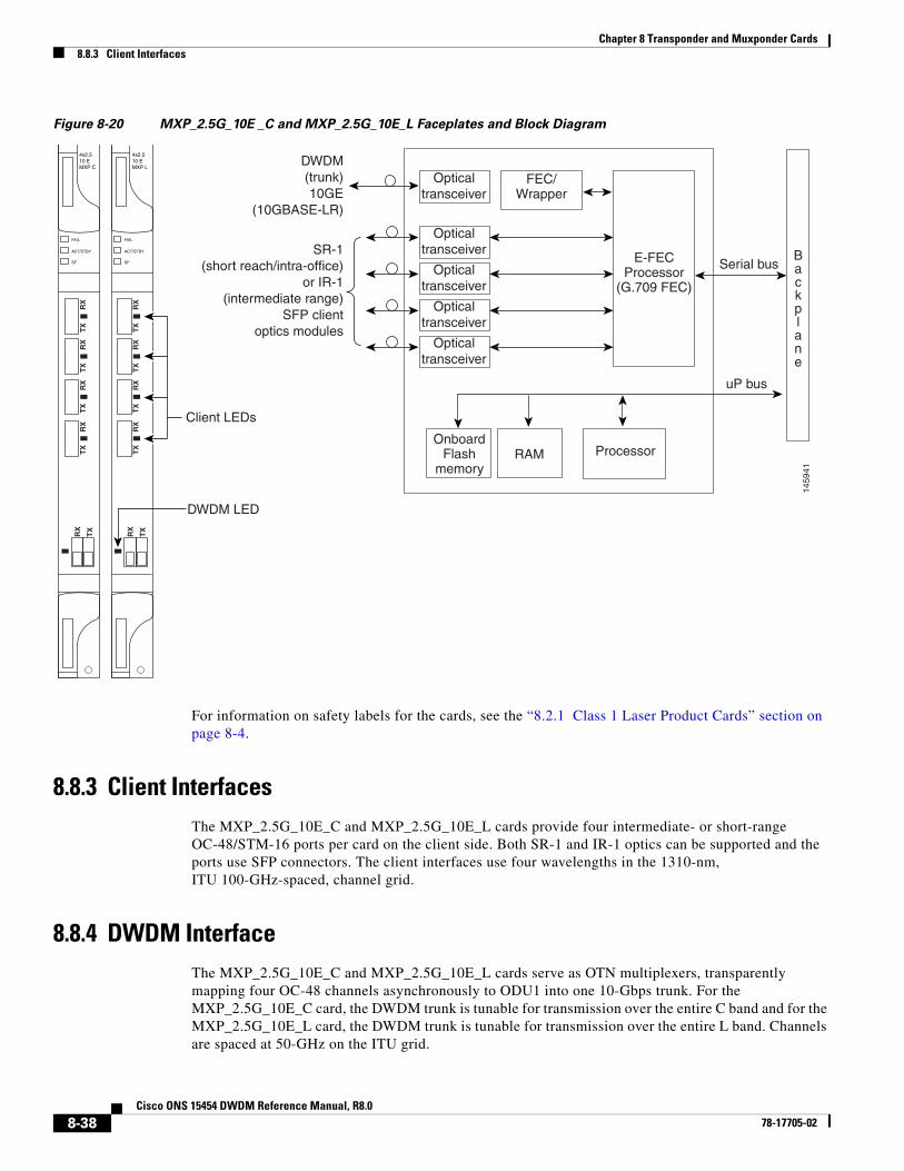
Chapter 8 Transponder and Muxponder Cards8.8.3 Client Interfaces
Figure 8-20 MXP_2.5G_10E _C and MXP_2.5G_10E_L Faceplates and Block Diagram
For information on safety labels for the cards, see the “8.2.1 Class 1 Laser Product Cards” section on page 8-4.
8.8.3 Client Interfaces The MXP_2.5G_10E_C and MXP_2.5G_10E_L cards provide four intermediate- or short-range OC-48/STM-16 ports per card on the client side. Both SR-1 and IR-1 optics can be supported and the ports use SFP connectors. The client interfaces use four wavelengths in the 1310-nm, ITU 100-GHz-spaced, channel grid.
8.8.4 DWDM InterfaceThe MXP_2.5G_10E_C and MXP_2.5G_10E_L cards serve as OTN multiplexers, transparently mapping four OC-48 channels asynchronously to ODU1 into one 10-Gbps trunk. For the MXP_2.5G_10E_C card, the DWDM trunk is tunable for transmission over the entire C band and for the MXP_2.5G_10E_L card, the DWDM trunk is tunable for transmission over the entire L band. Channels are spaced at 50-GHz on the ITU grid.
FAIL
ACT/STBY
SF
4x2.510 EMXP C
RX
TX
TX
RX
TX
RX
TX
RX
TX
RX
FAIL
ACT/STBY
SF
4x2.510 EMXP L
RX
TX
TX
RX
TX
RX
TX
RX
TX
RX
ProcessorRAM
1459
41
Opticaltransceiver
Opticaltransceiver
Opticaltransceiver
Opticaltransceiver
Opticaltransceiver
Backplane
FEC/Wrapper
E-FECProcessor
(G.709 FEC)
Serial bus
uP bus
OnboardFlash
memory
Client LEDs
DWDM LED
SR-1(short reach/intra-office)
or IR-1(intermediate range)
SFP clientoptics modules
DWDM(trunk)10GE
(10GBASE-LR)
8-38Cisco ONS 15454 DWDM Reference Manual, R8.0
78-17705-02
Chapter 8 Transponder and Muxponder Cards8.8.5 Multiplexing Function
Caution You must use a 20-dB fiber attenuator (15 to 25 dB) when working with the cards in a loopback on the trunk port. Do not use direct fiber loopbacks with the cards. Using direct fiber loopbacks causes irreparable damage to the MXP_2.5G_10E_C and MXP_2.5G_10E_L cards.
8.8.5 Multiplexing FunctionThe muxponder is an integral part of the ROADM network. The key function of the MXP_2.5G_10E_C and MXP_2.5G_10E_L cards is to multiplex four OC-48/STM16 signals onto one ITU-T G.709 OTU2 optical signal (DWDM transmission). The multiplexing mechanism allows the signal to be terminated at a far-end node by another similar card.
Transparent termination on the muxponder is configured using OTUx and ODUx OH bytes. The ITU-T G.709 specification defines OH byte formats that are used to configure, set, and monitor frame alignment, FEC mode, section monitoring, tandem connection monitoring, and transparent termination mode.
The MXP_2.5G_10E and MXP_2.5G_10E_L cards perform ODU to OTU multiplexing as defined in ITU-T G.709. The ODU is the framing structure and byte definition (ITU-T G.709 digital wrapper) used to define the data payload coming into one of the SONET/SDH client interfaces on the cards. The term ODU1 refers to an ODU that operates at 2.5-Gbps line rate. On the cards, there are four client interfaces that can be defined using ODU1 framing structure and format by asserting a ITU-T G.709 digital wrapper.
The output of the muxponder is a single 10-Gbps DWDM trunk interface defined using OTU2. It is within the OTU2 framing structure that FEC or E-FEC information is appended to enable error checking and correction.
8.8.6 Timing SynchronizationThe MXP_2.5G_10E_C and MXP_2.5G_10E_L cards are synchronized to the TCC2/TCC2P clock during normal conditions and transmit the ITU-T G.709 frame using this clock. No holdover function is implemented. If neither TCC2/TCC2P clock is available, the card switches automatically (hitless) to the first of the four valid client clocks with no time restriction as to how long it can run on this clock. The card continues to monitor the TCC2/TCC2P card. If a TCC2/TCC2P card is restored to working order, the card reverts to the normal working mode of running from the TCC2/TCC2P clock. If there is no valid TCC2/TCC2P clock and all of the client channels become invalid, the card waits (no valid frames processed) until one of the TCC2/TCC2P cards supplies a valid clock. In addition, the card is allowed to select the recovered clock from one active and valid client channel and supply that clock to the TCC2/TCC2P card.
8.8.7 Enhanced FEC (E-FEC) CapabilityThe MXP_2.5G_10E_C and MXP_2.5G_10E_L cards can configure the FEC in three modes: NO FEC, FEC, and E-FEC. The output bit rate is always 10.7092 Gbps as defined in ITU-T G.709, but the error coding performance can be provisioned as follows:
• NO FEC—No FEC
• FEC—Standard ITU-T G.975 Reed-Solomon algorithm
8-39Cisco ONS 15454 DWDM Reference Manual, R8.0
78-17705-02
Chapter 8 Transponder and Muxponder Cards8.8.8 FEC and E-FEC Modes
• E-FEC—Standard ITU-T G.975.1 I.7, two orthogonally concatenated BCH super FEC code. This FEC scheme contains three parameterizations of the same scheme of two orthogonally interleaved block codes (BCH). The constructed code is decoded iteratively to achieve the expected performance.
8.8.8 FEC and E-FEC ModesAs client side traffic passes through the card, it can be digitally wrapped using FEC mode error correction or E-FEC mode error correction (or no error correction at all). The FEC mode setting provides a lower level of error detection and correction than the E-FEC mode setting of the card. As a result, using E-FEC mode allows higher sensitivity (lower OSNR) with a lower BER than FEC mode. E-FEC enables longer distance trunk-side transmission than with FEC.
The E-FEC feature is one of three basic modes of FEC operation. FEC can be turned off, FEC can be turned on, or E-FEC can be turned on to provide greater range and lower BER. The default mode is FEC on and E-FEC off. E-FEC is provisioned using CTC.
8.8.9 SONET/SDH Overhead Byte ProcessingThe card passes the incoming SONET/SDH data stream and its overhead bytes for the client signal transparently. The card can be provisioned to terminate regenerator section overhead. This is used to eliminate forwarding of unneeded layer overhead. It can help reduce the number of alarms and help isolate faults in the network.
8.8.10 Client Interface MonitoringThe following parameters are monitored on the MXP_2.5G_10E_C and MXP_2.5G_10E_L cards:
• Laser bias current is measured as a PM parameter.
• LOS is detected and signaled.
• Rx and Tx power are monitored.
The following parameters are monitored in real time mode (one second):
• Optical power transmitted (client)
• Optical power received (client)
In case of LOC at the DWDM receiver or far-end LOS, the client interface behavior is configurable. AIS can be invoked or the client signal can be squelched.
8.8.11 Wavelength IdentificationThe card uses trunk lasers that are wavelocked, which allows the trunk transmitter to operate on the ITU grid effectively. Both the MXP_2.5G_10E_C and MXP_2.5G_10E_L cards implement the UT2 module. The MXP_2.5G_10E_C card uses a C-band version of the UT2 and the MXP_2.5G_10E_L card uses an L-band version.
Table 8-18 describes the required trunk transmit laser wavelengths for the MXP_2.5G_10E_C card. The laser is tunable over 82 wavelengths in the C band at 50-GHz spacing on the ITU grid.
8-40Cisco ONS 15454 DWDM Reference Manual, R8.0
78-17705-02

Chapter 8 Transponder and Muxponder Cards8.8.11 Wavelength Identification
Table 8-18 MXP_2.5G_10E_C Trunk Wavelengths
Channel Number
Frequency (THz)
Wavelength (nm)
Channel Number
Frequency (THz)
Wavelength (nm)
1 196.00 1529.55 42 193.95 1545.72
2 195.95 1529.94 43 193.90 1546.119
3 195.90 1530.334 44 193.85 1546.518
4 195.85 1530.725 45 193.80 1546.917
5 195.80 1531.116 46 193.75 1547.316
6 195.75 1531.507 47 193.70 1547.715
7 195.70 1531.898 48 193.65 1548.115
8 195.65 1532.290 49 193.60 1548.515
9 195.60 1532.681 50 193.55 1548.915
10 195.55 1533.073 51 193.50 1549.32
11 195.50 1533.47 52 193.45 1549.71
12 195.45 1533.86 53 193.40 1550.116
13 195.40 1534.250 54 193.35 1550.517
14 195.35 1534.643 55 193.30 1550.918
15 195.30 1535.036 56 193.25 1551.319
16 195.25 1535.429 57 193.20 1551.721
17 195.20 1535.822 58 193.15 1552.122
18 195.15 1536.216 59 193.10 1552.524
19 195.10 1536.609 60 193.05 1552.926
20 195.05 1537.003 61 193.00 1553.33
21 195.00 1537.40 62 192.95 1553.73
22 194.95 1537.79 63 192.90 1554.134
23 194.90 1538.186 64 192.85 1554.537
24 194.85 1538.581 65 192.80 1554.940
25 194.80 1538.976 66 192.75 1555.343
26 194.75 1539.371 67 192.70 1555.747
27 194.70 1539.766 68 192.65 1556.151
28 194.65 1540.162 69 192.60 1556.555
29 194.60 1540.557 70 192.55 1556.959
30 194.55 1540.953 71 192.50 1557.36
31 194.50 1541.35 72 192.45 1557.77
32 194.45 1541.75 73 192.40 1558.173
33 194.40 1542.142 74 192.35 1558.578
34 194.35 1542.539 75 192.30 1558.983
35 194.30 1542.936 76 192.25 1559.389
8-41Cisco ONS 15454 DWDM Reference Manual, R8.0
78-17705-02

Chapter 8 Transponder and Muxponder Cards8.8.11 Wavelength Identification
Table 8-19 describes the required trunk transmit laser wavelengths for the MXP_2.5G_10E_L card. The laser is fully tunable over 80 wavelengths in the L band at 50-GHz spacing on the ITU grid.
36 194.25 1543.333 77 192.20 1559.794
37 194.20 1543.730 78 192.15 1560.200
38 194.15 1544.128 79 192.10 1560.606
39 194.10 1544.526 80 192.05 1561.013
40 194.05 1544.924 81 192.00 1561.42
41 194.00 1545.32 82 191.95 1561.83
Table 8-18 MXP_2.5G_10E_C Trunk Wavelengths (continued)
Channel Number
Frequency (THz)
Wavelength (nm)
Channel Number
Frequency (THz)
Wavelength (nm)
Table 8-19 MXP_2.5G_10E_L Trunk Wavelengths
Channel Number
Frequency (THz)
Wavelength (nm)
Channel Number
Frequency (THz)
Wavelength (nm)
1 190.85 1570.83 41 188.85 1587.46
2 190.8 1571.24 42 188.8 1587.88
3 190.75 1571.65 43 188.75 1588.30
4 190.7 1572.06 44 188.7 1588.73
5 190.65 1572.48 45 188.65 1589.15
6 190.6 1572.89 46 188.6 1589.57
7 190.55 1573.30 47 188.55 1589.99
8 190.5 1573.71 48 188.5 1590.41
9 190.45 1574.13 49 188.45 1590.83
10 190.4 1574.54 50 188.4 1591.26
11 190.35 1574.95 51 188.35 1591.68
12 190.3 1575.37 52 188.3 1592.10
13 190.25 1575.78 53 188.25 1592.52
14 190.2 1576.20 54 188.2 1592.95
15 190.15 1576.61 55 188.15 1593.37
16 190.1 1577.03 56 188.1 1593.79
17 190.05 1577.44 57 188.05 1594.22
18 190 1577.86 58 188 1594.64
19 189.95 1578.27 59 187.95 1595.06
20 189.9 1578.69 60 187.9 1595.49
21 189.85 1579.10 61 187.85 1595.91
22 189.8 1579.52 62 187.8 1596.34
23 189.75 1579.93 63 187.75 1596.76
8-42Cisco ONS 15454 DWDM Reference Manual, R8.0
78-17705-02
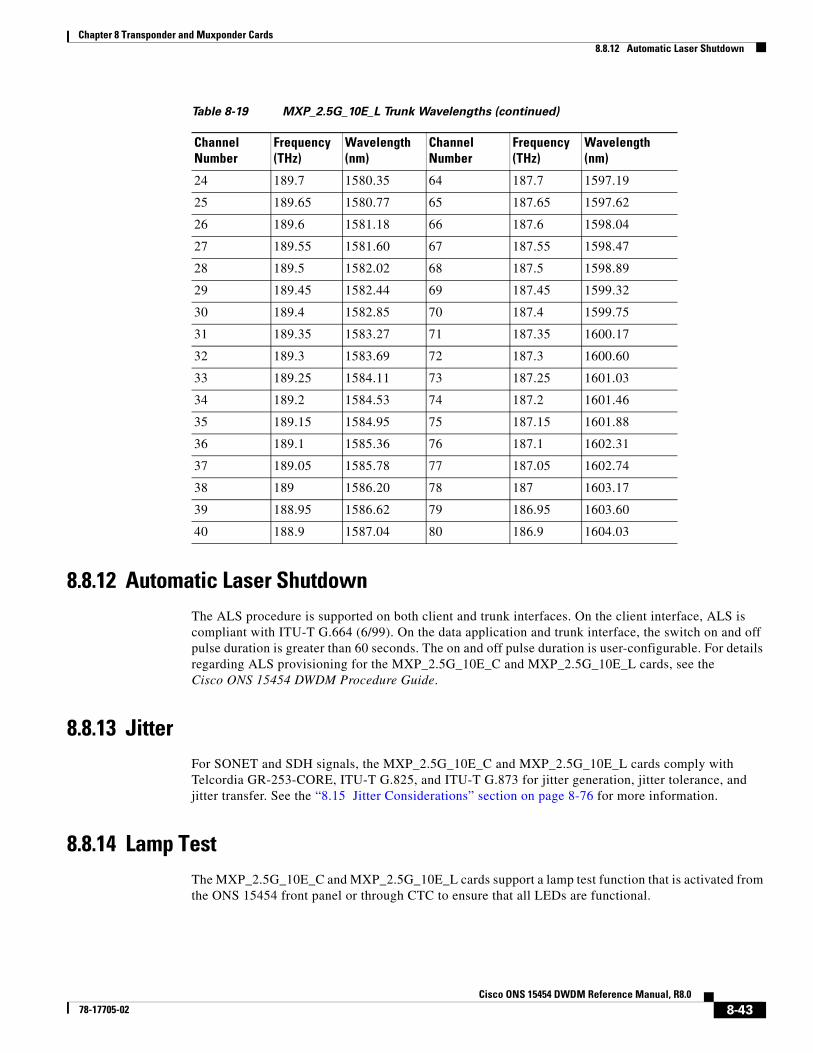
Chapter 8 Transponder and Muxponder Cards8.8.12 Automatic Laser Shutdown
8.8.12 Automatic Laser ShutdownThe ALS procedure is supported on both client and trunk interfaces. On the client interface, ALS is compliant with ITU-T G.664 (6/99). On the data application and trunk interface, the switch on and off pulse duration is greater than 60 seconds. The on and off pulse duration is user-configurable. For details regarding ALS provisioning for the MXP_2.5G_10E_C and MXP_2.5G_10E_L cards, see the Cisco ONS 15454 DWDM Procedure Guide.
8.8.13 JitterFor SONET and SDH signals, the MXP_2.5G_10E_C and MXP_2.5G_10E_L cards comply with Telcordia GR-253-CORE, ITU-T G.825, and ITU-T G.873 for jitter generation, jitter tolerance, and jitter transfer. See the “8.15 Jitter Considerations” section on page 8-76 for more information.
8.8.14 Lamp TestThe MXP_2.5G_10E_C and MXP_2.5G_10E_L cards support a lamp test function that is activated from the ONS 15454 front panel or through CTC to ensure that all LEDs are functional.
24 189.7 1580.35 64 187.7 1597.19
25 189.65 1580.77 65 187.65 1597.62
26 189.6 1581.18 66 187.6 1598.04
27 189.55 1581.60 67 187.55 1598.47
28 189.5 1582.02 68 187.5 1598.89
29 189.45 1582.44 69 187.45 1599.32
30 189.4 1582.85 70 187.4 1599.75
31 189.35 1583.27 71 187.35 1600.17
32 189.3 1583.69 72 187.3 1600.60
33 189.25 1584.11 73 187.25 1601.03
34 189.2 1584.53 74 187.2 1601.46
35 189.15 1584.95 75 187.15 1601.88
36 189.1 1585.36 76 187.1 1602.31
37 189.05 1585.78 77 187.05 1602.74
38 189 1586.20 78 187 1603.17
39 188.95 1586.62 79 186.95 1603.60
40 188.9 1587.04 80 186.9 1604.03
Table 8-19 MXP_2.5G_10E_L Trunk Wavelengths (continued)
Channel Number
Frequency (THz)
Wavelength (nm)
Channel Number
Frequency (THz)
Wavelength (nm)
8-43Cisco ONS 15454 DWDM Reference Manual, R8.0
78-17705-02
Chapter 8 Transponder and Muxponder Cards8.8.15 Onboard Traffic Generation
8.8.15 Onboard Traffic GenerationThe MXP_2.5G_10E_C and MXP_2.5G_10E_L cards provide internal traffic generation for testing purposes according to PRBS, SONET/SDH, or ITU-T G.709.
8.8.16 MXP_2.5G_10E_C and MXP_2.5G_10E_L Card-Level IndicatorsTable 8-20 describes the three card-level LEDs on the MXP_2.5G_10E_C and MXP_2.5G_10E_L cards.
8.8.17 MXP_2.5G_10E and MXP_2.5G_10E_L Port-Level IndicatorsTable 8-21 describes the port-level LEDs on the MXP_2.5G_10E_C and MXP_2.5G_10E_L cards.
8.9 MXP_MR_2.5G and MXPP_MR_2.5G CardsThe MXP_MR_2.5G card aggregates a mix and match of client Storage Area Network (SAN) service client inputs (GE, FICON, Fibre Channel, and ESCON) into one 2.5 Gbps STM-16/OC-48 DWDM signal on the trunk side. It provides one long-reach STM-16/OC-48 port per card and is compliant with Telcordia GR-253-CORE.
Table 8-20 MXP_2.5G_10E_C and MXP_2.5G_10E_L Card-Level Indicators
Card-Level LED Description
Red FAIL LED The red FAIL LED indicates that the card’s processor is not ready. This LED is on during reset. The FAIL LED flashes during the boot process. Replace the card if the red FAIL LED persists.
ACT/STBY LED
Green (Active)
Amber (Standby)
If the ACT/STBY LED is green, the card is operational (one or more ports active) and ready to carry traffic. If the ACT/STBY LED is amber, the card is operational and in standby (protect) mode.
Amber SF LED The amber SF LED indicates a signal failure or condition such as LOS, LOF, or high BERs on one or more of the card’s ports. The amber SF LED is also on if the transmit and receive fibers are incorrectly connected. If the fibers are properly connected and the link is working, the light turns off.
Table 8-21 MXP_2.5G_10E_C and MXP_2.5G_10E_L Port-Level Indicators
Port-Level LED Description
Green Client LED(four LEDs)
A green Client LED indicates that the client port is in service and that it is receiving a recognized signal. The card has four client ports, and so has four Client LEDs.
Green DWDM LED The green DWDM LED indicates that the DWDM port is in service and that it is receiving a recognized signal.
8-44Cisco ONS 15454 DWDM Reference Manual, R8.0
78-17705-02
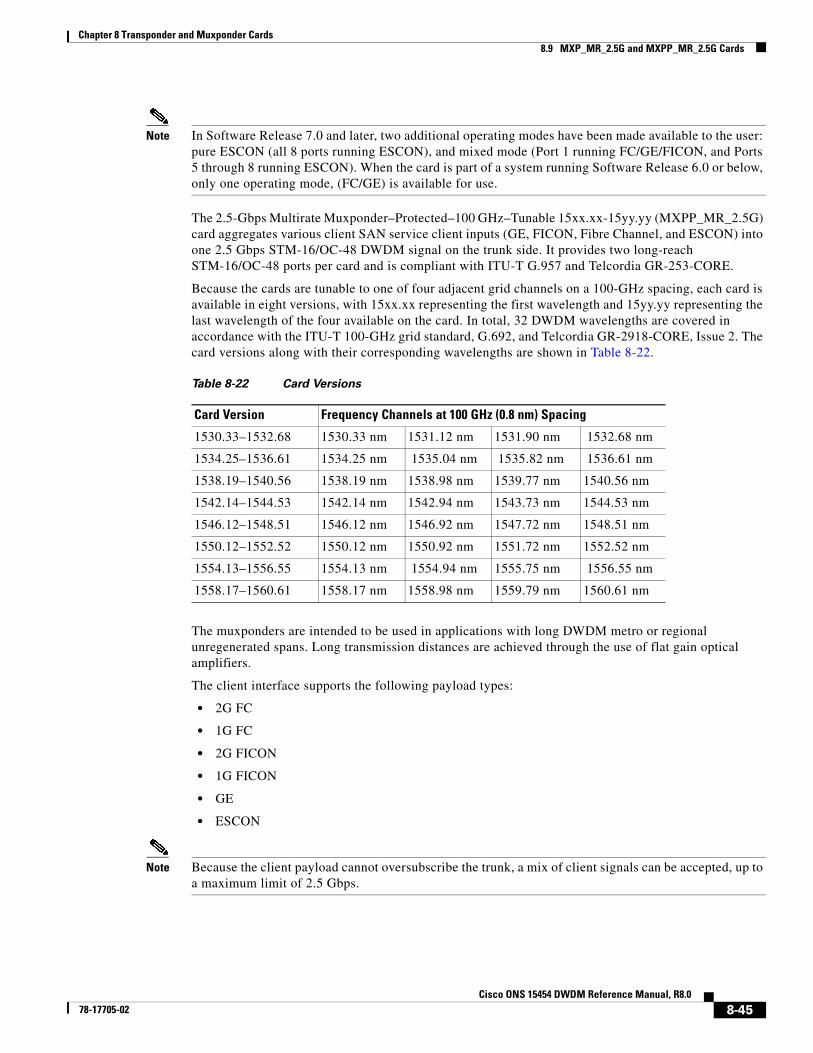
Chapter 8 Transponder and Muxponder Cards8.9 MXP_MR_2.5G and MXPP_MR_2.5G Cards
Note In Software Release 7.0 and later, two additional operating modes have been made available to the user: pure ESCON (all 8 ports running ESCON), and mixed mode (Port 1 running FC/GE/FICON, and Ports 5 through 8 running ESCON). When the card is part of a system running Software Release 6.0 or below, only one operating mode, (FC/GE) is available for use.
The 2.5-Gbps Multirate Muxponder–Protected–100 GHz–Tunable 15xx.xx-15yy.yy (MXPP_MR_2.5G) card aggregates various client SAN service client inputs (GE, FICON, Fibre Channel, and ESCON) into one 2.5 Gbps STM-16/OC-48 DWDM signal on the trunk side. It provides two long-reach STM-16/OC-48 ports per card and is compliant with ITU-T G.957 and Telcordia GR-253-CORE.
Because the cards are tunable to one of four adjacent grid channels on a 100-GHz spacing, each card is available in eight versions, with 15xx.xx representing the first wavelength and 15yy.yy representing the last wavelength of the four available on the card. In total, 32 DWDM wavelengths are covered in accordance with the ITU-T 100-GHz grid standard, G.692, and Telcordia GR-2918-CORE, Issue 2. The card versions along with their corresponding wavelengths are shown in Table 8-22.
The muxponders are intended to be used in applications with long DWDM metro or regional unregenerated spans. Long transmission distances are achieved through the use of flat gain optical amplifiers.
The client interface supports the following payload types:
• 2G FC
• 1G FC
• 2G FICON
• 1G FICON
• GE
• ESCON
Note Because the client payload cannot oversubscribe the trunk, a mix of client signals can be accepted, up to a maximum limit of 2.5 Gbps.
Table 8-22 Card Versions
Card Version Frequency Channels at 100 GHz (0.8 nm) Spacing
1530.33–1532.68 1530.33 nm 1531.12 nm 1531.90 nm 1532.68 nm
1534.25–1536.61 1534.25 nm 1535.04 nm 1535.82 nm 1536.61 nm
1538.19–1540.56 1538.19 nm 1538.98 nm 1539.77 nm 1540.56 nm
1542.14–1544.53 1542.14 nm 1542.94 nm 1543.73 nm 1544.53 nm
1546.12–1548.51 1546.12 nm 1546.92 nm 1547.72 nm 1548.51 nm
1550.12–1552.52 1550.12 nm 1550.92 nm 1551.72 nm 1552.52 nm
1554.13–1556.55 1554.13 nm 1554.94 nm 1555.75 nm 1556.55 nm
1558.17–1560.61 1558.17 nm 1558.98 nm 1559.79 nm 1560.61 nm
8-45Cisco ONS 15454 DWDM Reference Manual, R8.0
78-17705-02

Chapter 8 Transponder and Muxponder Cards8.9 MXP_MR_2.5G and MXPP_MR_2.5G Cards
Table 8-23 shows the input data rate for each client interface, and the encapsulation method. The current version of the ITU-T Transparent Generic Framing Procedure (GFP-T) G.7041 supports transparent mapping of 8B/10B block-coded protocols, including Gigabit Ethernet, Fibre Channel, and FICON.
In addition to the GFP mapping, 1-Gbps traffic on Port 1 or 2 of the high-speed serializer/deserializer (SERDES) is mapped to an STS-24c channel. If two 1-Gbps client signals are present at Port 1 and Port 2 of the SERDES, the Port 1 signal is mapped into the first STS-24c channel and the Port 2 signal into the second STS-24c channel. The two channels are then mapped into an OC-48 trunk channel.
Table 8-24 shows some of the mix and match possibilities on the various client ports. The table is intended to show the full client payload configurations for the card.
Table 8-23 MXP_MR_2.5G and MXPP_MR_2.5G Client Interface Data Rates and Encapsulation
Client Interface Input Data Rate ITU-T GFP-T G.7041 Encapsulation
2G FC 2.125 Gbps Yes
1G FC 1.06 Gbps Yes
2G FICON 2.125 Gbps Yes
1G FICON 1.06 Gbps Yes
GE 1.25 Gbps Yes
ESCON 0.2 Gbps Yes
Table 8-24 Client Data Rates and Ports
Mode Port(s) Aggregate Data Rate
2G FC 1 2.125 Gbps
1G FC 1, 2 2.125 Gbps
2G FICON 1 2.125 Gbps
1G FICON 1, 2 2.125 Gbps
GE 1, 2 2.5 Gbps
1G FCESCON(mixed mode)
15, 6, 7, 8
1.06 Gbps0.8 Gbps
1.86 Gbps total
1G FICONESCON(mixed mode)
15, 6, 7, 8
1.06 Gbps0.8 Gbps
1.86 Gbps total
GEESCON(mixed mode)
15, 6, 7, 8
1.25 Gbps0.8 Gbps
Total 2.05 Gbps
ESCON 1, 2, 3, 4, 5, 6, 7, 8 1.6 Gbps
8-46Cisco ONS 15454 DWDM Reference Manual, R8.0
78-17705-02
Chapter 8 Transponder and Muxponder Cards8.9.1 Performance Monitoring
8.9.1 Performance MonitoringGFP-T performance monitoring (GFP-T PM) is available via remote monitoring (RMON), and trunk PM is managed according to Telcordia GR-253-CORE and ITU G.783/826. Client PM is achieved through RMON for FC and GE.
8.9.2 Distance ExtensionA buffer-to-buffer credit management scheme provides FC flow control. With this feature enabled, a port indicates the number of frames that can be sent to it (its buffer credit), before the sender is required to stop transmitting and wait for the receipt of a “ready” indication The MXP_MR_2.5G and MXPP_MR_2.5 cards support FC credit-based flow control with a buffer-to-buffer credit extension of up to 1600 km (994.2 miles) for 1G FC and up to 800 km (497.1 miles) for 2G FC. The feature can be enabled or disabled.
8.9.3 Slot CompatibilityYou can install MXP_MR_2.5G and MXPP_MR_2.5G cards in Slots 1 to 6 and 12 to 17. The TCC2/TCC2P card is the only other card required to be used with these muxponder cards. Cross-connect cards do not affect the operation of the muxponder cards.
8.9.4 Interoperability with Cisco MDS SwitchesYou can provision a string (port name) for each fiber channel/FICON interface on the MXP_MR_2.5G and MXPP_MR_2.5G cards, which allows the MDS Fabric Manager to create a link association between that SAN port and a SAN port on a Cisco MDS 9000 switch.
8.9.5 Client and Trunk PortsThe MXP_MR_2.5G card features a 1550-nm laser for the trunk/line port and a 1310-nm or 850-nm laser (depending on the SFP) for the client ports. The card contains eight 12.5 degree downward tilt SFP modules for the client interfaces. For optical termination, each SFP uses two LC connectors, which are labeled TX and RX on the faceplate. The trunk port is a dual-LC connector with a 45 degree downward angle.
The MXPP_MR_2.5G card features a 1550-nm laser for the trunk/line port and a 1310-nm or 850-nm laser (depending on the SFP) for the client port. The card contains eight 12.5 degree downward tilt SFP modules for the client interfaces. For optical termination, each SFP uses two LC connectors, which are labeled TX and RX on the faceplate. There are two trunk port connectors (one for working and one for protect). Each is a dual-LC connector with a 45-degree downward angle.
8.9.6 FaceplatesFigure 8-21 shows the MXP_MR_2.5G and MXPP_MR_2.5G faceplates.
8-47Cisco ONS 15454 DWDM Reference Manual, R8.0
78-17705-02
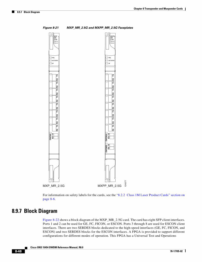
Chapter 8 Transponder and Muxponder Cards8.9.7 Block Diagram
Figure 8-21 MXP_MR_2.5G and MXPP_MR_2.5G Faceplates
For information on safety labels for the cards, see the “8.2.2 Class 1M Laser Product Cards” section on page 8-6.
8.9.7 Block DiagramFigure 8-22 shows a block diagram of the MXP_MR_2.5G card. The card has eight SFP client interfaces. Ports 1 and 2 can be used for GE, FC, FICON, or ESCON. Ports 3 through 8 are used for ESCON client interfaces. There are two SERDES blocks dedicated to the high-speed interfaces (GE, FC, FICON, and ESCON) and two SERDES blocks for the ESCON interfaces. A FPGA is provided to support different configurations for different modes of operation. This FPGA has a Universal Test and Operations
MXP_MR_2.5G MXPP_MR_2.5G 1240
77
MXPMR2.5G15xx.xx
15xx.xx
FAIL
ACT/STBY
SF
MXPPMR2.5G15xx.xx
15xx.xx
RX
TX
RX
TX
RX
TX
RX
TX
RX
TX
RX
TX
RX
TX
RX
TX
DW
DM
AD
WD
MB
FAIL
ACT/STBY
SF
RX
TX
RX
TX
RX
TX
RX
TX
RX
TX
RX
TX
RX
TX
RX
TX
RX
TX
RX
TX
DW
DM
RX
TX
8-48Cisco ONS 15454 DWDM Reference Manual, R8.0
78-17705-02
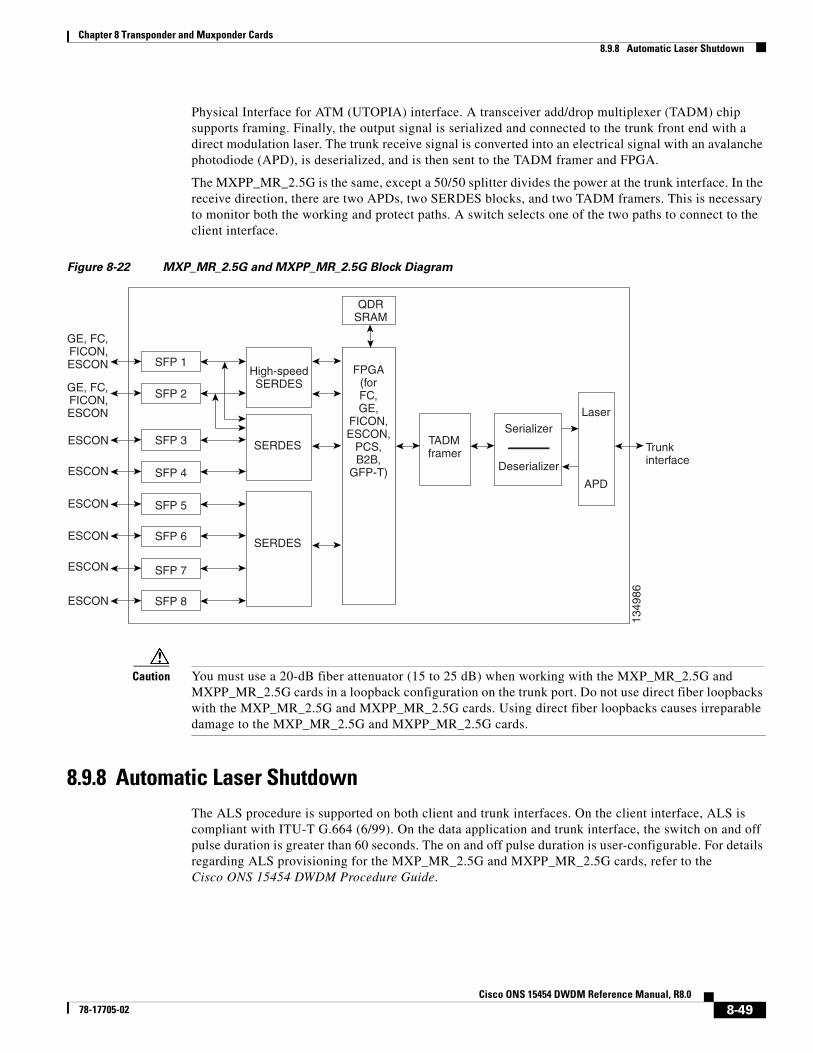
Chapter 8 Transponder and Muxponder Cards8.9.8 Automatic Laser Shutdown
Physical Interface for ATM (UTOPIA) interface. A transceiver add/drop multiplexer (TADM) chip supports framing. Finally, the output signal is serialized and connected to the trunk front end with a direct modulation laser. The trunk receive signal is converted into an electrical signal with an avalanche photodiode (APD), is deserialized, and is then sent to the TADM framer and FPGA.
The MXPP_MR_2.5G is the same, except a 50/50 splitter divides the power at the trunk interface. In the receive direction, there are two APDs, two SERDES blocks, and two TADM framers. This is necessary to monitor both the working and protect paths. A switch selects one of the two paths to connect to the client interface.
Figure 8-22 MXP_MR_2.5G and MXPP_MR_2.5G Block Diagram
Caution You must use a 20-dB fiber attenuator (15 to 25 dB) when working with the MXP_MR_2.5G and MXPP_MR_2.5G cards in a loopback configuration on the trunk port. Do not use direct fiber loopbacks with the MXP_MR_2.5G and MXPP_MR_2.5G cards. Using direct fiber loopbacks causes irreparable damage to the MXP_MR_2.5G and MXPP_MR_2.5G cards.
8.9.8 Automatic Laser ShutdownThe ALS procedure is supported on both client and trunk interfaces. On the client interface, ALS is compliant with ITU-T G.664 (6/99). On the data application and trunk interface, the switch on and off pulse duration is greater than 60 seconds. The on and off pulse duration is user-configurable. For details regarding ALS provisioning for the MXP_MR_2.5G and MXPP_MR_2.5G cards, refer to the Cisco ONS 15454 DWDM Procedure Guide.
SFP 1
SFP 6
SFP 5
SFP 4
SFP 3
SFP 2
SFP 8
SERDES
FPGA(forFC,GE,
FICON,ESCON,
PCS,B2B,
GFP-T)
SERDES
SFP 7
High-speedSERDES
QDRSRAM
TADMframer
Laser
APD
Serializer
Deserializer
ESCON
ESCON
ESCON
ESCON
ESCON
ESCON
Trunkinterface
1349
86
GE, FC,FICON,ESCON
GE, FC,FICON,ESCON
8-49Cisco ONS 15454 DWDM Reference Manual, R8.0
78-17705-02
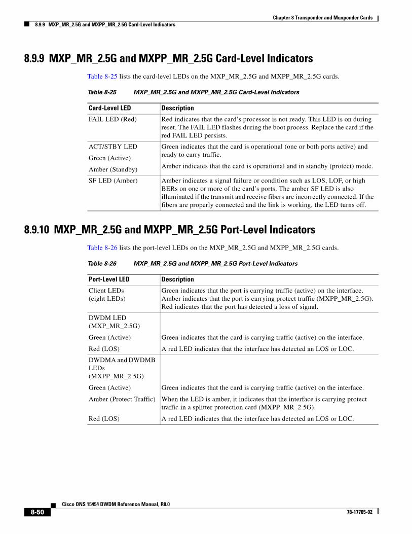
Chapter 8 Transponder and Muxponder Cards8.9.9 MXP_MR_2.5G and MXPP_MR_2.5G Card-Level Indicators
8.9.9 MXP_MR_2.5G and MXPP_MR_2.5G Card-Level IndicatorsTable 8-25 lists the card-level LEDs on the MXP_MR_2.5G and MXPP_MR_2.5G cards.
8.9.10 MXP_MR_2.5G and MXPP_MR_2.5G Port-Level IndicatorsTable 8-26 lists the port-level LEDs on the MXP_MR_2.5G and MXPP_MR_2.5G cards.
Table 8-25 MXP_MR_2.5G and MXPP_MR_2.5G Card-Level Indicators
Card-Level LED Description
FAIL LED (Red) Red indicates that the card’s processor is not ready. This LED is on during reset. The FAIL LED flashes during the boot process. Replace the card if the red FAIL LED persists.
ACT/STBY LED
Green (Active)
Amber (Standby)
Green indicates that the card is operational (one or both ports active) and ready to carry traffic.
Amber indicates that the card is operational and in standby (protect) mode.
SF LED (Amber) Amber indicates a signal failure or condition such as LOS, LOF, or high BERs on one or more of the card’s ports. The amber SF LED is also illuminated if the transmit and receive fibers are incorrectly connected. If the fibers are properly connected and the link is working, the LED turns off.
Table 8-26 MXP_MR_2.5G and MXPP_MR_2.5G Port-Level Indicators
Port-Level LED Description
Client LEDs (eight LEDs)
Green indicates that the port is carrying traffic (active) on the interface. Amber indicates that the port is carrying protect traffic (MXPP_MR_2.5G). Red indicates that the port has detected a loss of signal.
DWDM LED(MXP_MR_2.5G)
Green (Active)
Red (LOS)
Green indicates that the card is carrying traffic (active) on the interface.
A red LED indicates that the interface has detected an LOS or LOC.
DWDMA and DWDMB LEDs(MXPP_MR_2.5G)
Green (Active)
Amber (Protect Traffic)
Red (LOS)
Green indicates that the card is carrying traffic (active) on the interface.
When the LED is amber, it indicates that the interface is carrying protect traffic in a splitter protection card (MXPP_MR_2.5G).
A red LED indicates that the interface has detected an LOS or LOC.
8-50Cisco ONS 15454 DWDM Reference Manual, R8.0
78-17705-02
Chapter 8 Transponder and Muxponder Cards8.10 MXP_MR_10DME_C and MXP_MR_10DME_L Cards
8.10 MXP_MR_10DME_C and MXP_MR_10DME_L Cards The MXP_MR_10DME_C and MXP_MR_10DME_L cards aggregate a mix of client SAN service client inputs (GE, FICON, and Fibre Channel) into one 10.0 Gbps STM-64/OC-192 DWDM signal on the trunk side. It provides one long-reach STM-64/OC-192 port per card and is compliant with Telcordia GR-253-CORE and ITU-T G.957.
The cards support aggregation of the following signal types:
• 1-Gigabit Fibre Channel
• 2-Gigabit Fibre Channel
• 4-Gigabit Fibre Channel
• 1-Gigabit Ethernet
• 1-Gigabit ISC-Compatible (ISC-1)
• 2-Gigabit ISC-Peer (ISC-3)
Note On the card faceplates, the MXP_MR_10DME_C and MXP_MR_10DME_L cards are displayed as 10DME_C and 10DME_L, respectively.
Caution The card can be damaged by dropping it. Handle it safely.
The MXP_MR_10DME_C and MXP_MR_10DME_L muxponders pass all SONET/SDH overhead bytes transparently.
The digital wrapper function (ITU-T G.709 compliant) formats the DWDM wavelength so that it can be used to set up GCCs for data communications, enable FEC, or facilitate PM. The MXP_MR_10DME_C and MXP_MR_10DME_L cards work with the OTN devices defined in ITU-T G.709. The cards support ODU1 to OTU2 multiplexing, an industry standard method for asynchronously mapping a SONET/SDH payload into a digitally wrapped envelope. See the “8.7.7 Multiplexing Function” section on page 8-31.
Note Because the client payload cannot oversubscribe the trunk, a mix of client signals can be accepted, up to a maximum limit of 10 Gbps.
You can install MXP_MR_10DME_C and MXP_MR_10DME_L cards in Slots 1 to 6 and 12 to 17.
Note The MXP_MR_10DME_C and MXP_MR_10DME_L cards are not compatible with the MXP_2.5G_10G card, which does not support transparent termination mode.
The MXP_MR_10DME_C card features a tunable 1550-nm C-band laser on the trunk port. The laser is tunable across 82 wavelengths on the ITU grid with 50-GHz spacing between wavelengths. The MXP_MR_10DME_L features a tunable 1580-nm L-band laser on the trunk port. The laser is tunable across 80 wavelengths on the ITU grid, also with 50-GHz spacing. Each card features four 1310-nm lasers on the client ports and contains five transmit and receive connector pairs (labeled) on the card faceplate. The cards uses dual LC connectors on the trunk side and use SFP modules on the client side for optical cable termination. The SFP pluggable modules are SR or IR and support an LC fiber connector.
8-51Cisco ONS 15454 DWDM Reference Manual, R8.0
78-17705-02
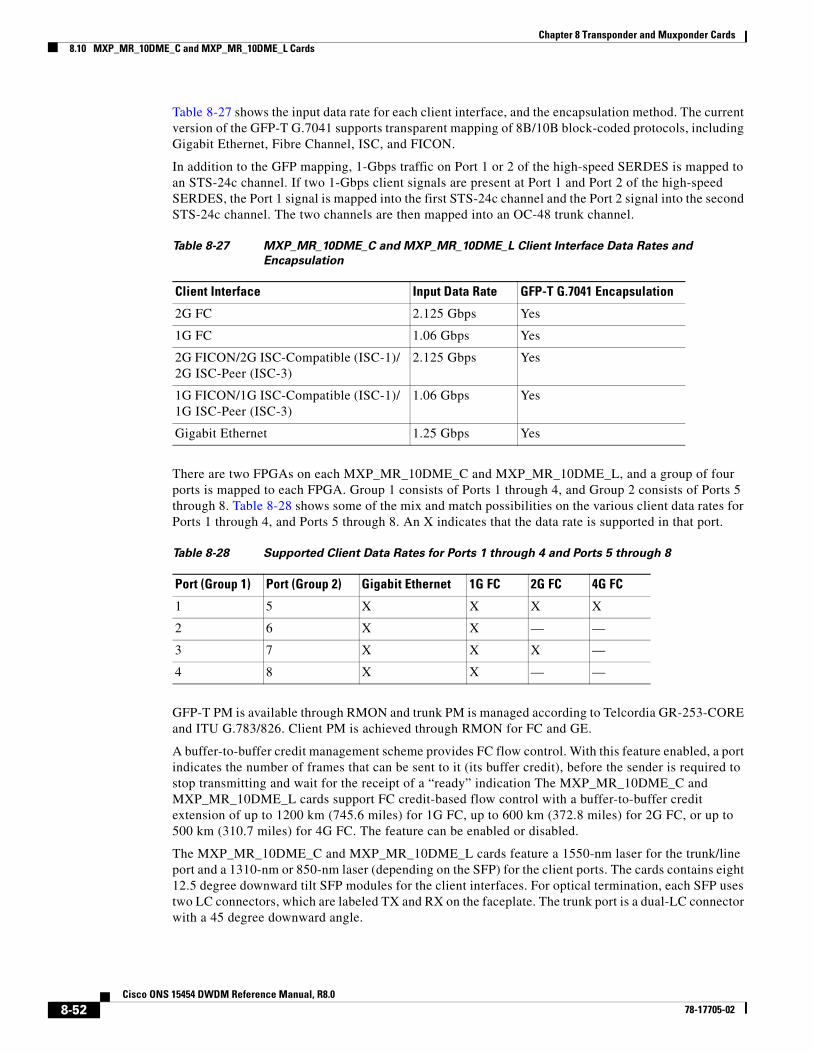
Chapter 8 Transponder and Muxponder Cards8.10 MXP_MR_10DME_C and MXP_MR_10DME_L Cards
Table 8-27 shows the input data rate for each client interface, and the encapsulation method. The current version of the GFP-T G.7041 supports transparent mapping of 8B/10B block-coded protocols, including Gigabit Ethernet, Fibre Channel, ISC, and FICON.
In addition to the GFP mapping, 1-Gbps traffic on Port 1 or 2 of the high-speed SERDES is mapped to an STS-24c channel. If two 1-Gbps client signals are present at Port 1 and Port 2 of the high-speed SERDES, the Port 1 signal is mapped into the first STS-24c channel and the Port 2 signal into the second STS-24c channel. The two channels are then mapped into an OC-48 trunk channel.
There are two FPGAs on each MXP_MR_10DME_C and MXP_MR_10DME_L, and a group of four ports is mapped to each FPGA. Group 1 consists of Ports 1 through 4, and Group 2 consists of Ports 5 through 8. Table 8-28 shows some of the mix and match possibilities on the various client data rates for Ports 1 through 4, and Ports 5 through 8. An X indicates that the data rate is supported in that port.
GFP-T PM is available through RMON and trunk PM is managed according to Telcordia GR-253-CORE and ITU G.783/826. Client PM is achieved through RMON for FC and GE.
A buffer-to-buffer credit management scheme provides FC flow control. With this feature enabled, a port indicates the number of frames that can be sent to it (its buffer credit), before the sender is required to stop transmitting and wait for the receipt of a “ready” indication The MXP_MR_10DME_C and MXP_MR_10DME_L cards support FC credit-based flow control with a buffer-to-buffer credit extension of up to 1200 km (745.6 miles) for 1G FC, up to 600 km (372.8 miles) for 2G FC, or up to 500 km (310.7 miles) for 4G FC. The feature can be enabled or disabled.
The MXP_MR_10DME_C and MXP_MR_10DME_L cards feature a 1550-nm laser for the trunk/line port and a 1310-nm or 850-nm laser (depending on the SFP) for the client ports. The cards contains eight 12.5 degree downward tilt SFP modules for the client interfaces. For optical termination, each SFP uses two LC connectors, which are labeled TX and RX on the faceplate. The trunk port is a dual-LC connector with a 45 degree downward angle.
Table 8-27 MXP_MR_10DME_C and MXP_MR_10DME_L Client Interface Data Rates and
Encapsulation
Client Interface Input Data Rate GFP-T G.7041 Encapsulation
2G FC 2.125 Gbps Yes
1G FC 1.06 Gbps Yes
2G FICON/2G ISC-Compatible (ISC-1)/ 2G ISC-Peer (ISC-3)
2.125 Gbps Yes
1G FICON/1G ISC-Compatible (ISC-1)/ 1G ISC-Peer (ISC-3)
1.06 Gbps Yes
Gigabit Ethernet 1.25 Gbps Yes
Table 8-28 Supported Client Data Rates for Ports 1 through 4 and Ports 5 through 8
Port (Group 1) Port (Group 2) Gigabit Ethernet 1G FC 2G FC 4G FC
1 5 X X X X
2 6 X X — —
3 7 X X X —
4 8 X X — —
8-52Cisco ONS 15454 DWDM Reference Manual, R8.0
78-17705-02
Chapter 8 Transponder and Muxponder Cards8.10.1 Key Features
The throughput of the MXP_MR_10DME_C and MXP_MR_10DME_L cards is affected by the following parameters:
• Distance extension—If distance extension is enabled on the card, it provides more throughput but more latency. If distance extension is disabled on the card, the buffer to buffer credits on the storage switch affects the throughput; higher the buffer to buffer credits higher is the throughput.
Note For each link to operate at the maximum throughput, it requires a minimum number of buffer credits to be available on the devices which the link connects to. The number of buffer credits required is a function of the distance between the storage switch extension ports and the link bandwidth, that is, 1G, 2G, or 4G. These buffer credits are provided by either the storage switch (if distance extension is disabled) or by both the storage switch and the card (if distance extension is enabled).
• Forward Error Correction (FEC)—If Enhanced FEC (E-FEC) is enabled on the trunk port of the card, the throughout is significantly reduced in comparison to standard FEC being set on the trunk port.
Note If distance extension is enabled on the card, the FEC status does not usually affect the throughput of the card.
• Payload size—The throughput of the card decreases with decrease in payload size.
The resultant throughput of the card is usually the combined effect of the above parameters.
8.10.1 Key FeaturesThe MXP_MR_10DME_C and MXP_MR_10DME_L cards have the following high-level features:
• Onboard E-FEC processor: The processor supports both standard RS (specified in ITU-T G.709) and E-FEC, which allows an improved gain on trunk interfaces with a resultant extension of the transmission range on these interfaces. The E-FEC functionality increases the correction capability of the transponder to improve performance, allowing operation at a lower OSNR compared to the standard RS (237,255) correction algorithm. A new BCH algorithm implemented in E-FEC allows recovery of an input BER up to 1E-3.
• Pluggable client interface optic modules: The MXP_MR_10DME_C and MXP_MR_10DME_L cards have modular interfaces. Two types of optics modules can be plugged into the card. These include an OC-48/STM 16 SR-1 interface with a 7-km (4.3-mile) nominal range (for short range and intra-office applications) and an IR-1 interface with a range up to 40 km (24.9 miles). SR-1 is defined in Telcordia GR-253-CORE and in I-16 (ITU-T G.957). IR-1 is defined in Telcordia GR-253-CORE and in S-16-1 (ITU-T G.957).
• Y-cable protection: Supports Y-cable protection between the same card type only, on ports with the same port number and signal rate. See the “8.13.1 Y-Cable Protection” section on page 8-74 for more detailed information.
• High level provisioning support: The cards are initially provisioned using Cisco MetroPlanner software. Subsequently, the card can be monitored and provisioned using CTC software.
• ALS: A safety mechanism used in the event of a fiber cut. For details regarding ALS provisioning for the MXP_MR_10DME_C and MXP_MR_10DME_L cards, refer to the Cisco ONS 15454 DWDM Procedure Guide.
8-53Cisco ONS 15454 DWDM Reference Manual, R8.0
78-17705-02
Chapter 8 Transponder and Muxponder Cards8.10.2 Faceplate
• Link monitoring and management: The cards use standard OC-48 OH bytes to monitor and manage incoming interfaces. The cards pass the incoming SDH/SONET data stream and its OH bytes transparently.
• Control of layered SONET/SDH transport overhead: The cards are provisionable to terminate regenerator section overhead. This is used to eliminate forwarding of unneeded layer overhead. It can help reduce the number of alarms and help isolate faults in the network.
• Automatic timing source synchronization: The MXP_MR_10DME_C and MXP_MR_10DME_L cards normally synchronize from the TCC2/TCC2P card. If for some reason, such as maintenance or upgrade activity, the TCC2/TCC2P is not available, the cards automatically synchronize to one of the input client interface clocks.
Note MXP_MR_10DME_C and MXP_MR_10DME_L cards cannot be used for line timing.
• Configurable squelching policy: The cards can be configured to squelch the client interface output if there is LOS at the DWDM receiver or if there is a remote fault. In the event of a remote fault, the card manages MS-AIS insertion.
• The cards are tunable across the full C band (MXP_MR_10DME_C) or full L band (MXP_MR_10DME_L), thus eliminating the need to use different versions of each card to provide tunability across specific wavelengths in a band.
• You can provision a string (port name) for each fiber channel/FICON interface on the MXP_MR_10DME_C and MXP_MR_10DME_L cards, which allows the MDS Fabric Manager to create a link association between that SAN port and a SAN port on a Cisco MDS 9000 switch.
8.10.2 FaceplateFigure 8-23 shows the MXP_MR_10DME_C and MXP_MR_10DME_L faceplates and block diagram.
8-54Cisco ONS 15454 DWDM Reference Manual, R8.0
78-17705-02
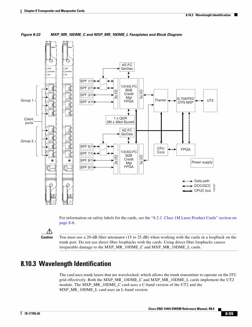
Chapter 8 Transponder and Muxponder Cards8.10.3 Wavelength Identification
Figure 8-23 MXP_MR_10DME_C and MXP_MR_10DME_L Faceplates and Block Diagram
For information on safety labels for the cards, see the “8.2.2 Class 1M Laser Product Cards” section on page 8-6.
Caution You must use a 20-dB fiber attenuator (15 to 25 dB) when working with the cards in a loopback on the trunk port. Do not use direct fiber loopbacks with the cards. Using direct fiber loopbacks causes irreparable damage to the MXP_MR_10DME_C and MXP_MR_10DME_L cards.
8.10.3 Wavelength IdentificationThe card uses trunk lasers that are wavelocked, which allows the trunk transmitter to operate on the ITU grid effectively. Both the MXP_MR_10DME_C and MXP_MR_10DME_L cards implement the UT2 module. The MXP_MR_10DME_C card uses a C-band version of the UT2 and the MXP_MR_10DME_L card uses an L-band version.
10DME-C
FAIL
ACT/STBY
SF
1457
67
RXTX1
RXTX2
RXTX3
RXTX4
RXTX1
RXTX2
RXTX3
RXTX4
DWDM
RXTX
10DME-L
FAIL
ACT/STBY
SF
RXTX1
RXTX2
RXTX3
RXTX4
RXTX1
RXTX2
RXTX3
RXTX4
DWDM
RXTX
SPF 1/1
4G FCSerDes
1 x QDR2M x 36bit Burst4
1/2/4G-FCB2B
CreditMgt
FPGA Framer G.709/FECOTN MXP UT2
Data path
5x I/
O
5x I/
O
SPF 2/1
SPF 3/1
CPUCore
FPGA
Power supply
DCC/GCCCPUC bus
SPF 4/1
SPF 6/1
4G FCSerDes
1/2/4G-FCB2B
CreditMgt
FPGA
5x I/
O
5x I/
O
SPF 7/1
SPF 8/1
SPF 9/1
Clientports
Group 1
Group 2
8-55Cisco ONS 15454 DWDM Reference Manual, R8.0
78-17705-02

Chapter 8 Transponder and Muxponder Cards8.10.3 Wavelength Identification
Table 8-29 describes the required trunk transmit laser wavelengths for the MXP_MR_10DME_C card. The laser is tunable over 82 wavelengths in the C band at 50-GHz spacing on the ITU grid.
Table 8-29 MXP_MR_10DME_C Trunk Wavelengths
Channel Number
Frequency (THz)
Wavelength (nm)
Channel Number
Frequency (THz)
Wavelength (nm)
1 196.00 1529.55 42 193.95 1545.72
2 195.95 1529.94 43 193.90 1546.119
3 195.90 1530.334 44 193.85 1546.518
4 195.85 1530.725 45 193.80 1546.917
5 195.80 1531.116 46 193.75 1547.316
6 195.75 1531.507 47 193.70 1547.715
7 195.70 1531.898 48 193.65 1548.115
8 195.65 1532.290 49 193.60 1548.515
9 195.60 1532.681 50 193.55 1548.915
10 195.55 1533.073 51 193.50 1549.32
11 195.50 1533.47 52 193.45 1549.71
12 195.45 1533.86 53 193.40 1550.116
13 195.40 1534.250 54 193.35 1550.517
14 195.35 1534.643 55 193.30 1550.918
15 195.30 1535.036 56 193.25 1551.319
16 195.25 1535.429 57 193.20 1551.721
17 195.20 1535.822 58 193.15 1552.122
18 195.15 1536.216 59 193.10 1552.524
19 195.10 1536.609 60 193.05 1552.926
20 195.05 1537.003 61 193.00 1553.33
21 195.00 1537.40 62 192.95 1553.73
22 194.95 1537.79 63 192.90 1554.134
23 194.90 1538.186 64 192.85 1554.537
24 194.85 1538.581 65 192.80 1554.940
25 194.80 1538.976 66 192.75 1555.343
26 194.75 1539.371 67 192.70 1555.747
27 194.70 1539.766 68 192.65 1556.151
28 194.65 1540.162 69 192.60 1556.555
29 194.60 1540.557 70 192.55 1556.959
30 194.55 1540.953 71 192.50 1557.36
31 194.50 1541.35 72 192.45 1557.77
32 194.45 1541.75 73 192.40 1558.173
33 194.40 1542.142 74 192.35 1558.578
8-56Cisco ONS 15454 DWDM Reference Manual, R8.0
78-17705-02
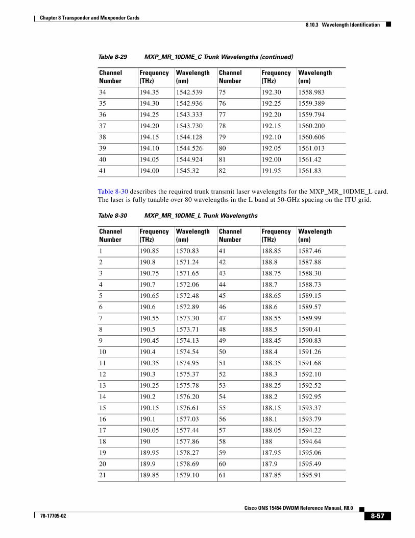
Chapter 8 Transponder and Muxponder Cards8.10.3 Wavelength Identification
Table 8-30 describes the required trunk transmit laser wavelengths for the MXP_MR_10DME_L card. The laser is fully tunable over 80 wavelengths in the L band at 50-GHz spacing on the ITU grid.
34 194.35 1542.539 75 192.30 1558.983
35 194.30 1542.936 76 192.25 1559.389
36 194.25 1543.333 77 192.20 1559.794
37 194.20 1543.730 78 192.15 1560.200
38 194.15 1544.128 79 192.10 1560.606
39 194.10 1544.526 80 192.05 1561.013
40 194.05 1544.924 81 192.00 1561.42
41 194.00 1545.32 82 191.95 1561.83
Table 8-29 MXP_MR_10DME_C Trunk Wavelengths (continued)
Channel Number
Frequency (THz)
Wavelength (nm)
Channel Number
Frequency (THz)
Wavelength (nm)
Table 8-30 MXP_MR_10DME_L Trunk Wavelengths
Channel Number
Frequency (THz)
Wavelength (nm)
Channel Number
Frequency (THz)
Wavelength (nm)
1 190.85 1570.83 41 188.85 1587.46
2 190.8 1571.24 42 188.8 1587.88
3 190.75 1571.65 43 188.75 1588.30
4 190.7 1572.06 44 188.7 1588.73
5 190.65 1572.48 45 188.65 1589.15
6 190.6 1572.89 46 188.6 1589.57
7 190.55 1573.30 47 188.55 1589.99
8 190.5 1573.71 48 188.5 1590.41
9 190.45 1574.13 49 188.45 1590.83
10 190.4 1574.54 50 188.4 1591.26
11 190.35 1574.95 51 188.35 1591.68
12 190.3 1575.37 52 188.3 1592.10
13 190.25 1575.78 53 188.25 1592.52
14 190.2 1576.20 54 188.2 1592.95
15 190.15 1576.61 55 188.15 1593.37
16 190.1 1577.03 56 188.1 1593.79
17 190.05 1577.44 57 188.05 1594.22
18 190 1577.86 58 188 1594.64
19 189.95 1578.27 59 187.95 1595.06
20 189.9 1578.69 60 187.9 1595.49
21 189.85 1579.10 61 187.85 1595.91
8-57Cisco ONS 15454 DWDM Reference Manual, R8.0
78-17705-02
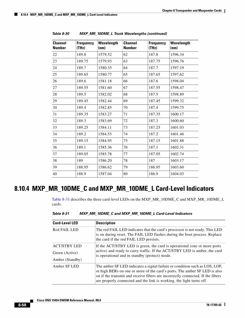
Chapter 8 Transponder and Muxponder Cards8.10.4 MXP_MR_10DME_C and MXP_MR_10DME_L Card-Level Indicators
8.10.4 MXP_MR_10DME_C and MXP_MR_10DME_L Card-Level IndicatorsTable 8-31 describes the three card-level LEDs on the MXP_MR_10DME_C and MXP_MR_10DME_L cards.
22 189.8 1579.52 62 187.8 1596.34
23 189.75 1579.93 63 187.75 1596.76
24 189.7 1580.35 64 187.7 1597.19
25 189.65 1580.77 65 187.65 1597.62
26 189.6 1581.18 66 187.6 1598.04
27 189.55 1581.60 67 187.55 1598.47
28 189.5 1582.02 68 187.5 1598.89
29 189.45 1582.44 69 187.45 1599.32
30 189.4 1582.85 70 187.4 1599.75
31 189.35 1583.27 71 187.35 1600.17
32 189.3 1583.69 72 187.3 1600.60
33 189.25 1584.11 73 187.25 1601.03
34 189.2 1584.53 74 187.2 1601.46
35 189.15 1584.95 75 187.15 1601.88
36 189.1 1585.36 76 187.1 1602.31
37 189.05 1585.78 77 187.05 1602.74
38 189 1586.20 78 187 1603.17
39 188.95 1586.62 79 186.95 1603.60
40 188.9 1587.04 80 186.9 1604.03
Table 8-30 MXP_MR_10DME_L Trunk Wavelengths (continued)
Channel Number
Frequency (THz)
Wavelength (nm)
Channel Number
Frequency (THz)
Wavelength (nm)
Table 8-31 MXP_MR_10DME_C and MXP_MR_10DME_L Card-Level Indicators
Card-Level LED Description
Red FAIL LED The red FAIL LED indicates that the card’s processor is not ready. This LED is on during reset. The FAIL LED flashes during the boot process. Replace the card if the red FAIL LED persists.
ACT/STBY LED
Green (Active)
Amber (Standby)
If the ACT/STBY LED is green, the card is operational (one or more ports active) and ready to carry traffic. If the ACT/STBY LED is amber, the card is operational and in standby (protect) mode.
Amber SF LED The amber SF LED indicates a signal failure or condition such as LOS, LOF, or high BERs on one or more of the card’s ports. The amber SF LED is also on if the transmit and receive fibers are incorrectly connected. If the fibers are properly connected and the link is working, the light turns off.
8-58Cisco ONS 15454 DWDM Reference Manual, R8.0
78-17705-02
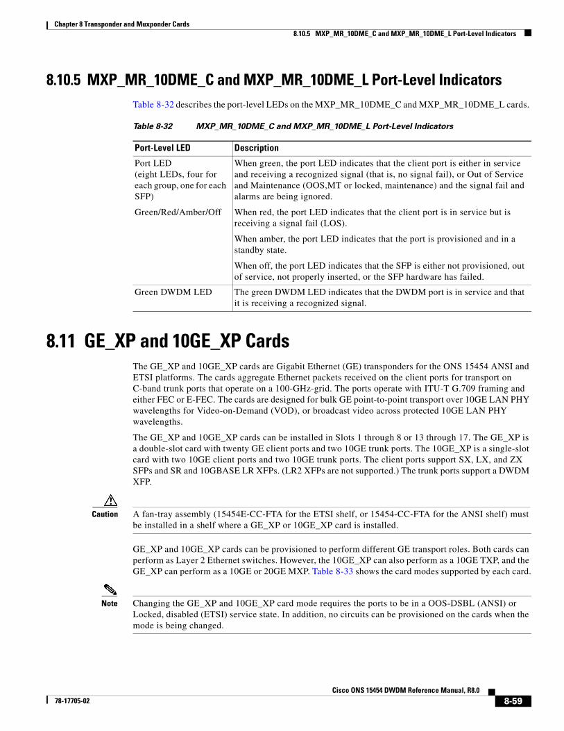
Chapter 8 Transponder and Muxponder Cards8.10.5 MXP_MR_10DME_C and MXP_MR_10DME_L Port-Level Indicators
8.10.5 MXP_MR_10DME_C and MXP_MR_10DME_L Port-Level IndicatorsTable 8-32 describes the port-level LEDs on the MXP_MR_10DME_C and MXP_MR_10DME_L cards.
8.11 GE_XP and 10GE_XP CardsThe GE_XP and 10GE_XP cards are Gigabit Ethernet (GE) transponders for the ONS 15454 ANSI and ETSI platforms. The cards aggregate Ethernet packets received on the client ports for transport on C-band trunk ports that operate on a 100-GHz-grid. The ports operate with ITU-T G.709 framing and either FEC or E-FEC. The cards are designed for bulk GE point-to-point transport over 10GE LAN PHY wavelengths for Video-on-Demand (VOD), or broadcast video across protected 10GE LAN PHY wavelengths.
The GE_XP and 10GE_XP cards can be installed in Slots 1 through 8 or 13 through 17. The GE_XP is a double-slot card with twenty GE client ports and two 10GE trunk ports. The 10GE_XP is a single-slot card with two 10GE client ports and two 10GE trunk ports. The client ports support SX, LX, and ZX SFPs and SR and 10GBASE LR XFPs. (LR2 XFPs are not supported.) The trunk ports support a DWDM XFP.
Caution A fan-tray assembly (15454E-CC-FTA for the ETSI shelf, or 15454-CC-FTA for the ANSI shelf) must be installed in a shelf where a GE_XP or 10GE_XP card is installed.
GE_XP and 10GE_XP cards can be provisioned to perform different GE transport roles. Both cards can perform as Layer 2 Ethernet switches. However, the 10GE_XP can also perform as a 10GE TXP, and the GE_XP can perform as a 10GE or 20GE MXP. Table 8-33 shows the card modes supported by each card.
Note Changing the GE_XP and 10GE_XP card mode requires the ports to be in a OOS-DSBL (ANSI) or Locked, disabled (ETSI) service state. In addition, no circuits can be provisioned on the cards when the mode is being changed.
Table 8-32 MXP_MR_10DME_C and MXP_MR_10DME_L Port-Level Indicators
Port-Level LED Description
Port LED(eight LEDs, four for each group, one for each SFP)
Green/Red/Amber/Off
When green, the port LED indicates that the client port is either in service and receiving a recognized signal (that is, no signal fail), or Out of Service and Maintenance (OOS,MT or locked, maintenance) and the signal fail and alarms are being ignored.
When red, the port LED indicates that the client port is in service but is receiving a signal fail (LOS).
When amber, the port LED indicates that the port is provisioned and in a standby state.
When off, the port LED indicates that the SFP is either not provisioned, out of service, not properly inserted, or the SFP hardware has failed.
Green DWDM LED The green DWDM LED indicates that the DWDM port is in service and that it is receiving a recognized signal.
8-59Cisco ONS 15454 DWDM Reference Manual, R8.0
78-17705-02
Chapter 8 Transponder and Muxponder Cards8.11.1 Key Features
8.11.1 Key FeaturesThe GE_XP and 10GE_XP cards have the following high-level features:
• GE MXP, TXP, and Layer 2 switch capability over the ONS 15454 DWDM platform.
• Interoperable with TXP_MR_10E and TXP_MR_10E_C cards. Also interoperable with Cisco Catalyst 6500 and Cisco 7600 series GE and 10GE interfaces.
• Compatible with the ONS 15454 ANSI high-density shelf assembly, the ETSI ONS 15454 shelf assembly, and the ETSI ONS 15454 high-density shelf assembly. Compatible with TCC2 and TCC2P cards.
• Ports: The GE_XP has twenty GE client ports and two 10GE trunk ports. The 10GE_XP has two 10GE client ports and two 10GE trunk ports. The client GE signals are mapped into an ITU-T G.709 OTU2 signal using standard ITU-T G.709 multiplexing.
• FEC and E-FEC: ITU-T G.709 framing with standard Reed-Soloman (RS) (255,237) FEC. Performance monitoring and ITU-T G.709 Optical Data Unit (ODU) synchronous and asynchronous mapping. E-FEC with ITU-T G.709 ODU and 2.7 Gbps with greater than 8 dB coding gain.
• Broadcast drop-and-continue capability for VOD and broadcast video applications.
• Layer 2 switch mode provides VLAN translation, QinQ, ingress CoS egress QoS, Fast Ethernet protection switching, and other Layer 2 Ethernet services.
• IEEE 802.3 frame format supported for 10GE interfaces. The minimum frame size is 64 bytes. The maximum frame size is user-provisionable.
• MAC learning capability in Layer 2 switch mode.
• Configurable service provider VLANs (SVLANs) and customer VLANs (CVLANs).
• In Layer 2 switch mode, ports can be provisioned as network-to-network interfaces (NNIs) or user-network interfaces (UNIs) to facilitate service provider to customer traffic management.
• When a port is in UNI mode, tagging can be configured as transparent or selective. In transparent mode, only SVLANs in the node’s VLAN database can be configured. In selective mode, a CVLAN- to-SVLAN relationship can be defined.
• Layer 2 VLAN port mapping allows the cards to be configured as multiple GE TXPs and MXPs.
• Protection through Y-cable protection schemes.
Table 8-33 GE_XP and 10GE_XP Card Modes
Card Mode Card Description
Layer 2 Ethernet switch
GE_XP
10GE_XP
Provides capability to switch between any client port traffic and any trunk port. Supported Ethernet protocols and services include QoS (Quality of Service), CoS (Class of Service), QinQ, MAC learning, service provider VLANs (SVLANs), and other Ethernet switch services.
10GE TXP 10GE_XP Provides a point-to-point application in which each 10 Gigabit Ethernet client port is mapped to a 10 Gigabit Ethernet trunk port.
10GE MXP
20GE MXP
GE_XP Provides the ability to multiplex any combination of the card’s twenty GE client ports to one or both of its 10GE trunk ports. The card can be provisioned as a single MXP with twenty GE client ports or as two MXPs with ten GE client ports and one trunk port.
8-60Cisco ONS 15454 DWDM Reference Manual, R8.0
78-17705-02
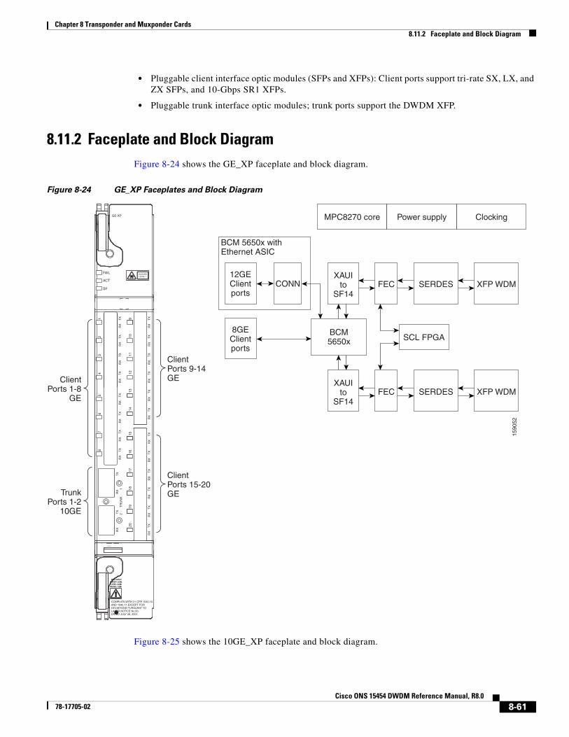
Chapter 8 Transponder and Muxponder Cards8.11.2 Faceplate and Block Diagram
• Pluggable client interface optic modules (SFPs and XFPs): Client ports support tri-rate SX, LX, and ZX SFPs, and 10-Gbps SR1 XFPs.
• Pluggable trunk interface optic modules; trunk ports support the DWDM XFP.
8.11.2 Faceplate and Block DiagramFigure 8-24 shows the GE_XP faceplate and block diagram.
Figure 8-24 GE_XP Faceplates and Block Diagram
Figure 8-25 shows the 10GE_XP faceplate and block diagram.
FAIL
ACT
SF
GE-XP
1 TX
RX
2 TX
RX
3 TX
RX
4 TX
RX
5 TX
RX
6 TX
RX
7 TX
RX
8 TX
RX
9 TX
RX
10 TX
RX
11 TX
RX
12 TX
RX
13 TX
RX
14 TX
RX
15 TX
RX
16 TX
RX
17 TX
RX
18 TX
RX
19 TX
RX
20 TX
RX
TX
RX
2
T
RU
NK
1
CONSOLE
T2 T1
TX
RX
!!
MAX INPUTPOWER LEVELCLIENT: +3dBmTRUNK: +1dBm
HAZARDLEVEL 1
1590
52
12GEClientports
CONN
8GEClientports
XAUIto
SF14
XAUIto
SF14
FEC SERDES XFP WDM
FEC SERDES XFP WDM
MPC8270 core Power supply Clocking
BCM5650x SCL FPGA
COMPLIES WITH 21 CFR 1040.10AND 1040.11 EXCEPT FORDEVIATIONS PURSUANT TOLASER NOTICE No.50,DATED JULY 26, 2001
ClientPorts 9-14GEClient
Ports 1-8GE
ClientPorts 15-20GETrunk
Ports 1-210GE
BCM 5650x withEthernet ASIC
8-61Cisco ONS 15454 DWDM Reference Manual, R8.0
78-17705-02
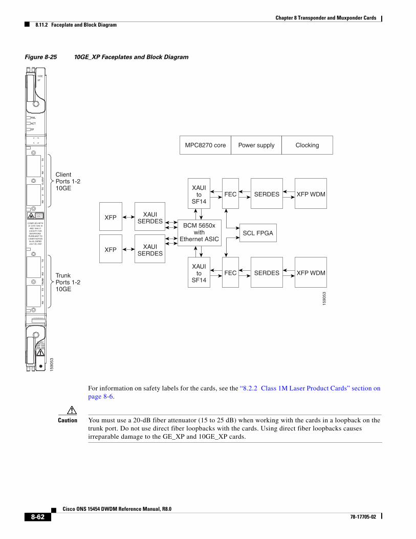
Chapter 8 Transponder and Muxponder Cards8.11.2 Faceplate and Block Diagram
Figure 8-25 10GE_XP Faceplates and Block Diagram
For information on safety labels for the cards, see the “8.2.2 Class 1M Laser Product Cards” section on page 8-6.
Caution You must use a 20-dB fiber attenuator (15 to 25 dB) when working with the cards in a loopback on the trunk port. Do not use direct fiber loopbacks with the cards. Using direct fiber loopbacks causes irreparable damage to the GE_XP and 10GE_XP cards.
!
MAX INPUTPOWER LEVELCLIENT: +3dBmTRUNK: +1dBm
HAZARDLEVEL 1
10GE
XP
RX
2
T
X
TR
UN
K
RX
1
T
XR
X
2
TX
C
LIE
NT
R
X
1
TX
COMPLIES WITH21 CFR 1040.10
AND 1040.11EXCEPT FORDEVIATIONS
PURSUANT TOLASER NOTICENo.50, DATED JULY 26, 2001
FAIL
ACT
SF
CONSOLE
1590
53
1590
53
XFP XAUISERDES
XFP XAUISERDES
XAUIto
SF14
XAUIto
SF14
FEC SERDES XFP WDM
FEC SERDES XFP WDM
MPC8270 core Power supply Clocking
BCM 5650xwith
Ethernet ASICSCL FPGA
ClientPorts 1-210GE
TrunkPorts 1-210GE
8-62Cisco ONS 15454 DWDM Reference Manual, R8.0
78-17705-02
Chapter 8 Transponder and Muxponder Cards8.11.3 Client Interface
8.11.3 Client InterfaceThe client interface is implemented with separately orderable SFP or XFP modules. The client interfaces support the following tri-rate SFPs and XFPs using dual LC connectors and multi-mode fiber:
• SFP- GE/1G-FC/2G-FC - 850 nm - MM - LC (PID ONS-SE-G2F-SX)
• SFP - GE/1G-FC/2G-FC 1300 nm - SM - LC (PID ONS-SE-G2F-LX)
• SFP - GE/1G-FC/2G-FC 1300 nm - SM - LC (PID ONS-SE-G2F-ZX)
• SFP - 10/100/1000Base-T - Copper (PID ONS-SE-ZE-EL) Intra office up to 100;Cable: RJ45 STP CAT5, CAT5E, and CAT6
The client interfaces support the following dual-rate XFP using dual LC connectors and single-mode fiber:
• XFP - OC-192/STM-64/10GE/10-FC/OTU2 - 1310 SR - SM LC (PID: ONS-XC-10G-S1)
Note On GE_XP card, the copper Pluggable Port Module (PPM) interface can auto-negotiate and carry traffic only when the peer interface operates at 1000 Mbps.
8.11.4 DWDM Trunk Interface The GE_XP and 10GE_XP cards have two 10GE trunk ports operating at 10GE (10.3125 Gbps) or 10GE into OTU2 (nonstandard 10.0957 Gbps). The ports are compliant with ITU-T G.707, ITU-T G.709, and Telcordia GR-253-CORE standards. The ports are capable of carrying C band and L band wavelengths through insertion of DWDM XFPs. Forty channels are available in the 1550-nm C band 100-GHz ITU grid, and forty channels are available in the L band.
The maximum system reach in filterless applications without the use of optical amplification or regenerators is nominally rated at 23 dB over C-SMF fiber. This rating is not a product specification, but is given for informational purposes. It is subject to change.
8.11.5 Configuration ManagementThe GE_XP and 10GE_XP cards support the following configuration management parameters:
• Port name—User-assigned text string.
• Admin State/Service State—Administrative and service states to manage and view port status.
• MTU—Provisionable maximum transfer unit (MTU) to set the maximum number of bytes per frames accepted on the port.
• Mode—Provisional port mode, either Autonegotiation or the port speed.
• Flow Control—Flow control according to IEEE 802.1x pause frame specification can be enabled or disabled for TX and RX ports.
• Bandwidth—Provisionable maximum bandwidth allowed for the port.
• Ingress CoS—Assigns a CoS value to the port from 0 (highest) to 7 (lowest) and accepts CoS of incoming frames.
• Egress QoS—Defines the QoS capabilities at the egress port.
8-63Cisco ONS 15454 DWDM Reference Manual, R8.0
78-17705-02
Chapter 8 Transponder and Muxponder Cards8.11.6 Security
• NIM—Defines the port network interface management type based on Metro Ethernet Forum specifications. Ports can be defined as UNI (user-to-network interface) or NNI (network-to-network interface).
• MAC Learning—MAC Address learning to facilitate switch processing.
• VLAN tagging provided according to the IEEE 802.1Q standard.
Note When the GE_XP and 10GE_XP cards are provisioned in a MXP or TXP mode, only the following parameters are available: Port Name, State, MTU, Mode, Flow control, and Bandwidth.
8.11.6 SecurityGE_XP and 10GE_XP card ports can be provisioned to block traffic from a user-defined set of MAC addresses. The remaining traffic is normally switched. You can manually specify the set of blocked MAC addresses for each port. Each port of the card can receive traffic from a limited predefined set of MAC addresses. The remaining traffic will be dropped. This capability is a subset of the Cisco IOS “Port Security” feature.
8.11.7 Y-Cable ProtectionThe GE_XP card supports Y-cable protection when it is provisioned in 10GE or 20GE MXP card mode. The 10GE_XP supports Y-cable protection when it is provisioned in 10GE TXP card mode. Two cards can be joined in a Y-cable protection group with one card assigned as the working card and the other defined as the protection card. This protection mechanism provides redundant bidirectional paths. See the “8.13.1 Y-Cable Protection” section on page 8-74 for more detailed information. The Y-protection mechanism is provisionable and can be set ON or OFF (OFF is the default mode). When a signal fault is detected (LOS, LOF, SD, or SF on the DWDM receiver port in the case of ITU-T G.709 mode) the protection mechanism software automatically switches between paths.
8.11.8 Layer 2 Over DWDM ProtectionWhen the GE_XP and 10GE_XP are in Layer 2 (L2) over DWDM card mode, protection is handled by the hardware at the Layer 1 and Layer 2 levels. Fault detection and failure propagation is communicated through the ITU-T G.709 frame overhead bytes. For protected VLANs, traffic is flooded around the 10GE DWDM ring. To set up the Layer 2 protection, you identify a node and the GE_XP or 10GE_XP port that is to serve as the master node and port for the VLAN ring on the card view Provisioning > Protection tab (Figure 8-26). If a failure occurs, the node and port are responsible for opening and closing VLAN loops.
Note The Forced option in the Protection drop-down list converts all the SVLANs to protected SVLANs irrespective of the SVLAN protection configuration in the SVLAN database. This is applicable to a point-to-point linear topology. The SVLAN protection must be forced to move all SVLANs, including protected and unprotected SVLANs, to the protect path irrespective of provisioned SVLAN attributes.
A FAPS switchover happens in the following failure scenarios:
• DWDM line failures caused by a fiber cut
8-64Cisco ONS 15454 DWDM Reference Manual, R8.0
78-17705-02
Chapter 8 Transponder and Muxponder Cards8.11.8 Layer 2 Over DWDM Protection
• Unidirectional failure in the DWDM network caused by a fiber cut
• Fiber pull on the master card trunk port followed by a hard reset on the master card
• Hard reset on the master card
• Hard reset on the slave card
• An OTN failure is detected (LOS, OTUK-LOF, OTUK-LOM, or OTUK-LOM on the DWDM receiver port in the case of ITU-T G.709 mode)
• Trunk ports are moved to OOS,DSBLD (Locked,disabled) state
• Improper removal of XFPs
A FAPS switchover does not happen in the following scenarios:
• Slave card trunk port in OOS,DSBLD (Locked,disabled) state followed by a hard reset of the slave card
• OTN alarms raised on the slave card trunk port followed by a hard reset of the slave card
• Dual failure in the VLAN ring caused by fiber pull on the master and slave cards and restoration of a single failure
• Dual failure in the VLAN ring caused by the trunk port of master and slave cards in OOS,DSBLD (Locked,disabled) state and restoration of a single failure by placing one trunk port in IS state
• Dual failure in the VLAN ring due to the trunk port of master and slave cards in OOS,DSBLD (Locked,disabled) state followed by a hard or soft reset of the master card
8-65Cisco ONS 15454 DWDM Reference Manual, R8.0
78-17705-02
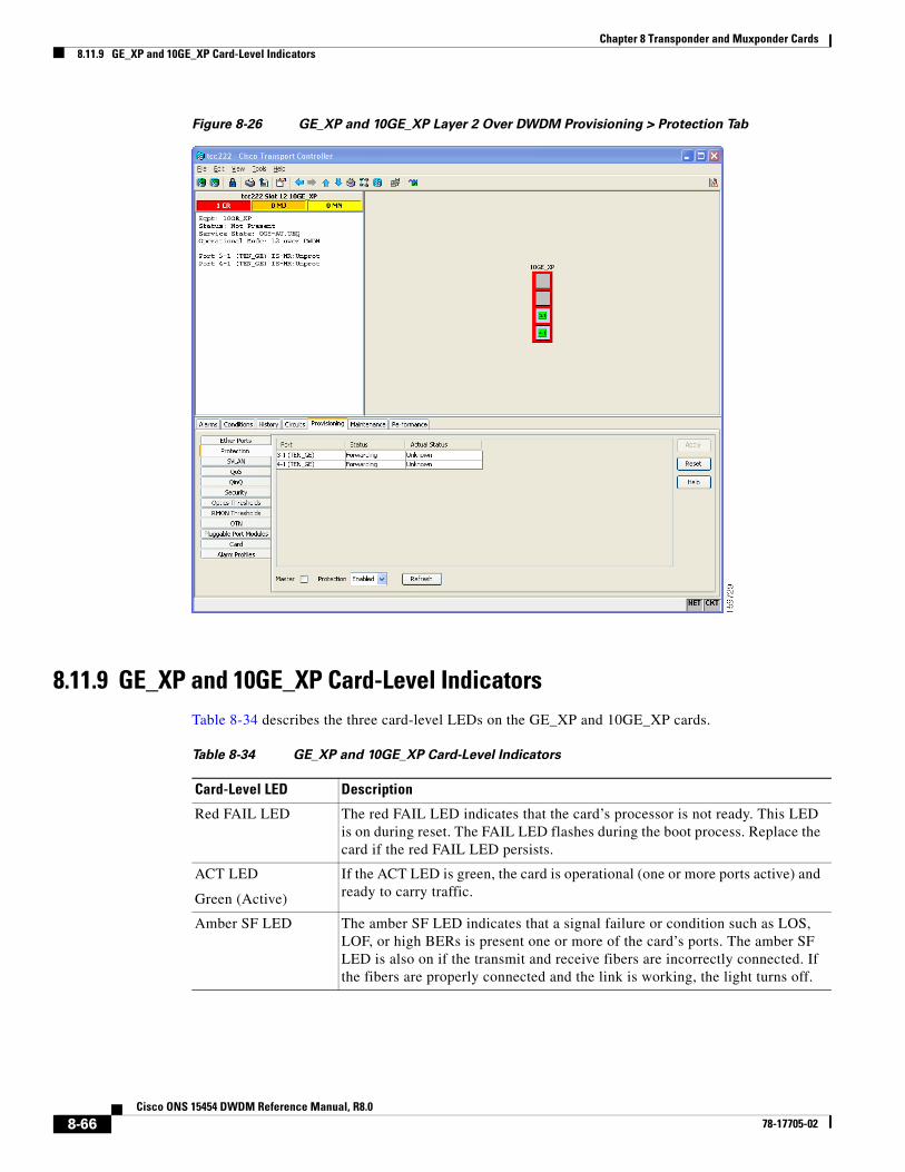
Chapter 8 Transponder and Muxponder Cards8.11.9 GE_XP and 10GE_XP Card-Level Indicators
Figure 8-26 GE_XP and 10GE_XP Layer 2 Over DWDM Provisioning > Protection Tab
8.11.9 GE_XP and 10GE_XP Card-Level IndicatorsTable 8-34 describes the three card-level LEDs on the GE_XP and 10GE_XP cards.
Table 8-34 GE_XP and 10GE_XP Card-Level Indicators
Card-Level LED Description
Red FAIL LED The red FAIL LED indicates that the card’s processor is not ready. This LED is on during reset. The FAIL LED flashes during the boot process. Replace the card if the red FAIL LED persists.
ACT LED
Green (Active)
If the ACT LED is green, the card is operational (one or more ports active) and ready to carry traffic.
Amber SF LED The amber SF LED indicates that a signal failure or condition such as LOS, LOF, or high BERs is present one or more of the card’s ports. The amber SF LED is also on if the transmit and receive fibers are incorrectly connected. If the fibers are properly connected and the link is working, the light turns off.
8-66Cisco ONS 15454 DWDM Reference Manual, R8.0
78-17705-02
Chapter 8 Transponder and Muxponder Cards8.11.10 GE_XP and 10GE_XP Port-Level Indicators
8.11.10 GE_XP and 10GE_XP Port-Level IndicatorsTable 8-35 describes the port-level LEDs on the GE_XP and 10GE_XP cards.
8.12 ADM-10G CardThe ADM-10G card operates on ONS 15454 SONET or DWDM networks to carry optical signals and Gigabit Ethernet signals over DWDM wavelengths for transport. In a DWDM network based on Gigabit Ethernet and OC-3, OC-12, OC-48, or OC-192 SONET, the ADM-10G transports low-bit-rate SONET traffic (or tunnels SDH traffic) over DWDM by mapping Gigabit Ethernet and SONET or SDH circuits onto the same wavelength with multiple protection options.
The ADM-10G is a double-slot card that can be installed in Slots 1 through 5 or 12 through 16 in standard and high-density SONET (15454-SA-ANSI or 15454-SA-HD) shelves. Installation is supported in any of these slots.
Caution Fan-tray assembly 15454E-CC-FTA (ETSI shelf)/15454-CC-FTA (ANSI shelf) must be installed in a shelf where the ADM-10G card is installed.
The card is compliant with ITU-T G.825 and ITU-T G.783 for SDH signals. It supports concatenated and nonconcatenated AU-4 mapped STM-1, STM-4, and STM-16 signals as specified in ITU-T G.707. The card also complies with Section 5.6 of Telcordia GR-253-CORE and supports synchronous transport signal (STS) mapped OC-3, OC-12, and OC-48 signals as specified in the standard.
The client SFP and trunk XFP are compliant with interface requirements in Telcordia GR-253-CORE, ITU-T G.957 and/or ITU-T G.959.1, and IEEE 802.3.
8.12.1 Key FeaturesThe ADM-10G card has the following high-level features:
• A two-slot width
• Operates with the TCC2 or TCC2P
• Has built-in OC-192 ADM function including client, trunk, and STS cross-connect
Table 8-35 GE_XP and XP_10G Port-Level Indicators
Port-Level LED Description
Port LEDs
Green/Red/Amber/Off
Green—The client port is either in service and receiving a recognized signal (that is, no signal fail), or Out of Service and Maintenance (OOS,MT or locked, maintenance) and the signal fail and alarms are being ignored.
Red—The client port is in service but is receiving a signal fail (LOS).
Amber—The port is provisioned and in a standby state.
Off—The SFP is either not provisioned, out of service, not properly inserted, or the SFP hardware has failed.
Green DWDM LED The green DWDM LED indicates that the DWDM port is in service and receiving a recognized signal.
8-67Cisco ONS 15454 DWDM Reference Manual, R8.0
78-17705-02
Chapter 8 Transponder and Muxponder Cards8.12.2 GFP Interoperability
• Provides dual-card redundancy in path protection and 1+1 client protection schemes
• Allows creation of ADM peer groups
• Supports SONET and Gigabit Ethernet protocols on client SFPs
• Supports XFP DWDM trunk interface single wavelengths
• Supports only double-card configuration.
• Tunnels SDH signals through a SONET system, provisionable from CTC
• Returns zero bit errors when a TCC2 or TCC2P switches from active to standby or when manual or forced protection switches occur
8.12.2 GFP InteroperabilityThe ADM-10G card defaults to frame-mapped generic framing procedure (GFP-F) encapsulation that is compliant with ITU-T G.7041. This mode allows the card to operate with ONS 15310-CL, ONS 15310-MA, or ONS 15454 data cards (for example, ONS 15454 CE100T-8 or ML1000-2 cards). GFP encapsulation also allows the ADM-10G card to interoperate with other vendors’ Gigabit Ethernet interfaces that adhere to the ITU-T G.7041 standard.
8.12.3 FaceplateFigure 8-27 shows the ADM-10G faceplate.
8-68Cisco ONS 15454 DWDM Reference Manual, R8.0
78-17705-02
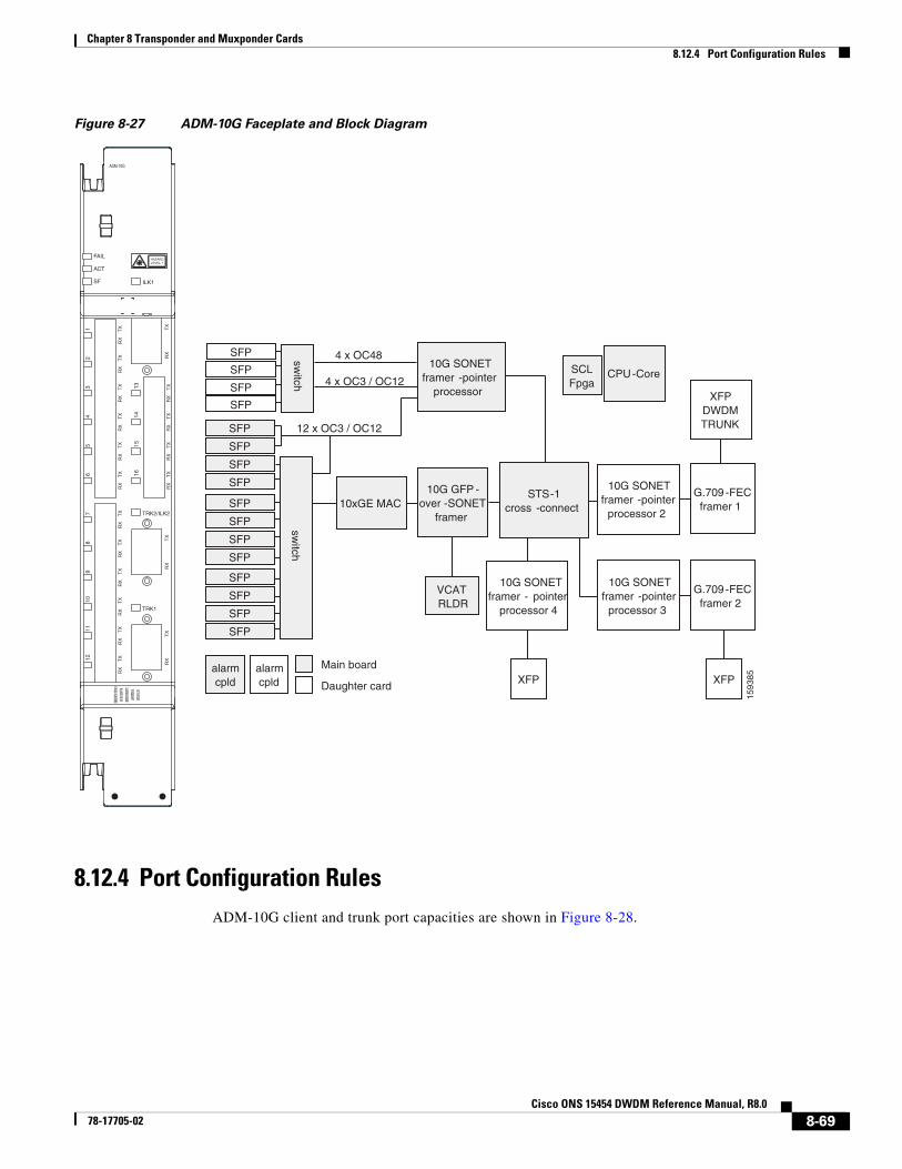
Chapter 8 Transponder and Muxponder Cards8.12.4 Port Configuration Rules
Figure 8-27 ADM-10G Faceplate and Block Diagram
8.12.4 Port Configuration RulesADM-10G client and trunk port capacities are shown in Figure 8-28.
FAIL
ACT
SF
ADM-10G
ILK1
TRK2/ILK2
TRK1
1211
109
87
65
43
21
TX
RX
TX
RX
TX
RX
1615
1413TX
RX
TX
RX
TX
RX
TX
RX
TX
RX
TX
RX
TX
RX
TX
RX
TX
RX
TX
RX
TX
RX
TX
RX
TX
RX
TX
RX
TX
RX
TX
RX
COMPLIES
WITH 21 C
FR 1040.10
AND 1040.
11 EXCEPT
FORDEVIA
TIONS PUR
SUANT TO
LASER NO
TICE No.50
,DATE
D JULY 26,
2001
1593
85XFP
SFP
SFP
SFP
SFP
SFP
SFP
SFP
SFP
SFP
SFP
SFP
SFP
10G SONETframer -pointer
processor
10xGE MAC10G GFP -
over -SONETframer
10G SONETframer -pointer
processor 2
G.709 -FECframer 1
G.709 -FECframer 2
XFPDWDMTRUNK
XFP
VCATRLDR
switch
CPU-CoreSCLFpga
alarmcpld
alarmcpld
Main board
Daughter card
4 x OC48
4 x OC3 / OC12
12 x OC3 / OC12
10G SONETframer -pointer
processor 3
10G SONETframer - pointer
processor 4
SFP
SFP
SFP
SFP
switch
STS-1cross -connect
HAZARDLEVEL 1
8-69Cisco ONS 15454 DWDM Reference Manual, R8.0
78-17705-02
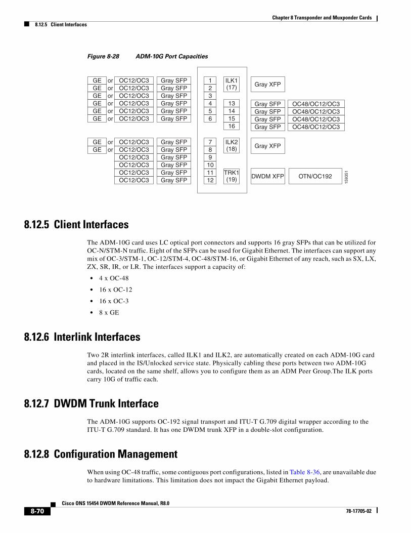
Chapter 8 Transponder and Muxponder Cards8.12.5 Client Interfaces
Figure 8-28 ADM-10G Port Capacities
8.12.5 Client InterfacesThe ADM-10G card uses LC optical port connectors and supports 16 gray SFPs that can be utilized for OC-N/STM-N traffic. Eight of the SFPs can be used for Gigabit Ethernet. The interfaces can support any mix of OC-3/STM-1, OC-12/STM-4, OC-48/STM-16, or Gigabit Ethernet of any reach, such as SX, LX, ZX, SR, IR, or LR. The interfaces support a capacity of:
• 4 x OC-48
• 16 x OC-12
• 16 x OC-3
• 8 x GE
8.12.6 Interlink InterfacesTwo 2R interlink interfaces, called ILK1 and ILK2, are automatically created on each ADM-10G card and placed in the IS/Unlocked service state. Physically cabling these ports between two ADM-10G cards, located on the same shelf, allows you to configure them as an ADM Peer Group.The ILK ports carry 10G of traffic each.
8.12.7 DWDM Trunk Interface The ADM-10G supports OC-192 signal transport and ITU-T G.709 digital wrapper according to the ITU-T G.709 standard. It has one DWDM trunk XFP in a double-slot configuration.
8.12.8 Configuration ManagementWhen using OC-48 traffic, some contiguous port configurations, listed in Table 8-36, are unavailable due to hardware limitations. This limitation does not impact the Gigabit Ethernet payload.
1593
51
GE OC12/OC3 Gray SFP 1
13141516
ILK1(17)
ILK2(18)
TRK1(19)
23456
789
101112
orGE OC12/OC3 Gray SFPorGE OC12/OC3 Gray SFPorGE OC12/OC3 OC48/OC12/OC3
OC48/OC12/OC3OC48/OC12/OC3OC48/OC12/OC3
Gray SFP Gray SFP
Gray XFP
Gray XFP
DWDM XFP OTN/OC192
Gray SFPGray SFPGray SFP
orGE OC12/OC3 Gray SFPorGE OC12/OC3 Gray SFPor
GE OC12/OC3 Gray SFPorGE OC12/OC3 Gray SFPor
OC12/OC3 Gray SFPOC12/OC3 Gray SFPOC12/OC3 Gray SFPOC12/OC3 Gray SFP
8-70Cisco ONS 15454 DWDM Reference Manual, R8.0
78-17705-02
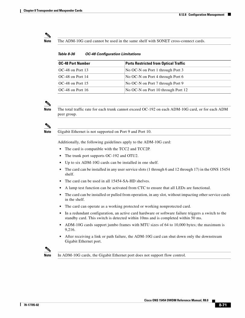
Chapter 8 Transponder and Muxponder Cards8.12.8 Configuration Management
Note The ADM-10G card cannot be used in the same shelf with SONET cross-connect cards.
Note The total traffic rate for each trunk cannot exceed OC-192 on each ADM-10G card, or for each ADM peer group.
Note Gigabit Ethernet is not supported on Port 9 and Port 10.
Additionally, the following guidelines apply to the ADM-10G card:
• The card is compatible with the TCC2 and TCC2P.
• The trunk port supports OC-192 and OTU2.
• Up to six ADM-10G cards can be installed in one shelf.
• The card can be installed in any user service slots (1 through 6 and 12 through 17) in the ONS 15454 shelf.
• The card can be used in all 15454-SA-HD shelves.
• A lamp test function can be activated from CTC to ensure that all LEDs are functional.
• The card can be installed or pulled from operation, in any slot, without impacting other service cards in the shelf.
• The card can operate as a working protected or working nonprotected card.
• In a redundant configuration, an active card hardware or software failure triggers a switch to the standby card. This switch is detected within 10ms and is completed within 50 ms.
• ADM-10G cards support jumbo frames with MTU sizes of 64 to 10,000 bytes; the maximum is 9,216.
• After receiving a link or path failure, the ADM-10G card can shut down only the downstream Gigabit Ethernet port.
Note In ADM-10G cards, the Gigabit Ethernet port does not support flow control.
Table 8-36 OC-48 Configuration Limitations
OC-48 Port Number Ports Restricted from Optical Traffic
OC-48 on Port 13 No OC-N on Port 1 through Port 3
OC-48 on Port 14 No OC-N on Port 4 through Port 6
OC-48 on Port 15 No OC-N on Port 7 through Port 9
OC-48 on Port 16 No OC-N on Port 10 through Port 12
8-71Cisco ONS 15454 DWDM Reference Manual, R8.0
78-17705-02
Chapter 8 Transponder and Muxponder Cards8.12.9 Security
8.12.9 SecurityThe ADM-10G card that an SFP or XFP is plugged into implements the Cisco Standard Security Code Check Algorithm that keys on vendor ID and serial number.
If a PPM is plugged into a port on the card but fails the security code check because it is not a Cisco PPM, a minor NON-CISCO-PPM alarm is raised.
If a PPM with a nonqualified product ID is plugged into a port on this card—that is, the PPM passes the security code as a Cisco PPM but it has not been qualified for use on the ADM-10G, a minor UNQUAL-PPM alarm is raised.
8.12.10 ProtectionThe ADM-10G supports 1+1 and SONET path protection protection architectures in compliance with Telcordia GR-253-CORE, Telcordia GR-1400-CORE, and ITU-T G.841 specifications.
8.12.10.1 Circuit Protection Schemes
The ADM-10G supports path protection circuits at the STS (high order) level and can be configured to switch based on signal degrade calculations.
The card allows open-ended path protection configurations incorporating other vendor equipment. In an open-ended path protection, you can specify one source point and two possible end points (or two possible source points and one endpoint) and the legs can include other vendor equipment. The source and end points are part of the network discovered by CTC.
For detailed information about path protection configurations and PPMNs, refer to the Cisco ONS 15454 Reference Manual.
8.12.10.2 Port Protection Schemes
For 1+1 optical client port protection, you can configure the system to use any pair of like facility interfaces that are collocated on the same ADM-10G card or on different cards. The 1+1 protection scheme can also work in a unidirectional (unprotected) way or a bidirectional (protected) way. The client port 1-16 can support 1+1 protection scheme when equipped with an OC-N card. The ADM-10G uses the same protection scheme as the OC-N card. For information on optical card protection, refer to Chap 7, Card Protection of the Cisco ONS 15454 Reference Manual.
8.12.11 ADM-10G Card-Level IndicatorsTable 8-34 describes the card-level LEDs on the ADM-10G card.
8-72Cisco ONS 15454 DWDM Reference Manual, R8.0
78-17705-02
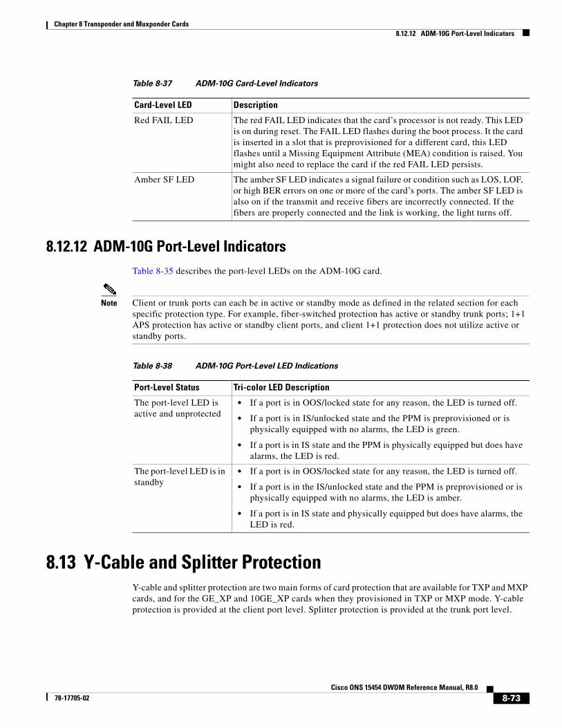
Chapter 8 Transponder and Muxponder Cards8.12.12 ADM-10G Port-Level Indicators
8.12.12 ADM-10G Port-Level IndicatorsTable 8-35 describes the port-level LEDs on the ADM-10G card.
Note Client or trunk ports can each be in active or standby mode as defined in the related section for each specific protection type. For example, fiber-switched protection has active or standby trunk ports; 1+1 APS protection has active or standby client ports, and client 1+1 protection does not utilize active or standby ports.
8.13 Y-Cable and Splitter ProtectionY-cable and splitter protection are two main forms of card protection that are available for TXP and MXP cards, and for the GE_XP and 10GE_XP cards when they provisioned in TXP or MXP mode. Y-cable protection is provided at the client port level. Splitter protection is provided at the trunk port level.
Table 8-37 ADM-10G Card-Level Indicators
Card-Level LED Description
Red FAIL LED The red FAIL LED indicates that the card’s processor is not ready. This LED is on during reset. The FAIL LED flashes during the boot process. It the card is inserted in a slot that is preprovisioned for a different card, this LED flashes until a Missing Equipment Attribute (MEA) condition is raised. You might also need to replace the card if the red FAIL LED persists.
Amber SF LED The amber SF LED indicates a signal failure or condition such as LOS, LOF, or high BER errors on one or more of the card’s ports. The amber SF LED is also on if the transmit and receive fibers are incorrectly connected. If the fibers are properly connected and the link is working, the light turns off.
Table 8-38 ADM-10G Port-Level LED Indications
Port-Level Status Tri-color LED Description
The port-level LED is active and unprotected
• If a port is in OOS/locked state for any reason, the LED is turned off.
• If a port is in IS/unlocked state and the PPM is preprovisioned or is physically equipped with no alarms, the LED is green.
• If a port is in IS state and the PPM is physically equipped but does have alarms, the LED is red.
The port-level LED is in standby
• If a port is in OOS/locked state for any reason, the LED is turned off.
• If a port is in the IS/unlocked state and the PPM is preprovisioned or is physically equipped with no alarms, the LED is amber.
• If a port is in IS state and physically equipped but does have alarms, the LED is red.
8-73Cisco ONS 15454 DWDM Reference Manual, R8.0
78-17705-02
Chapter 8 Transponder and Muxponder Cards8.13.1 Y-Cable Protection
Note GE_XP and 10GE_XP use VLAN protection when they are provisioned in Layer 2 over DWDM mode. For information, see the “8.11.8 Layer 2 Over DWDM Protection” section on page 8-64. The ADM-10G card uses path protection and 1+1 protection. For more information, see the “8.12.10 Protection” section on page 8-72.
Note In a MXP_MR_10DME card provisioned with Y-Cable protection, if a failure is detected on the active path, the traffic is switched to the protect card. In the process of performing the switch operation, the actual end-to-end traffic is affected for up to 15-20 seconds.
8.13.1 Y-Cable ProtectionY-cable protection is available for the following ONS 15454 TXP, MXP, GE_XP, and 10GE_XP cards:
• TXP_MR_10G
• TXP_MR_10E
• TXP_MR_2.5G
• MXP_2.5G_10G
• MXP_2.5G_10E
• MXP_2.5G_10E_C
• MXP_2.5G_10E_L
• MXP_MR_2.5G
• MXP_MR_10DME_C
• MXP_MR_10DME_L
• GE_XP (when in 10GE or 20GE MXP card mode)
• 10GE_XP (when in 10GE TXP card mode)
To create Y-cable protection, you create a Y-cable protection group for two TXP, MXP, GE_XP or 10GE_XP cards using the CTC software, then connect the client ports of the two cards physically with a Y-cable. The single client signal is sent into the RX Y-cable and is split between the two TXP, MXP, GE_XP or 10GE_XP cards. The two TX signals from the client side of the TXP, MXP, GE_XP or 10GE_XP cards are combined in the TX Y-cable into a single client signal. Only the active card signal passes through as the single TX client signal. The other card must have its laser turned off to avoid signal degradation where the Y-cable joins.
Note Y cable connectors will not work with copper SFPs as Y cable is made up of optical connectors and their is no way to physcially connect this to a copper SFP.
Note If you create a GCC on either card of the protect group, the trunk port stays permanently active, regardless of the switch state. When you provision a GCC, you are provisioning unprotected overhead bytes. The GCC is not protected by the protect group.
Figure 8-29 shows the Y-cable signal flow.
8-74Cisco ONS 15454 DWDM Reference Manual, R8.0
78-17705-02
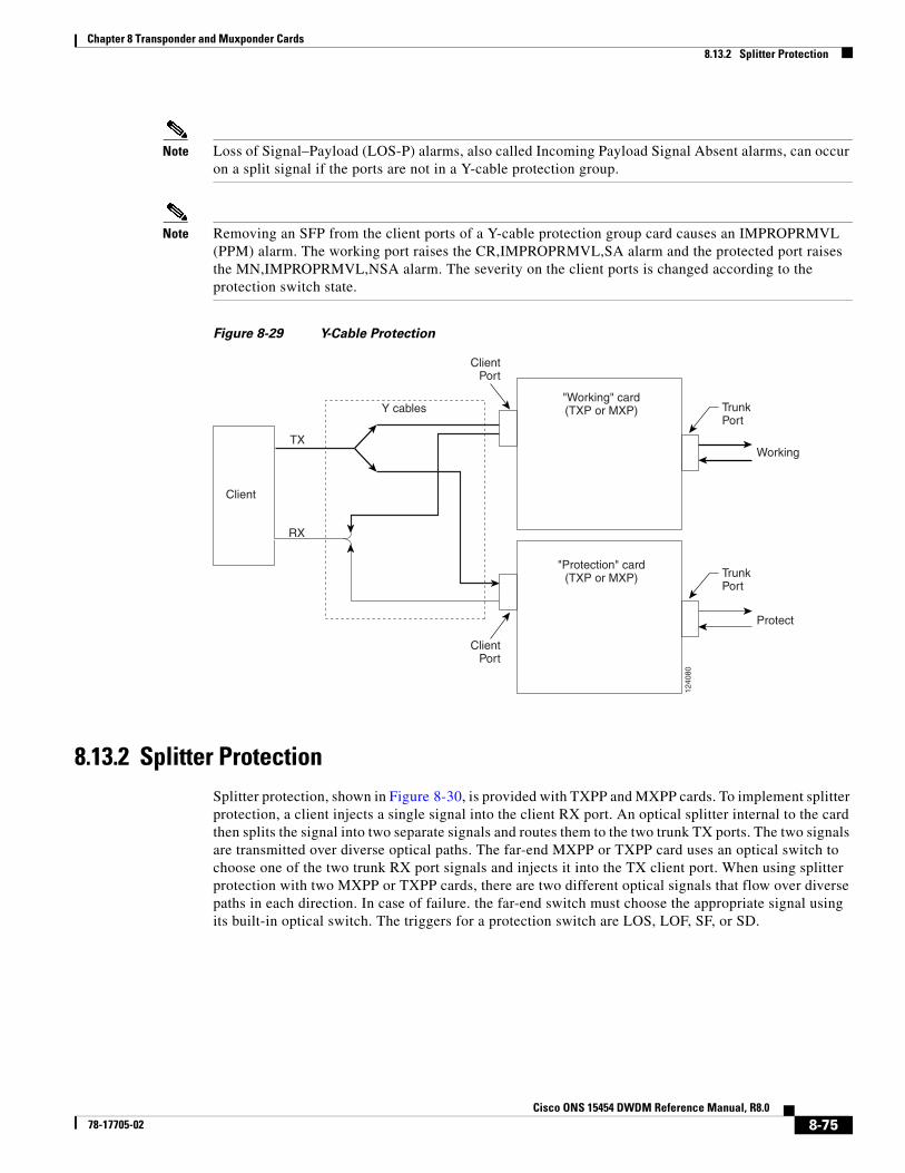
Chapter 8 Transponder and Muxponder Cards8.13.2 Splitter Protection
Note Loss of Signal–Payload (LOS-P) alarms, also called Incoming Payload Signal Absent alarms, can occur on a split signal if the ports are not in a Y-cable protection group.
Note Removing an SFP from the client ports of a Y-cable protection group card causes an IMPROPRMVL (PPM) alarm. The working port raises the CR,IMPROPRMVL,SA alarm and the protected port raises the MN,IMPROPRMVL,NSA alarm. The severity on the client ports is changed according to the protection switch state.
Figure 8-29 Y-Cable Protection
8.13.2 Splitter ProtectionSplitter protection, shown in Figure 8-30, is provided with TXPP and MXPP cards. To implement splitter protection, a client injects a single signal into the client RX port. An optical splitter internal to the card then splits the signal into two separate signals and routes them to the two trunk TX ports. The two signals are transmitted over diverse optical paths. The far-end MXPP or TXPP card uses an optical switch to choose one of the two trunk RX port signals and injects it into the TX client port. When using splitter protection with two MXPP or TXPP cards, there are two different optical signals that flow over diverse paths in each direction. In case of failure. the far-end switch must choose the appropriate signal using its built-in optical switch. The triggers for a protection switch are LOS, LOF, SF, or SD.
Client
"Working" card(TXP or MXP)
"Protection" card(TXP or MXP)
Y cables
TX
RX
Working
Protect
ClientPort
TrunkPort
ClientPort
TrunkPort
1240
80
8-75Cisco ONS 15454 DWDM Reference Manual, R8.0
78-17705-02
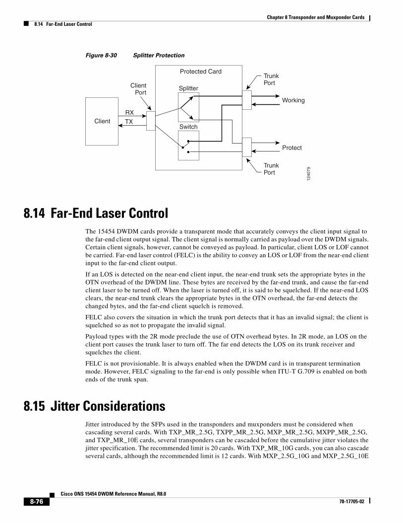
Chapter 8 Transponder and Muxponder Cards8.14 Far-End Laser Control
Figure 8-30 Splitter Protection
8.14 Far-End Laser ControlThe 15454 DWDM cards provide a transparent mode that accurately conveys the client input signal to the far-end client output signal. The client signal is normally carried as payload over the DWDM signals. Certain client signals, however, cannot be conveyed as payload. In particular, client LOS or LOF cannot be carried. Far-end laser control (FELC) is the ability to convey an LOS or LOF from the near-end client input to the far-end client output.
If an LOS is detected on the near-end client input, the near-end trunk sets the appropriate bytes in the OTN overhead of the DWDM line. These bytes are received by the far-end trunk, and cause the far-end client laser to be turned off. When the laser is turned off, it is said to be squelched. If the near-end LOS clears, the near-end trunk clears the appropriate bytes in the OTN overhead, the far-end detects the changed bytes, and the far-end client squelch is removed.
FELC also covers the situation in which the trunk port detects that it has an invalid signal; the client is squelched so as not to propagate the invalid signal.
Payload types with the 2R mode preclude the use of OTN overhead bytes. In 2R mode, an LOS on the client port causes the trunk laser to turn off. The far end detects the LOS on its trunk receiver and squelches the client.
FELC is not provisionable. It is always enabled when the DWDM card is in transparent termination mode. However, FELC signaling to the far-end is only possible when ITU-T G.709 is enabled on both ends of the trunk span.
8.15 Jitter ConsiderationsJitter introduced by the SFPs used in the transponders and muxponders must be considered when cascading several cards. With TXP_MR_2.5G, TXPP_MR_2.5G, MXP_MR_2.5G, MXPP_MR_2.5G, and TXP_MR_10E cards, several transponders can be cascaded before the cumulative jitter violates the jitter specification. The recommended limit is 20 cards. With TXP_MR_10G cards, you can also cascade several cards, although the recommended limit is 12 cards. With MXP_2.5G_10G and MXP_2.5G_10E
Client
Protected Card
Working
Protect
ClientPort
RXTX
Splitter
Switch
TrunkPort
TrunkPort
1240
79
8-76Cisco ONS 15454 DWDM Reference Manual, R8.0
78-17705-02
Chapter 8 Transponder and Muxponder Cards8.16 Termination Modes
cards, any number of cards can be cascaded as long as the maximum reach between any two is not exceeded. This is because any time the signal is demultiplexed, the jitter is eliminated as a limiting factor.
The maximum reach between one transponder and the other must be halved if a Y cable is used. For more information on Y-cable operation, see the “8.13.1 Y-Cable Protection” section on page 8-74.
8.16 Termination ModesTransponder and muxponder cards have various SONET and SDH termination modes that can be configured using CTC (see the “Provision Transponder and Muxponder Cards” chapter in the Cisco ONS 15454 DWDM Procedure Guide). The termination modes are summarized in Table 8-39.
For TXP and MXP cards, adhere to the following conditions while DCC termination provisioning:
• For SDCC/RS-DCC provisioning, the card should be in the Section/RS-DCC or Line/MS-DCC termination mode.
• For LDCC/MS-DCC provisioning, the card should be in the Line/MS-DCC termination mode.
Table 8-39 Termination Modes
Cards Termination Mode Description
All TXP and MXP cards, with the exception of the MXP_2.5G_10G card (see next section of this table)
Transparent Termination All the bytes of the payload pass transparently through the cards.
Section Termination The SONET transport overhead (TOH) section bytes and the SDH regenerator section overhead (SOH) bytes are terminated. None of these SOH bytes are passed through. They are all regenerated, including the SONET TOH section DCC (SDCC) bytes and the SDH regenerator section DCC (RS-DCC) bytes. In the section termination mode, the SONET TOH line and SDH multiplex section overhead bytes are passed transparently.
Line Termination In line termination mode, the section and line overhead bytes for SONET and the overhead bytes for the SDH multiplex and regenerator sections are terminated. None of the overhead bytes are passed through. They are all regenerated, including the SONET SDCC and line DCC (LDCC) bytes and the SDH RS-DCC and multiplexer section DCC (MS-DCC) bytes.
MXP_2.5G_10G1
1. Clients operating at the OC48/STM16 rate are multiplexed into an OC192/STM64 frame before going to OTN or DWDM.
Transparent Termination All of the client bytes of the clients passes transparently through except the following: B1 is rebuilt, S1 is rewritten, A1 to A2 are regenerated, and H1 to H3 are regenerated.
Section Termination The SONET TOH section bytes and the SDH regenerator section overhead bytes are terminated. None of these section overhead bytes are passed through. They are all regenerated, including the SONET TOH section DCC bytes and the SDH RS-DCC bytes. In the section termination mode, the SONET TOH line and SDH multiplex section overhead bytes are passed transparently.
Line Termination In the line termination mode, the section and line overhead bytes for SONET and the overhead bytes for the SDH multiplex and regenerators sections are terminated. None of the overhead bytes are passed through. They are all regenerated, including the SONET SDCC and LDCC bytes and the SDH RS-DCC and MS-DCC bytes.
8-77Cisco ONS 15454 DWDM Reference Manual, R8.0
78-17705-02
Chapter 8 Transponder and Muxponder Cards8.17 SFP and XFP Modules
For more information on enabling termination modes, see the procedures for changing card setting in the “Provision Transponder and Muxponder Cards” chapter of the Cisco ONS 15454 DWDM Procedure Guide.
8.17 SFP and XFP ModulesSFPs and 10-Gbps SFPs (XFPs) are integrated fiber optic transceivers that provide high-speed serial links from a port or slot to the network. For more information on SFPs/XFPs and for a list of SFPs/XFPs supported by the transponder and muxponder cards, see the Installing the GBIC, SFP, SFP+, XFP, CXP, and CFP Optical Modules in Cisco ONS Platforms.
In CTC, SFPs/XFPs are called pluggable port modules (PPMs). To provision SFPs/XFPs and change the line rate for multirate PPMs, see the Cisco ONS 15454 DWDM Procedure Guide.
8-78Cisco ONS 15454 DWDM Reference Manual, R8.0
78-17705-02