Transonic static aeroelastic simulations … List of Figures Figure 1 A schematic diagram of the...
31
Nationaal Nationaal Nationaal Nationaal Lucht- en Lucht- en Lucht- en Lucht- en Ruimtevaartlaboratorium Ruimtevaartlaboratorium Ruimtevaartlaboratorium Ruimtevaartlaboratorium National Aerospace Laboratory NLR NLR-TP-2003-187 Transonic static aeroelastic simulations of Transonic static aeroelastic simulations of Transonic static aeroelastic simulations of Transonic static aeroelastic simulations of fighter aircraft fighter aircraft fighter aircraft fighter aircraft B.B. Prananta and J.J. Meijer This report is based on a presentation held at the 23rd Congress of the International Council on Aeronautical Sciences, Toronto, Canada, 23 September 2002. The work presented in this report is partly funded by the Netherlands Ministry of Defence through the AESIM-MIL project and by the Royal Netherlands Air Force through the F-16 OUTER WING project. This report may be cited on condition that full credit is given to NLR and the authors. Customer: National Aerospace Laboratory NLR Working Plan number: A.1.B.2 Owner: National Aerospace Laboratory NLR Division: Fluid Dynamics Distribution: Unlimited Classification title: Unclassified May 2003 Approved by author: Approved by project manager: Approved by project managing department: Approved by author: Approved by project manager: Approved by project managing department:
Transcript of Transonic static aeroelastic simulations … List of Figures Figure 1 A schematic diagram of the...
Nationaal Nationaal Nationaal Nationaal Lucht- en Lucht- en Lucht- en Lucht- en RuimtevaartlaboratoriumRuimtevaartlaboratoriumRuimtevaartlaboratoriumRuimtevaartlaboratoriumNational Aerospace Laboratory NLR
NLR-TP-2003-187
Transonic static aeroelastic simulations ofTransonic static aeroelastic simulations ofTransonic static aeroelastic simulations ofTransonic static aeroelastic simulations offighter aircraftfighter aircraftfighter aircraftfighter aircraft
B.B. Prananta and J.J. Meijer
This report is based on a presentation held at the 23rd Congress of the InternationalCouncil on Aeronautical Sciences, Toronto, Canada, 23 September 2002.
The work presented in this report is partly funded by the Netherlands Ministry ofDefence through the AESIM-MIL project and by the Royal Netherlands Air Forcethrough the F-16 OUTER WING project.
This report may be cited on condition that full credit is given to NLR and the authors.
Customer: National Aerospace Laboratory NLRWorking Plan number: A.1.B.2Owner: National Aerospace Laboratory NLRDivision: Fluid DynamicsDistribution: UnlimitedClassification title: Unclassified
May 2003
Approved by author: Approved by project manager: Approved by project managingdepartment:
Approved by author: Approved by project manager: Approved by project managingdepartment:

- 3 -NLR-TP-2003-187
Summary
This paper presents static deformation simulations of fighter-type aircraft in transonic flow at var-
ious load factors using the linear approach of MSC.NASTRAN and an NLR in-house developed
Computational Aeroelastic Simulation (CAS) system employing the Euler/Navier-Stokes equa-
tions. The NLR CAS system solves the aeroelastic governing equations in a loosely-coupled
manner. The aerodynamic part is solved using finite-volume method on multiblock structured
grids including an efficient grid deformation technique. Linear structural equations are used with
elasto-mechanical data extracted from NASTRAN. Two configurations are simulated, i.e. with and
without wing-tip missile. The level of bending deformations computed with both NASTRAN and
NLR CAS based on Euler equations are in reasonable agreement. The twist deformations, however,
show differences that may be attributed to the nonlinearities of the transonic flow.
- 4 -NLR-TP-2003-187
Contents
List of Figures 5
List of Symbols 7
1 Introduction 9
2 Analysis method 11
3 Applications 14
4 Concluding remarks 17
5 References 18
18 Figures
(31 pages in total)
- 5 -NLR-TP-2003-187
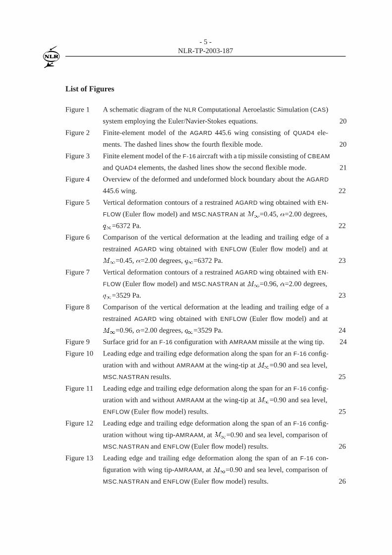
List of Figures
Figure 1 A schematic diagram of the NLR Computational Aeroelastic Simulation (CAS)
system employing the Euler/Navier-Stokes equations. 20
Figure 2 Finite-element model of the AGARD 445.6 wing consisting of QUAD4 ele-
ments. The dashed lines show the fourth flexible mode. 20
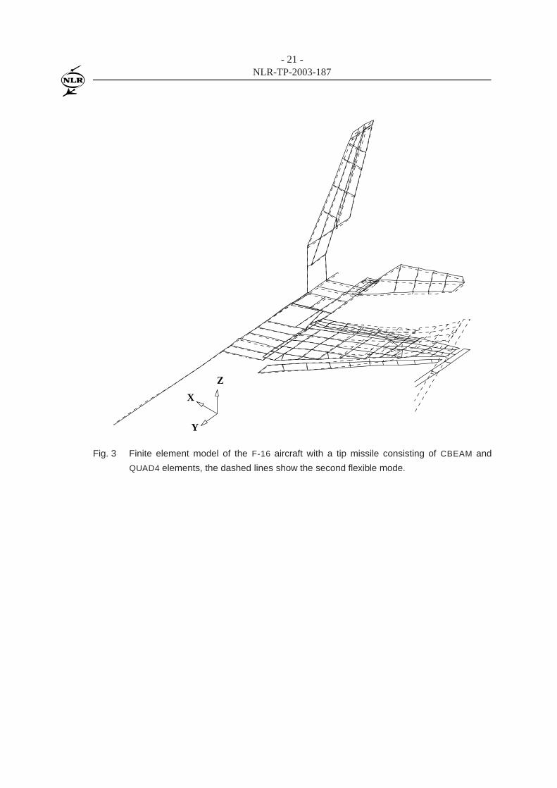
Figure 3 Finite element model of the F-16 aircraft with a tip missile consisting of CBEAM
and QUAD4 elements, the dashed lines show the second flexible mode. 21
Figure 4 Overview of the deformed and undeformed block boundary about the AGARD
445.6 wing. 22
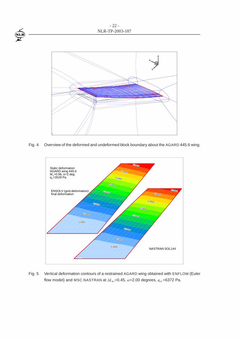
Figure 5 Vertical deformation contours of a restrained AGARD wing obtained with EN-
FLOW (Euler flow model) and MSC.NASTRAN at M1=0.45, �=2.00 degrees,
q1=6372 Pa. 22
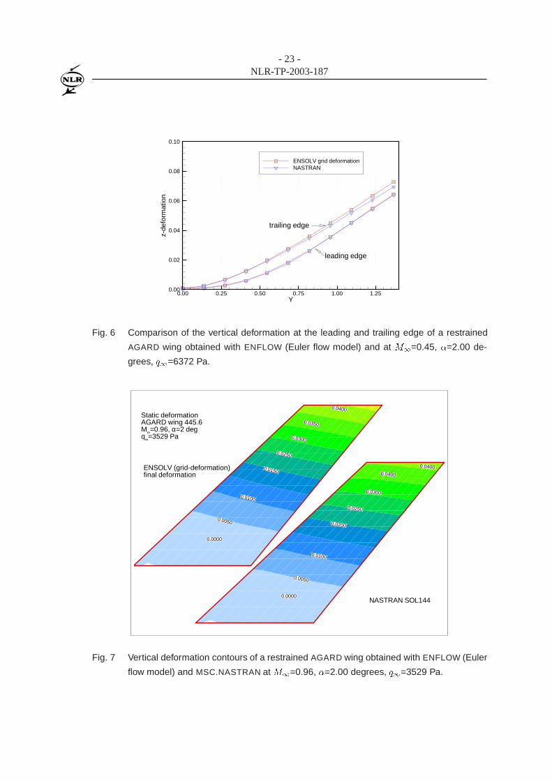
Figure 6 Comparison of the vertical deformation at the leading and trailing edge of a
restrained AGARD wing obtained with ENFLOW (Euler flow model) and at
M1=0.45, �=2.00 degrees, q1=6372 Pa. 23
Figure 7 Vertical deformation contours of a restrained AGARD wing obtained with EN-
FLOW (Euler flow model) and MSC.NASTRAN at M1=0.96, �=2.00 degrees,
q1=3529 Pa. 23
Figure 8 Comparison of the vertical deformation at the leading and trailing edge of a
restrained AGARD wing obtained with ENFLOW (Euler flow model) and at
M1=0.96, �=2.00 degrees, q1=3529 Pa. 24
Figure 9 Surface grid for an F-16 configuration with AMRAAM missile at the wing tip. 24
Figure 10 Leading edge and trailing edge deformation along the span for an F-16 config-
uration with and without AMRAAM at the wing-tip at M1=0.90 and sea level,
MSC.NASTRAN results. 25
Figure 11 Leading edge and trailing edge deformation along the span for an F-16 config-
uration with and without AMRAAM at the wing-tip at M1=0.90 and sea level,
ENFLOW (Euler flow model) results. 25
Figure 12 Leading edge and trailing edge deformation along the span of an F-16 config-
uration without wing tip-AMRAAM, at M1=0.90 and sea level, comparison of
MSC.NASTRAN and ENFLOW (Euler flow model) results. 26
Figure 13 Leading edge and trailing edge deformation along the span of an F-16 con-
figuration with wing tip-AMRAAM, at M1=0.90 and sea level, comparison of
MSC.NASTRAN and ENFLOW (Euler flow model) results. 26
- 6 -NLR-TP-2003-187
Figure 14 Twist angle deformation along the span for an F-16 configuration with and
without AMRAAM at the wing-tip at M1=0.90 and sea level, MSC.NASTRAN
results. 27
Figure 15 Twist angle deformation along the span for an F-16 configuration with and
without AMRAAM at the wing-tip at M1=0.90 and sea level, ENFLOW (Euler
flow model) results. 28
Figure 16 Comparison of pressure distribution between F-16 configuration with AMRAAM
launcher and missile and one with AMRAAM launcher at load factor 1, sea level,
M1=0.90, standard atmosphere. 29
Figure 17 Comparison of pressure distribution between F-16 configuration with AMRAAM
launcher and missile and one with AMRAAM launcher at load factor 5, sea level,
M1=0.90, standard atmosphere. 30
Figure 18 Comparison of pressure distribution between F-16 configuration with AMRAAM
launcher and missile and one with AMRAAM launcher at load factor 9, sea level,
M1=0.90, standard atmosphere. 31

- 7 -NLR-TP-2003-187
List of Symbols
a� free-free flexibility matrix~B body force
C damping matrix~CA force coefficient
f(~x) assumed shape of the deformation for spline purposes, see Eq. 8~Faero aerodynamic force on aerodynamic grids~Fstruc structural force on structural nodes
F(U; ~x; _~x) Euler/Navier-Stokes equations flux matrix
�(r) radial basis function for spline purposes, see Eq. 8
G fluid/structure interpolation matrix~haero surface deformation in aerodynamic model~hstruc surface deformation in structural model
K stiffness matrix
~m surface normal
M mass matrix
M1 freestream Mach number
� mass ratio, see Eq. 5
P(~x) low order polynomial for spline purposes, see Eq. 8
q1 freestream dynamic pressure
R rigid body modifying matrix, see Eq. 9
S(U; ~x; _~x) source term
U flow variables
~u flow velocity�U reduced velocity, see Eq. 5
V � speed index, see Eq. 5
~x displacement_~x velocity

- 8 -NLR-TP-2003-187
This page is intentionally left blank.
- 9 -NLR-TP-2003-187
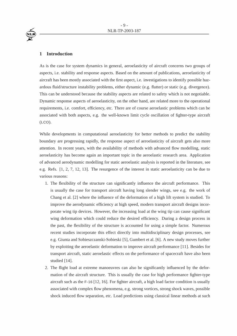
1 Introduction
As is the case for system dynamics in general, aeroelasticity of aircraft concerns two groups of
aspects, i.e. stability and response aspects. Based on the amount of publications, aeroelasticity of
aircraft has been mostly associated with the first aspect, i.e. investigations to identify possible haz-
ardous fluid/structure instability problems, either dynamic (e.g. flutter) or static (e.g. divergence).
This can be understood because the stability aspects are related to safety which is not negotiable.
Dynamic response aspects of aeroelasticity, on the other hand, are related more to the operational
requirements, i.e. comfort, efficiency, etc. There are of course aeroelastic problems which can be
associated with both aspects, e.g. the well-known limit cycle oscillation of fighter-type aircraft
(LCO).
While developments in computational aeroelasticity for better methods to predict the stability
boundary are progressing rapidly, the response aspect of aeroelasticity of aircraft gets also more
attention. In recent years, with the availability of methods with advanced flow modelling, static
aeroelasticity has become again an important topic in the aeroelastic research area. Application
of advanced aerodynamic modelling for static aeroelastic analysis is reported in the literature, see
e.g. Refs. [1, 2, 7, 12, 13]. The resurgence of the interest in static aeroelasticity can be due to
various reasons:
1. The flexibility of the structure can significantly influence the aircraft performance. This
is usually the case for transport aircraft having long slender wings, see e.g. the work of
Chang et al. [2] where the influence of the deformation of a high lift system is studied. To
improve the aerodynamic efficiency at high speed, modern transport aircraft designs incor-
porate wing tip devices. However, the increasing load at the wing tip can cause significant
wing deformation which could reduce the desired efficiency. During a design process in
the past, the flexibility of the structure is accounted for using a simple factor. Numerous
recent studies incorporate this effect directly into multidisciplinary design processes, see
e.g. Giunta and Sobieszczanski-Sobieski [5], Gumbert et al. [6]. A new study moves further
by exploiting the aeroelastic deformation to improve aircraft performance [11]. Besides for
transport aircraft, static aeroelastic effects on the performance of spacecraft have also been
studied [14].
2. The flight load at extreme manoeuvres can also be significantly influenced by the defor-
mation of the aircraft structure. This is usually the case for high performance fighter-type
aircraft such as the F-16 [12, 16]. For fighter aircraft, a high load factor condition is usually
associated with complex flow phenomena, e.g. strong vortices, strong shock waves, possible
shock induced flow separation, etc. Load predictions using classical linear methods at such

- 10 -NLR-TP-2003-187
conditions would increase uncertainties in the results.
3. Wind tunnel measurements in high Reynolds number wind-tunnel facilities such as the Eu-
ropean Transonic Wind tunnel ETW and NASA National Transonic Facility NTF reveal sig-
nificant static aeroelastic deformation effect of the model. Static deformation of a wind
tunnel model requires careful attention especially during studies to determine Reynolds
number effect. Varying tunnel Reynolds number for a fixed Mach number could imply
also variation of dynamic pressure with the associated variation in the static deformation
of the model. Various investigations have therefore been directed towards this problem to
predict accurately the model deformation during the experiment, see e.g. Refs. [1, 7, 13].
The aforementioned static aeroelastic problems are usually associated with transonic flow. There-
fore advanced flow modelling based on the Euler and Navier-Stokes equations is applied in these
studies. However, application of high fidelity flow modelling requires significantly more effort
than the traditional lifting surface methods. This is due to the more realistic geometry modelling,
complex solution procedures, etc. Smart judgement based on the benefit of using advanced flow
modelling is needed to justify the additional effort.
The present paper concerns the second point of the aforementioned issues of static aeroelastic-
ity, load at extreme manoeuvre. Static deformation analyses using advanced flow modelling are
carried out for an F-16 aircraft for a simple loading condition with and without wing tip missile.
The end goal of the exercise is to investigate the effect of carrying a heavy missile at the wing tip
with respect to the stresses occurring in the wing. In the present work, some preliminary studies
are carried out in which the results of the simulation are compared with results obtained with the
linear method available in MSC.NASTRAN. Prior to presenting the results for the F-16 aircraft a
short summary of the method employed in the present study is given along with results for simple
isolated wing of the AGARD standard aeroelastic configuration.
- 11 -NLR-TP-2003-187
2 Analysis method
In the present work, the NLR aeroelastic system is employed. The NLR aeroelastic system is a
collection of tools suitable for a wide range of aeroelastic investigations. Various flow models are
available ranging from lifting surface theory, full-potential, Euler and Navier-Stokes equations.
The tool employing the lifting surface theory and non-linear full-potential equation is integrated
into a system called the AESIM-BASIC. The AESIM-BASIC system is designed for interactive work
and has been used extensively for various aeroelastic investigations such as static aeroelasticity,
transonic flutter, etc., see Refs. [8, 10]. The AESIM-BASIC aeroelastic system is considered mature
and ready of industrial applications.
The aeroelastic simulation method employing the Euler and Navier-Stokes equations, has been
developed for military aircraft applications. The schematic diagram of the system is given in figure
1. The method has been validated for static and dynamic aeroelastic applications and recently has
been successfully applied to model limit cycle oscillation of F-16 aircraft due to shock-induced
flow separation. First results for static aeroelastic applications are presented in Ref. [16]. The
present study has employed this computational aeroelastic simulation method and therefore will
be presented in more detail.
The governing equations for an aeroelastic system consist of the equations governing the dy-
namics of the structure and the equations governing the flow about the structure. Assuming the
deformation of the structure is relatively small, a linearised structural model may be employed.
The non-linear Euler/Navier-Stokes equations are used to model the flow around the structure. In
a nondimensional form the governing equations may be recast as:
M �~x+ C _~x+K~x =1
2V � 2 ~CA(U; ~x; _~x; t) + ~B; (1)
@U
@t+ ~r � F(U; ~x; _~x) = S(U; ~x; _~x): (2)
These equations are coupled through the kinematic condition on the fluid/structure interface. Let
~m be a vector normal to the fluid/structure interface, the condition on the solid surface becomes:
(~u� _~x) � ~m(~x) = 0 for inviscid flow (3)
~u� _~x = 0 for viscous flow; (4)
along with conditions for the other thermodynamic quantities, e.g. adiabatic wall. In equations (1)
to (4) M is the mass matrix, C is the damping matrix, K is the stiffness matrix, ~B is the vector
- 12 -NLR-TP-2003-187
of body force and ~CA is the vector of aerodynamic force coefficients which are function of the
conservative flow variable U governed by the Euler/Navier-Stokes equations. F and S are the flux
matrix and the source term of the Euler/Navier-Stokes equations. For static deformation problems,
the first two terms of equation (1) are dropped.
In addition to the usual similarity parameters involved in aerodynamic analyses, e.g. Reynolds
number Re1 and Mach number M1, fluid/structure interaction parameters are also involved, i.e.
speed index V � and mass ratio �. V � is defined in Ref. [4] as
V � = �U=p�; (5)
with reduced velocity �U = u1=(!refLref) and mass ratio � = mref=(�1vref). All these similarity
parameters are invariant across the fluid/structure boundary and therefore are used as synchroni-
sation parameters.
The set of aeroelastic equations (1) and (2) are solved in a loosely-coupled manner [15], i.e. (1)
using relatively distinct solution procedures for the aerodynamic and structural parts and (2) ap-
plying space and time synchronisation between the parts. The aerodynamic governing equations
are solved using a finite-volume technique on structured multiblock grids. For time-accurate sim-
ulations, an implicit second-order backward difference is employed using a full approximation
storage (FAS) multi-grid Runge-Kutta method for the relaxation. The structural part can be solved
directly in physical coordinates or using a parameterisation in modal space. A transition matrix
method [3, 15] is employed to integrate the structural equations in time.
Fluid/structure iteration is carried out for each time step leading to a converged solution for the
whole aeroelastic system. To reach the final deformation quickly, in case of a static deformation
simulation, a large artificial damping is introduced into the system. Otherwise a simple iteration
scheme can also be applied using only the time-independent terms of equation (1).
Trim analysis can also be conducted in which the angle of attack and control surface deflections are
changed in an iterative manner to obtain a desired set of target forces, e.g. lift force corresponding
to the aircraft weight and load factor, zero moments, etc. In the present implementation, the trim
analysis is solved separately at each fluid/structure iteration assuming a weak coupling between
the structural deformation and the trim equations, see Ref. [16] for a more detailed description.
So far, satisfactory convergence has been obtained using this strategy.
During the fluid structure iteration the structural part provides the surface deformation to the aero-
dynamic part and the aerodynamic part gives the aerodynamic load to the structural part. Since

- 13 -NLR-TP-2003-187
in most cases the modelling of fluid/structure interface according to the aerodynamic and struc-
tural requirements is different, an interpolation method is required. The displacement vector in
the aerodynamic grid,~haero , can be expressed in terms of the displacement vector in the structural
grid points, ~hstruc, as
~haero = G~hstruc (6)
where G is the interpolation or spline matrix between the two surface grid systems. Requiring that
the data exchange between the two domains conserves the virtual work, the point loads vector at
structural grid, ~Fstruc, has to be computed from that at the aerodynamic grid as:
~Fstruc = GT ~Faero: (7)
where ~Faero is the point loads vector at the aerodynamic grids. The spline matrix G is defined
using global spline technique for which a function f(~x) is assumed to have the form of:
f(~x) � P(~x) + �(r); (8)
with P is a low order polynomial and � is a radial function. Surface spline or volume spline
methods are used in the present exercises. A detailed discussion on the numerical computation of
G matrix can be found in Ref. [9].
The grid deformation method for structured multiblock grids is a combination of a volume spline
technique and a transfinite interpolation (TFI) method. A multi-block grid consists of a set of
three-dimensional blocks fBg bounded by six two-dimensional faces fFg. Each of the faces fFg
are bounded by four one-dimensional edges fEg. At the ends of an edge two vertices fVg are
defined.
The grid deformation method takes the deformations of the vertices which lie on the fluid/structure
interface as the input. During the first step, these deformations are interpolated into the edges in
the field using the three-dimensional volume spline method [9]. Subsequently, the deformations
on the faces are computed using TFI based on the input of deformation of their bounding edges,
which are either deformed by the volume spline during the first step or given as input in case they
lie on the fluid/structure interface. Finally, the face deformations, again which are either results
from the second step or input from the fluid/structure interface, are interpolated into the block
interior using also a TFI technique, see Ref. [18] for a more detailed description.

- 14 -NLR-TP-2003-187
3 Applications
Applications are presented for the AGARD 445.6 wing mounted on wind tunnel wall and free-
flying F-16 aircraft in a simple air-to-air configuration. The structural data, i.e. flexibility and
mass matrices, are obtained using MSC.NASTRAN. To obtain the desired data, the MSC.NASTRAN
is executed for normal mode analysis where at certain stages of the computation the mass and
stiffness matrices are written as extra outputs. The stiffness matrix is subsequently inverted and
used as input of the ENFLOW system. The commands to produce extra outputs are implemented
using DMAP.
The structural properties of the AGARD 445.6 wing are represented by equivalent shell and plate
elements (the CQUAD4 shell element with 24 DOF’s). Figure 2 shows the finite elements model
of the AGARD 445.6 wing. The resulting stiffness matrix can be directly inverted to obtain the
flexibility matrix.
Structural properties of F-16 configuration are represented by a combination of shell/plate ele-
ments (CQUAD4) with beam (CBEAM) and bar (CBAR) elements, see figure 3. A symmetrical
free-flight configuration is modelled by putting constraints along the fuselage and defining the
rigid body degrees of freedom (using SUPORT command) of normal translation and pitching ro-
tation. After a normal mode analysis using MSC.NASTRAN the so-called free-free mode shapes
are obtained along with free-free stiffness and mass matrices as extra outputs. Note that a free-
free stiffness matrix can not be inverted directly. First, the DOF’s at the point where the rigid
body modes are defined (SUPORT point), are removed to obtain a restrained stiffness matrix. The
restrained stiffness matrix can then be inverted straightforwardly to obtain restrained flexibility
matrix. Subsequently, the necessary modification, based on the DOF’s at the SUPORT point, is
applied to the restrained flexibility matrix to obtain a free-free flexibility matrix a� , see Ref. [17]
for a more detailed description:
a� = RK�1
restrainedRT ; (9)
where Krestrained is the restrained part of the stiffness matrix K and R is the rigid body modifying
matrix.
For the AGARD 445.6 wing, the structural data of the weakened model No. 3 is selected. The
following conditions are considered: (1) a subsonic condition with M1 = 0:45 and q1 = 6372
Pa and (2) a transonic condition with M1 = 0:96 and q1 = 2935 Pa, both at an angle of attack
� = 2 degrees. These flow conditions have been taken from Ref. [19] and represent the flutter
boundary at zero angle of attack.
- 15 -NLR-TP-2003-187
The results of ENFLOW for the AGARD 445.6 wing at the subsonic condition and those of NAS-
TRAN are presented in figures 5 and 6. The total load acting on the wing consists of the aerody-
namic load and the inertial load due to gravity (i.e. 1g load). The results of ENFLOW have been
obtained after 20 fluid/structure iterations with an under-relaxation coefficient 0.5. The vertical
deformations in these figures are normalised using the root chord length. A maximum deforma-
tion of 6.5% of the chord at the wing tip is observed. ENFLOW (Euler flow model) and NASTRAN
results show good agreement for the subsonic condition. For the transonic condition, differences
are expected, although these should not be very large because the wing has a sweep angle of 45
degrees and a relatively thin cross section, combined with relatively low angle of attack. Figure
7 shows the contour of vertical deformation and figure 8 shows the deformations of leading edge
and trailing edge along the span wise direction.
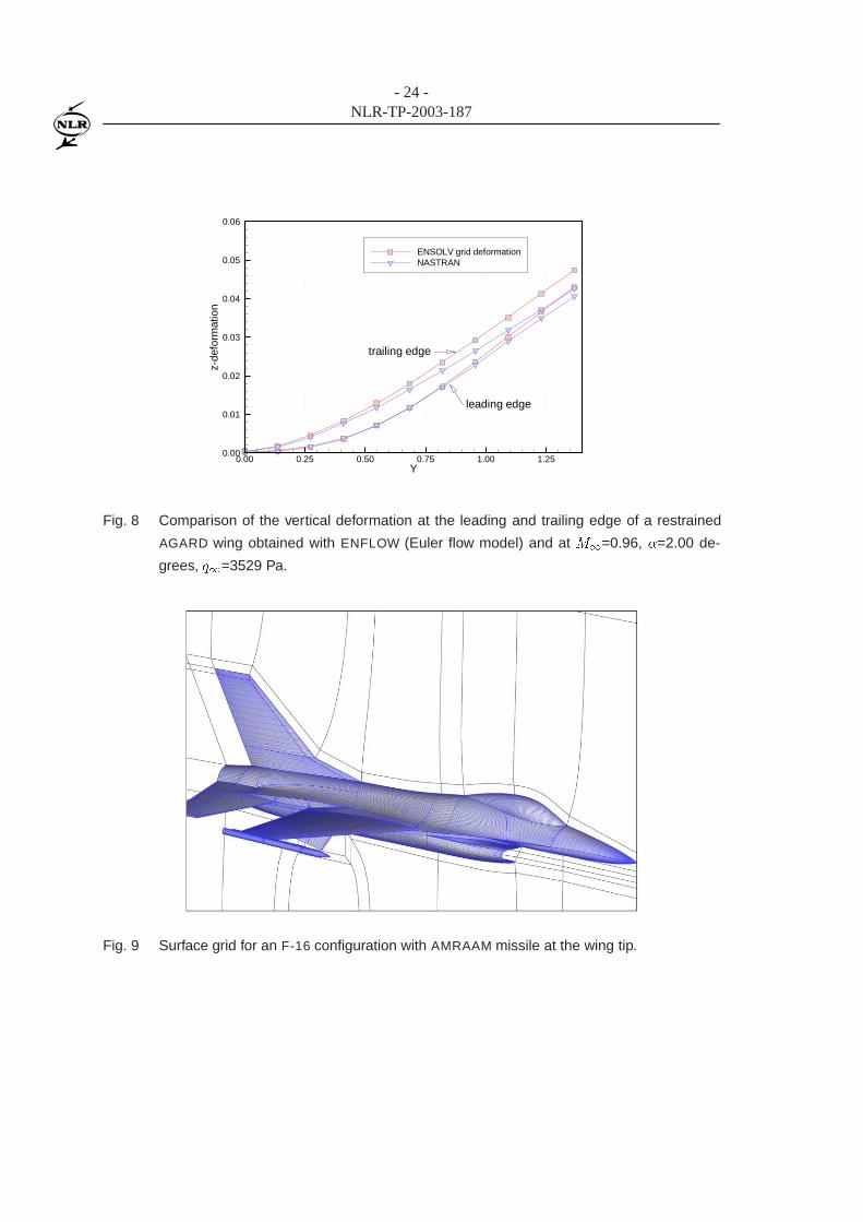
The next applications concern the F-16 aircraft in air-to-air configuration. Simulations are carried
out for the configuration with and without AMRAAM missile at the wing tip with full wing fuel
tanks. A symmetrical pull-up manoeuvre is considered forM1=0.90 at sea level for three different
load factors: viz. 1, 5 and 9. In the present work Euler flow modelling is used.
During the simulations, trimming is conducted only for the angle of attack to obtain the correct lift
which balances the inertial force for the specified load factor. This first approximation is justified
by the results of NASTRAN which shows relatively small deflection of horizontal stabiliser when
included as a trim parameter. Current work also includes an all-moving horizontal stabiliser and
flaperon to balance the pitching moment.
The grids for the simulation consist of about 2 millions cells with three multigrid levels. One of
the surface grids for the configuration with wing tip missile is shown in figure 9. These grids have
been used also in the work presented in Ref. [16] where the grids were found fine enough after
a grid density study. Each complete static aeroelastic simulation requires a CPU time of about 2
hours and 3 gigabytes of core memory on the NEC-SX5/8B computer. Most of the computations
have been conducted using 4 processors requiring only about half an hour wall clock time.
The NASTRAN results have been obtained using the static aeroelastic option SOL 144. Angle of
attack and horizontal stabiliser position have been used as the trim variables.
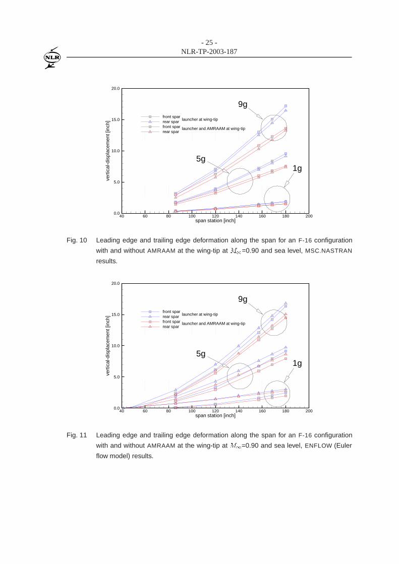
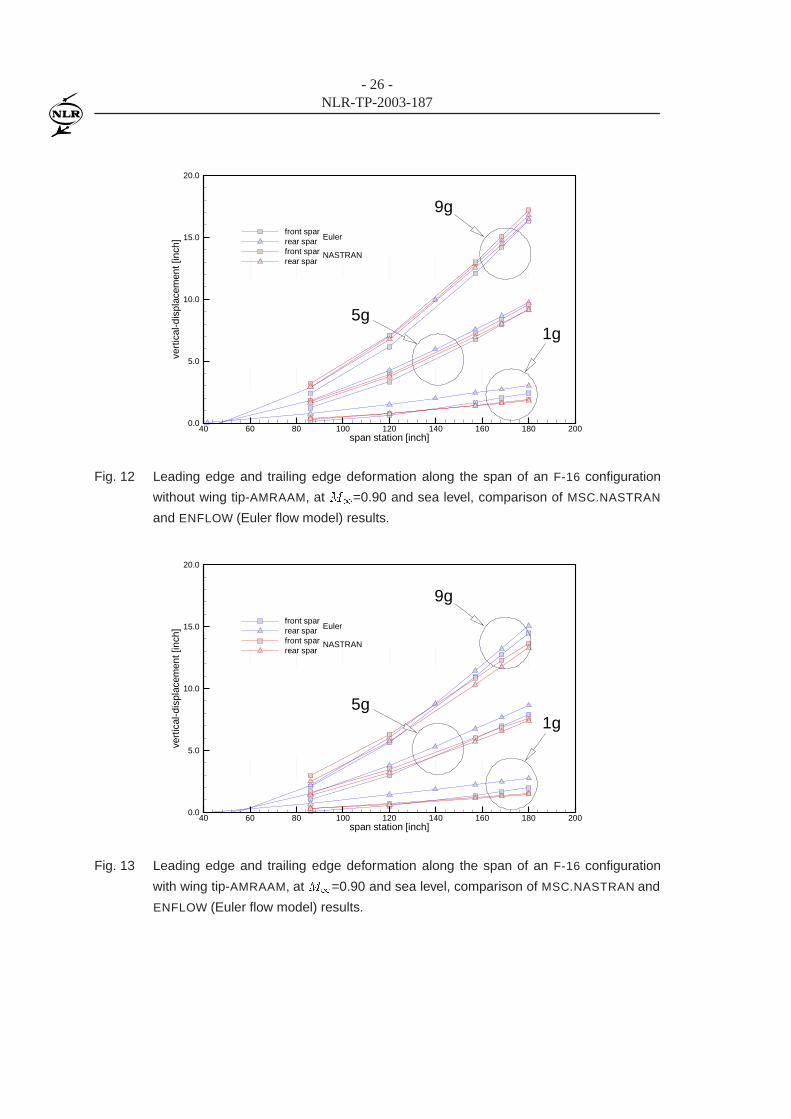
The vertical deformations of the leading and trailing edge along the span of the wing are shown
in figure 10 for NASTRAN results and in figure 11 for ENFLOW results. The results of NASTRAN
clearly show a regular change from low to high load factor due to its linear underlying theory.
Although the configuration with a wing tip missile requires higher lift, a lower deformation level
- 16 -NLR-TP-2003-187
is observed due to the inertia effect of the missile. The differences between missile/no missile
at the wing-tip exhibit also a systematic change from low to high load factor. For the ENFLOW
results the changes from low to high load factor is not as regular as the results of NASTRAN. This
may be due to the nonlinearities of the aerodynamic part of the aeroelastic system. Comparison
of the results between NASTRAN and ENFLOW are depicted in figure 12 for the configuration
without wing tip missile and in figure 13 for the configuration with wing tip missile. In general,
the differences are relatively small. The computed level of deformation at the wing tip has been
also found in the flight test conducted by the Royal Netherlands Air Force (RNLAF). Comparison
with the RNLAF flight test results will be presented in a future paper.
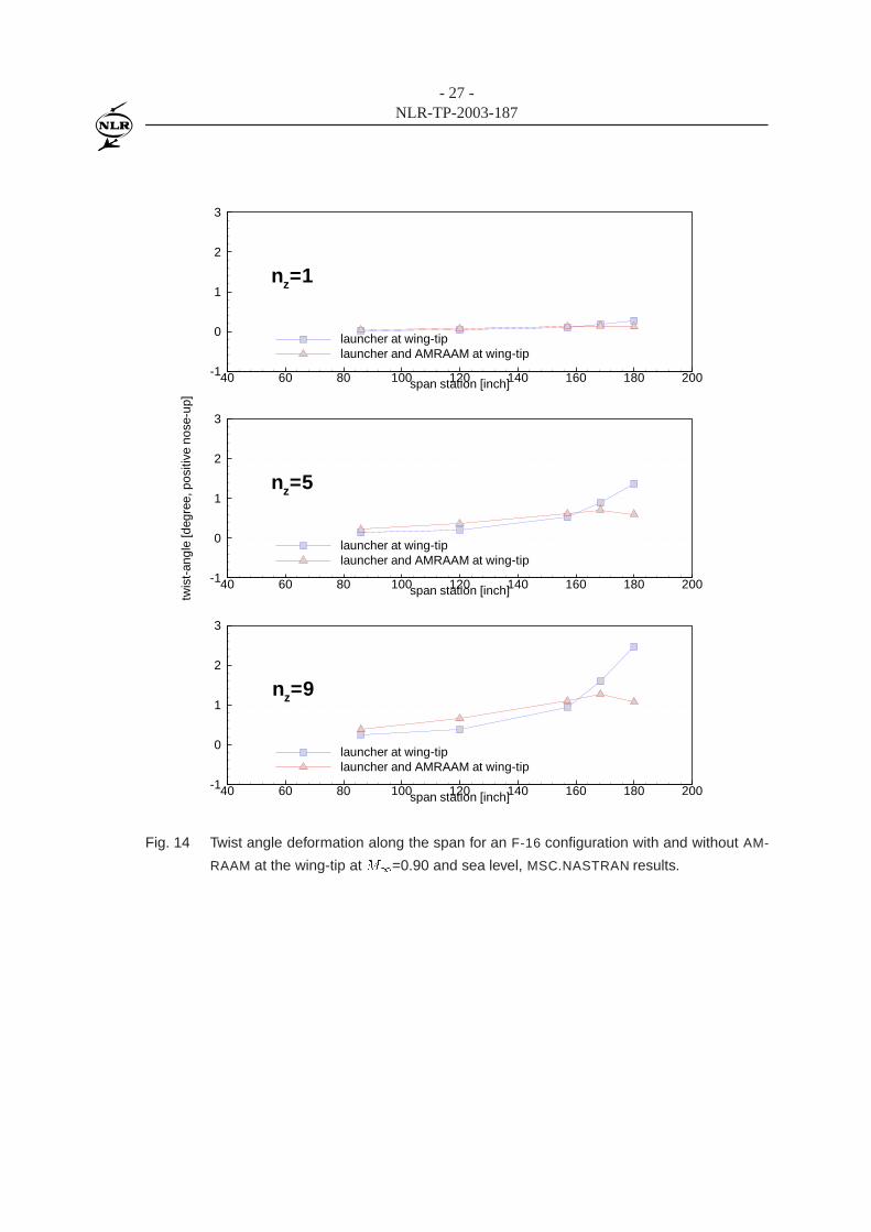
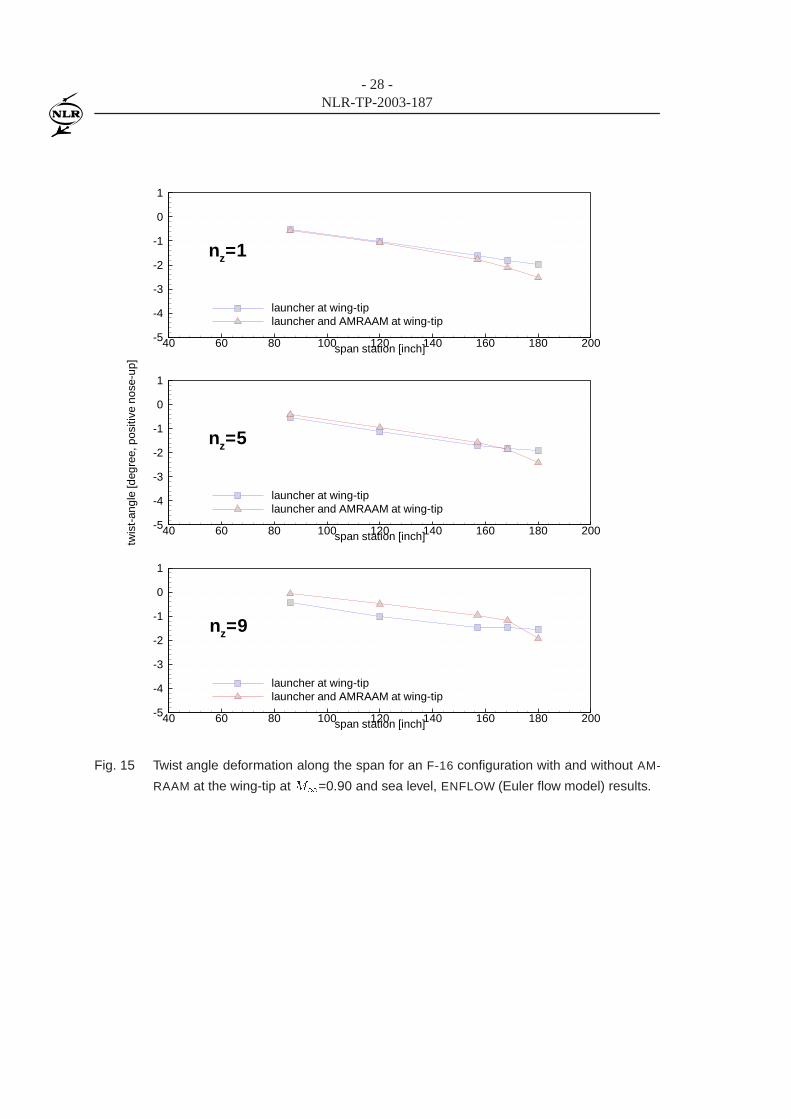
Results concerning the twist angle show a different behaviour between NASTRAN and ENFLOW.
The NASTRAN results exhibit an increasing nose-up twist deformation from the root to the tip of
the wing. The level of the nose-up twist deformation grows with increasing load factor. On the
contrary the ENFLOW results show an increasing nose-down twist deformation from the root to the
tip of the wing. The configuration with tip missiles shows for both NASTRAN results and ENFLOW
results a decreasing (nose-down) twist deformation near the wing tip area, compared to the con-
figuration without tip missiles. The differences in twist deformation are still under investigation.
The different behaviour of the twist angle as opposed to the bending deformation suggests that the
local aerodynamic moments are different between NASTRAN and ENFLOW simulations. As will
be described in the following paragraph, ENFLOW results using Euler flow modelling contains
strong shock waves on the upper side of the wing that influence the local moment distribution.
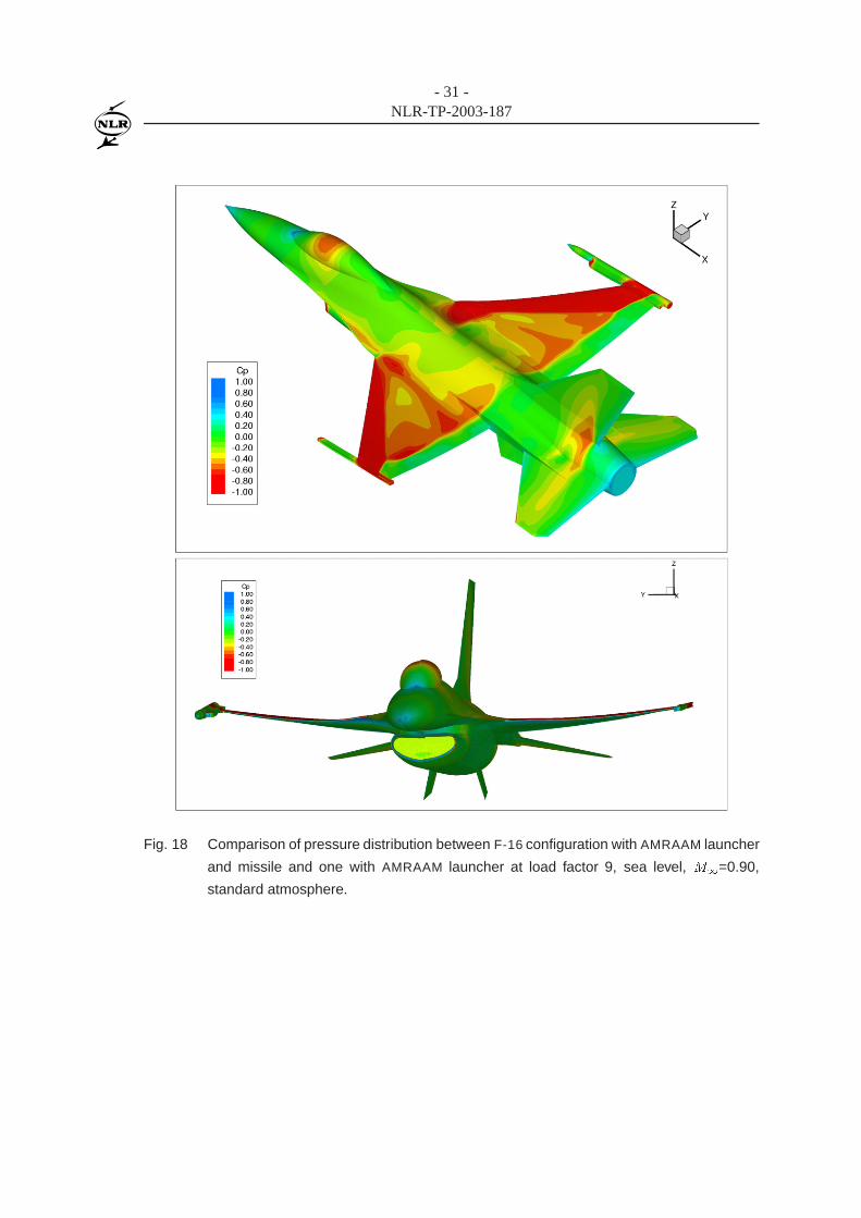
Finally, the surface pressure distributions and impressions of the deformed wing are shown in
figure 16, 17 and 18 for M1=0.90, at sea level for load factors 1, 5 and 9, respectively. At a
load factor 1, only aft shock waves exist on the upper side of the wing. In addition to the aft
shock waves, the forward shock waves also exist for load factors 5 and 9, creating complex flow
structure close to the wing tip. The configuration with a missile at the wing tip in all load cases
shows stronger shock waves. For the load factor of 9 the shock waves are very strong, calling
for improvement on the current flow modelling where viscosity, and thereby the shock-boundary
layer interaction, is neglected. Work is underway to analyse the case using Reynolds-Averaged
Navier-Stokes flow modelling instead of Euler flow modelling.

- 17 -NLR-TP-2003-187
4 Concluding remarks
Static aeroelastic simulations of a fighter-type aircraft at various load factor conditions have been
presented. Two methods have been used, being MSC.NASTRAN and the in-house developed EN-
FLOW aeroelastic system employing a linear structural model and the non-linear Euler/Navier-
Stokes equations. Results are presented for the simple AGARD 445 wing restrained at the wind
tunnel wall in subsonic and transonic flow and for an F-16 aircraft in air-to-air configuration at
transonic flow and various load factors.
Results for the AGARD 445 wing for the subsonic case show good agreement between the linear
method of NASTRAN and the ENFLOW system with non-linear aerodynamic method. Differences
are observed for the transonic case which may be attributed to nonlinearities in the flow.
Results for the F-16 configuration obtained with both NASTRAN and ENFLOW show that the effect
of carrying a missile at the wing tip is to reduce the bending deformation. The reduction of the
bending deformation predicted by ENFLOW in Euler mode is lower than that by the linear method
of NASTRAN.
Results of ENFLOW for all load factors show a nose-down twist deformation which is larger at the
wing tip region when the tip missile is attached. For the case without tip-missile, the nose-down
twist deformation reduces when the load factor increases.
Finally it is noted that for the highest load factor, the shock waves above the wing are very strong,
which led to the current work at NLR which employs Navier-Stokes equations to model the strong
shock wave boundary layer interaction.
- 18 -NLR-TP-2003-187
5 References
1. A.W. Burner, T. Liu, S. Garg, T.A. Ghee, and N.J. Taylor. Aeroelastic deformation measure-
ments of flap, gap, and overhang on a semispan model. Journal of Aircraft, 38(6):1147–1154,
2001.
2. K.C. Chang, H.H. Chen, T. Tzong, and T. Cebeci. Prediction of aeroelastic effects of aircraft
configurations including high lift systems. ICAS Paper 2000.275.1, ICAS, 2000.
3. J.W. Edwards, R.W. Bennett, W. Whitlow Jr., and D.A. Seidel. Time marching transonic
flutter solutions including angle of attack effects. AIAA Paper 82-0685, AIAA, 1982.
4. B.J.G. Eussen, M.H.L. Hounjet, J.J. Meijer, B.B. Prananta, and I W. Tjatra. Perspectives of
NLR methods to predict wing/store flutter and dynamic loads of fighter-type aircraft. ICAS
Paper 2000.461.1, ICAS, also NLR-TP-2000-447, NLR, 2000.
5. A.A. Giunta and J. Sobieszczanski-Sobieski. Progress toward using sensitivity derivatives in
a high-fidelity aeroelastic analysis of a supersonic transport. AIAA Paper 98-4763, AIAA,
1998.
6. C.R. Gumbert, G.J.-W. Hou, and P.A. Newman. Simultaneous Aerodynamic and Structural
Analysis and Design Optimization (SASDO) for a 3-D Wing. AIAA Paper 2001-2527, AIAA,
2001.
7. J.R. Hooker, A.W. Burner, and R. Valla. Static aeroelastic analysis of transonic wind tunnel
models using finite element methods. AIAA Paper 97-2243, AIAA, 1997.
8. M.H.L. Hounjet and B.J.G. Eussen. Outline and application of the NLR aeroelastic simulation
method. In Proceedings of 19th Congress of ICAS, pages 1418–1441, Anaheim, 1994. ICAS,
also NLR-TP-94422, NLR, 1994.
9. M.H.L. Hounjet and J.J. Meijer. Evaluation of Elastomechanical and Aerodynamic Data
Transfer Methods for Non-planar Configurations in Computational Aeroelastic Analysis. In
Proceedings of 1995 CEAS International Forum on Aeroelasticity and Structural Dynamics,
pages 11.1–11.24, Manchester, June 1995. Royal Aeronautical Society, also NLR-TP-95690,
NLR, 1995.
10. M.H.L. Hounjet, B.B. Prananta, and B.J.G. Eussen. Frequency domain unsteady aerodynam-
ics in/from aeroelastic simulation. In Proceedings of 1999 International Forum on Aeroelas-
ticity and Structural Dynamics, Williamsburg, 1999. CEAS/AIAA/ICASE/NASA Langley,
also NLR-TP-99256, NLR, 1999.
11. S.I. Kuzmina, G. Amiryants, J. Schweiger, J. Cooper M. Amprokidis, and O. Sensburg. Re-
view and outlook on active and passive aeroelastic design concepts for future aircraft. ICAS
Paper 2002.432.1, ICAS, 2002.
- 19 -NLR-TP-2003-187
12. M. Love, T. De La Garza, E. Charlton, and D. Eagle. Computational aeroelasticity in high
performance aircraft flight loads. ICAS Paper 2000.481.1, ICAS, 2000.
13. L. R. Owens, Jr. and R. A. Wahls. Reynolds Number Effects on a Supersonic Transport at
Subsonic High-Lift Conditions. AIAA Paper 2001-0911, AIAA, 2001.
14. R.K. Prabhu. Summary Report of the Orbital X-34 Wing Static Aeroelastic models using
finite element methods. NASA CR 2001-210850, NASA, 2001.
15. B.B. Prananta and M.H.L. Hounjet. Large time step aero-structural coupling procedures for
aeroelastic simulation. In Proceedings of 1997 CEAS International Forum on Aeroelasticity
and Structural Dynamics, volume 2, pages 63–71, Rome, June 1997. Associazione Italiana di
Aeronautica ed Astronautica, also NLR-TP-97619, NLR, 1997.
16. B.B. Prananta, I W. Tjatra, S.P. Spekreijse, J.C. Kok, and J.J. Meijer. Static aeroelastic sim-
ulation of military aircraft configuration in transonic flow. In Proceedings of International
Forum on Aeroelasticity and Structural Dynamics, June 4-6 2001. AIAE, also NLR-TP-2001-
346, NLR, 2001.
17. W.P. Rodden and J.R. Love. Equations of motion of a quasisteady flight vehicle utilizing
restrained static aeroelastic characteristics. AIAA Journal, 22(9):802–809, 1979.
18. S.P. Spekreijse, B.B. Prananta, and J.C. Kok. A simple, robust and fast algorithm to compute
deformations of multi-block structured grids. NLR Report TP-2002-105, NLR, 2002.
19. E.C. Yates Jr., N.S. Land, and J.T. Foughner Jr. Measured and calculated subsonic and tran-
sonic flutter characteristics of a 45o sweptback wing planform in air and in Freon-12 in the
Langley Transonic Dynamics Tunnel. Report TN-D-1616, NASA, 1963.

- 20 -NLR-TP-2003-187
Figures
������������� �������������������������
������������ �����������������
DXXX
MASTER Geometrydatabase
CFD Geometrypreprocessor
FEM Modeler
Postprocessor
FEM Analysis
Elasto-mechanicalPreprocessor
Motion Analyzer
Postprocessor
Other System Dynamic Data
User’s Elasto-mechanical
Data
ENFLOW SystemENFLOW System NLR Fluid-Structure InteractionNLR Fluid-Structure Interaction
FM,FCS,Propulsion,etc.
Grid Generator
Domain Modeler
Flow Solver
Online Grid Deformer Aero-structuralInterpolation
OfflineGeometry Deformer
Fig. 1 A schematic diagram of the NLR Computational Aeroelastic Simulation (CAS) system
employing the Euler/Navier-Stokes equations.
Fig. 2 Finite-element model of the AGARD 445.6 wing consisting of QUAD4 elements. The
dashed lines show the fourth flexible mode.
- 21 -NLR-TP-2003-187
Y
X
Z
Fig. 3 Finite element model of the F-16 aircraft with a tip missile consisting of CBEAM and
QUAD4 elements, the dashed lines show the second flexible mode.
- 22 -NLR-TP-2003-187
X
Y
Z
X
Y
Z
Fig. 4 Overview of the deformed and undeformed block boundary about the AGARD 445.6 wing.
0.0050
0.0050
0.0150
0.0250
0.0350
0.0450
0.0550
0.0650Static deformationAGARD wing 445.6M∞=0.96, α=2 degq∞=3529 Pa
ENSOLV (grid-deformation)final deformation
NASTRAN SOL1440.0050
0.0050
0.0200
0.0300
0.0400
0.0500
0.0600
0.0650
Fig. 5 Vertical deformation contours of a restrained AGARD wing obtained with ENFLOW (Euler
flow model) and MSC.NASTRAN at M1=0.45, �=2.00 degrees, q1=6372 Pa.
- 23 -NLR-TP-2003-187
Y
z-de
form
atio
n
0.00 0.25 0.50 0.75 1.00 1.250.00
0.02
0.04
0.06
0.08
0.10
ENSOLV grid deformationNASTRAN
leading edge
trailing edge
Fig. 6 Comparison of the vertical deformation at the leading and trailing edge of a restrained
AGARD wing obtained with ENFLOW (Euler flow model) and at M1=0.45, �=2.00 de-
grees, q1=6372 Pa.
0.0000
0.0050
0.0100
0.0150
0.0250
0.0300
0.0350
0.0400Static deformationAGARD wing 445.6M∞=0.96, α=2 degq∞=3529 Pa
ENSOLV (grid-deformation)final deformation
NASTRAN SOL1440.0000
0.0050
0.0100
0.0200
0.0250
0.0300
0.0400
0.0400
Fig. 7 Vertical deformation contours of a restrained AGARD wing obtained with ENFLOW (Euler
flow model) and MSC.NASTRAN at M1=0.96, �=2.00 degrees, q1=3529 Pa.
- 24 -NLR-TP-2003-187
Y
z-de
form
atio
n
0.00 0.25 0.50 0.75 1.00 1.250.00
0.01
0.02
0.03
0.04
0.05
0.06
ENSOLV grid deformationNASTRAN
leading edge
trailing edge
Fig. 8 Comparison of the vertical deformation at the leading and trailing edge of a restrained
AGARD wing obtained with ENFLOW (Euler flow model) and at M1=0.96, �=2.00 de-
grees, q1=3529 Pa.
Fig. 9 Surface grid for an F-16 configuration with AMRAAM missile at the wing tip.
- 25 -NLR-TP-2003-187
span station [inch]
vert
ical
-dis
plac
emen
t[in
ch]
40 60 80 100 120 140 160 180 2000.0
5.0
10.0
15.0
20.0
front sparrear sparfront sparrear spar
launcher and AMRAAM at wing-tip
launcher at wing-tip
5g
9g
1g
Fig. 10 Leading edge and trailing edge deformation along the span for an F-16 configuration
with and without AMRAAM at the wing-tip at M1=0.90 and sea level, MSC.NASTRAN
results.
span station [inch]
vert
ical
-dis
plac
emen
t[in
ch]
40 60 80 100 120 140 160 180 2000.0
5.0
10.0
15.0
20.0
front sparrear sparfront sparrear spar
launcher and AMRAAM at wing-tip
launcher at wing-tip
5g
9g
1g
Fig. 11 Leading edge and trailing edge deformation along the span for an F-16 configuration
with and without AMRAAM at the wing-tip at M1=0.90 and sea level, ENFLOW (Euler
flow model) results.
- 26 -NLR-TP-2003-187
span station [inch]
vert
ical
-dis
plac
emen
t[in
ch]
40 60 80 100 120 140 160 180 2000.0
5.0
10.0
15.0
20.0
front sparrear sparfront sparrear spar
NASTRAN
Euler
5g
9g
1g
Fig. 12 Leading edge and trailing edge deformation along the span of an F-16 configuration
without wing tip-AMRAAM, at M1=0.90 and sea level, comparison of MSC.NASTRAN
and ENFLOW (Euler flow model) results.
span station [inch]
vert
ical
-dis
plac
emen
t[in
ch]
40 60 80 100 120 140 160 180 2000.0
5.0
10.0
15.0
20.0
front sparrear sparfront sparrear spar
NASTRAN
Euler
5g
9g
1g
Fig. 13 Leading edge and trailing edge deformation along the span of an F-16 configuration
with wing tip-AMRAAM, at M1=0.90 and sea level, comparison of MSC.NASTRAN and
ENFLOW (Euler flow model) results.
- 27 -NLR-TP-2003-187
span station [inch]twis
t-an
gle
[deg
ree,
posi
tive
nose
-up]
40 60 80 100 120 140 160 180 200-1
0
1
2
3
launcher at wing-tiplauncher and AMRAAM at wing-tip
nz=5
span station [inch]40 60 80 100 120 140 160 180 200-1
0
1
2
3
launcher at wing-tiplauncher and AMRAAM at wing-tip
nz=9
span station [inch]40 60 80 100 120 140 160 180 200-1
0
1
2
3
launcher at wing-tiplauncher and AMRAAM at wing-tip
nz=1
Fig. 14 Twist angle deformation along the span for an F-16 configuration with and without AM-
RAAM at the wing-tip at M1=0.90 and sea level, MSC.NASTRAN results.
- 28 -NLR-TP-2003-187
span station [inch]40 60 80 100 120 140 160 180 200-5
-4
-3
-2
-1
0
1
launcher at wing-tiplauncher and AMRAAM at wing-tip
nz=1
span station [inch]twis
t-an
gle
[deg
ree,
posi
tive
nose
-up]
40 60 80 100 120 140 160 180 200-5
-4
-3
-2
-1
0
1
launcher at wing-tiplauncher and AMRAAM at wing-tip
nz=5
span station [inch]40 60 80 100 120 140 160 180 200-5
-4
-3
-2
-1
0
1
launcher at wing-tiplauncher and AMRAAM at wing-tip
nz=9
Fig. 15 Twist angle deformation along the span for an F-16 configuration with and without AM-
RAAM at the wing-tip at M1=0.90 and sea level, ENFLOW (Euler flow model) results.

- 29 -NLR-TP-2003-187
Fig. 16 Comparison of pressure distribution between F-16 configuration with AMRAAM launcher
and missile and one with AMRAAM launcher at load factor 1, sea level, M1=0.90,
standard atmosphere.

- 30 -NLR-TP-2003-187
Fig. 17 Comparison of pressure distribution between F-16 configuration with AMRAAM launcher
and missile and one with AMRAAM launcher at load factor 5, sea level, M1=0.90,
standard atmosphere.
- 31 -NLR-TP-2003-187
Fig. 18 Comparison of pressure distribution between F-16 configuration with AMRAAM launcher
and missile and one with AMRAAM launcher at load factor 9, sea level, M1=0.90,
standard atmosphere.