TRANSMISSION/TRANSAXLE - MazdaSpeed protege … · 2009-12-28 · TRANSMISSION/TRANSAXLE 05 SECTION...
69
05–02–1 05 TRANSMISSION/TRANSAXLE SECTION 05–02 Toc of SCT ON-BOARD DIAGNOSTIC . . . . 05-02 SYMPTOM TROUBLESHOOTING . . . . . . 05-03 CLUTCH . . . . . . . . . . . . . . . . . . 05-10 MANUAL TRANSAXLE [F25M-R] . . . . . . . . . . . . . . . . . 05-15A MANUAL TRANSAXLE [G15M-R]. . . . . . . . . . . . . . . . . 05-15B MANUAL TRANSAXLE SHIFT MECHANISM . . . . . . . 05-16 AUTOMATIC TRANSAXLE . . . 05-17 AUTOMATIC TRANSAXLE SHIFT MECHANISM . . . . . . . 05-18 TECHNICAL DATA . . . . . . . . . 05-50 SERVICE TOOLS. . . . . . . . . . . 05-60 Toc of SCT 05–02 ON-BOARD DIAGNOSTIC AUTOMATIC TRANSAXLE CONTROL SYSTEM WIRING DIAGRAM. . . . . . . . . . . . . . . . . 05–02–2 FOREWARD . . . . . . . . . . . . . . . . . . . . . . . 05–02–6 AUTOMATIC TRANSAXLE ON-BOARD DIAGNOSTIC FUNCTION . . . . . . . . . . . 05–02–6 DTC Reading Procedure . . . . . . . . . . . . 05–02–6 AFTER REPAIR PROCEDURE . . . . . . . . 05–02–6 DTC TABLE . . . . . . . . . . . . . . . . . . . . . . . 05–02–7 DTC P0500 . . . . . . . . . . . . . . . . . . . . . . . . 05–02–10 DTC P0705 . . . . . . . . . . . . . . . . . . . . . . . . 05–02–14 DTC P0706 . . . . . . . . . . . . . . . . . . . . . . . . 05–02–16 DTC P0710 . . . . . . . . . . . . . . . . . . . . . . . . 05–02–18 DTC P0711 . . . . . . . . . . . . . . . . . . . . . . . . 05–02–21 DTC P0715 . . . . . . . . . . . . . . . . . . . . . . . . 05–02–22 DTC P0731 . . . . . . . . . . . . . . . . . . . . . . . . 05–02–24 DTC P0732 . . . . . . . . . . . . . . . . . . . . . . . . 05–02–26 DTC P0733 . . . . . . . . . . . . . . . . . . . . . . . . 05–02–28 DTC P0734 . . . . . . . . . . . . . . . . . . . . . . . . 05–02–30 DTC P0741 . . . . . . . . . . . . . . . . . . . . . . . . 05–02–32 DTC P0742. . . . . . . . . . . . . . . . . . . . . . . . 05–02–33 DTC P0745. . . . . . . . . . . . . . . . . . . . . . . . 05–02–36 DTC P0751. . . . . . . . . . . . . . . . . . . . . . . . 05–02–38 DTC P0752. . . . . . . . . . . . . . . . . . . . . . . . 05–02–40 DTC P0753. . . . . . . . . . . . . . . . . . . . . . . . 05–02–42 DTC P0756. . . . . . . . . . . . . . . . . . . . . . . . 05–02–44 DTC P0757. . . . . . . . . . . . . . . . . . . . . . . . 05–02–46 DTC P0758. . . . . . . . . . . . . . . . . . . . . . . . 05–02–48 DTC P0761. . . . . . . . . . . . . . . . . . . . . . . . 05–02–50 DTC P0762. . . . . . . . . . . . . . . . . . . . . . . . 05–02–52 DTC P0763. . . . . . . . . . . . . . . . . . . . . . . . 05–02–54 DTC P0766. . . . . . . . . . . . . . . . . . . . . . . . 05–02–56 DTC P0767. . . . . . . . . . . . . . . . . . . . . . . . 05–02–58 DTC P0768. . . . . . . . . . . . . . . . . . . . . . . . 05–02–60 DTC P0771. . . . . . . . . . . . . . . . . . . . . . . . 05–02–62 DTC P0772. . . . . . . . . . . . . . . . . . . . . . . . 05–02–64 DTC P0773. . . . . . . . . . . . . . . . . . . . . . . . 05–02–66 PID/DATA MONITOR INSPECTION . . . . 05–02–68 End of Toc
Transcript of TRANSMISSION/TRANSAXLE - MazdaSpeed protege … · 2009-12-28 · TRANSMISSION/TRANSAXLE 05 SECTION...
05–02–1
05TRANSMISSION/TRANSAXLESECTION
05–02
Toc of SCTON-BOARD DIAGNOSTIC . . . .05-02SYMPTOM
TROUBLESHOOTING . . . . . .05-03CLUTCH . . . . . . . . . . . . . . . . . .05-10MANUAL TRANSAXLE
[F25M-R] . . . . . . . . . . . . . . . . .05-15AMANUAL TRANSAXLE
[G15M-R]. . . . . . . . . . . . . . . . .05-15B
MANUAL TRANSAXLE SHIFT MECHANISM . . . . . . . 05-16
AUTOMATIC TRANSAXLE . . . 05-17AUTOMATIC TRANSAXLE
SHIFT MECHANISM . . . . . . . 05-18TECHNICAL DATA . . . . . . . . . 05-50SERVICE TOOLS. . . . . . . . . . . 05-60
Toc of SCT
05–02 ON-BOARD DIAGNOSTICAUTOMATIC TRANSAXLE CONTROL SYSTEM
WIRING DIAGRAM. . . . . . . . . . . . . . . . . 05–02–2FOREWARD . . . . . . . . . . . . . . . . . . . . . . . 05–02–6AUTOMATIC TRANSAXLE ON-BOARD
DIAGNOSTIC FUNCTION . . . . . . . . . . . 05–02–6DTC Reading Procedure. . . . . . . . . . . . 05–02–6
AFTER REPAIR PROCEDURE . . . . . . . . 05–02–6DTC TABLE . . . . . . . . . . . . . . . . . . . . . . . 05–02–7DTC P0500 . . . . . . . . . . . . . . . . . . . . . . . . 05–02–10DTC P0705 . . . . . . . . . . . . . . . . . . . . . . . . 05–02–14DTC P0706 . . . . . . . . . . . . . . . . . . . . . . . . 05–02–16DTC P0710 . . . . . . . . . . . . . . . . . . . . . . . . 05–02–18DTC P0711 . . . . . . . . . . . . . . . . . . . . . . . . 05–02–21DTC P0715 . . . . . . . . . . . . . . . . . . . . . . . . 05–02–22DTC P0731 . . . . . . . . . . . . . . . . . . . . . . . . 05–02–24DTC P0732 . . . . . . . . . . . . . . . . . . . . . . . . 05–02–26DTC P0733 . . . . . . . . . . . . . . . . . . . . . . . . 05–02–28DTC P0734 . . . . . . . . . . . . . . . . . . . . . . . . 05–02–30DTC P0741 . . . . . . . . . . . . . . . . . . . . . . . . 05–02–32
DTC P0742. . . . . . . . . . . . . . . . . . . . . . . . 05–02–33DTC P0745. . . . . . . . . . . . . . . . . . . . . . . . 05–02–36DTC P0751. . . . . . . . . . . . . . . . . . . . . . . . 05–02–38DTC P0752. . . . . . . . . . . . . . . . . . . . . . . . 05–02–40DTC P0753. . . . . . . . . . . . . . . . . . . . . . . . 05–02–42DTC P0756. . . . . . . . . . . . . . . . . . . . . . . . 05–02–44DTC P0757. . . . . . . . . . . . . . . . . . . . . . . . 05–02–46DTC P0758. . . . . . . . . . . . . . . . . . . . . . . . 05–02–48DTC P0761. . . . . . . . . . . . . . . . . . . . . . . . 05–02–50DTC P0762. . . . . . . . . . . . . . . . . . . . . . . . 05–02–52DTC P0763. . . . . . . . . . . . . . . . . . . . . . . . 05–02–54DTC P0766. . . . . . . . . . . . . . . . . . . . . . . . 05–02–56DTC P0767. . . . . . . . . . . . . . . . . . . . . . . . 05–02–58DTC P0768. . . . . . . . . . . . . . . . . . . . . . . . 05–02–60DTC P0771. . . . . . . . . . . . . . . . . . . . . . . . 05–02–62DTC P0772. . . . . . . . . . . . . . . . . . . . . . . . 05–02–64DTC P0773. . . . . . . . . . . . . . . . . . . . . . . . 05–02–66PID/DATA MONITOR INSPECTION . . . . 05–02–68
End of Toc
1712-1U-01G(05-02).fm 1 ページ 2001年6月29日 金曜日 午後4時35分
ON-BOARD DIAGNOSTIC
05–02–2
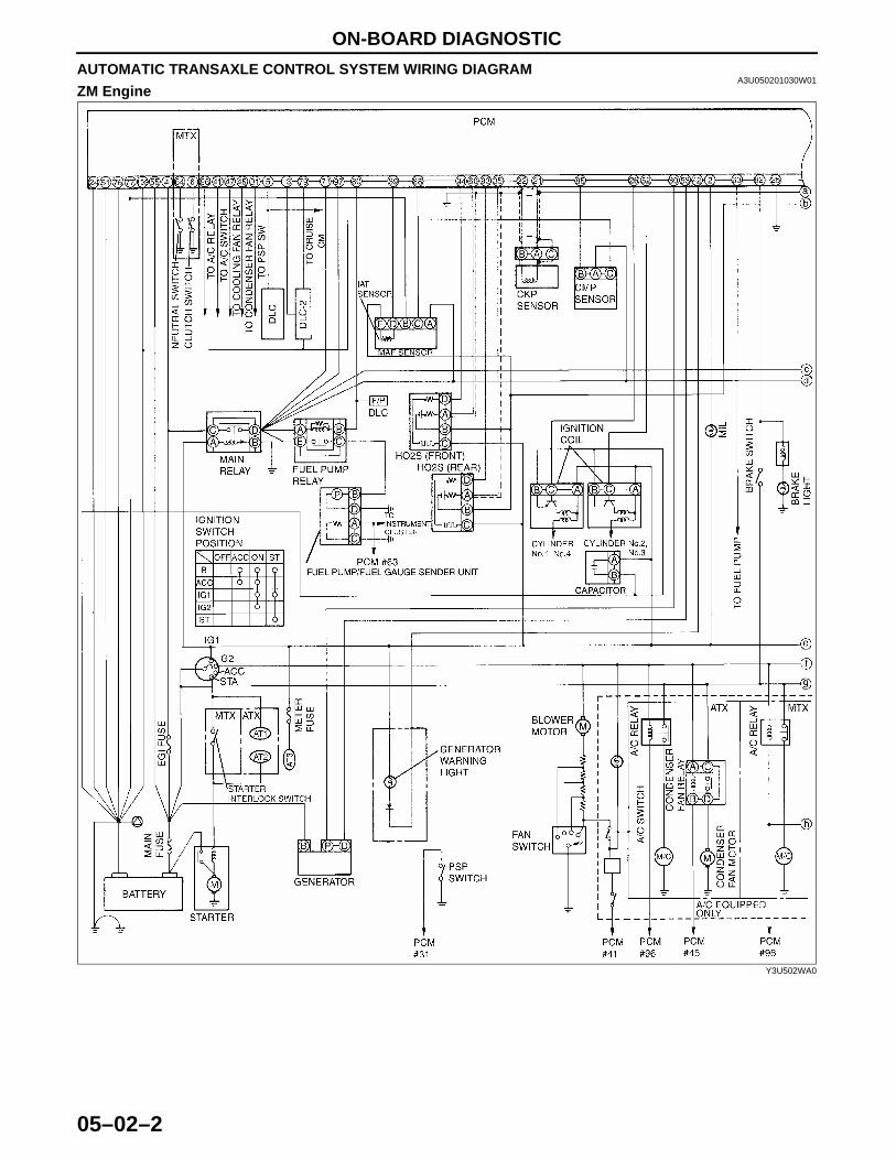
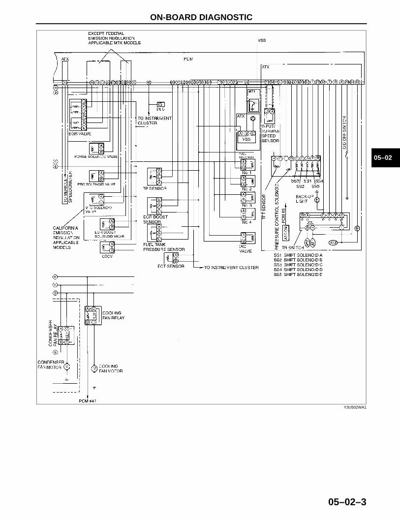
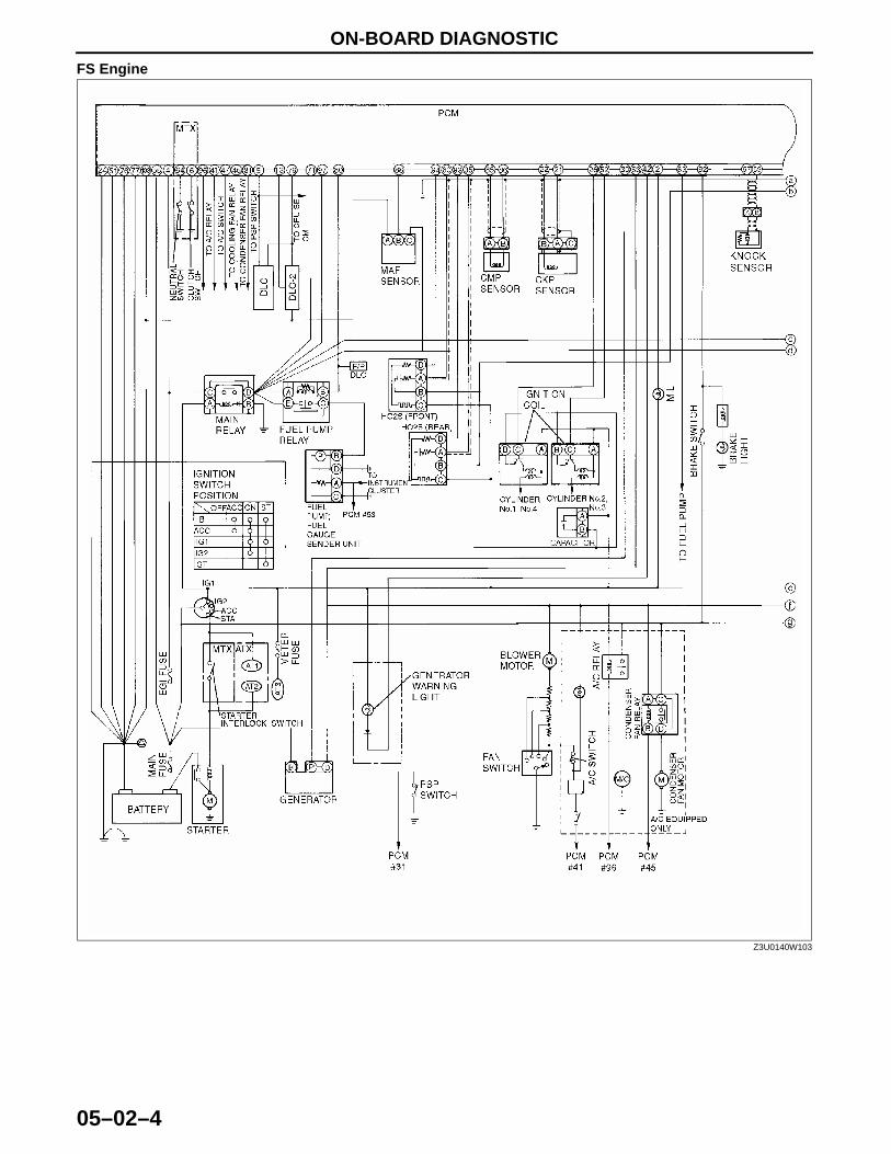
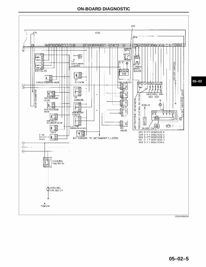
AUTOMATIC TRANSAXLE CONTROL SYSTEM WIRING DIAGRAMA3U050201030W01
ZM Engine
Y3U502WA0
1712-1U-01G(05-02).fm 2 ページ 2001年6月29日 金曜日 午後4時35分
ON-BOARD DIAGNOSTIC
05–02–3
05–02
Y3U502WA1
1712-1U-01G(05-02).fm 3 ページ 2001年6月29日 金曜日 午後4時35分
ON-BOARD DIAGNOSTIC
05–02–4
FS Engine
Z3U0140W103
1712-1U-01G(05-02).fm 4 ページ 2001年6月29日 金曜日 午後4時35分
ON-BOARD DIAGNOSTIC
05–02–5
05–02
End Of Sie
Z3U0140W104
1712-1U-01G(05-02).fm 5 ページ 2001年6月29日 金曜日 午後4時35分

ON-BOARD DIAGNOSTIC
05–02–6
FOREWARDA3U050201030W02
• When the customer reports a vehicle malfunction, check the malfunction indicator lamp (MIL), O/D OFF indicator light flashing, and PCM memory for diagnostic trouble code (DTC), then diagnose the malfunction according to following flowchart.— If the DTC exists, diagnose the applicable DTC. (See 05–02–7 DTC TABLE.)— If the DTC does not exist, MIL does not illuminate, and O/D OFF indicator light flashes, diagnose the
applicable symptom troubleshooting. (See 05–03–7 AUTOMATIC TRANSAXLE SYMPTOM TROUBLESHOOTING ITEM TABLE.)
*:Malfunction indicator lamp (MIL), O/D OFF indicator lightEnd Of SieAUTOMATIC TRANSAXLE ON-BOARD DIAGNOSTIC FUNCTION
A3U050201030W03DTC Reading Procedure(See 01–02A–8 DTCs Retrieving Procedure.)(See 01–02B–7 DTCs Retrieving Procedure.)End Of SieAFTER REPAIR PROCEDURE
A3U050201030W04
Caution•••• After repairing a malfunction, perform this procedure to verify that the malfunction has been
corrected.•••• When this procedure is carried out, be sure to drive the vehicle at lawful speed and pay attention
to the other vehicles.
1. Connect the WDS or equivalent to the DLC-2.2. Turn the ignition key to ON (engine OFF).3. Verify that DTCs are cleared from memory.4. Decrease ATF temperature to 20 °°°°C {68 °°°°F} or below.5. Start the engine then wait 180 seconds or more.6. Warm up the engine and ATX.
• Engine coolant temperature: 60 °°°°C {140 °°°°F} or above.• Transaxle fluid temperature: 20 °°°°C {68 °°°°F} or above.
7. Shift the selector lever between P position to 1 range while depressing brake pedal.8. Drive the vehicle for 150 seconds or more at a vehicle speed between 25 and 59 km/h {15 and 36 mph},
then 60 km/h {37 mph} or more for 100 seconds or more.9. Drive the vehicle in D range and shift gears between 1st and 4th (TCC operation) gear.
10. Gradually slow down and stop the vehicle.
YMU102WBX
1712-1U-01G(05-02).fm 6 ページ 2001年6月29日 金曜日 午後4時35分
ON-BOARD DIAGNOSTIC
05–02–7
05–02
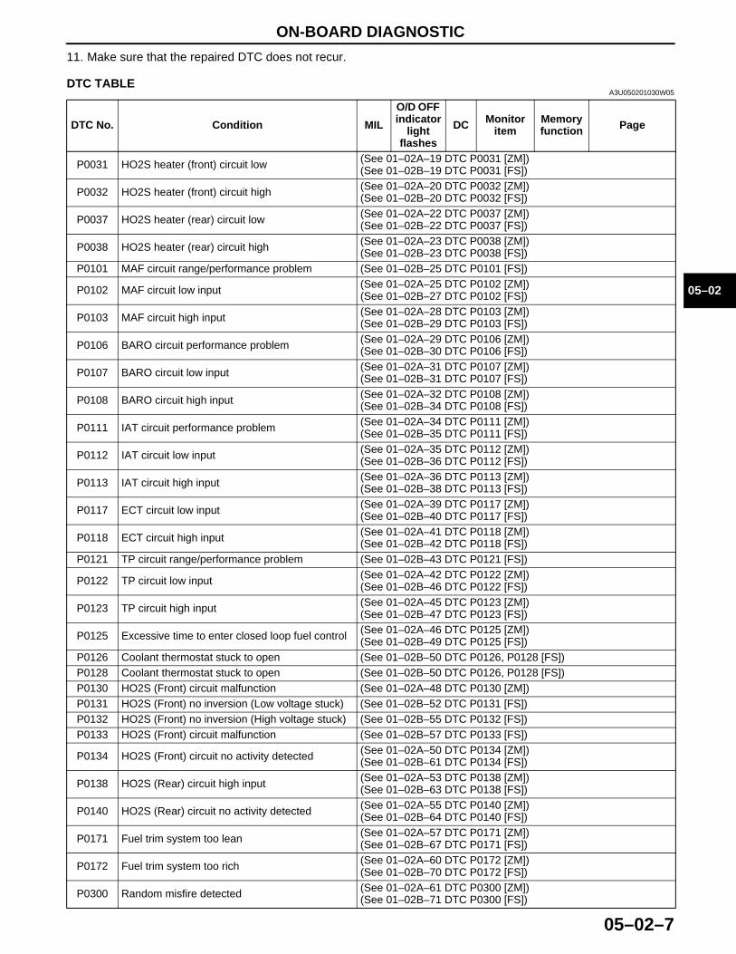
11. Make sure that the repaired DTC does not recur.End Of SieDTC TABLE
A3U050201030W05
DTC No. Condition MIL
O/D OFF indicator
light flashes
DC Monitor item
Memory function Page
P0031 HO2S heater (front) circuit low (See 01–02A–19 DTC P0031 [ZM])(See 01–02B–19 DTC P0031 [FS])
P0032 HO2S heater (front) circuit high (See 01–02A–20 DTC P0032 [ZM])(See 01–02B–20 DTC P0032 [FS])
P0037 HO2S heater (rear) circuit low (See 01–02A–22 DTC P0037 [ZM])(See 01–02B–22 DTC P0037 [FS])
P0038 HO2S heater (rear) circuit high (See 01–02A–23 DTC P0038 [ZM])(See 01–02B–23 DTC P0038 [FS])
P0101 MAF circuit range/performance problem (See 01–02B–25 DTC P0101 [FS])
P0102 MAF circuit low input (See 01–02A–25 DTC P0102 [ZM])(See 01–02B–27 DTC P0102 [FS])
P0103 MAF circuit high input (See 01–02A–28 DTC P0103 [ZM])(See 01–02B–29 DTC P0103 [FS])
P0106 BARO circuit performance problem (See 01–02A–29 DTC P0106 [ZM])(See 01–02B–30 DTC P0106 [FS])
P0107 BARO circuit low input (See 01–02A–31 DTC P0107 [ZM])(See 01–02B–31 DTC P0107 [FS])
P0108 BARO circuit high input (See 01–02A–32 DTC P0108 [ZM])(See 01–02B–34 DTC P0108 [FS])
P0111 IAT circuit performance problem (See 01–02A–34 DTC P0111 [ZM])(See 01–02B–35 DTC P0111 [FS])
P0112 IAT circuit low input (See 01–02A–35 DTC P0112 [ZM])(See 01–02B–36 DTC P0112 [FS])
P0113 IAT circuit high input (See 01–02A–36 DTC P0113 [ZM])(See 01–02B–38 DTC P0113 [FS])
P0117 ECT circuit low input (See 01–02A–39 DTC P0117 [ZM])(See 01–02B–40 DTC P0117 [FS])
P0118 ECT circuit high input (See 01–02A–41 DTC P0118 [ZM])(See 01–02B–42 DTC P0118 [FS])
P0121 TP circuit range/performance problem (See 01–02B–43 DTC P0121 [FS])
P0122 TP circuit low input (See 01–02A–42 DTC P0122 [ZM])(See 01–02B–46 DTC P0122 [FS])
P0123 TP circuit high input (See 01–02A–45 DTC P0123 [ZM])(See 01–02B–47 DTC P0123 [FS])
P0125 Excessive time to enter closed loop fuel control (See 01–02A–46 DTC P0125 [ZM])(See 01–02B–49 DTC P0125 [FS])
P0126 Coolant thermostat stuck to open (See 01–02B–50 DTC P0126, P0128 [FS])P0128 Coolant thermostat stuck to open (See 01–02B–50 DTC P0126, P0128 [FS])P0130 HO2S (Front) circuit malfunction (See 01–02A–48 DTC P0130 [ZM])P0131 HO2S (Front) no inversion (Low voltage stuck) (See 01–02B–52 DTC P0131 [FS])P0132 HO2S (Front) no inversion (High voltage stuck) (See 01–02B–55 DTC P0132 [FS])P0133 HO2S (Front) circuit malfunction (See 01–02B–57 DTC P0133 [FS])
P0134 HO2S (Front) circuit no activity detected (See 01–02A–50 DTC P0134 [ZM])(See 01–02B–61 DTC P0134 [FS])
P0138 HO2S (Rear) circuit high input (See 01–02A–53 DTC P0138 [ZM])(See 01–02B–63 DTC P0138 [FS])
P0140 HO2S (Rear) circuit no activity detected (See 01–02A–55 DTC P0140 [ZM])(See 01–02B–64 DTC P0140 [FS])
P0171 Fuel trim system too lean (See 01–02A–57 DTC P0171 [ZM])(See 01–02B–67 DTC P0171 [FS])
P0172 Fuel trim system too rich (See 01–02A–60 DTC P0172 [ZM])(See 01–02B–70 DTC P0172 [FS])
P0300 Random misfire detected (See 01–02A–61 DTC P0300 [ZM])(See 01–02B–71 DTC P0300 [FS])
1712-1U-01G(05-02).fm 7 ページ 2001年6月29日 金曜日 午後4時35分
ON-BOARD DIAGNOSTIC
05–02–8
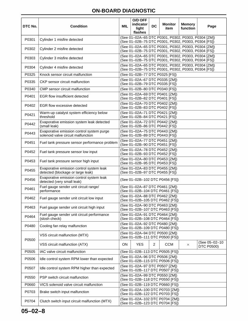
P0301 Cylinder 1 misfire detected (See 01–02A–65 DTC P0301, P0302, P0303, P0304 [ZM])(See 01–02B–75 DTC P0301, P0302, P0303, P0304 [FS])
P0302 Cylinder 2 misfire detected (See 01–02A–65 DTC P0301, P0302, P0303, P0304 [ZM])(See 01–02B–75 DTC P0301, P0302, P0303, P0304 [FS])
P0303 Cylinder 3 misfire detected (See 01–02A–65 DTC P0301, P0302, P0303, P0304 [ZM])(See 01–02B–75 DTC P0301, P0302, P0303, P0304 [FS])
P0304 Cylinder 4 misfire detected (See 01–02A–65 DTC P0301, P0302, P0303, P0304 [ZM])(See 01–02B–75 DTC P0301, P0302, P0303, P0304 [FS])
P0325 Knock sensor circuit malfunction (See 01–02B–77 DTC P0325 [FS])
P0335 CKP sensor circuit malfunction (See 01–02A–67 DTC P0335 [ZM])(See 01–02B–79 DTC P0335 [FS])
P0340 CMP sensor circuit malfunction (See 01–02B–80 DTC P0340 [FS])
P0401 EGR flow insufficient detected (See 01–02A–69 DTC P0401 [ZM])(See 01–02B–82 DTC P0401 [FS])
P0402 EGR flow excessive detected (See 01–02A–70 DTC P0402 [ZM])(See 01–02B–83 DTC P0402 [FS])
P0421 Warm-up catalyst system efficiency below threshold
(See 01–02A–71 DTC P0421 [ZM])(See 01–02B–84 DTC P0421 [FS])
P0442 Evaporative emission system leak detected (small leak)
(See 01–02A–72 DTC P0442 [ZM])(See 01–02B–86 DTC P0442 [FS])
P0443 Evaporative emission control system purge solenoid valve circuit malfunction
(See 01–02A–75 DTC P0443 [ZM])(See 01–02B–89 DTC P0443 [FS])
P0451 Fuel tank pressure sensor performance problem (See 01–02A–77 DTC P0451 [ZM])(See 01–02B–90 DTC P0451 [FS])
P0452 Fuel tank pressure sensor low input (See 01–02A–78 DTC P0452 [ZM])(See 01–02B–93 DTC P0452 [FS])
P0453 Fuel tank pressure sensor high input (See 01–02A–80 DTC P0453 [ZM])(See 01–02B–95 DTC P0453 [FS])
P0455 Evaporative emission control system leak detected (blockage or large leak)
(See 01–02A–83 DTC P0455 [ZM])(See 01–02B–97 DTC P0455 [FS])
P0456 Evaporative emission control system leak detected (very small leak) (See 01–02B–102 DTC P0456 [FS])
P0461 Fuel gauge sender unit circuit range/performance
(See 01–02A–87 DTC P0461 [ZM])(See 01–02B–104 DTC P0461 [FS])
P0462 Fuel gauge sender unit circuit low input (See 01–02A–88 DTC P0462 [ZM])(See 01–02B–105 DTC P0462 [FS])
P0463 Fuel gauge sender unit circuit high input (See 01–02A–90 DTC P0463 [ZM])(See 01–02B–107 DTC P0463 [FS])
P0464 Fuel gauge sender unit circuit performance (slosh check)
(See 01–02A–91 DTC P0464 [ZM])(See 01–02B–108 DTC P0464 [FS])
P0480 Cooling fan relay malfunction (See 01–02A–92 DTC P0480 [ZM])(See 01–02B–109 DTC P0480 [FS])
P0500VSS circuit malfunction (MTX) (See 01–02A–94 DTC P0500 [ZM])
(See 01–02B–111 DTC P0500 [FS])
VSS circuit malfunction (ATX) ON YES 2 CCM × (See 05–02–10 DTC P0500)
P0505 IAC valve circuit malfunction (See 01–02B–113 DTC P0505 [FS])
P0506 Idle control system RPM lower than expected (See 01–02A–96 DTC P0506 [ZM])(See 01–02B–115 DTC P0506 [FS])
P0507 Idle control system RPM higher than expected (See 01–02A–97 DTC P0507 [ZM])(See 01–02B–117 DTC P0507 [FS])
P0550 PSP switch circuit malfunction (See 01–02A–99 DTC P0550 [ZM])(See 01–02B–118 DTC P0550 [FS])
P0660 VICS solenoid valve circuit malfunction (See 01–02B–119 DTC P0660 [FS])
P0703 Brake switch input malfunction (See 01–02A–100 DTC P0703 [ZM])(See 01–02B–122 DTC P0703 [FS])
P0704 Clutch switch input circuit malfunction (MTX) (See 01–02A–102 DTC P0704 [ZM])(See 01–02B–123 DTC P0704 [FS])
DTC No. Condition MIL
O/D OFF indicator
light flashes
DC Monitor item
Memory function Page
1712-1U-01G(05-02).fm 8 ページ 2001年6月29日 金曜日 午後4時35分
ON-BOARD DIAGNOSTIC
05–02–9
05–02
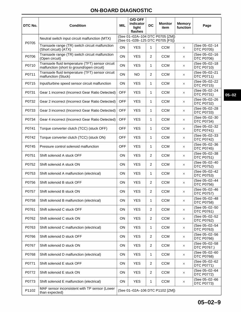
P0705Neutral switch input circuit malfunction (MTX) (See 01–02A–104 DTC P0705 [ZM])
(See 01–02B–125 DTC P0705 [FS])Transaxle range (TR) switch circuit malfunction (Short circuit) (ATX) ON YES 1 CCM × (See 05–02–14
DTC P0705)
P0706 Transaxle range (TR) switch circuit malfunction (Open circuit) ON YES 2 CCM × (See 05–02–16
DTC P0706)
P0710 Transaxle fluid temperature (TFT) sensor circuit malfunction (short to ground/open circuit) ON YES 1 CCM × (See 05–02–18
DTC P0710)
P0711 Transaxle fluid temperature (TFT) sensor circuit malfunction (Stuck) ON NO 2 CCM × (See 05–02–21
DTC P0711)
P0715 Input/turbine speed sensor circuit malfunction ON YES 1 CCM × (See 05–02–22 DTC P0715)
P0731 Gear 1 incorrect (Incorrect Gear Ratio Detected) OFF YES 1 CCM × (See 05–02–24 DTC P0731)
P0732 Gear 2 incorrect (Incorrect Gear Ratio Detected) OFF YES 1 CCM × (See 05–02–26 DTC P0732)
P0733 Gear 3 incorrect (Incorrect Gear Ratio Detected) OFF YES 1 CCM × (See 05–02–28 DTC P0733)
P0734 Gear 4 incorrect (Incorrect Gear Ratio Detected) OFF YES 1 CCM × (See 05–02–30 DTC P0734)
P0741 Torque converter clutch (TCC) (stuck OFF) OFF YES 1 CCM × (See 05–02–32 DTC P0741)
P0742 Torque converter clutch (TCC) (stuck ON) OFF YES 1 CCM × (See 05–02–33 DTC P0742)
P0745 Pressure control solenoid malfunction OFF YES 1 CCM × (See 05–02–36 DTC P0745)
P0751 Shift solenoid A stuck OFF ON YES 2 CCM × (See 05–02–38 DTC P0751)
P0752 Shift solenoid A stuck ON ON YES 2 CCM × (See 05–02–40 DTC P0752)
P0753 Shift solenoid A malfunction (electrical) ON YES 1 CCM × (See 05–02–42 DTC P0753)
P0756 Shift solenoid B stuck OFF ON YES 2 CCM × (See 05–02–44 DTC P0756)
P0757 Shift solenoid B stuck ON ON YES 2 CCM × (See 05–02–46 DTC P0757)
P0758 Shift solenoid B malfunction (electrical) ON YES 1 CCM × (See 05–02–48 DTC P0758)
P0761 Shift solenoid C stuck OFF ON YES 2 CCM × (See 05–02–50 DTC P0761)
P0762 Shift solenoid C stuck ON ON YES 2 CCM × (See 05–02–52 DTC P0762)
P0763 Shift solenoid C malfunction (electrical) ON YES 1 CCM × (See 05–02–54 DTC P0763)
P0766 Shift solenoid D stuck OFF ON YES 2 CCM × (See 05–02–56 DTC P0766)
P0767 Shift solenoid D stuck ON ON YES 2 CCM × (See 05–02–58 DTC P0767.)
P0768 Shift solenoid D malfunction (electrical) ON YES 1 CCM × (See 05–02–60 DTC P0768)
P0771 Shift solenoid E stuck OFF ON YES 2 CCM × (See 05–02–62 DTC P0771)
P0772 Shift solenoid E stuck ON ON YES 2 CCM × (See 05–02–64 DTC P0772)
P0773 Shift solenoid E malfunction (electrical) ON YES 1 CCM × (See 05–02–66 DTC P0773)
P1102 MAF sensor inconsistent with TP sensor (Lower than expected) (See 01–02A–106 DTC P1102 [ZM])
DTC No. Condition MIL
O/D OFF indicator
light flashes
DC Monitor item
Memory function Page
1712-1U-01G(05-02).fm 9 ページ 2001年6月29日 金曜日 午後4時35分
ON-BOARD DIAGNOSTIC
05–02–10
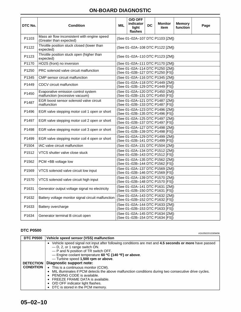
End Of SieDTC P0500
A3U050201030W06
P1103 Mass air flow inconsistent with engine speed (Greater than expected) (See 01–02A–107 DTC P1103 [ZM])
P1122 Throttle position stuck closed (lower than expected) (See 01–02A–108 DTC P1122 [ZM])
P1123 Throttle position stuck open (higher than expected) (See 01–02A–110 DTC P1123 [ZM])
P1170 HO2S (front) no inversion (See 01–02A–111 DTC P1170 [ZM])
P1250 PRC solenoid valve circuit malfunction (See 01–02A–114 DTC P1250 [ZM])(See 01–02B–127 DTC P1250 [FS])
P1345 CMP sensor circuit malfunction (See 01–02A–116 DTC P1345 [ZM])
P1449 CDCV circuit malfunction (See 01–02A–118 DTC P1449 [ZM])(See 01–02B–129 DTC P1449 [FS])
P1450 Evaporative emission control system malfunction (excessive vacuum)
(See 01–02A–120 DTC P1450 [ZM])(See 01–02B–131 DTC P1450 [FS])
P1487 EGR boost sensor solenoid valve circuit malfunction
(See 01–02A–121 DTC P1487 [ZM])(See 01–02B–133 DTC P1487 [FS])
P1496 EGR valve stepping motor coil 1 open or short (See 01–02A–123 DTC P1496 [ZM])(See 01–02B–135 DTC P1496 [FS])
P1497 EGR valve stepping motor coil 2 open or short (See 01–02A–125 DTC P1497 [ZM])(See 01–02B–137 DTC P1497 [FS])
P1498 EGR valve stepping motor coil 3 open or short (See 01–02A–127 DTC P1498 [ZM])(See 01–02B–139 DTC P1498 [FS])
P1499 EGR valve stepping motor coil 4 open or short (See 01–02A–129 DTC P1499 [ZM])(See 01–02B–141 DTC P1499 [FS])
P1504 IAC valve circuit malfunction (See 01–02A–131 DTC P1504 [ZM])
P1512 VTCS shutter valve close stuck (See 01–02A–134 DTC P1512 [ZM])(See 01–02B–143 DTC P1512 [FS])
P1562 PCM +BB voltage low (See 01–02A–135 DTC P1562 [ZM])(See 01–02B–144 DTC P1562 [FS])
P1569 VTCS solenoid valve circuit low input (See 01–02A–137 DTC P1569 [ZM])(See 01–02B–146 DTC P1569 [FS])
P1570 VTCS solenoid valve circuit high input (See 01–02A–139 DTC P1570 [ZM])(See 01–02B–148 DTC P1570 [FS])
P1631 Generator output voltage signal no electricity (See 01–02A–141 DTC P1631 [ZM])(See 01–02B–150 DTC P1631 [FS])
P1632 Battery voltage monitor signal circuit malfunction (See 01–02A–143 DTC P1632 [ZM])(See 01–02B–152 DTC P1632 [FS])
P1633 Battery overcharge (See 01–02A–144 DTC P1633 [ZM])(See 01–02B–153 DTC P1633 [FS])
P1634 Generator terminal B circuit open (See 01–02A–145 DTC P1634 [ZM])(See 01–02B–154 DTC P1634 [FS])
DTC No. Condition MIL
O/D OFF indicator
light flashes
DC Monitor item
Memory function Page
DTC P0500 Vehicle speed sensor (VSS) malfunction
DETECTION CONDITION
• Vehicle speed signal not input after following conditions are met and 4.5 seconds or more have passed— D, 2, or 1 range switch ON.— P and N position of TR switch OFF.— Engine coolant temperature 60 °°°°C {140 °°°°F} or above.— Turbine speed 1,500 rpm or above.
Diagnostic support note:• This is a continuous monitor (CCM).• MIL illuminates if PCM detects the above malfunction conditions during two consecutive drive cycles.• PENDING CODE is available.• FREEZE FRAME DATA is available.• O/D OFF indicator light flashes.• DTC is stored in the PCM memory.
1712-1U-01G(05-02).fm 10 ページ 2001年6月29日 金曜日 午後4時35分
ON-BOARD DIAGNOSTIC
05–02–11
05–02
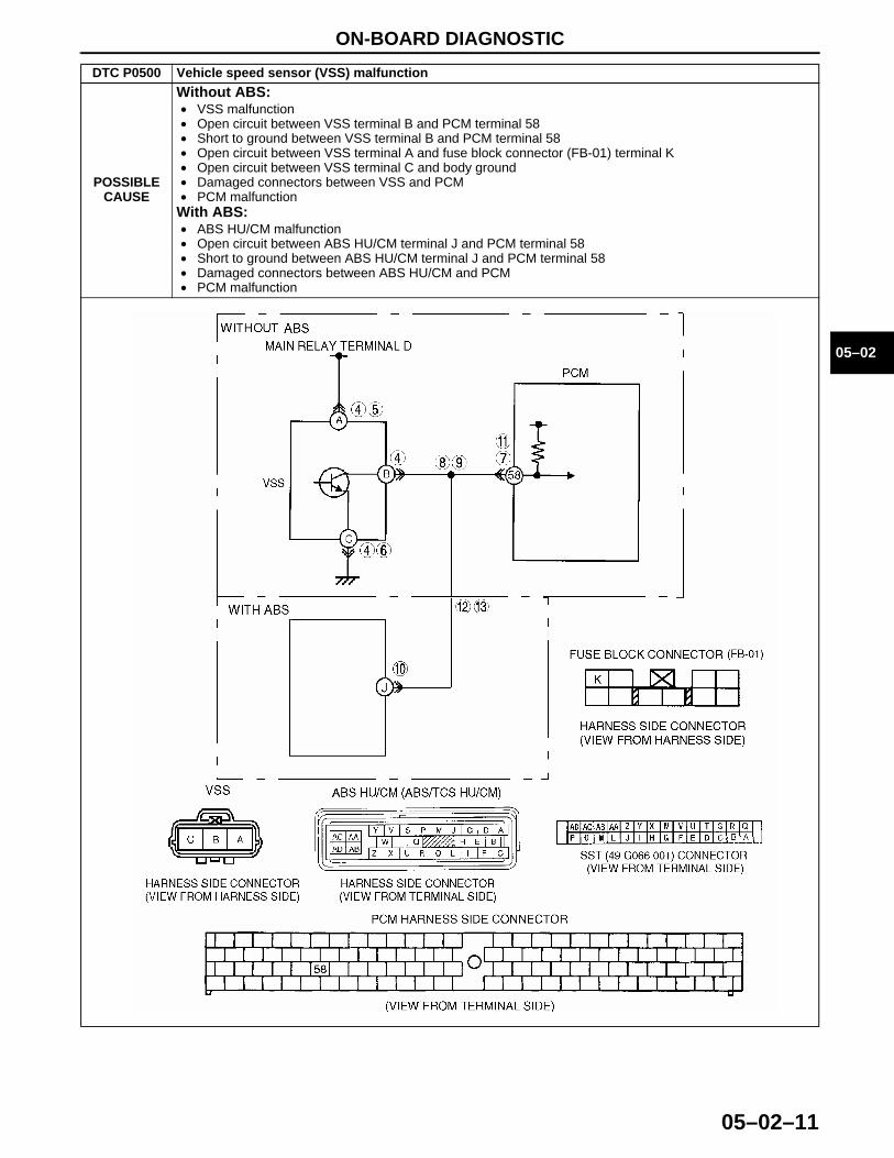
POSSIBLE CAUSE
Without ABS:• VSS malfunction• Open circuit between VSS terminal B and PCM terminal 58• Short to ground between VSS terminal B and PCM terminal 58• Open circuit between VSS terminal A and fuse block connector (FB-01) terminal K• Open circuit between VSS terminal C and body ground• Damaged connectors between VSS and PCM• PCM malfunction
With ABS:• ABS HU/CM malfunction• Open circuit between ABS HU/CM terminal J and PCM terminal 58• Short to ground between ABS HU/CM terminal J and PCM terminal 58• Damaged connectors between ABS HU/CM and PCM• PCM malfunction
DTC P0500 Vehicle speed sensor (VSS) malfunction
1712-1U-01G(05-02).fm 11 ページ 2001年6月29日 金曜日 午後4時35分
ON-BOARD DIAGNOSTIC
05–02–12
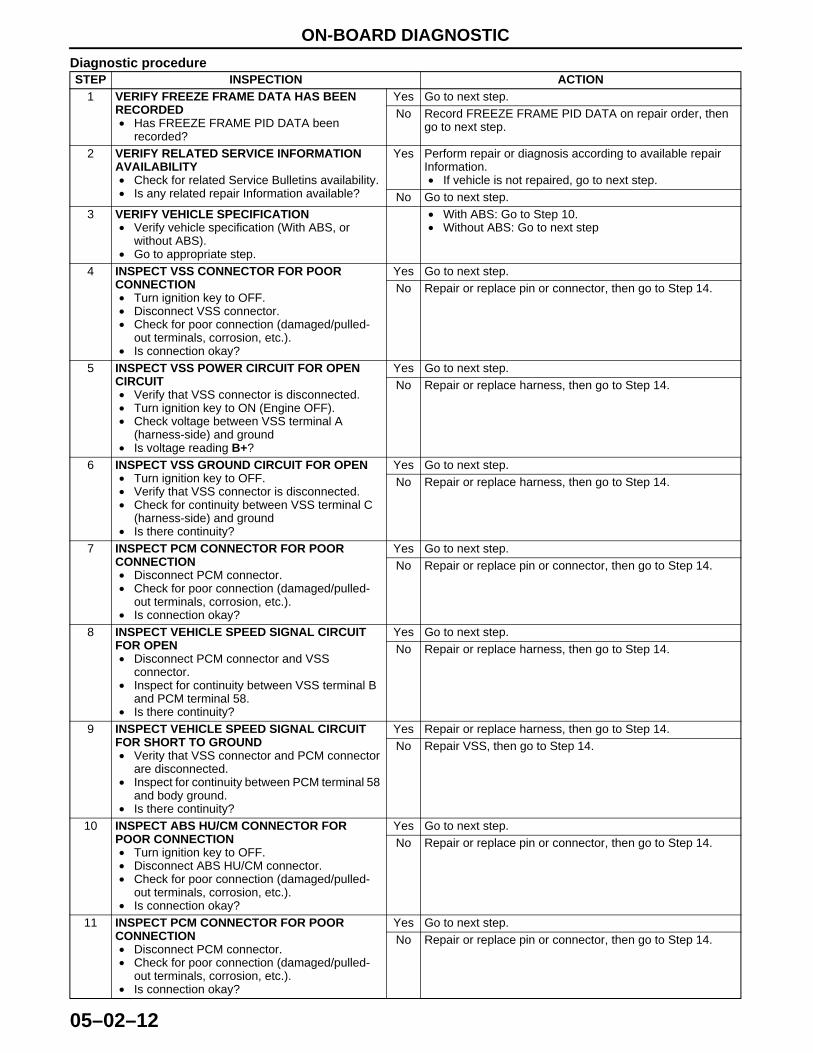
Diagnostic procedureSTEP INSPECTION ACTION
1 VERIFY FREEZE FRAME DATA HAS BEEN RECORDED• Has FREEZE FRAME PID DATA been
recorded?
Yes Go to next step.No Record FREEZE FRAME PID DATA on repair order, then
go to next step.
2 VERIFY RELATED SERVICE INFORMATION AVAILABILITY• Check for related Service Bulletins availability.• Is any related repair Information available?
Yes Perform repair or diagnosis according to available repair Information.• If vehicle is not repaired, go to next step.
No Go to next step.3 VERIFY VEHICLE SPECIFICATION
• Verify vehicle specification (With ABS, or without ABS).
• Go to appropriate step.
• With ABS: Go to Step 10.• Without ABS: Go to next step
4 INSPECT VSS CONNECTOR FOR POOR CONNECTION• Turn ignition key to OFF.• Disconnect VSS connector.• Check for poor connection (damaged/pulled-
out terminals, corrosion, etc.).• Is connection okay?
Yes Go to next step.No Repair or replace pin or connector, then go to Step 14.
5 INSPECT VSS POWER CIRCUIT FOR OPEN CIRCUIT• Verify that VSS connector is disconnected.• Turn ignition key to ON (Engine OFF).• Check voltage between VSS terminal A
(harness-side) and ground• Is voltage reading B+?
Yes Go to next step.No Repair or replace harness, then go to Step 14.
6 INSPECT VSS GROUND CIRCUIT FOR OPEN• Turn ignition key to OFF.• Verify that VSS connector is disconnected.• Check for continuity between VSS terminal C
(harness-side) and ground• Is there continuity?
Yes Go to next step.No Repair or replace harness, then go to Step 14.
7 INSPECT PCM CONNECTOR FOR POOR CONNECTION• Disconnect PCM connector.• Check for poor connection (damaged/pulled-
out terminals, corrosion, etc.).• Is connection okay?
Yes Go to next step.No Repair or replace pin or connector, then go to Step 14.
8 INSPECT VEHICLE SPEED SIGNAL CIRCUIT FOR OPEN• Disconnect PCM connector and VSS
connector.• Inspect for continuity between VSS terminal B
and PCM terminal 58.• Is there continuity?
Yes Go to next step.No Repair or replace harness, then go to Step 14.
9 INSPECT VEHICLE SPEED SIGNAL CIRCUIT FOR SHORT TO GROUND• Verity that VSS connector and PCM connector
are disconnected.• Inspect for continuity between PCM terminal 58
and body ground.• Is there continuity?
Yes Repair or replace harness, then go to Step 14.No Repair VSS, then go to Step 14.
10 INSPECT ABS HU/CM CONNECTOR FOR POOR CONNECTION• Turn ignition key to OFF.• Disconnect ABS HU/CM connector.• Check for poor connection (damaged/pulled-
out terminals, corrosion, etc.).• Is connection okay?
Yes Go to next step.No Repair or replace pin or connector, then go to Step 14.
11 INSPECT PCM CONNECTOR FOR POOR CONNECTION• Disconnect PCM connector.• Check for poor connection (damaged/pulled-
out terminals, corrosion, etc.).• Is connection okay?
Yes Go to next step.No Repair or replace pin or connector, then go to Step 14.
1712-1U-01G(05-02).fm 12 ページ 2001年6月29日 金曜日 午後4時35分
ON-BOARD DIAGNOSTIC
05–02–13
05–02
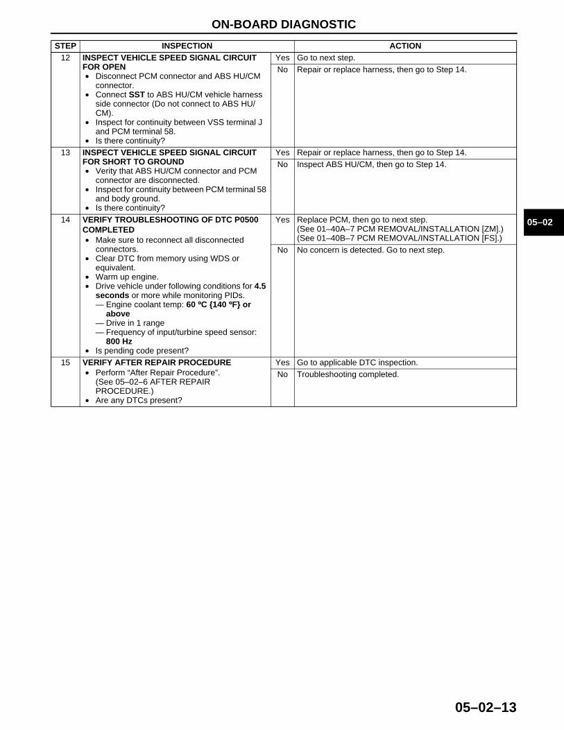
12 INSPECT VEHICLE SPEED SIGNAL CIRCUIT FOR OPEN• Disconnect PCM connector and ABS HU/CM
connector.• Connect SST to ABS HU/CM vehicle harness
side connector (Do not connect to ABS HU/CM).
• Inspect for continuity between VSS terminal J and PCM terminal 58.
• Is there continuity?
Yes Go to next step.No Repair or replace harness, then go to Step 14.
13 INSPECT VEHICLE SPEED SIGNAL CIRCUIT FOR SHORT TO GROUND• Verity that ABS HU/CM connector and PCM
connector are disconnected.• Inspect for continuity between PCM terminal 58
and body ground.• Is there continuity?
Yes Repair or replace harness, then go to Step 14.No Inspect ABS HU/CM, then go to Step 14.
14 VERIFY TROUBLESHOOTING OF DTC P0500 COMPLETED• Make sure to reconnect all disconnected
connectors.• Clear DTC from memory using WDS or
equivalent.• Warm up engine.• Drive vehicle under following conditions for 4.5
seconds or more while monitoring PIDs.— Engine coolant temp: 60 °°°°C {140 °°°°F} or
above— Drive in 1 range— Frequency of input/turbine speed sensor:
800 Hz• Is pending code present?
Yes Replace PCM, then go to next step.(See 01–40A–7 PCM REMOVAL/INSTALLATION [ZM].)(See 01–40B–7 PCM REMOVAL/INSTALLATION [FS].)
No No concern is detected. Go to next step.
15 VERIFY AFTER REPAIR PROCEDURE• Perform “After Repair Procedure”.
(See 05–02–6 AFTER REPAIR PROCEDURE.)
• Are any DTCs present?
Yes Go to applicable DTC inspection.No Troubleshooting completed.
STEP INSPECTION ACTION
1712-1U-01G(05-02).fm 13 ページ 2001年6月29日 金曜日 午後4時35分
ON-BOARD DIAGNOSTIC
05–02–14
End Of Sie
DTC P0705A3U050201030W07
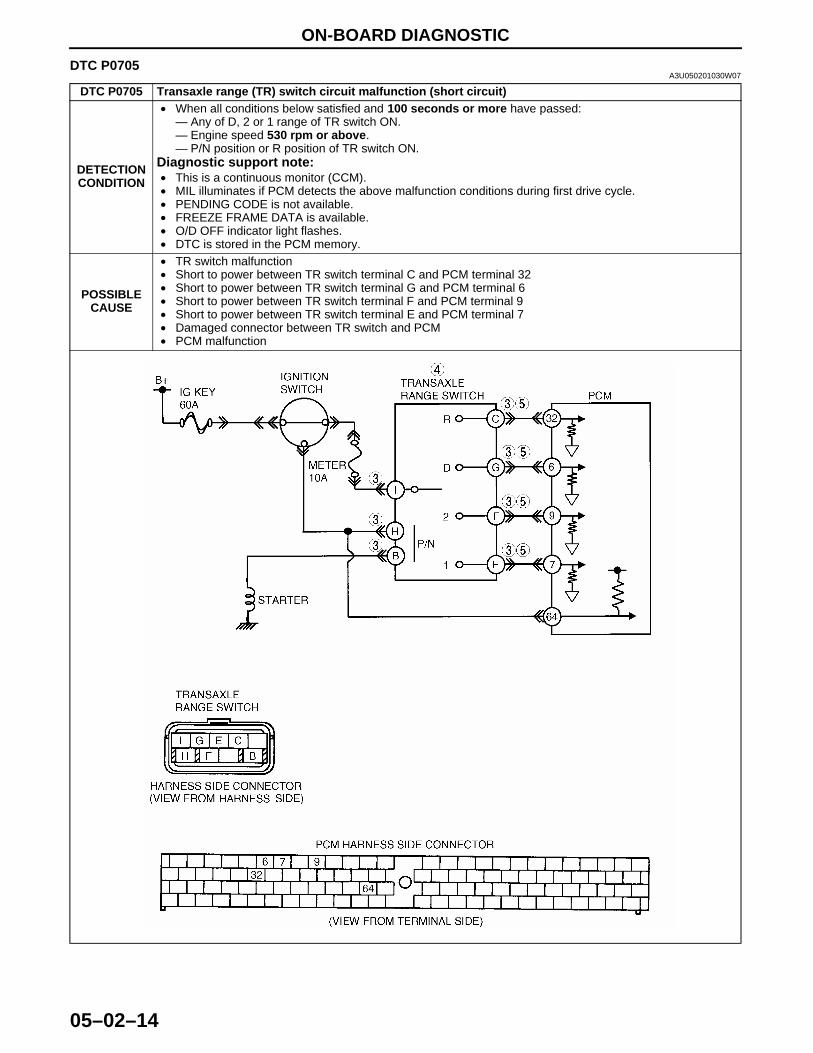
DTC P0705 Transaxle range (TR) switch circuit malfunction (short circuit)
DETECTION CONDITION
• When all conditions below satisfied and 100 seconds or more have passed:— Any of D, 2 or 1 range of TR switch ON.— Engine speed 530 rpm or above.— P/N position or R position of TR switch ON.
Diagnostic support note:• This is a continuous monitor (CCM).• MIL illuminates if PCM detects the above malfunction conditions during first drive cycle.• PENDING CODE is not available.• FREEZE FRAME DATA is available.• O/D OFF indicator light flashes.• DTC is stored in the PCM memory.
POSSIBLE CAUSE
• TR switch malfunction• Short to power between TR switch terminal C and PCM terminal 32 • Short to power between TR switch terminal G and PCM terminal 6 • Short to power between TR switch terminal F and PCM terminal 9• Short to power between TR switch terminal E and PCM terminal 7• Damaged connector between TR switch and PCM• PCM malfunction
1712-1U-01G(05-02).fm 14 ページ 2001年6月29日 金曜日 午後4時35分
ON-BOARD DIAGNOSTIC
05–02–15
05–02
Diagnostic procedure
End Of Sie
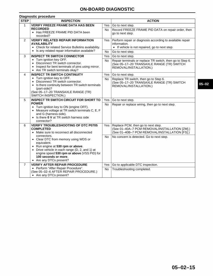
STEP INSPECTION ACTION1 VERIFY FREEZE FRAME DATA HAS BEEN
RECORDED• Has FREEZE FRAME PID DATA been
recorded?
Yes Go to next step.No Record FREEZE FRAME PID DATA on repair order, then
go to next step.
2 VERIFY RELATED REPAIR INFORMATION AVAILABILITY• Check for related Service Bulletins availability.• Is any related repair information available?
Yes Perform repair or diagnosis according to available repair information.• If vehicle is not repaired, go to next step.
No Go to next step.3 INSPECT TR SWITCH CONNECTOR
• Turn ignition key OFF.• Disconnect TR switch connector.• Inspect for bent terminals of pins using mirror.• Are TR switch terminals okay?
Yes Go to next step.No Repair terminals or replace TR switch, then go to Step 6.
(See 05–17–20 TRANSAXLE RANGE (TR) SWITCH REMOVAL/INSTALLATION.)
4 INSPECT TR SWITCH CONTINUITY• Turn ignition key to OFF.• Disconnect TR switch connector.• Is there continuity between TR switch terminals
(part-side)?(See 05–17–20 TRANSAXLE RANGE (TR) SWITCH INSPECTION.)
Yes Go to next step.No Replace TR switch, then go to Step 6.
(See 05–17–20 TRANSAXLE RANGE (TR) SWITCH REMOVAL/INSTALLATION.)
5 INSPECT TR SWITCH CIRCUIT FOR SHORT TO POWER• Turn ignition key to ON (engine OFF).• Measure voltage at TR switch terminals C, E, F
and G (harness-side).• Is there 0 V at TR switch harness side
connector?
Yes Go to next step.No Repair or replace wiring, then go to next step.
6 VERIFY TROUBLESHOOTING OF DTC P0705 COMPLETED• Make sure to reconnect all disconnected
connectors.• Clear DTC from memory using WDS or
equivalent.• Run engine at 530 rpm or above.• Drive vehicle in each range (D, 2, and 1) at
engine speed 530 rpm or above (VSS PID) for 100 seconds or more.
• Are any DTCs present?
Yes Replace PCM, then go to next step.(See 01–40A–7 PCM REMOVAL/INSTALLATION [ZM].)(See 01–40B–7 PCM REMOVAL/INSTALLATION [FS].)
No No concern is detected. Go to next step.
7 VERIFY AFTER REPAIR PROCEDURE• Perform “After Repair Procedure”.
(See 05–02–6 AFTER REPAIR PROCEDURE.)• Are any DTCs present?
Yes Go to applicable DTC inspection.No Troubleshooting completed.
1712-1U-01G(05-02).fm 15 ページ 2001年6月29日 金曜日 午後4時35分
ON-BOARD DIAGNOSTIC
05–02–16
DTC P0706A3U050201030W08
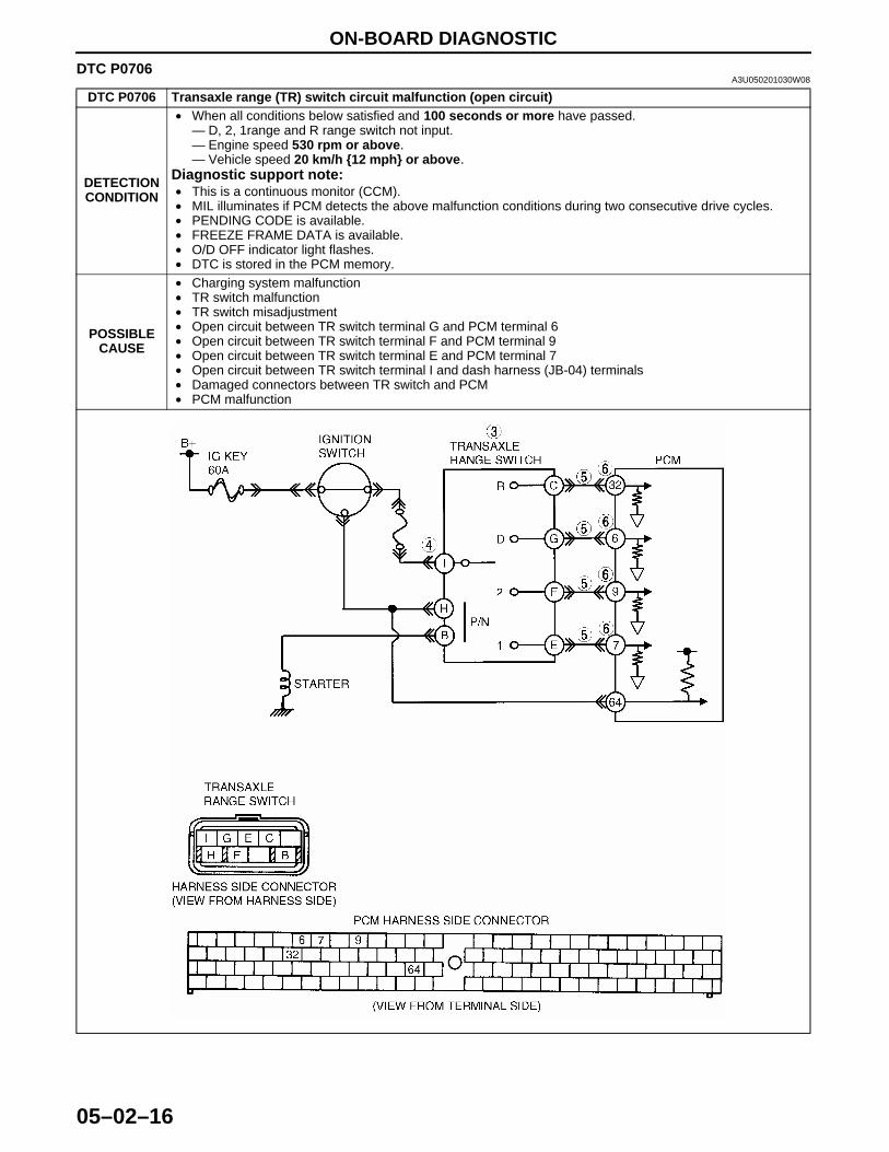
DTC P0706 Transaxle range (TR) switch circuit malfunction (open circuit)
DETECTION CONDITION
• When all conditions below satisfied and 100 seconds or more have passed.— D, 2, 1range and R range switch not input.— Engine speed 530 rpm or above.— Vehicle speed 20 km/h {12 mph} or above.
Diagnostic support note:• This is a continuous monitor (CCM).• MIL illuminates if PCM detects the above malfunction conditions during two consecutive drive cycles.• PENDING CODE is available.• FREEZE FRAME DATA is available.• O/D OFF indicator light flashes.• DTC is stored in the PCM memory.
POSSIBLE CAUSE
• Charging system malfunction• TR switch malfunction• TR switch misadjustment• Open circuit between TR switch terminal G and PCM terminal 6• Open circuit between TR switch terminal F and PCM terminal 9 • Open circuit between TR switch terminal E and PCM terminal 7 • Open circuit between TR switch terminal I and dash harness (JB-04) terminals• Damaged connectors between TR switch and PCM• PCM malfunction
1712-1U-01G(05-02).fm 16 ページ 2001年6月29日 金曜日 午後4時35分

ON-BOARD DIAGNOSTIC
05–02–17
05–02
Diagnostic procedure
End Of Sie
STEP INSPECTION ACTION1 VERIFY FREEZE FRAME DATA HAS BEEN
RECORDED• Has FREEZE FRAME PID DATA been
recorded?
Yes Go to next step.No Record FREEZE FRAME PID DATA on repair order, then
go to next step.
2 VERIFY RELATED REPAIR INFORMATION AVAILABILITY• Check for related Service Bulletins availability.• Is any related repair information available?
Yes Perform repair or diagnosis according to available repair information.• If vehicle is not repaired, go to next step.
No Go to next step.3 INSPECT TR SWITCH FOR OPEN
• Turn ignition key to OFF.• Disconnect TR switch connector.• Inspect for continuity between TR switch
terminals (part-side).— D range: I and G— 2 range: I and F— 1 range: I and E— R range: I and C
• Is there continuity between TR switch terminals (part-side)?
(See 05–17–20 TRANSAXLE RANGE (TR) SWITCH INSPECTION.)
Yes Go to next step.No Replace TR switch, then go to Step 7.
(See 05–17–20 TRANSAXLE RANGE (TR) SWITCH REMOVAL/INSTALLATION.)
4 INSPECT TR SWITCH POWER CIRCUIT FOR OPEN• Turn ignition key to ON.• Inspect voltage at TR switch terminal I
(harness-side).• Is there B+ at TR switch terminal I (harness-
side)?
Yes Go to next step.No Inspect main fuse.
• If okay, repair or replace wiring, then go to Step 7.
5 INSPECT PCM CONNECTOR FOR POOR CONNECTION• Turn ignition key to OFF.• Check for poor connection (damaged/pulled-
out terminals, corrosion, etc.).• Is connection okay?
Yes Go to next step.No Repair or replace connector and/or terminals, then go to
Step 7.
6 INSPECT TR SWITCH SIGNAL CIRCUIT FOR OPEN• Inspect for continuity between TR switch
terminals (harness-side) and PCM terminals (harness-side).— D range: G to 6— 2 range: F to 9— 1 range: E to 7— R range: C to 32
• Is there continuity?
Yes Go to next step.No Repair or replace harness, then go to next step.
7 VERIFY TROUBLESHOOTING OF DTC P0706 COMPLETED• Make sure to reconnect all disconnected
connectors.• Clear DTC from memory using WDS or
equivalent.• Drive vehicle in each range (D, 2, 1, and R) for
100 seconds or more under following conditions.— Engine speed (RPM PID) 530 rpm or
above— Vehicle speed (VSS PID) 20 km/h {12 mph}
or above• Is pending code present?
Yes Replace PCM, then go to next step.(See 01–40A–7 PCM REMOVAL/INSTALLATION [ZM].)(See 01–40B–7 PCM REMOVAL/INSTALLATION [FS].)
No No concern is detected. Go to next step.
8 VERIFY AFTER REPAIR PROCEDURE• Perform “After Repair Procedure”.
(See 05–02–6 AFTER REPAIR PROCEDURE.)• Are any DTCs present?
Yes Go to applicable DTC inspection.No Troubleshooting completed.
1712-1U-01G(05-02).fm 17 ページ 2001年6月29日 金曜日 午後4時35分
ON-BOARD DIAGNOSTIC
05–02–18
DTC P0710A3U050201030W09
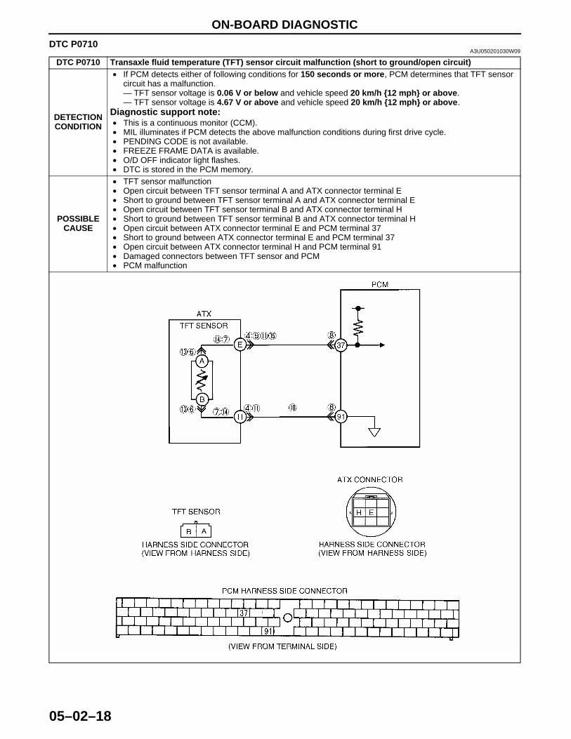
DTC P0710 Transaxle fluid temperature (TFT) sensor circuit malfunction (short to ground/open circuit)
DETECTION CONDITION
• If PCM detects either of following conditions for 150 seconds or more, PCM determines that TFT sensor circuit has a malfunction.— TFT sensor voltage is 0.06 V or below and vehicle speed 20 km/h {12 mph} or above.— TFT sensor voltage is 4.67 V or above and vehicle speed 20 km/h {12 mph} or above.
Diagnostic support note:• This is a continuous monitor (CCM).• MIL illuminates if PCM detects the above malfunction conditions during first drive cycle.• PENDING CODE is not available.• FREEZE FRAME DATA is available.• O/D OFF indicator light flashes.• DTC is stored in the PCM memory.
POSSIBLE CAUSE
• TFT sensor malfunction• Open circuit between TFT sensor terminal A and ATX connector terminal E• Short to ground between TFT sensor terminal A and ATX connector terminal E• Open circuit between TFT sensor terminal B and ATX connector terminal H• Short to ground between TFT sensor terminal B and ATX connector terminal H• Open circuit between ATX connector terminal E and PCM terminal 37• Short to ground between ATX connector terminal E and PCM terminal 37• Open circuit between ATX connector terminal H and PCM terminal 91• Damaged connectors between TFT sensor and PCM• PCM malfunction
1712-1U-01G(05-02).fm 18 ページ 2001年6月29日 金曜日 午後4時35分
ON-BOARD DIAGNOSTIC
05–02–19
05–02
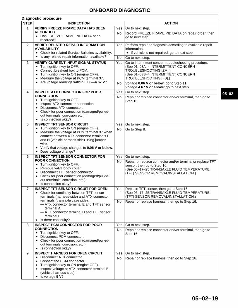
Diagnostic procedureSTEP INSPECTION ACTION
1 VERIFY FREEZE FRAME DATA HAS BEEN RECORDED• Has FREEZE FRAME PID DATA been
recorded?
Yes Go to next step.No Record FREEZE FRAME PID DATA on repair order, then
go to next step.
2 VERIFY RELATED REPAIR INFORMATION AVAILABILITY• Check for related Service Bulletins availability.• Is any related repair information available?
Yes Perform repair or diagnosis according to available repair information.• If vehicle is not repaired, go to next step.
No Go to next step.3 VERIFY CURRENT INPUT SIGNAL STATUS
• Turn ignition key to OFF.• Connect breakout box to PCM.• Turn ignition key to ON (engine OFF).• Measure the voltage at PCM terminal 37.• Are voltage readings within 0.06—4.67 V?
Yes Go to intermittent concern troubleshooting procedure.(See 01–03A–4 INTERMITTENT CONCERN TROUBLESHOOTING [ZM].)(See 01–03B–4 INTERMITTENT CONCERN TROUBLESHOOTING [FS].)
No Voltage 0.06 V or below: go to Step 11.Voltage 4.67 V or above: go to next step.
4 INSPECT ATX CONNECTOR FOR POOR CONNECTION• Turn ignition key to OFF.• Inspect ATX connector connection.• Disconnect ATX connector.• Check for poor connection (damaged/pulled-
out terminals, corrosion etc.).• Is connection okay?
Yes Go to next step.No Repair or replace connector and/or terminal, then go to
Step 16.
5 INSPECT TFT SENSOR CIRCUIT• Turn ignition key to ON (engine OFF).• Measure the voltage at PCM terminal 37 when
connect between ATX connector terminals E and H (vehicle harness-side) using jumper wire.
• Verify that voltage changes to 0.06 V or below.• Does voltage change?
Yes Go to next step.No Go to Step 8.
6 INSPECT TFT SENSOR CONNECTOR FOR POOR CONNECTION• Turn ignition key to OFF.• Remove valve body cover.• Disconnect TFT sensor connector.• Check for poor connection (damaged/pulled-
out terminals, corrosion, etc.).• Is connection okay?
Yes Go to next step.No Repair or replace connector and/or terminal or replace TFT
sensor, then go to Step 16.(See 05–17–25 TRANSAXLE FLUID TEMPERATURE (TFT) SENSOR REMOVAL/INSTALLATION.)
7 INSPECT TFT SENSOR CIRCUIT FOR OPEN• Check for continuity between TFT sensor
terminals (harness-side) and ATX connector terminals (transaxle case side).— ATX connector terminal E and TFT sensor
terminal A— ATX connector terminal H and TFT sensor
terminal B• Is there continuity?
Yes Replace TFT sensor, then go to Step 16.(See 05–17–25 TRANSAXLE FLUID TEMPERATURE (TFT) SENSOR REMOVAL/INSTALLATION.)
No Repair or replace harness, then go to Step 16.
8 INSPECT PCM CONNECTOR FOR POOR CONNECTION• Turn ignition key to OFF.• Disconnect PCM connector.• Check for poor connection (damaged/pulled-
out terminals, corrosion, etc.).• Is connection okay?
Yes Go to next step.No Repair or replace connector and/or terminal, then go to
Step 16.
9 INSPECT HARNESS FOR OPEN CIRCUIT• Disconnect ATX connector.• Connect the PCM connector.• Turn ignition key to ON (engine OFF).• Inspect voltage at ATX connector terminal E
(vehicle harness-side).• Is voltage 5 V?
Yes Go to next step.No Repair or replace harness, then go to Step 16.
1712-1U-01G(05-02).fm 19 ページ 2001年6月29日 金曜日 午後4時35分
ON-BOARD DIAGNOSTIC
05–02–20
End Of Sie
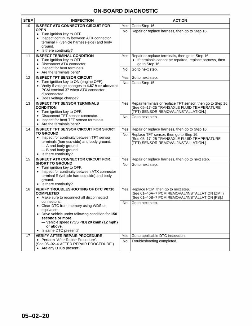
10 INSPECT ATX CONNECTOR CIRCUIT FOR OPEN• Turn ignition key to OFF.• Inspect continuity between ATX connector
terminal H (vehicle harness-side) and body ground.
• Is there continuity?
Yes Go to Step 16.No Repair or replace harness, then go to Step 16.
11 INSPECT TERMINAL CONDITION• Turn ignition key to OFF.• Disconnect ATX connector.• Inspect for bent terminals.• Are the terminals bent?
Yes Repair or replace terminals, then go to Step 16.• If terminals cannot be repaired, replace harness, then
go to Step 16.No Go to next step.
12 INSPECT TFT SENSOR CIRCUIT• Turn ignition key to ON (engine OFF).• Verify if voltage changes to 4.67 V or above at
PCM terminal 37 when ATX connector disconnected.
• Does voltage change?
Yes Go to next step.No Go to Step 15.
13 INSPECT TFT SENSOR TERMINALS CONDITION• Turn ignition key to OFF.• Disconnect TFT sensor connector.• Inspect for bent TFT sensor terminals.• Are the terminals bent?
Yes Repair terminals or replace TFT sensor, then go to Step 16.(See 05–17–25 TRANSAXLE FLUID TEMPERATURE (TFT) SENSOR REMOVAL/INSTALLATION.)
No Go to next step.
14 INSPECT TFT SENSOR CIRCUIT FOR SHORT TO GROUND• Inspect for continuity between TFT sensor
terminals (harness-side) and body ground.— A and body ground— B and body ground
• Is there continuity?
Yes Repair or replace harness, then go to Step 16.No Replace TFT sensor, then go to Step 16.
(See 05–17–25 TRANSAXLE FLUID TEMPERATURE (TFT) SENSOR REMOVAL/INSTALLATION.)
15 INSPECT ATX CONNECTOR CIRCUIT FOR SHORT TO GROUND• Turn ignition key to OFF.• Inspect for continuity between ATX connector
terminal E (vehicle harness-side) and body ground.
• Is there continuity?
Yes Repair or replace harness, then go to next step.No Go to next step.
16 VERIFY TROUBLESHOOTING OF DTC P0710 COMPLETED• Make sure to reconnect all disconnected
connectors.• Clear DTC from memory using WDS or
equivalent.• Drive vehicle under following condition for 150
seconds or more.— Vehicle speed (VSS PID) 20 km/h {12 mph}
or above.• Is same DTC present?
Yes Replace PCM, then go to next step.(See 01–40A–7 PCM REMOVAL/INSTALLATION [ZM].)(See 01–40B–7 PCM REMOVAL/INSTALLATION [FS].)
No Go to next step.
17 VERIFY AFTER REPAIR PROCEDURE• Perform “After Repair Procedure”.
(See 05–02–6 AFTER REPAIR PROCEDURE.)• Are any DTCs present?
Yes Go to applicable DTC inspection.No Troubleshooting completed.
STEP INSPECTION ACTION
1712-1U-01G(05-02).fm 20 ページ 2001年6月29日 金曜日 午後4時35分
ON-BOARD DIAGNOSTIC
05–02–21
05–02
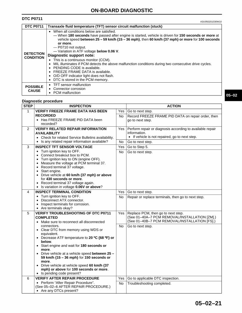
DTC P0711A3U050201030W10
Diagnostic procedure
End Of Sie
DTC P0711 Transaxle fluid temperature (TFT) sensor circuit malfunction (stuck)
DETECTION CONDITION
• When all conditions below are satisfied.— When 180 seconds have passed after engine is started, vehicle is driven for 150 seconds or more at
vehicle speed between 25 – 59 km/h {15 – 36 mph}, then 60 km/h {37 mph} or more for 100 seconds or more.
— P0710 not output.— Variation in ATF voltage below 0.06 V.
Diagnostic support note:• This is a continuous monitor (CCM).• MIL illuminates if PCM detects the above malfunction conditions during two consecutive drive cycles.• PENDING CODE is available.• FREEZE FRAME DATA is available.• O/D OFF indicator light does not flash.• DTC is stored in the PCM memory.
POSSIBLE CAUSE
• TFT sensor malfunction• Connector corrosion• PCM malfunction
STEP INSPECTION ACTION1 VERIFY FREEZE FRAME DATA HAS BEEN
RECORDED• Has FREEZE FRAME PID DATA been
recorded?
Yes Go to next step.No Record FREEZE FRAME PID DATA on repair order, then
go to next step.
2 VERIFY RELATED REPAIR INFORMATION AVAILABILITY• Check for related Service Bulletins availability.• Is any related repair information available?
Yes Perform repair or diagnosis according to available repair information.• If vehicle is not repaired, go to next step.
No Go to next step.3 INSPECT TFT SENSOR VOLTAGE
• Turn ignition key to OFF.• Connect breakout box to PCM.• Turn ignition key to ON (engine OFF).• Measure the voltage at PCM terminal 37.• Record terminal 37 voltage.• Start engine.• Drive vehicle at 60 km/h {37 mph} or above
for 430 seconds or more.• Record terminal 37 voltage again.• Is variation in voltage 0.06V or above?
Yes Go to Step 5.No Go to next step.
4 INSPECT TERMINAL CONDITION• Turn ignition key to OFF.• Disconnect ATX connector.• Inspect terminals for corrosion.• Are terminals okay?
Yes Go to next step.No Repair or replace terminals, then go to next step.
5 VERIFY TROUBLESHOOTING OF DTC P0711 COMPLETED• Make sure to reconnect all disconnected
connectors.• Clear DTC from memory using WDS or
equivalent.• Decrease ATF temperature to 20 °°°°C {68 °°°°F} or
below.• Start engine and wait for 180 seconds or
more.• Drive vehicle at a vehicle speed between 25 –
59 km/h {15 – 36 mph} for 150 seconds or more.
• Drive vehicle at vehicle speed 60 km/h {37 mph} or above for 100 seconds or more.
• Is pending code present?
Yes Replace PCM, then go to next step.(See 01–40A–7 PCM REMOVAL/INSTALLATION [ZM].)(See 01–40B–7 PCM REMOVAL/INSTALLATION [FS].)
No Go to next step.
6 VERIFY AFTER REPAIR PROCEDURE• Perform “After Repair Procedure”.
(See 05–02–6 AFTER REPAIR PROCEDURE.)• Are any DTCs present?
Yes Go to applicable DTC inspection.No Troubleshooting completed.
1712-1U-01G(05-02).fm 21 ページ 2001年6月29日 金曜日 午後4時35分
ON-BOARD DIAGNOSTIC
05–02–22
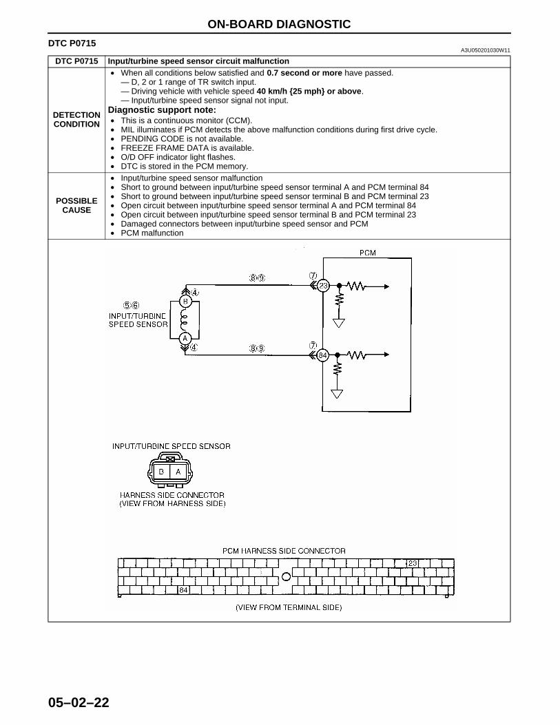
DTC P0715A3U050201030W11
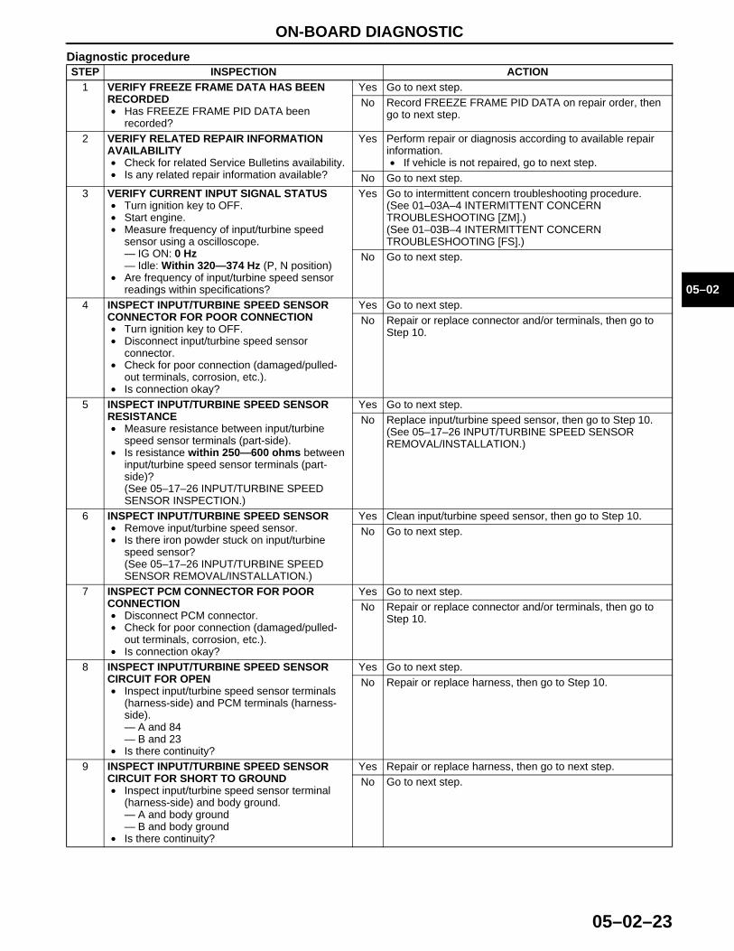
DTC P0715 Input/turbine speed sensor circuit malfunction
DETECTION CONDITION
• When all conditions below satisfied and 0.7 second or more have passed.— D, 2 or 1 range of TR switch input.— Driving vehicle with vehicle speed 40 km/h {25 mph} or above.— Input/turbine speed sensor signal not input.
Diagnostic support note:• This is a continuous monitor (CCM).• MIL illuminates if PCM detects the above malfunction conditions during first drive cycle.• PENDING CODE is not available.• FREEZE FRAME DATA is available.• O/D OFF indicator light flashes.• DTC is stored in the PCM memory.
POSSIBLE CAUSE
• Input/turbine speed sensor malfunction• Short to ground between input/turbine speed sensor terminal A and PCM terminal 84• Short to ground between input/turbine speed sensor terminal B and PCM terminal 23• Open circuit between input/turbine speed sensor terminal A and PCM terminal 84• Open circuit between input/turbine speed sensor terminal B and PCM terminal 23• Damaged connectors between input/turbine speed sensor and PCM• PCM malfunction
1712-1U-01G(05-02).fm 22 ページ 2001年6月29日 金曜日 午後4時35分
ON-BOARD DIAGNOSTIC
05–02–23
05–02
Diagnostic procedureSTEP INSPECTION ACTION
1 VERIFY FREEZE FRAME DATA HAS BEEN RECORDED• Has FREEZE FRAME PID DATA been
recorded?
Yes Go to next step.No Record FREEZE FRAME PID DATA on repair order, then
go to next step.
2 VERIFY RELATED REPAIR INFORMATION AVAILABILITY• Check for related Service Bulletins availability.• Is any related repair information available?
Yes Perform repair or diagnosis according to available repair information.• If vehicle is not repaired, go to next step.
No Go to next step.3 VERIFY CURRENT INPUT SIGNAL STATUS
• Turn ignition key to OFF.• Start engine.• Measure frequency of input/turbine speed
sensor using a oscilloscope.— IG ON: 0 Hz— Idle: Within 320—374 Hz (P, N position)
• Are frequency of input/turbine speed sensor readings within specifications?
Yes Go to intermittent concern troubleshooting procedure.(See 01–03A–4 INTERMITTENT CONCERN TROUBLESHOOTING [ZM].)(See 01–03B–4 INTERMITTENT CONCERN TROUBLESHOOTING [FS].)
No Go to next step.
4 INSPECT INPUT/TURBINE SPEED SENSOR CONNECTOR FOR POOR CONNECTION• Turn ignition key to OFF.• Disconnect input/turbine speed sensor
connector.• Check for poor connection (damaged/pulled-
out terminals, corrosion, etc.).• Is connection okay?
Yes Go to next step.No Repair or replace connector and/or terminals, then go to
Step 10.
5 INSPECT INPUT/TURBINE SPEED SENSOR RESISTANCE• Measure resistance between input/turbine
speed sensor terminals (part-side).• Is resistance within 250—600 ohms between
input/turbine speed sensor terminals (part-side)?(See 05–17–26 INPUT/TURBINE SPEED SENSOR INSPECTION.)
Yes Go to next step.No Replace input/turbine speed sensor, then go to Step 10.
(See 05–17–26 INPUT/TURBINE SPEED SENSOR REMOVAL/INSTALLATION.)
6 INSPECT INPUT/TURBINE SPEED SENSOR• Remove input/turbine speed sensor.• Is there iron powder stuck on input/turbine
speed sensor?(See 05–17–26 INPUT/TURBINE SPEED SENSOR REMOVAL/INSTALLATION.)
Yes Clean input/turbine speed sensor, then go to Step 10.No Go to next step.
7 INSPECT PCM CONNECTOR FOR POOR CONNECTION• Disconnect PCM connector.• Check for poor connection (damaged/pulled-
out terminals, corrosion, etc.).• Is connection okay?
Yes Go to next step.No Repair or replace connector and/or terminals, then go to
Step 10.
8 INSPECT INPUT/TURBINE SPEED SENSOR CIRCUIT FOR OPEN• Inspect input/turbine speed sensor terminals
(harness-side) and PCM terminals (harness-side).— A and 84— B and 23
• Is there continuity?
Yes Go to next step.No Repair or replace harness, then go to Step 10.
9 INSPECT INPUT/TURBINE SPEED SENSOR CIRCUIT FOR SHORT TO GROUND• Inspect input/turbine speed sensor terminal
(harness-side) and body ground.— A and body ground— B and body ground
• Is there continuity?
Yes Repair or replace harness, then go to next step.No Go to next step.
1712-1U-01G(05-02).fm 23 ページ 2001年6月29日 金曜日 午後4時35分
ON-BOARD DIAGNOSTIC
05–02–24
End Of SieDTC P0731
A3U050201030W12
Diagnostic procedure
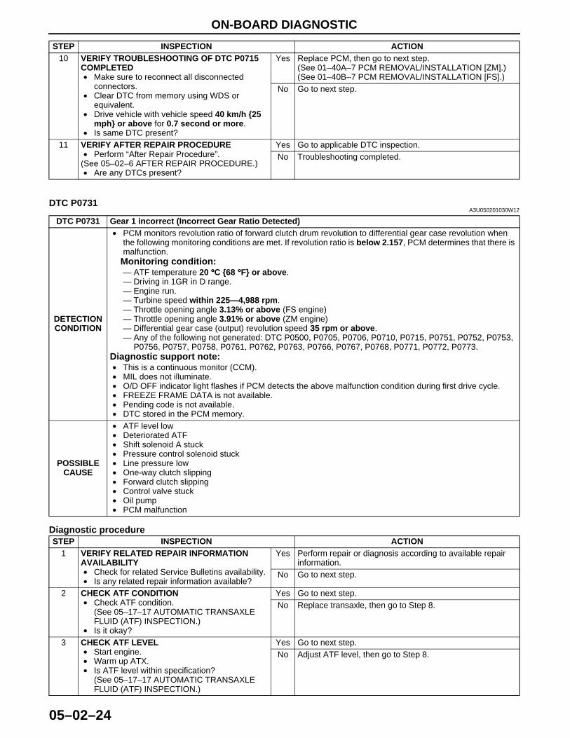
10 VERIFY TROUBLESHOOTING OF DTC P0715 COMPLETED• Make sure to reconnect all disconnected
connectors.• Clear DTC from memory using WDS or
equivalent.• Drive vehicle with vehicle speed 40 km/h {25
mph} or above for 0.7 second or more.• Is same DTC present?
Yes Replace PCM, then go to next step.(See 01–40A–7 PCM REMOVAL/INSTALLATION [ZM].)(See 01–40B–7 PCM REMOVAL/INSTALLATION [FS].)
No Go to next step.
11 VERIFY AFTER REPAIR PROCEDURE• Perform “After Repair Procedure”.
(See 05–02–6 AFTER REPAIR PROCEDURE.)• Are any DTCs present?
Yes Go to applicable DTC inspection.No Troubleshooting completed.
STEP INSPECTION ACTION
DTC P0731 Gear 1 incorrect (Incorrect Gear Ratio Detected)
DETECTION CONDITION
• PCM monitors revolution ratio of forward clutch drum revolution to differential gear case revolution when the following monitoring conditions are met. If revolution ratio is below 2.157, PCM determines that there is malfunction.
Monitoring condition:— ATF temperature 20 °°°°C {68 °°°°F} or above.— Driving in 1GR in D range.— Engine run.— Turbine speed within 225—4,988 rpm.— Throttle opening angle 3.13% or above (FS engine)— Throttle opening angle 3.91% or above (ZM engine)— Differential gear case (output) revolution speed 35 rpm or above.— Any of the following not generated: DTC P0500, P0705, P0706, P0710, P0715, P0751, P0752, P0753,
P0756, P0757, P0758, P0761, P0762, P0763, P0766, P0767, P0768, P0771, P0772, P0773.Diagnostic support note:• This is a continuous monitor (CCM).• MIL does not illuminate.• O/D OFF indicator light flashes if PCM detects the above malfunction condition during first drive cycle.• FREEZE FRAME DATA is not available.• Pending code is not available.• DTC stored in the PCM memory.
POSSIBLE CAUSE
• ATF level low• Deteriorated ATF• Shift solenoid A stuck• Pressure control solenoid stuck• Line pressure low• One-way clutch slipping• Forward clutch slipping• Control valve stuck• Oil pump• PCM malfunction
STEP INSPECTION ACTION1 VERIFY RELATED REPAIR INFORMATION
AVAILABILITY• Check for related Service Bulletins availability.• Is any related repair information available?
Yes Perform repair or diagnosis according to available repair information.
No Go to next step.
2 CHECK ATF CONDITION• Check ATF condition.
(See 05–17–17 AUTOMATIC TRANSAXLE FLUID (ATF) INSPECTION.)
• Is it okay?
Yes Go to next step.No Replace transaxle, then go to Step 8.
3 CHECK ATF LEVEL• Start engine.• Warm up ATX.• Is ATF level within specification?
(See 05–17–17 AUTOMATIC TRANSAXLE FLUID (ATF) INSPECTION.)
Yes Go to next step.No Adjust ATF level, then go to Step 8.
1712-1U-01G(05-02).fm 24 ページ 2001年6月29日 金曜日 午後4時35分
ON-BOARD DIAGNOSTIC
05–02–25
05–02
End Of Sie
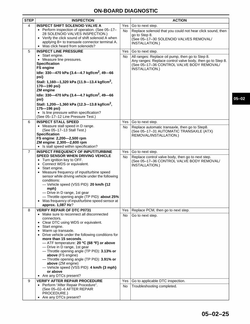
4 INSPECT SHIFT SOLENOID VALVE A • Perform inspection of operation. (See 05–17–
28 SOLENOID VALVES INSPECTION.)• Verify the click sound of shift solenoid A when
applying B+ to transaxle connector terminal A.• Was click heard from solenoids?
Yes Go to next step.No Replace solenoid that you could not hear click sound, then
go to Step 8.(See 05–17–30 SOLENOID VALVES REMOVAL/INSTALLATION.)
5 INSPECT LINE PRESSURE• Start engine.• Measure line pressures.
SpecificationFS engineIdle: 330—470 kPa {3.4—4.7 kgf/cm2, 49—66 psi}Stall: 1,160—1,320 kPa {11.9—13.4 kgf/cm2, 170—190 psi}ZM engineIdle: 330—470 kPa {3.4—4.7 kgf/cm2, 49—66 psi}Stall: 1,200—1,360 kPa {12.3—13.8 kgf/cm2, 175—196 psi}• Is line pressure within specification?
(See 05–17–12 Line Pressure Test.)
Yes Go to next step.No All ranges: Replace oil pump, then go to Step 8.
Any ranges: Replace control valve body, then go to Step 8. (See 05–17–36 CONTROL VALVE BODY REMOVAL/INSTALLATION.)
6 INSPECT STALL SPEED• Measure stall speed in D range.
(See 05–17–13 Stall Test.)SpecificationFS engine: 2,200—2,500 rpmZM engine: 2,300—2,600 rpm• Is stall speed within specification?
Yes Go to next step.No Replace automatic transaxle, then go to Step8.
(See 05–17–31 AUTOMATIC TRANSAXLE (ATX) REMOVAL/INSTALLATION.)
7 INSPECT FREQUENCY OF INPUT/TURBINE SPEED SENSOR WHEN DRIVING VEHICLE• Turn ignition key to OFF.• Connect WDS or equivalent.• Start engine.• Measure frequency of input/turbine speed
sensor while driving vehicle under the following conditions:— Vehicle speed (VSS PID): 20 km/h {12
mph}— Drive in D range, 1st gear— Throttle opening angle (TP PID): about 25%
• Was frequency of input/turbine speed sensor at approx. 1,087 Hz?
Yes Go to next step.No Replace control valve body, then go to next step.
(See 05–17–36 CONTROL VALVE BODY REMOVAL/INSTALLATION.)
8 VERIFY REPAIR OF DTC P0731• Make sure to reconnect all disconnected
connectors.• Clear DTC using WDS or equivalent.• Start engine.• Warm up transaxle.• Drive vehicle under the following conditions for
more than 15 seconds.— ATF temperature: 20 °°°°C {68 °°°°F} or above— Drive in D range, 1st gear— Throttle opening angle (TP PID): 3.13% or
above (FS engine)— Throttle opening angle (TP PID): 3.91% or
above (ZM engine)— Vehicle speed (VSS PID): 4 km/h {3 mph}
or above• Are any DTCs present?
Yes Replace PCM, then go to next step.No Go to next step.
9 VERIFY AFTER REPAIR PROCEDURE• Perform “After Repair Procedure”.
(See 05–02–6 AFTER REPAIR PROCEDURE.)
• Are any DTCs present?
Yes Go to applicable DTC inspection.No Troubleshooting completed.
STEP INSPECTION ACTION
1712-1U-01G(05-02).fm 25 ページ 2001年6月29日 金曜日 午後4時35分
ON-BOARD DIAGNOSTIC
05–02–26
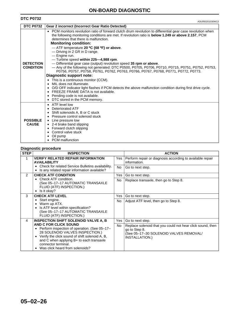
DTC P0732A3U050201030W13
Diagnostic procedure
DTC P0732 Gear 2 incorrect (Incorrect Gear Ratio Detected)
DETECTION CONDITION
• PCM monitors revolution ratio of forward clutch drum revolution to differential gear case revolution when the following monitoring conditions are met. If revolution ratio is below 1.249 or above 2.157, PCM determines that there is malfunction.
Monitoring condition:— ATF temperature 20 °°°°C {68 °°°°F} or above.— Driving in 2 GR in D range.— Engine run.— Turbine speed within 225—4,988 rpm.— Differential gear case (output) revolution speed 35 rpm or above.— Any of the following not generated: DTC P0500, P0705, P0706, P0710, P0715, P0751, P0752, P0753,
P0756, P0757, P0758, P0761, P0762, P0763, P0766, P0767, P0768, P0771, P0772, P0773.Diagnostic support note:• This is a continuous monitor (CCM).• MIL does not illuminate.• O/D OFF indicator light flashes if PCM detects the above malfunction condition during first drive cycle.• FREEZE FRAME DATA is not available.• Pending code is not available.• DTC stored in the PCM memory.
POSSIBLE CAUSE
• ATF level low• Deteriorated ATF• Shift solenoids A, B or C stuck• Pressure control solenoid stuck• Line pressure low• 2-4 brake band slipping• Forward clutch slipping• Control valve stuck• Oil pump• PCM malfunction
STEP INSPECTION ACTION1 VERIFY RELATED REPAIR INFORMATION
AVAILABILITY• Check for related Service Bulletins availability.• Is any related repair information available?
Yes Perform repair or diagnosis according to available repair information.
No Go to next step.
2 CHECK ATF CONDITION• Check ATF condition.
(See 05–17–17 AUTOMATIC TRANSAXLE FLUID (ATF) INSPECTION.)
• Is it okay?
Yes Go to next step.No Replace transaxle, then go to Step 8.
3 CHECK ATF LEVEL• Start engine.• Warm up ATX.• Is ATF level within specification?
(See 05–17–17 AUTOMATIC TRANSAXLE FLUID (ATF) INSPECTION.)
Yes Go to next step.No Adjust ATF level, then go to Step 8.
4 INSPECTION SHIFT SOLENOID VALVE A, B AND C FOR CLICK SOUND• Perform inspection of operation. (See 05–17–
28 SOLENOID VALVES INSPECTION.)• Verify the click sound of shift solenoid A, B,
and C when applying B+ to each transaxle connector terminal.
• Was click heard from solenoids?
Yes Go to next step.No Replace solenoid that you could not hear click sound, then
go to Step 8.(See 05–17–30 SOLENOID VALVES REMOVAL/INSTALLATION.)
1712-1U-01G(05-02).fm 26 ページ 2001年6月29日 金曜日 午後4時35分
ON-BOARD DIAGNOSTIC
05–02–27
05–02
End Of Sie
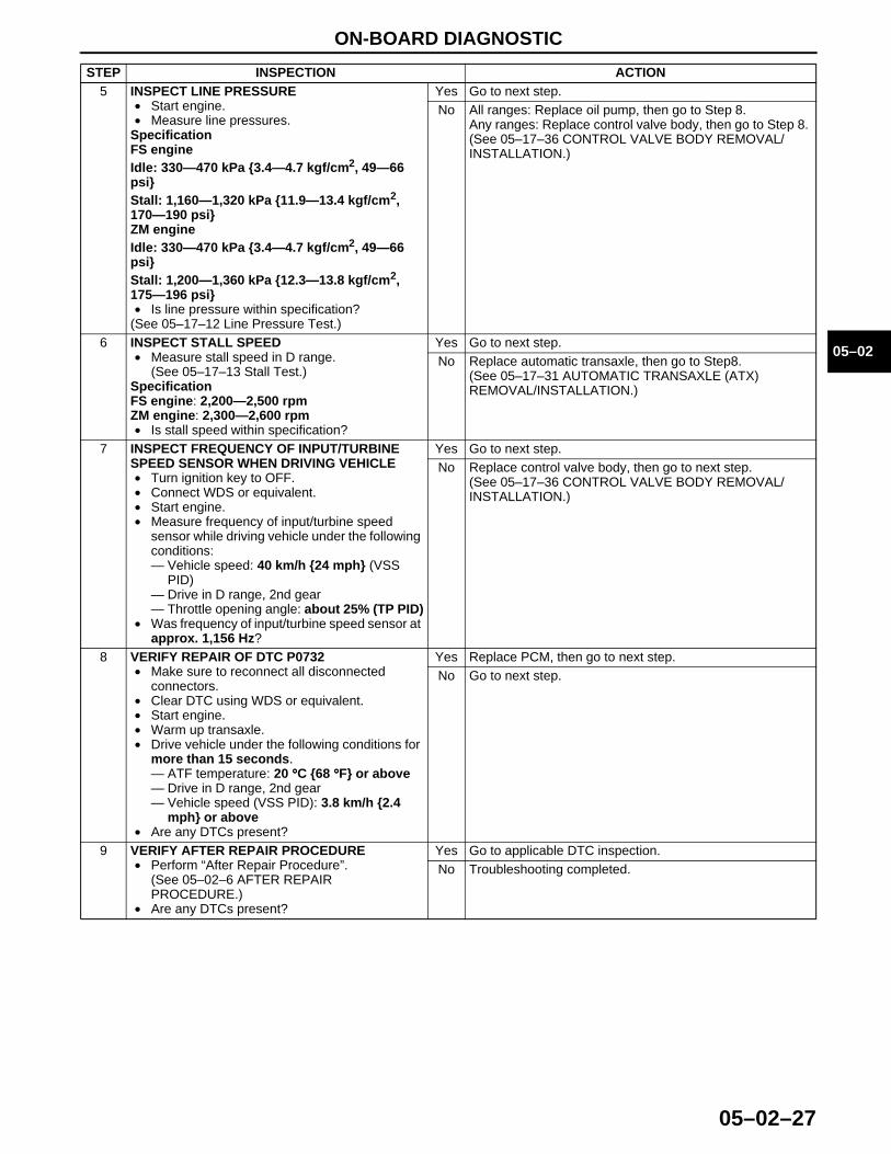
5 INSPECT LINE PRESSURE• Start engine.• Measure line pressures.
SpecificationFS engineIdle: 330—470 kPa {3.4—4.7 kgf/cm2, 49—66 psi}Stall: 1,160—1,320 kPa {11.9—13.4 kgf/cm2, 170—190 psi}ZM engineIdle: 330—470 kPa {3.4—4.7 kgf/cm2, 49—66 psi}Stall: 1,200—1,360 kPa {12.3—13.8 kgf/cm2, 175—196 psi}• Is line pressure within specification?
(See 05–17–12 Line Pressure Test.)
Yes Go to next step.No All ranges: Replace oil pump, then go to Step 8.
Any ranges: Replace control valve body, then go to Step 8. (See 05–17–36 CONTROL VALVE BODY REMOVAL/INSTALLATION.)
6 INSPECT STALL SPEED• Measure stall speed in D range.
(See 05–17–13 Stall Test.)SpecificationFS engine: 2,200—2,500 rpmZM engine: 2,300—2,600 rpm• Is stall speed within specification?
Yes Go to next step.No Replace automatic transaxle, then go to Step8.
(See 05–17–31 AUTOMATIC TRANSAXLE (ATX) REMOVAL/INSTALLATION.)
7 INSPECT FREQUENCY OF INPUT/TURBINE SPEED SENSOR WHEN DRIVING VEHICLE• Turn ignition key to OFF.• Connect WDS or equivalent.• Start engine.• Measure frequency of input/turbine speed
sensor while driving vehicle under the following conditions:— Vehicle speed: 40 km/h {24 mph} (VSS
PID)— Drive in D range, 2nd gear— Throttle opening angle: about 25% (TP PID)
• Was frequency of input/turbine speed sensor at approx. 1,156 Hz?
Yes Go to next step.No Replace control valve body, then go to next step.
(See 05–17–36 CONTROL VALVE BODY REMOVAL/INSTALLATION.)
8 VERIFY REPAIR OF DTC P0732• Make sure to reconnect all disconnected
connectors.• Clear DTC using WDS or equivalent.• Start engine.• Warm up transaxle.• Drive vehicle under the following conditions for
more than 15 seconds.— ATF temperature: 20 °°°°C {68 °°°°F} or above— Drive in D range, 2nd gear— Vehicle speed (VSS PID): 3.8 km/h {2.4
mph} or above• Are any DTCs present?
Yes Replace PCM, then go to next step.No Go to next step.
9 VERIFY AFTER REPAIR PROCEDURE• Perform “After Repair Procedure”.
(See 05–02–6 AFTER REPAIR PROCEDURE.)
• Are any DTCs present?
Yes Go to applicable DTC inspection.No Troubleshooting completed.
STEP INSPECTION ACTION
1712-1U-01G(05-02).fm 27 ページ 2001年6月29日 金曜日 午後4時35分
ON-BOARD DIAGNOSTIC
05–02–28
DTC P0733A3U050201030W14
Diagnostic procedure
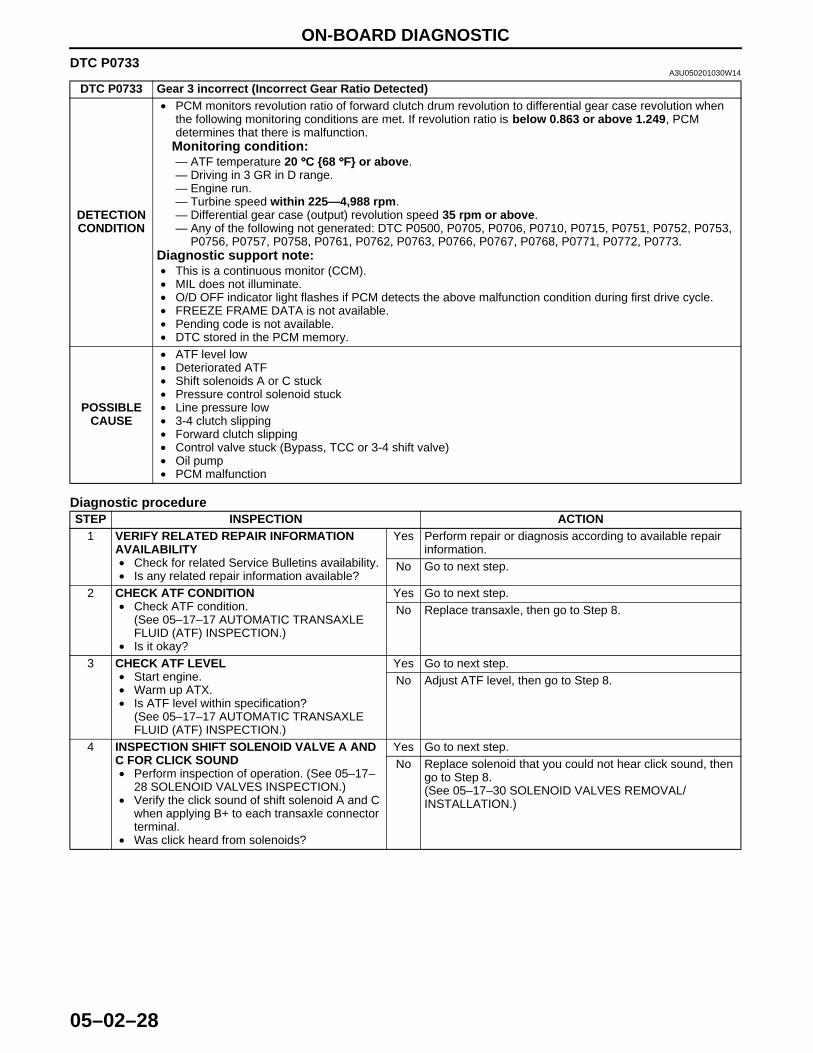
DTC P0733 Gear 3 incorrect (Incorrect Gear Ratio Detected)
DETECTION CONDITION
• PCM monitors revolution ratio of forward clutch drum revolution to differential gear case revolution when the following monitoring conditions are met. If revolution ratio is below 0.863 or above 1.249, PCM determines that there is malfunction.
Monitoring condition:— ATF temperature 20 °°°°C {68 °°°°F} or above.— Driving in 3 GR in D range.— Engine run.— Turbine speed within 225—4,988 rpm.— Differential gear case (output) revolution speed 35 rpm or above.— Any of the following not generated: DTC P0500, P0705, P0706, P0710, P0715, P0751, P0752, P0753,
P0756, P0757, P0758, P0761, P0762, P0763, P0766, P0767, P0768, P0771, P0772, P0773.Diagnostic support note:• This is a continuous monitor (CCM).• MIL does not illuminate.• O/D OFF indicator light flashes if PCM detects the above malfunction condition during first drive cycle.• FREEZE FRAME DATA is not available.• Pending code is not available.• DTC stored in the PCM memory.
POSSIBLE CAUSE
• ATF level low• Deteriorated ATF• Shift solenoids A or C stuck• Pressure control solenoid stuck• Line pressure low• 3-4 clutch slipping• Forward clutch slipping• Control valve stuck (Bypass, TCC or 3-4 shift valve)• Oil pump• PCM malfunction
STEP INSPECTION ACTION1 VERIFY RELATED REPAIR INFORMATION
AVAILABILITY• Check for related Service Bulletins availability.• Is any related repair information available?
Yes Perform repair or diagnosis according to available repair information.
No Go to next step.
2 CHECK ATF CONDITION• Check ATF condition.
(See 05–17–17 AUTOMATIC TRANSAXLE FLUID (ATF) INSPECTION.)
• Is it okay?
Yes Go to next step.No Replace transaxle, then go to Step 8.
3 CHECK ATF LEVEL• Start engine.• Warm up ATX.• Is ATF level within specification?
(See 05–17–17 AUTOMATIC TRANSAXLE FLUID (ATF) INSPECTION.)
Yes Go to next step.No Adjust ATF level, then go to Step 8.
4 INSPECTION SHIFT SOLENOID VALVE A AND C FOR CLICK SOUND• Perform inspection of operation. (See 05–17–
28 SOLENOID VALVES INSPECTION.)• Verify the click sound of shift solenoid A and C
when applying B+ to each transaxle connector terminal.
• Was click heard from solenoids?
Yes Go to next step.No Replace solenoid that you could not hear click sound, then
go to Step 8.(See 05–17–30 SOLENOID VALVES REMOVAL/INSTALLATION.)
1712-1U-01G(05-02).fm 28 ページ 2001年6月29日 金曜日 午後4時35分
ON-BOARD DIAGNOSTIC
05–02–29
05–02
End Of Sie
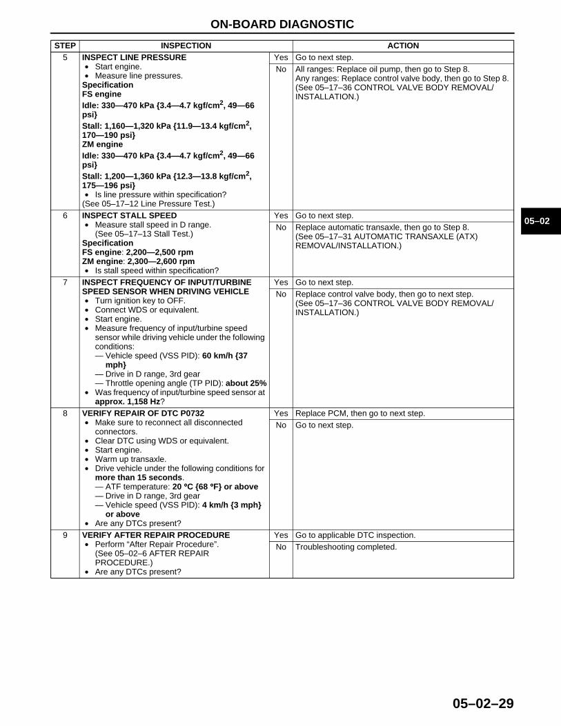
5 INSPECT LINE PRESSURE• Start engine.• Measure line pressures.
SpecificationFS engineIdle: 330—470 kPa {3.4—4.7 kgf/cm2, 49—66 psi}Stall: 1,160—1,320 kPa {11.9—13.4 kgf/cm2, 170—190 psi}ZM engineIdle: 330—470 kPa {3.4—4.7 kgf/cm2, 49—66 psi}Stall: 1,200—1,360 kPa {12.3—13.8 kgf/cm2, 175—196 psi}• Is line pressure within specification?
(See 05–17–12 Line Pressure Test.)
Yes Go to next step.No All ranges: Replace oil pump, then go to Step 8.
Any ranges: Replace control valve body, then go to Step 8. (See 05–17–36 CONTROL VALVE BODY REMOVAL/INSTALLATION.)
6 INSPECT STALL SPEED• Measure stall speed in D range.
(See 05–17–13 Stall Test.)SpecificationFS engine: 2,200—2,500 rpmZM engine: 2,300—2,600 rpm• Is stall speed within specification?
Yes Go to next step.No Replace automatic transaxle, then go to Step 8.
(See 05–17–31 AUTOMATIC TRANSAXLE (ATX) REMOVAL/INSTALLATION.)
7 INSPECT FREQUENCY OF INPUT/TURBINE SPEED SENSOR WHEN DRIVING VEHICLE• Turn ignition key to OFF.• Connect WDS or equivalent.• Start engine.• Measure frequency of input/turbine speed
sensor while driving vehicle under the following conditions:— Vehicle speed (VSS PID): 60 km/h {37
mph}— Drive in D range, 3rd gear— Throttle opening angle (TP PID): about 25%
• Was frequency of input/turbine speed sensor at approx. 1,158 Hz?
Yes Go to next step.No Replace control valve body, then go to next step.
(See 05–17–36 CONTROL VALVE BODY REMOVAL/INSTALLATION.)
8 VERIFY REPAIR OF DTC P0732• Make sure to reconnect all disconnected
connectors.• Clear DTC using WDS or equivalent.• Start engine.• Warm up transaxle.• Drive vehicle under the following conditions for
more than 15 seconds.— ATF temperature: 20 °°°°C {68 °°°°F} or above— Drive in D range, 3rd gear— Vehicle speed (VSS PID): 4 km/h {3 mph}
or above• Are any DTCs present?
Yes Replace PCM, then go to next step.No Go to next step.
9 VERIFY AFTER REPAIR PROCEDURE• Perform “After Repair Procedure”.
(See 05–02–6 AFTER REPAIR PROCEDURE.)
• Are any DTCs present?
Yes Go to applicable DTC inspection.No Troubleshooting completed.
STEP INSPECTION ACTION
1712-1U-01G(05-02).fm 29 ページ 2001年6月29日 金曜日 午後4時35分
ON-BOARD DIAGNOSTIC
05–02–30
DTC P0734A3U050201030W15
Diagnostic procedure
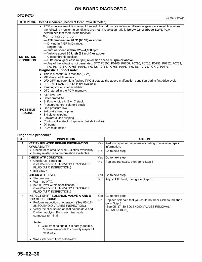
DTC P0734 Gear 4 incorrect (Incorrect Gear Ratio Detected)
DETECTION CONDITION
• PCM monitors revolution ratio of forward clutch drum revolution to differential gear case revolution when the following monitoring conditions are met. If revolution ratio is below 0.6 or above 1.249, PCM determines that there is malfunction.
Monitoring condition:— ATF temperature 20 °°°°C {68 °°°°F} or above.— Driving in 4 GR in D range.— Engine run.— Turbine speed within 225—4,988 rpm.— Vehicle speed 50 km/h {31 mph} or above.— Closed throttle position.— Differential gear case (output) revolution speed 35 rpm or above.— Any of the following not generated: DTC P0500, P0705, P0706, P0710, P0715, P0751, P0752, P0753,
P0756, P0757, P0758, P0761, P0762, P0763, P0766, P0767, P0768, P0771, P0772, P0773.Diagnostic support note:• This is a continuous monitor (CCM).• MIL does not illuminate.• O/D OFF indicator light flashes if PCM detects the above malfunction condition during first drive cycle.• FREEZE FRAME DATA is not available.• Pending code is not available.• DTC stored in the PCM memory.
POSSIBLE CAUSE
• ATF level low• Deteriorated ATF• Shift solenoids A, B or C stuck• Pressure control solenoid stuck• Line pressure low• 2-4 brake band slipping• 3-4 clutch slipping• Forward clutch slipping• Control valve stuck (Bypass or 3-4 shift valve)• Oil pump• PCM malfunction
STEP INSPECTION ACTION1 VERIFY RELATED REPAIR INFORMATION
AVAILABILITY• Check for related Service Bulletins availability.• Is any related repair information available?
Yes Perform repair or diagnosis according to available repair information.
No Go to next step.
2 CHECK ATF CONDITION• Check ATF condition.
(See 05–17–17 AUTOMATIC TRANSAXLE FLUID (ATF) INSPECTION.)
• Is it okay?
Yes Go to next step.No Replace transaxle, then go to Step 8.
3 CHECK ATF LEVEL• Start engine.• Warm up ATX.• Is ATF level within specification?
(See 05–17–17 AUTOMATIC TRANSAXLE FLUID (ATF) INSPECTION.)
Yes Go to next step.No Adjust ATF level, then go to Step 8.
4 INSPECT SHIFT SOLENOID VALVE A AND D FOR CLICK SOUND • Perform inspection of operation. (See 05–17–
28 SOLENOID VALVES INSPECTION.)• Verify the click sound of shift solenoids A and
D when applying B+ to each transaxle connector terminal.
Note• Click from solenoid D is barely audible.
Remove solenoids to correctly inspect if necessary.
• Was click heard from solenoids?
Yes Go to next step.No Replace solenoid that you could not hear click sound, then
go to Step 8.(See 05–17–30 SOLENOID VALVES REMOVAL/INSTALLATION.)
1712-1U-01G(05-02).fm 30 ページ 2001年6月29日 金曜日 午後4時35分

ON-BOARD DIAGNOSTIC
05–02–31
05–02
End Of Sie
5 INSPECT LINE PRESSURE• Start engine.• Measure line pressures.
SpecificationFS engineIdle: 330—470 kPa {3.4—4.7 kgf/cm2, 49—66 psi}Stall: 1,160—1,320 kPa {11.9—13.4 kgf/cm2, 170—190 psi}ZM engineIdle: 330—470 kPa {3.4—4.7 kgf/cm2, 49—66 psi}Stall: 1,200—1,360 kPa {12.3—13.8 kgf/cm2, 175—196 psi}• Is line pressure within specification?
(See 05–17–12 Line Pressure Test.)
Yes Go to next step.No All ranges: Replace oil pump, then go to Step 8.
Any ranges: Replace control valve body, then go to Step 8. (See 05–17–36 CONTROL VALVE BODY REMOVAL/INSTALLATION.)
6 INSPECT STALL SPEED• Measure stall speed in D range.
(See 05–17–13 Stall Test.)SpecificationFS engine: 2,200—2,500 rpmZM engine: 2,300—2,600 rpm• Is stall speed within specification?
Yes Go to next step.No Replace automatic transaxle, then go to Step 8.
(See 05–17–31 AUTOMATIC TRANSAXLE (ATX) REMOVAL/INSTALLATION.)
7 INSPECT FREQUENCY OF INPUT/TURBINE SPEED SENSOR WHEN DRIVING VEHICLE• Turn ignition key to OFF.• Connect WDS or equivalent.• Start engine.• Measure frequency of input/turbine speed
sensor while driving vehicle under the following conditions:— Vehicle speed (VSS PID): 80 km/h {49
mph}— Drive in D range, 4th gear— Throttle opening angle (TP PID): about 25%
• Was frequency of input/turbine speed sensor at approx. 1,120 Hz?
Yes Go to next step.No Replace control valve body, then go to next step.
(See 05–17–36 CONTROL VALVE BODY REMOVAL/INSTALLATION.)
8 VERIFY REPAIR OF DTC P0732• Make sure to reconnect all disconnected
connectors.• Clear DTC using WDS or equivalent.• Start engine.• Warm up transaxle.• Drive vehicle under the following conditions for
more than 15 seconds.— ATF temperature: 20 °°°°C {68 °°°°F} or above— Drive in D range, 4th gear— Throttle opening angle (TP PID): 0%— Vehicle speed (VSS PID): 50 km/h {31
mph} or above• Are any DTCs present?
Yes Replace PCM, then go to next step.No Go to next step.
9 VERIFY AFTER REPAIR PROCEDURE• Are any DTCs present?• Perform “After Repair Procedure”.
(See 05–02–6 AFTER REPAIR PROCEDURE.)
Yes Go to applicable DTC inspection.No Troubleshooting completed.
STEP INSPECTION ACTION
1712-1U-01G(05-02).fm 31 ページ 2001年6月29日 金曜日 午後4時35分
ON-BOARD DIAGNOSTIC
05–02–32
DTC P0741A3U050201030W16
Diagnostic procedure
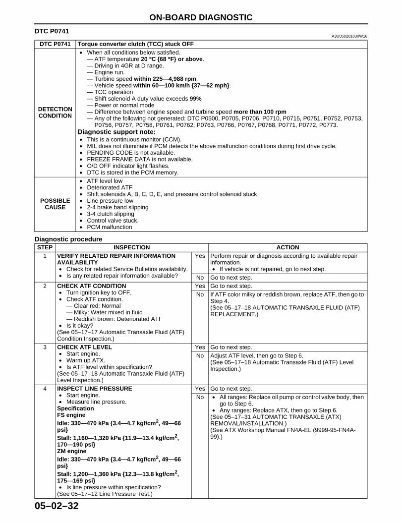
DTC P0741 Torque converter clutch (TCC) stuck OFF
DETECTION CONDITION
• When all conditions below satisfied.— ATF temperature 20 °°°°C {68 °°°°F} or above.— Driving in 4GR at D range.— Engine run.— Turbine speed within 225—4,988 rpm.— Vehicle speed within 60—100 km/h {37—62 mph}.— TCC operation— Shift solenoid A duty value exceeds 99%— Power or normal mode— Difference between engine speed and turbine speed more than 100 rpm— Any of the following not generated: DTC P0500, P0705, P0706, P0710, P0715, P0751, P0752, P0753,
P0756, P0757, P0758, P0761, P0762, P0763, P0766, P0767, P0768, P0771, P0772, P0773.Diagnostic support note:• This is a continuous monitor (CCM).• MIL does not illuminate if PCM detects the above malfunction conditions during first drive cycle.• PENDING CODE is not available.• FREEZE FRAME DATA is not available.• O/D OFF indicator light flashes.• DTC is stored in the PCM memory.
POSSIBLE CAUSE
• ATF level low• Deteriorated ATF• Shift solenoids A, B, C, D, E, and pressure control solenoid stuck• Line pressure low• 2-4 brake band slipping• 3-4 clutch slipping• Control valve stuck.• PCM malfunction
STEP INSPECTION ACTION1 VERIFY RELATED REPAIR INFORMATION
AVAILABILITY• Check for related Service Bulletins availability.• Is any related repair information available?
Yes Perform repair or diagnosis according to available repair information.• If vehicle is not repaired, go to next step.
No Go to next step.2 CHECK ATF CONDITION
• Turn ignition key to OFF.• Check ATF condition.
— Clear red: Normal— Milky: Water mixed in fluid— Reddish brown: Deteriorated ATF
• Is it okay?(See 05–17–17 Automatic Transaxle Fluid (ATF) Condition Inspection.)
Yes Go to next step.No If ATF color milky or reddish brown, replace ATF, then go to
Step 4.(See 05–17–18 AUTOMATIC TRANSAXLE FLUID (ATF) REPLACEMENT.)
3 CHECK ATF LEVEL• Start engine.• Warm up ATX.• Is ATF level within specification?
(See 05–17–18 Automatic Transaxle Fluid (ATF) Level Inspection.)
Yes Go to next step.No Adjust ATF level, then go to Step 6.
(See 05–17–18 Automatic Transaxle Fluid (ATF) Level Inspection.)
4 INSPECT LINE PRESSURE• Start engine.• Measure line pressure.
SpecificationFS engineIdle: 330—470 kPa {3.4—4.7 kgf/cm2, 49—66 psi}Stall: 1,160—1,320 kPa {11.9—13.4 kgf/cm2, 170—190 psi}ZM engineIdle: 330—470 kPa {3.4—4.7 kgf/cm2, 49—66 psi}Stall: 1,200—1,360 kPa {12.3—13.8 kgf/cm2, 175—169 psi}• Is line pressure within specification?
(See 05–17–12 Line Pressure Test.)
Yes Go to next step.No • All ranges: Replace oil pump or control valve body, then
go to Step 6.• Any ranges: Replace ATX, then go to Step 6.
(See 05–17–31 AUTOMATIC TRANSAXLE (ATX) REMOVAL/INSTALLATION.)(See ATX Workshop Manual FN4A-EL (9999-95-FN4A-99).)
1712-1U-01G(05-02).fm 32 ページ 2001年6月29日 金曜日 午後4時35分
ON-BOARD DIAGNOSTIC
05–02–33
05–02
End Of SieDTC P0742
A3U050201030W17
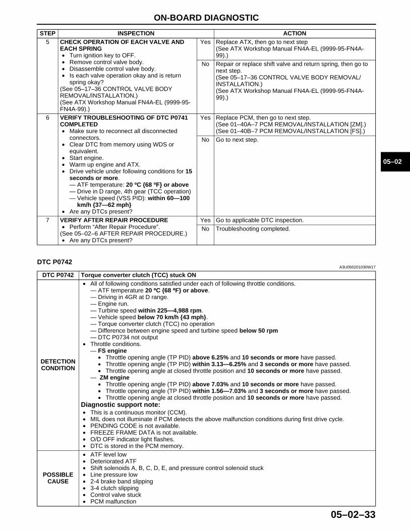
5 CHECK OPERATION OF EACH VALVE AND EACH SPRING• Turn ignition key to OFF.• Remove control valve body.• Disassemble control valve body.• Is each valve operation okay and is return
spring okay?(See 05–17–36 CONTROL VALVE BODY REMOVAL/INSTALLATION.)(See ATX Workshop Manual FN4A-EL (9999-95-FN4A-99).)
Yes Replace ATX, then go to next step(See ATX Workshop Manual FN4A-EL (9999-95-FN4A-99).)
No Repair or replace shift valve and return spring, then go to next step.(See 05–17–36 CONTROL VALVE BODY REMOVAL/INSTALLATION.)(See ATX Workshop Manual FN4A-EL (9999-95-FN4A-99).)
6 VERIFY TROUBLESHOOTING OF DTC P0741 COMPLETED• Make sure to reconnect all disconnected
connectors.• Clear DTC from memory using WDS or
equivalent.• Start engine.• Warm up engine and ATX.• Drive vehicle under following conditions for 15
seconds or more.— ATF temperature: 20 °°°°C {68 °°°°F} or above— Drive in D range, 4th gear (TCC operation)— Vehicle speed (VSS PID): within 60—100
km/h {37—62 mph}• Are any DTCs present?
Yes Replace PCM, then go to next step.(See 01–40A–7 PCM REMOVAL/INSTALLATION [ZM].)(See 01–40B–7 PCM REMOVAL/INSTALLATION [FS].)
No Go to next step.
7 VERIFY AFTER REPAIR PROCEDURE• Perform “After Repair Procedure”.
(See 05–02–6 AFTER REPAIR PROCEDURE.)• Are any DTCs present?
Yes Go to applicable DTC inspection.No Troubleshooting completed.
STEP INSPECTION ACTION
DTC P0742 Torque converter clutch (TCC) stuck ON
DETECTION CONDITION
• All of following conditions satisfied under each of following throttle conditions.— ATF temperature 20 °°°°C {68 °°°°F} or above.— Driving in 4GR at D range.— Engine run.— Turbine speed within 225—4,988 rpm.— Vehicle speed below 70 km/h {43 mph}.— Torque converter clutch (TCC) no operation— Difference between engine speed and turbine speed below 50 rpm— DTC P0734 not output
• Throttle conditions.— FS engine
• Throttle opening angle (TP PID) above 6.25% and 10 seconds or more have passed.• Throttle opening angle (TP PID) within 3.13—6.25% and 3 seconds or more have passed.• Throttle opening angle at closed throttle position and 10 seconds or more have passed.
— ZM engine• Throttle opening angle (TP PID) above 7.03% and 10 seconds or more have passed.• Throttle opening angle (TP PID) within 1.56—7.03% and 3 seconds or more have passed.• Throttle opening angle at closed throttle position and 10 seconds or more have passed.
Diagnostic support note:• This is a continuous monitor (CCM).• MIL does not illuminate if PCM detects the above malfunction conditions during first drive cycle.• PENDING CODE is not available.• FREEZE FRAME DATA is not available.• O/D OFF indicator light flashes.• DTC is stored in the PCM memory.
POSSIBLE CAUSE
• ATF level low• Deteriorated ATF• Shift solenoids A, B, C, D, E, and pressure control solenoid stuck• Line pressure low• 2-4 brake band slipping• 3-4 clutch slipping• Control valve stuck• PCM malfunction
1712-1U-01G(05-02).fm 33 ページ 2001年6月29日 金曜日 午後4時35分
ON-BOARD DIAGNOSTIC
05–02–34
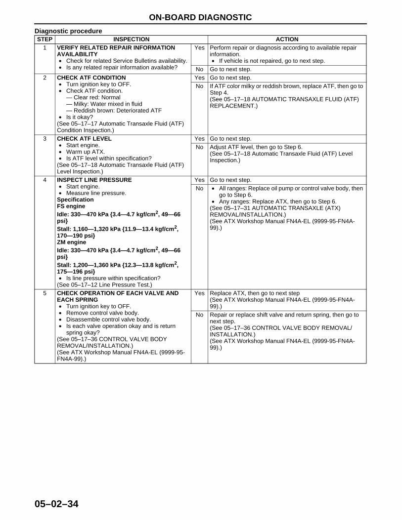
Diagnostic procedureSTEP INSPECTION ACTION
1 VERIFY RELATED REPAIR INFORMATION AVAILABILITY• Check for related Service Bulletins availability.• Is any related repair information available?
Yes Perform repair or diagnosis according to available repair information.• If vehicle is not repaired, go to next step.
No Go to next step.2 CHECK ATF CONDITION
• Turn ignition key to OFF.• Check ATF condition.
— Clear red: Normal— Milky: Water mixed in fluid— Reddish brown: Deteriorated ATF
• Is it okay?(See 05–17–17 Automatic Transaxle Fluid (ATF) Condition Inspection.)
Yes Go to next step.No If ATF color milky or reddish brown, replace ATF, then go to
Step 4.(See 05–17–18 AUTOMATIC TRANSAXLE FLUID (ATF) REPLACEMENT.)
3 CHECK ATF LEVEL• Start engine.• Warm up ATX.• Is ATF level within specification?
(See 05–17–18 Automatic Transaxle Fluid (ATF) Level Inspection.)
Yes Go to next step.No Adjust ATF level, then go to Step 6.
(See 05–17–18 Automatic Transaxle Fluid (ATF) Level Inspection.)
4 INSPECT LINE PRESSURE• Start engine.• Measure line pressure.
SpecificationFS engineIdle: 330—470 kPa {3.4—4.7 kgf/cm2, 49—66 psi}Stall: 1,160—1,320 kPa {11.9—13.4 kgf/cm2, 170—190 psi}ZM engineIdle: 330—470 kPa {3.4—4.7 kgf/cm2, 49—66 psi}Stall: 1,200—1,360 kPa {12.3—13.8 kgf/cm2, 175—196 psi}• Is line pressure within specification?
(See 05–17–12 Line Pressure Test.)
Yes Go to next step.No • All ranges: Replace oil pump or control valve body, then
go to Step 6.• Any ranges: Replace ATX, then go to Step 6.
(See 05–17–31 AUTOMATIC TRANSAXLE (ATX) REMOVAL/INSTALLATION.)(See ATX Workshop Manual FN4A-EL (9999-95-FN4A-99).)
5 CHECK OPERATION OF EACH VALVE AND EACH SPRING• Turn ignition key to OFF.• Remove control valve body.• Disassemble control valve body.• Is each valve operation okay and is return
spring okay?(See 05–17–36 CONTROL VALVE BODY REMOVAL/INSTALLATION.)(See ATX Workshop Manual FN4A-EL (9999-95-FN4A-99).)
Yes Replace ATX, then go to next step(See ATX Workshop Manual FN4A-EL (9999-95-FN4A-99).)
No Repair or replace shift valve and return spring, then go to next step.(See 05–17–36 CONTROL VALVE BODY REMOVAL/INSTALLATION.)(See ATX Workshop Manual FN4A-EL (9999-95-FN4A-99).)
1712-1U-01G(05-02).fm 34 ページ 2001年6月29日 金曜日 午後4時35分
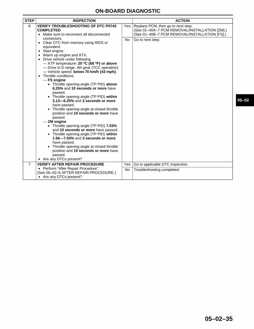
ON-BOARD DIAGNOSTIC
05–02–35
05–02
End Of Sie
6 VERIFY TROUBLESHOOTING OF DTC P0742 COMPLETED• Make sure to reconnect all disconnected
connectors.• Clear DTC from memory using WDS or
equivalent.• Start engine.• Warm up engine and ATX.• Drive vehicle under following.
— ATF temperature: 20 °°°°C {68 °°°°F} or above— Drive in D range, 4th gear (TCC operation)— Vehicle speed: below 70 km/h {43 mph}.
• Throttle conditions— FS engine
• Throttle opening angle (TP PID) above 6.25% and 10 seconds or more have passed.
• Throttle opening angle (TP PID) within 3.13—6.25% and 3 seconds or more have passed.
• Throttle opening angle at closed throttle position and 10 seconds or more have passed.
— ZM engine• Throttle opening angle (TP PID) 7.03%
and 10 seconds or more have passed.• Throttle opening angle (TP PID) within
1.56—7.03% and 3 seconds or more have passed.
• Throttle opening angle at closed throttle position and 10 seconds or more have passed.
• Are any DTCs present?
Yes Replace PCM, then go to next step.(See 01–40A–7 PCM REMOVAL/INSTALLATION [ZM].)(See 01–40B–7 PCM REMOVAL/INSTALLATION [FS].)
No Go to next step.
7 VERIFY AFTER REPAIR PROCEDURE• Perform “After Repair Procedure”.
(See 05–02–6 AFTER REPAIR PROCEDURE.)• Are any DTCs present?
Yes Go to applicable DTC inspection.No Troubleshooting completed.
STEP INSPECTION ACTION
1712-1U-01G(05-02).fm 35 ページ 2001年6月29日 金曜日 午後4時35分
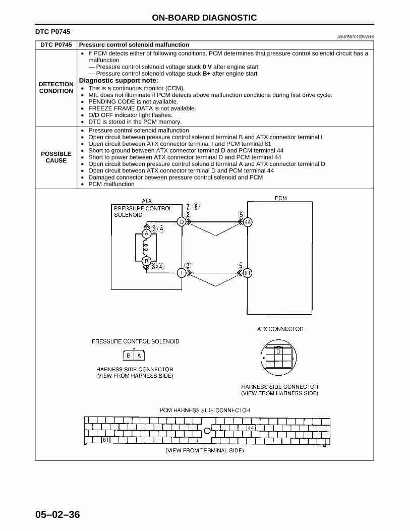
ON-BOARD DIAGNOSTIC
05–02–36
DTC P0745A3U050201030W18
DTC P0745 Pressure control solenoid malfunction
DETECTION CONDITION
• If PCM detects either of following conditions, PCM determines that pressure control solenoid circuit has a malfunction— Pressure control solenoid voltage stuck 0 V after engine start— Pressure control solenoid voltage stuck B+ after engine start
Diagnostic support note:• This is a continuous monitor (CCM).• MIL does not illuminate if PCM detects above malfunction conditions during first drive cycle.• PENDING CODE is not available.• FREEZE FRAME DATA is not available.• O/D OFF indicator light flashes.• DTC is stored in the PCM memory.
POSSIBLE CAUSE
• Pressure control solenoid malfunction• Open circuit between pressure control solenoid terminal B and ATX connector terminal I • Open circuit between ATX connector terminal I and PCM terminal 81• Short to ground between ATX connector terminal D and PCM terminal 44• Short to power between ATX connector terminal D and PCM terminal 44• Open circuit between pressure control solenoid terminal A and ATX connector terminal D• Open circuit between ATX connector terminal D and PCM terminal 44• Damaged connector between pressure control solenoid and PCM• PCM malfunction
1712-1U-01G(05-02).fm 36 ページ 2001年6月29日 金曜日 午後4時35分
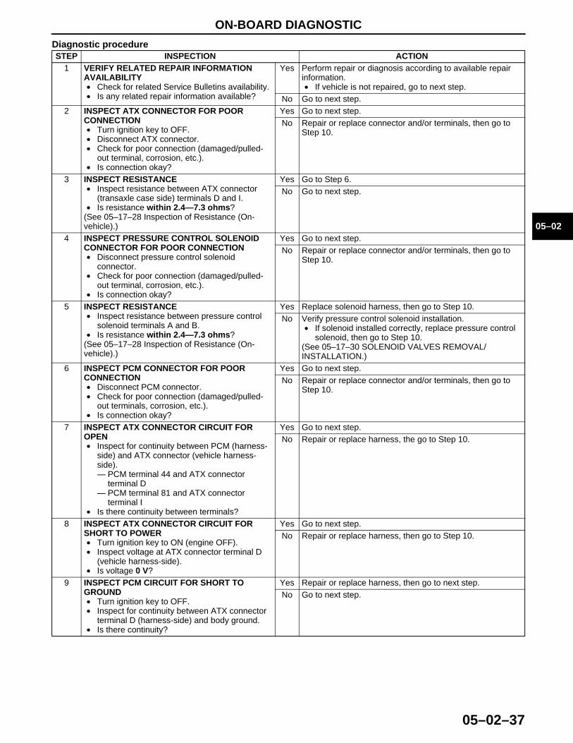
ON-BOARD DIAGNOSTIC
05–02–37
05–02
Diagnostic procedureSTEP INSPECTION ACTION
1 VERIFY RELATED REPAIR INFORMATION AVAILABILITY• Check for related Service Bulletins availability.• Is any related repair information available?
Yes Perform repair or diagnosis according to available repair information.• If vehicle is not repaired, go to next step.
No Go to next step.2 INSPECT ATX CONNECTOR FOR POOR
CONNECTION• Turn ignition key to OFF.• Disconnect ATX connector.• Check for poor connection (damaged/pulled-
out terminal, corrosion, etc.).• Is connection okay?
Yes Go to next step.No Repair or replace connector and/or terminals, then go to
Step 10.
3 INSPECT RESISTANCE• Inspect resistance between ATX connector
(transaxle case side) terminals D and I.• Is resistance within 2.4—7.3 ohms?
(See 05–17–28 Inspection of Resistance (On-vehicle).)
Yes Go to Step 6.No Go to next step.
4 INSPECT PRESSURE CONTROL SOLENOID CONNECTOR FOR POOR CONNECTION• Disconnect pressure control solenoid
connector.• Check for poor connection (damaged/pulled-
out terminal, corrosion, etc.).• Is connection okay?
Yes Go to next step.No Repair or replace connector and/or terminals, then go to
Step 10.
5 INSPECT RESISTANCE• Inspect resistance between pressure control
solenoid terminals A and B.• Is resistance within 2.4—7.3 ohms?
(See 05–17–28 Inspection of Resistance (On-vehicle).)
Yes Replace solenoid harness, then go to Step 10.No Verify pressure control solenoid installation.
• If solenoid installed correctly, replace pressure control solenoid, then go to Step 10.
(See 05–17–30 SOLENOID VALVES REMOVAL/INSTALLATION.)
6 INSPECT PCM CONNECTOR FOR POOR CONNECTION• Disconnect PCM connector.• Check for poor connection (damaged/pulled-
out terminals, corrosion, etc.).• Is connection okay?
Yes Go to next step.No Repair or replace connector and/or terminals, then go to
Step 10.
7 INSPECT ATX CONNECTOR CIRCUIT FOR OPEN• Inspect for continuity between PCM (harness-
side) and ATX connector (vehicle harness-side).— PCM terminal 44 and ATX connector
terminal D— PCM terminal 81 and ATX connector
terminal I• Is there continuity between terminals?
Yes Go to next step.No Repair or replace harness, the go to Step 10.
8 INSPECT ATX CONNECTOR CIRCUIT FOR SHORT TO POWER• Turn ignition key to ON (engine OFF).• Inspect voltage at ATX connector terminal D
(vehicle harness-side).• Is voltage 0 V?
Yes Go to next step.No Repair or replace harness, then go to Step 10.
9 INSPECT PCM CIRCUIT FOR SHORT TO GROUND• Turn ignition key to OFF.• Inspect for continuity between ATX connector
terminal D (harness-side) and body ground.• Is there continuity?
Yes Repair or replace harness, then go to next step.No Go to next step.
1712-1U-01G(05-02).fm 37 ページ 2001年6月29日 金曜日 午後4時35分
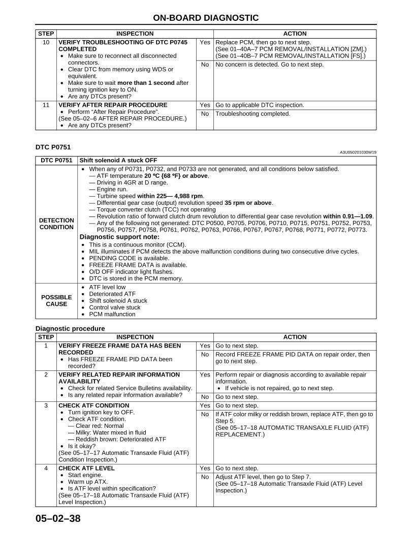
ON-BOARD DIAGNOSTIC
05–02–38
End Of SieDTC P0751
A3U050201030W19
Diagnostic procedure
10 VERIFY TROUBLESHOOTING OF DTC P0745 COMPLETED• Make sure to reconnect all disconnected
connectors.• Clear DTC from memory using WDS or
equivalent.• Make sure to wait more than 1 second after
turning ignition key to ON.• Are any DTCs present?
Yes Replace PCM, then go to next step.(See 01–40A–7 PCM REMOVAL/INSTALLATION [ZM].)(See 01–40B–7 PCM REMOVAL/INSTALLATION [FS].)
No No concern is detected. Go to next step.
11 VERIFY AFTER REPAIR PROCEDURE• Perform “After Repair Procedure”.
(See 05–02–6 AFTER REPAIR PROCEDURE.)• Are any DTCs present?
Yes Go to applicable DTC inspection.No Troubleshooting completed.
STEP INSPECTION ACTION
DTC P0751 Shift solenoid A stuck OFF
DETECTION CONDITION
• When any of P0731, P0732, and P0733 are not generated, and all conditions below satisfied.— ATF temperature 20 °°°°C {68 °°°°F} or above.— Driving in 4GR at D range.— Engine run.— Turbine speed within 225— 4,988 rpm.— Differential gear case (output) revolution speed 35 rpm or above.— Torque converter clutch (TCC) not operating— Revolution ratio of forward clutch drum revolution to differential gear case revolution within 0.91—1.09.— Any of the following not generated: DTC P0500, P0705, P0706, P0710, P0715, P0751, P0752, P0753,
P0756, P0757, P0758, P0761, P0762, P0763, P0766, P0767, P0767, P0768, P0771, P0772, P0773.Diagnostic support note:• This is a continuous monitor (CCM).• MIL illuminates if PCM detects the above malfunction conditions during two consecutive drive cycles.• PENDING CODE is available.• FREEZE FRAME DATA is available.• O/D OFF indicator light flashes.• DTC is stored in the PCM memory.
POSSIBLE CAUSE
• ATF level low• Deteriorated ATF• Shift solenoid A stuck• Control valve stuck• PCM malfunction
STEP INSPECTION ACTION1 VERIFY FREEZE FRAME DATA HAS BEEN
RECORDED• Has FREEZE FRAME PID DATA been
recorded?
Yes Go to next step.No Record FREEZE FRAME PID DATA on repair order, then
go to next step.
2 VERIFY RELATED REPAIR INFORMATION AVAILABILITY• Check for related Service Bulletins availability.• Is any related repair information available?
Yes Perform repair or diagnosis according to available repair information.• If vehicle is not repaired, go to next step.
No Go to next step.3 CHECK ATF CONDITION
• Turn ignition key to OFF.• Check ATF condition.
— Clear red: Normal— Milky: Water mixed in fluid— Reddish brown: Deteriorated ATF
• Is it okay?(See 05–17–17 Automatic Transaxle Fluid (ATF) Condition Inspection.)
Yes Go to next step.No If ATF color milky or reddish brown, replace ATF, then go to
Step 5.(See 05–17–18 AUTOMATIC TRANSAXLE FLUID (ATF) REPLACEMENT.)
4 CHECK ATF LEVEL• Start engine.• Warm up ATX.• Is ATF level within specification?
(See 05–17–18 Automatic Transaxle Fluid (ATF) Level Inspection.)
Yes Go to next step.No Adjust ATF level, then go to Step 7.
(See 05–17–18 Automatic Transaxle Fluid (ATF) Level Inspection.)
1712-1U-01G(05-02).fm 38 ページ 2001年6月29日 金曜日 午後4時35分
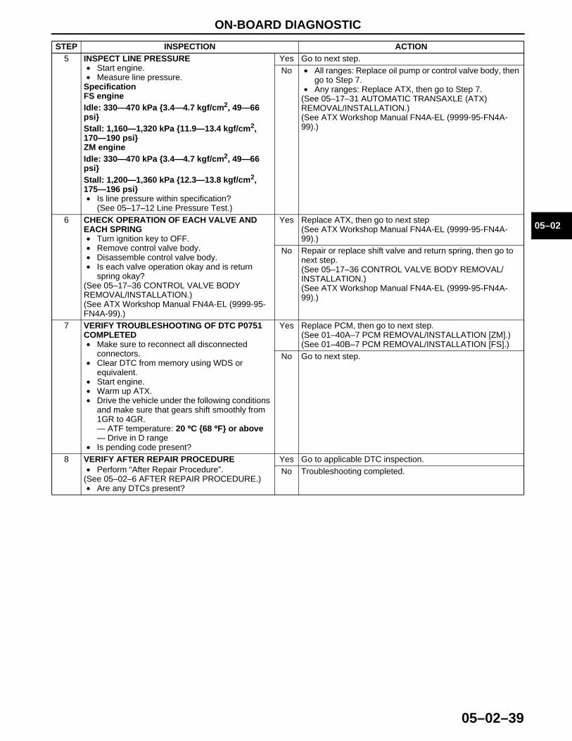
ON-BOARD DIAGNOSTIC
05–02–39
05–02
End Of Sie
5 INSPECT LINE PRESSURE• Start engine.• Measure line pressure.
SpecificationFS engineIdle: 330—470 kPa {3.4—4.7 kgf/cm2, 49—66 psi}Stall: 1,160—1,320 kPa {11.9—13.4 kgf/cm2, 170—190 psi}ZM engineIdle: 330—470 kPa {3.4—4.7 kgf/cm2, 49—66 psi}Stall: 1,200—1,360 kPa {12.3—13.8 kgf/cm2, 175—196 psi}• Is line pressure within specification?
(See 05–17–12 Line Pressure Test.)
Yes Go to next step.No • All ranges: Replace oil pump or control valve body, then
go to Step 7.• Any ranges: Replace ATX, then go to Step 7.
(See 05–17–31 AUTOMATIC TRANSAXLE (ATX) REMOVAL/INSTALLATION.)(See ATX Workshop Manual FN4A-EL (9999-95-FN4A-99).)
6 CHECK OPERATION OF EACH VALVE AND EACH SPRING• Turn ignition key to OFF.• Remove control valve body.• Disassemble control valve body.• Is each valve operation okay and is return
spring okay?(See 05–17–36 CONTROL VALVE BODY REMOVAL/INSTALLATION.)(See ATX Workshop Manual FN4A-EL (9999-95-FN4A-99).)
Yes Replace ATX, then go to next step(See ATX Workshop Manual FN4A-EL (9999-95-FN4A-99).)
No Repair or replace shift valve and return spring, then go to next step.(See 05–17–36 CONTROL VALVE BODY REMOVAL/INSTALLATION.)(See ATX Workshop Manual FN4A-EL (9999-95-FN4A-99).)
7 VERIFY TROUBLESHOOTING OF DTC P0751 COMPLETED• Make sure to reconnect all disconnected
connectors.• Clear DTC from memory using WDS or
equivalent.• Start engine.• Warm up ATX.• Drive the vehicle under the following conditions
and make sure that gears shift smoothly from 1GR to 4GR.— ATF temperature: 20 °°°°C {68 °°°°F} or above— Drive in D range
• Is pending code present?
Yes Replace PCM, then go to next step.(See 01–40A–7 PCM REMOVAL/INSTALLATION [ZM].)(See 01–40B–7 PCM REMOVAL/INSTALLATION [FS].)
No Go to next step.
8 VERIFY AFTER REPAIR PROCEDURE• Perform “After Repair Procedure”.
(See 05–02–6 AFTER REPAIR PROCEDURE.)• Are any DTCs present?
Yes Go to applicable DTC inspection.No Troubleshooting completed.
STEP INSPECTION ACTION
1712-1U-01G(05-02).fm 39 ページ 2001年6月29日 金曜日 午後4時35分
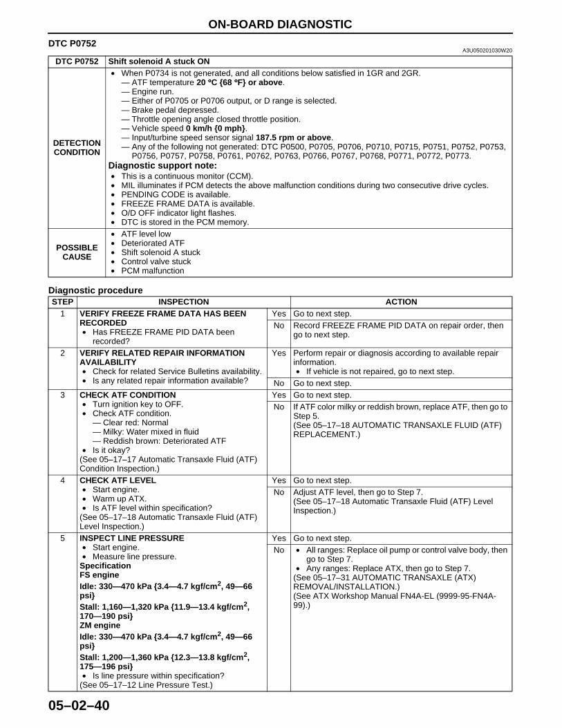
ON-BOARD DIAGNOSTIC
05–02–40
DTC P0752A3U050201030W20
Diagnostic procedure
DTC P0752 Shift solenoid A stuck ON
DETECTION CONDITION
• When P0734 is not generated, and all conditions below satisfied in 1GR and 2GR.— ATF temperature 20 °°°°C {68 °°°°F} or above.— Engine run.— Either of P0705 or P0706 output, or D range is selected.— Brake pedal depressed.— Throttle opening angle closed throttle position.— Vehicle speed 0 km/h {0 mph}.— Input/turbine speed sensor signal 187.5 rpm or above.— Any of the following not generated: DTC P0500, P0705, P0706, P0710, P0715, P0751, P0752, P0753,
P0756, P0757, P0758, P0761, P0762, P0763, P0766, P0767, P0768, P0771, P0772, P0773.Diagnostic support note:• This is a continuous monitor (CCM).• MIL illuminates if PCM detects the above malfunction conditions during two consecutive drive cycles.• PENDING CODE is available.• FREEZE FRAME DATA is available.• O/D OFF indicator light flashes.• DTC is stored in the PCM memory.
POSSIBLE CAUSE
• ATF level low• Deteriorated ATF• Shift solenoid A stuck• Control valve stuck• PCM malfunction
STEP INSPECTION ACTION1 VERIFY FREEZE FRAME DATA HAS BEEN
RECORDED• Has FREEZE FRAME PID DATA been
recorded?
Yes Go to next step.No Record FREEZE FRAME PID DATA on repair order, then
go to next step.
2 VERIFY RELATED REPAIR INFORMATION AVAILABILITY• Check for related Service Bulletins availability.• Is any related repair information available?
Yes Perform repair or diagnosis according to available repair information.• If vehicle is not repaired, go to next step.
No Go to next step.3 CHECK ATF CONDITION
• Turn ignition key to OFF.• Check ATF condition.
— Clear red: Normal— Milky: Water mixed in fluid— Reddish brown: Deteriorated ATF
• Is it okay?(See 05–17–17 Automatic Transaxle Fluid (ATF) Condition Inspection.)
Yes Go to next step.No If ATF color milky or reddish brown, replace ATF, then go to
Step 5.(See 05–17–18 AUTOMATIC TRANSAXLE FLUID (ATF) REPLACEMENT.)
4 CHECK ATF LEVEL• Start engine.• Warm up ATX.• Is ATF level within specification?
(See 05–17–18 Automatic Transaxle Fluid (ATF) Level Inspection.)
Yes Go to next step.No Adjust ATF level, then go to Step 7.
(See 05–17–18 Automatic Transaxle Fluid (ATF) Level Inspection.)
5 INSPECT LINE PRESSURE• Start engine.• Measure line pressure.
SpecificationFS engineIdle: 330—470 kPa {3.4—4.7 kgf/cm2, 49—66 psi}Stall: 1,160—1,320 kPa {11.9—13.4 kgf/cm2, 170—190 psi}ZM engineIdle: 330—470 kPa {3.4—4.7 kgf/cm2, 49—66 psi}Stall: 1,200—1,360 kPa {12.3—13.8 kgf/cm2, 175—196 psi}• Is line pressure within specification?
(See 05–17–12 Line Pressure Test.)
Yes Go to next step.No • All ranges: Replace oil pump or control valve body, then
go to Step 7.• Any ranges: Replace ATX, then go to Step 7.
(See 05–17–31 AUTOMATIC TRANSAXLE (ATX) REMOVAL/INSTALLATION.)(See ATX Workshop Manual FN4A-EL (9999-95-FN4A-99).)
1712-1U-01G(05-02).fm 40 ページ 2001年6月29日 金曜日 午後4時35分

ON-BOARD DIAGNOSTIC
05–02–41
05–02
End Of Sie
6 CHECK OPERATION OF EACH VALVE AND EACH SPRING• Turn ignition key to OFF.• Remove control valve body.• Disassemble control valve body.• Is each valve operation okay and is return
spring okay?(See 05–17–36 CONTROL VALVE BODY REMOVAL/INSTALLATION.)(See ATX Workshop Manual FN4A-EL (9999-95-FN4A-99).)
Yes Replace ATX, then go to next step(See ATX Workshop Manual FN4A-EL (9999-95-FN4A-99).)
No Repair or replace shift valve and return spring, then go to next step.(See 05–17–36 CONTROL VALVE BODY REMOVAL/INSTALLATION.)(See ATX Workshop Manual FN4A-EL (9999-95-FN4A-99).)
7 VERIFY TROUBLESHOOTING OF DTC P0752 COMPLETED• Make sure to reconnect all disconnected
connectors.• Clear DTC from memory using WDS or
equivalent.• Start engine.• Warm up ATX.• Drive the vehicle under the following conditions
and make sure that gears shift smoothly from 1GR to 4GR.— ATF temperature: 20 °°°°C {68 °°°°F} or above— Drive in D range
• Is pending code present?
Yes Replace PCM, then go to next step.(See 01–40A–7 PCM REMOVAL/INSTALLATION [ZM].)(See 01–40B–7 PCM REMOVAL/INSTALLATION [FS].)
No Go to next step.
8 VERIFY AFTER REPAIR PROCEDURE• Perform “After Repair Procedure”.
(See 05–02–6 AFTER REPAIR PROCEDURE.)• Are any DTCs present?
Yes Go to applicable DTC inspection.No Troubleshooting completed.
STEP INSPECTION ACTION
1712-1U-01G(05-02).fm 41 ページ 2001年6月29日 金曜日 午後4時35分
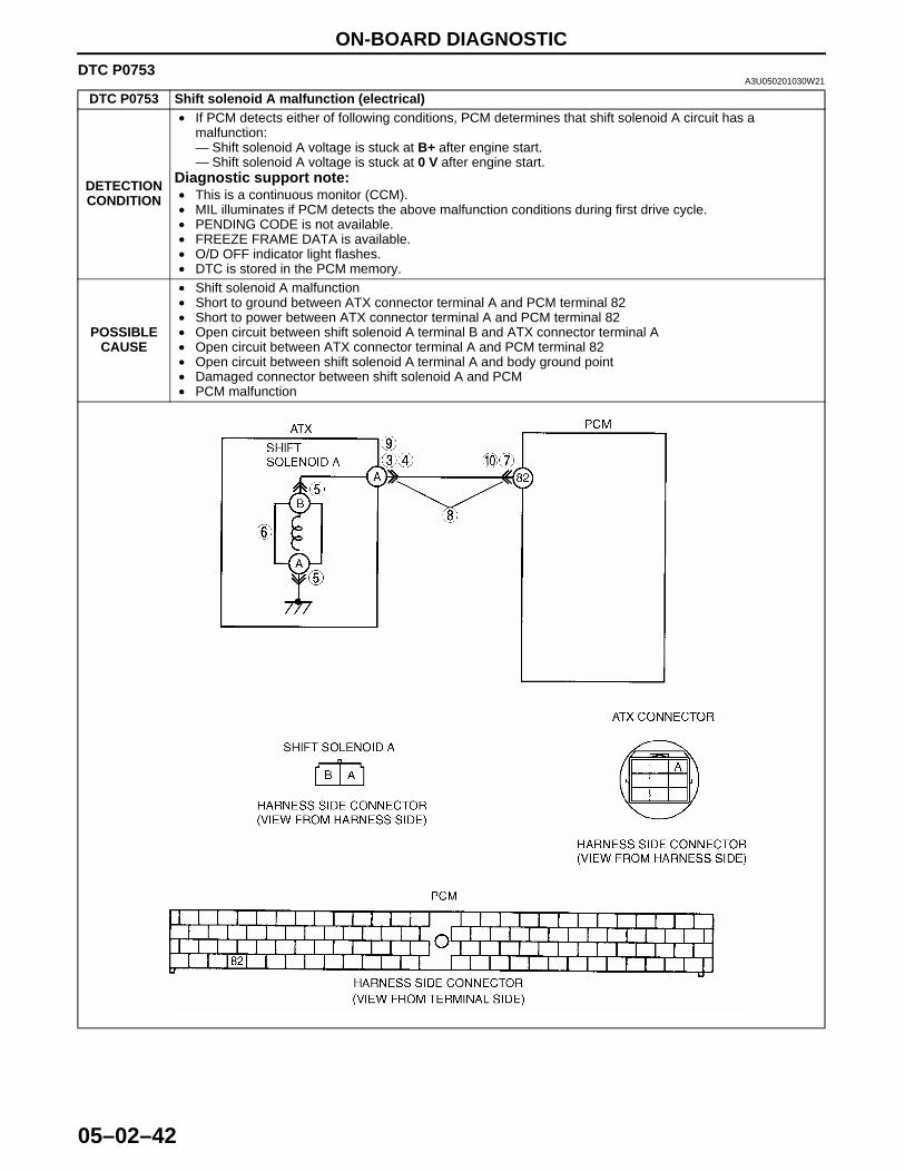
ON-BOARD DIAGNOSTIC
05–02–42
DTC P0753A3U050201030W21
DTC P0753 Shift solenoid A malfunction (electrical)
DETECTION CONDITION
• If PCM detects either of following conditions, PCM determines that shift solenoid A circuit has a malfunction:— Shift solenoid A voltage is stuck at B+ after engine start.— Shift solenoid A voltage is stuck at 0 V after engine start.
Diagnostic support note:• This is a continuous monitor (CCM).• MIL illuminates if PCM detects the above malfunction conditions during first drive cycle.• PENDING CODE is not available.• FREEZE FRAME DATA is available.• O/D OFF indicator light flashes.• DTC is stored in the PCM memory.
POSSIBLE CAUSE
• Shift solenoid A malfunction• Short to ground between ATX connector terminal A and PCM terminal 82• Short to power between ATX connector terminal A and PCM terminal 82• Open circuit between shift solenoid A terminal B and ATX connector terminal A • Open circuit between ATX connector terminal A and PCM terminal 82• Open circuit between shift solenoid A terminal A and body ground point• Damaged connector between shift solenoid A and PCM• PCM malfunction
1712-1U-01G(05-02).fm 42 ページ 2001年6月29日 金曜日 午後4時35分
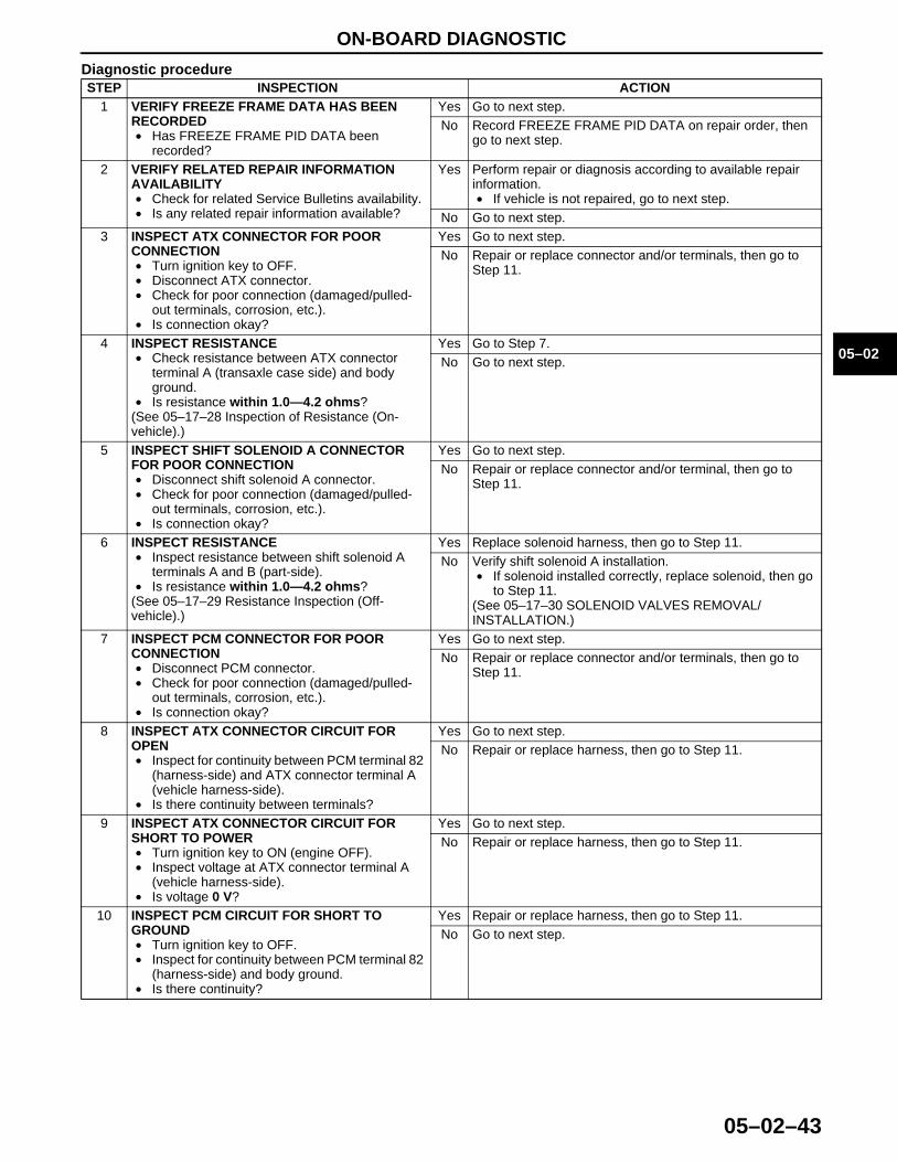
ON-BOARD DIAGNOSTIC
05–02–43
05–02
Diagnostic procedureSTEP INSPECTION ACTION
1 VERIFY FREEZE FRAME DATA HAS BEEN RECORDED• Has FREEZE FRAME PID DATA been
recorded?
Yes Go to next step.No Record FREEZE FRAME PID DATA on repair order, then
go to next step.
2 VERIFY RELATED REPAIR INFORMATION AVAILABILITY• Check for related Service Bulletins availability.• Is any related repair information available?
Yes Perform repair or diagnosis according to available repair information.• If vehicle is not repaired, go to next step.
No Go to next step.3 INSPECT ATX CONNECTOR FOR POOR
CONNECTION• Turn ignition key to OFF.• Disconnect ATX connector.• Check for poor connection (damaged/pulled-
out terminals, corrosion, etc.).• Is connection okay?
Yes Go to next step.No Repair or replace connector and/or terminals, then go to
Step 11.
4 INSPECT RESISTANCE• Check resistance between ATX connector
terminal A (transaxle case side) and body ground.
• Is resistance within 1.0—4.2 ohms?(See 05–17–28 Inspection of Resistance (On-vehicle).)
Yes Go to Step 7.No Go to next step.
5 INSPECT SHIFT SOLENOID A CONNECTOR FOR POOR CONNECTION• Disconnect shift solenoid A connector.• Check for poor connection (damaged/pulled-
out terminals, corrosion, etc.).• Is connection okay?
Yes Go to next step.No Repair or replace connector and/or terminal, then go to
Step 11.
6 INSPECT RESISTANCE• Inspect resistance between shift solenoid A
terminals A and B (part-side).• Is resistance within 1.0—4.2 ohms?
(See 05–17–29 Resistance Inspection (Off-vehicle).)
Yes Replace solenoid harness, then go to Step 11.No Verify shift solenoid A installation.
• If solenoid installed correctly, replace solenoid, then go to Step 11.
(See 05–17–30 SOLENOID VALVES REMOVAL/INSTALLATION.)
7 INSPECT PCM CONNECTOR FOR POOR CONNECTION• Disconnect PCM connector.• Check for poor connection (damaged/pulled-
out terminals, corrosion, etc.).• Is connection okay?
Yes Go to next step.No Repair or replace connector and/or terminals, then go to
Step 11.
8 INSPECT ATX CONNECTOR CIRCUIT FOR OPEN• Inspect for continuity between PCM terminal 82
(harness-side) and ATX connector terminal A (vehicle harness-side).
• Is there continuity between terminals?
Yes Go to next step.No Repair or replace harness, then go to Step 11.
9 INSPECT ATX CONNECTOR CIRCUIT FOR SHORT TO POWER• Turn ignition key to ON (engine OFF).• Inspect voltage at ATX connector terminal A
(vehicle harness-side).• Is voltage 0 V?
Yes Go to next step.No Repair or replace harness, then go to Step 11.
10 INSPECT PCM CIRCUIT FOR SHORT TO GROUND• Turn ignition key to OFF.• Inspect for continuity between PCM terminal 82
(harness-side) and body ground.• Is there continuity?
Yes Repair or replace harness, then go to Step 11.No Go to next step.
1712-1U-01G(05-02).fm 43 ページ 2001年6月29日 金曜日 午後4時35分
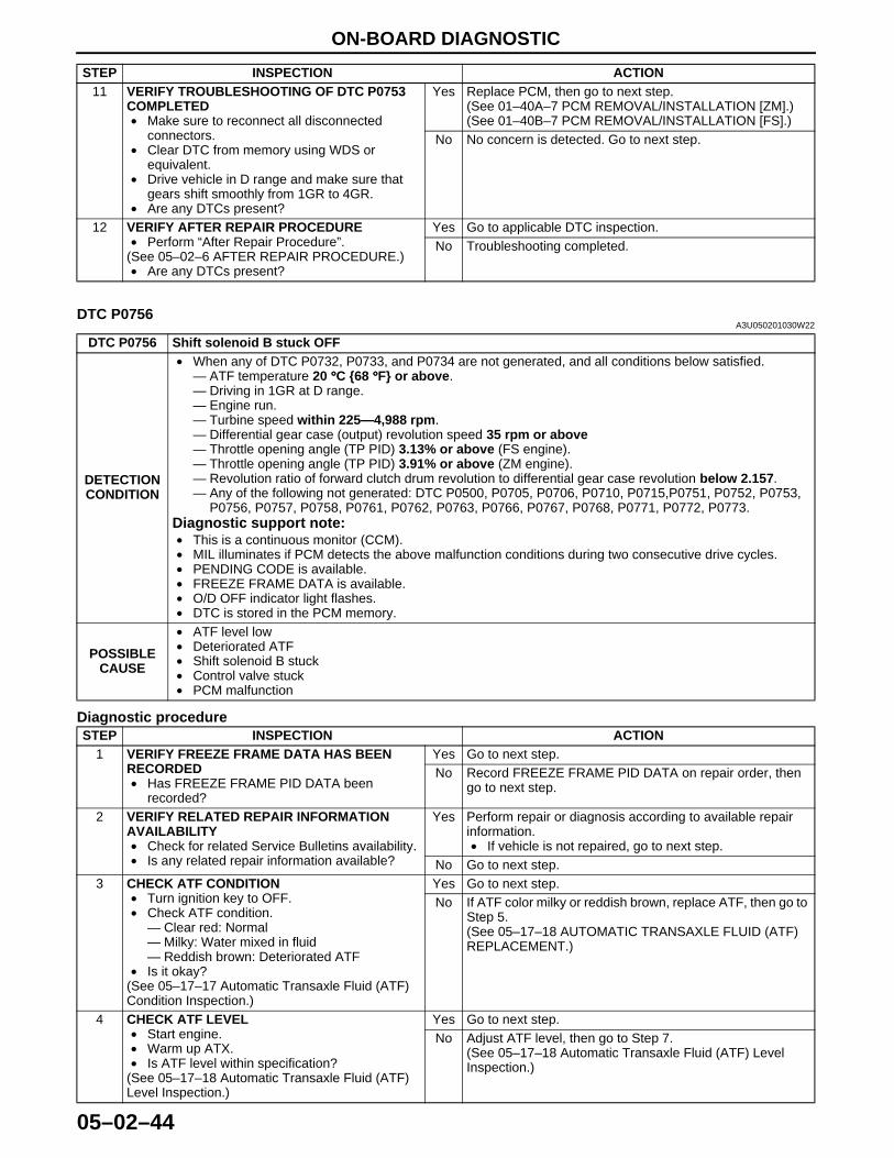
ON-BOARD DIAGNOSTIC
05–02–44
End Of SieDTC P0756
A3U050201030W22
Diagnostic procedure
11 VERIFY TROUBLESHOOTING OF DTC P0753 COMPLETED• Make sure to reconnect all disconnected
connectors.• Clear DTC from memory using WDS or
equivalent.• Drive vehicle in D range and make sure that
gears shift smoothly from 1GR to 4GR.• Are any DTCs present?
Yes Replace PCM, then go to next step.(See 01–40A–7 PCM REMOVAL/INSTALLATION [ZM].)(See 01–40B–7 PCM REMOVAL/INSTALLATION [FS].)
No No concern is detected. Go to next step.
12 VERIFY AFTER REPAIR PROCEDURE• Perform “After Repair Procedure”.
(See 05–02–6 AFTER REPAIR PROCEDURE.)• Are any DTCs present?
Yes Go to applicable DTC inspection.No Troubleshooting completed.
STEP INSPECTION ACTION
DTC P0756 Shift solenoid B stuck OFF
DETECTION CONDITION
• When any of DTC P0732, P0733, and P0734 are not generated, and all conditions below satisfied.— ATF temperature 20 °°°°C {68 °°°°F} or above.— Driving in 1GR at D range.— Engine run.— Turbine speed within 225—4,988 rpm.— Differential gear case (output) revolution speed 35 rpm or above— Throttle opening angle (TP PID) 3.13% or above (FS engine).— Throttle opening angle (TP PID) 3.91% or above (ZM engine).— Revolution ratio of forward clutch drum revolution to differential gear case revolution below 2.157.— Any of the following not generated: DTC P0500, P0705, P0706, P0710, P0715,P0751, P0752, P0753,
P0756, P0757, P0758, P0761, P0762, P0763, P0766, P0767, P0768, P0771, P0772, P0773.Diagnostic support note:• This is a continuous monitor (CCM).• MIL illuminates if PCM detects the above malfunction conditions during two consecutive drive cycles.• PENDING CODE is available.• FREEZE FRAME DATA is available.• O/D OFF indicator light flashes.• DTC is stored in the PCM memory.
POSSIBLE CAUSE
• ATF level low• Deteriorated ATF• Shift solenoid B stuck• Control valve stuck• PCM malfunction
STEP INSPECTION ACTION1 VERIFY FREEZE FRAME DATA HAS BEEN
RECORDED• Has FREEZE FRAME PID DATA been
recorded?
Yes Go to next step.No Record FREEZE FRAME PID DATA on repair order, then
go to next step.
2 VERIFY RELATED REPAIR INFORMATION AVAILABILITY• Check for related Service Bulletins availability.• Is any related repair information available?
Yes Perform repair or diagnosis according to available repair information.• If vehicle is not repaired, go to next step.
No Go to next step.3 CHECK ATF CONDITION
• Turn ignition key to OFF.• Check ATF condition.
— Clear red: Normal— Milky: Water mixed in fluid— Reddish brown: Deteriorated ATF
• Is it okay?(See 05–17–17 Automatic Transaxle Fluid (ATF) Condition Inspection.)
Yes Go to next step.No If ATF color milky or reddish brown, replace ATF, then go to
Step 5.(See 05–17–18 AUTOMATIC TRANSAXLE FLUID (ATF) REPLACEMENT.)
4 CHECK ATF LEVEL• Start engine.• Warm up ATX.• Is ATF level within specification?
(See 05–17–18 Automatic Transaxle Fluid (ATF) Level Inspection.)
Yes Go to next step.No Adjust ATF level, then go to Step 7.
(See 05–17–18 Automatic Transaxle Fluid (ATF) Level Inspection.)
1712-1U-01G(05-02).fm 44 ページ 2001年6月29日 金曜日 午後4時35分
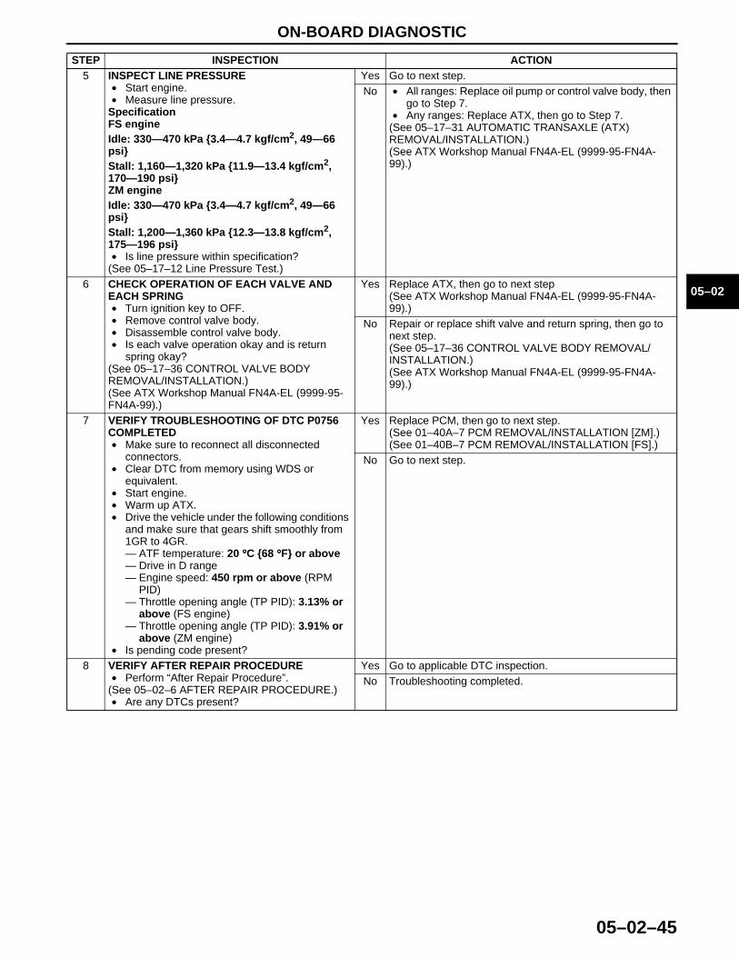
ON-BOARD DIAGNOSTIC
05–02–45
05–02
End Of Sie
5 INSPECT LINE PRESSURE• Start engine.• Measure line pressure.
SpecificationFS engineIdle: 330—470 kPa {3.4—4.7 kgf/cm2, 49—66 psi}Stall: 1,160—1,320 kPa {11.9—13.4 kgf/cm2, 170—190 psi}ZM engineIdle: 330—470 kPa {3.4—4.7 kgf/cm2, 49—66 psi}Stall: 1,200—1,360 kPa {12.3—13.8 kgf/cm2, 175—196 psi}• Is line pressure within specification?
(See 05–17–12 Line Pressure Test.)
Yes Go to next step.No • All ranges: Replace oil pump or control valve body, then
go to Step 7.• Any ranges: Replace ATX, then go to Step 7.
(See 05–17–31 AUTOMATIC TRANSAXLE (ATX) REMOVAL/INSTALLATION.)(See ATX Workshop Manual FN4A-EL (9999-95-FN4A-99).)
6 CHECK OPERATION OF EACH VALVE AND EACH SPRING• Turn ignition key to OFF.• Remove control valve body.• Disassemble control valve body.• Is each valve operation okay and is return
spring okay?(See 05–17–36 CONTROL VALVE BODY REMOVAL/INSTALLATION.)(See ATX Workshop Manual FN4A-EL (9999-95-FN4A-99).)
Yes Replace ATX, then go to next step(See ATX Workshop Manual FN4A-EL (9999-95-FN4A-99).)
No Repair or replace shift valve and return spring, then go to next step.(See 05–17–36 CONTROL VALVE BODY REMOVAL/INSTALLATION.)(See ATX Workshop Manual FN4A-EL (9999-95-FN4A-99).)
7 VERIFY TROUBLESHOOTING OF DTC P0756 COMPLETED• Make sure to reconnect all disconnected
connectors.• Clear DTC from memory using WDS or
equivalent.• Start engine.• Warm up ATX.• Drive the vehicle under the following conditions
and make sure that gears shift smoothly from 1GR to 4GR.— ATF temperature: 20 °°°°C {68 °°°°F} or above— Drive in D range— Engine speed: 450 rpm or above (RPM
PID)— Throttle opening angle (TP PID): 3.13% or
above (FS engine)— Throttle opening angle (TP PID): 3.91% or
above (ZM engine)• Is pending code present?
Yes Replace PCM, then go to next step.(See 01–40A–7 PCM REMOVAL/INSTALLATION [ZM].)(See 01–40B–7 PCM REMOVAL/INSTALLATION [FS].)
No Go to next step.
8 VERIFY AFTER REPAIR PROCEDURE• Perform “After Repair Procedure”.
(See 05–02–6 AFTER REPAIR PROCEDURE.)• Are any DTCs present?
Yes Go to applicable DTC inspection.No Troubleshooting completed.
STEP INSPECTION ACTION
1712-1U-01G(05-02).fm 45 ページ 2001年6月29日 金曜日 午後4時35分
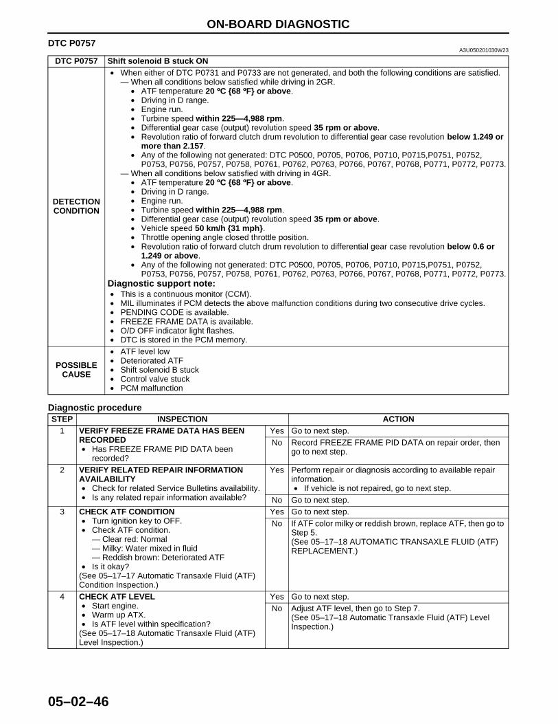
ON-BOARD DIAGNOSTIC
05–02–46
DTC P0757A3U050201030W23
Diagnostic procedure
DTC P0757 Shift solenoid B stuck ON
DETECTION CONDITION
• When either of DTC P0731 and P0733 are not generated, and both the following conditions are satisfied.— When all conditions below satisfied while driving in 2GR.
• ATF temperature 20 °°°°C {68 °°°°F} or above.• Driving in D range.• Engine run.• Turbine speed within 225—4,988 rpm.• Differential gear case (output) revolution speed 35 rpm or above.• Revolution ratio of forward clutch drum revolution to differential gear case revolution below 1.249 or
more than 2.157.• Any of the following not generated: DTC P0500, P0705, P0706, P0710, P0715,P0751, P0752,
P0753, P0756, P0757, P0758, P0761, P0762, P0763, P0766, P0767, P0768, P0771, P0772, P0773.— When all conditions below satisfied with driving in 4GR.
• ATF temperature 20 °°°°C {68 °°°°F} or above.• Driving in D range.• Engine run.• Turbine speed within 225—4,988 rpm.• Differential gear case (output) revolution speed 35 rpm or above.• Vehicle speed 50 km/h {31 mph}.• Throttle opening angle closed throttle position.• Revolution ratio of forward clutch drum revolution to differential gear case revolution below 0.6 or
1.249 or above.• Any of the following not generated: DTC P0500, P0705, P0706, P0710, P0715,P0751, P0752,
P0753, P0756, P0757, P0758, P0761, P0762, P0763, P0766, P0767, P0768, P0771, P0772, P0773.Diagnostic support note:• This is a continuous monitor (CCM).• MIL illuminates if PCM detects the above malfunction conditions during two consecutive drive cycles.• PENDING CODE is available.• FREEZE FRAME DATA is available.• O/D OFF indicator light flashes.• DTC is stored in the PCM memory.
POSSIBLE CAUSE
• ATF level low• Deteriorated ATF• Shift solenoid B stuck• Control valve stuck• PCM malfunction
STEP INSPECTION ACTION1 VERIFY FREEZE FRAME DATA HAS BEEN
RECORDED• Has FREEZE FRAME PID DATA been
recorded?
Yes Go to next step.No Record FREEZE FRAME PID DATA on repair order, then
go to next step.
2 VERIFY RELATED REPAIR INFORMATION AVAILABILITY• Check for related Service Bulletins availability.• Is any related repair information available?
Yes Perform repair or diagnosis according to available repair information.• If vehicle is not repaired, go to next step.
No Go to next step.3 CHECK ATF CONDITION
• Turn ignition key to OFF.• Check ATF condition.
— Clear red: Normal— Milky: Water mixed in fluid— Reddish brown: Deteriorated ATF
• Is it okay?(See 05–17–17 Automatic Transaxle Fluid (ATF) Condition Inspection.)
Yes Go to next step.No If ATF color milky or reddish brown, replace ATF, then go to
Step 5.(See 05–17–18 AUTOMATIC TRANSAXLE FLUID (ATF) REPLACEMENT.)
4 CHECK ATF LEVEL• Start engine.• Warm up ATX.• Is ATF level within specification?
(See 05–17–18 Automatic Transaxle Fluid (ATF) Level Inspection.)
Yes Go to next step.No Adjust ATF level, then go to Step 7.
(See 05–17–18 Automatic Transaxle Fluid (ATF) Level Inspection.)
1712-1U-01G(05-02).fm 46 ページ 2001年6月29日 金曜日 午後4時35分

ON-BOARD DIAGNOSTIC
05–02–47
05–02
End Of Sie
5 INSPECT LINE PRESSURE• Start engine.• Measure line pressure.
SpecificationFS engineIdle: 330—470 kPa {3.4—4.7 kgf/cm2, 49—66 psi}Stall: 1,160—1,320 kPa {11.9—13.4 kgf/cm2, 170—190 psi}ZM engineIdle: 330—470 kPa {3.4—4.7 kgf/cm2, 49—66 psi}Stall: 1,200—1,360 kPa {12.3—13.8 kgf/cm2, 175—196 psi}• Is line pressure within specification?
(See 05–17–12 Line Pressure Test.)
Yes Go to next step.No • All ranges: Replace oil pump or control valve body, then
go to Step 7.• Any ranges: Replace ATX, then go to Step 7.
(See 05–17–31 AUTOMATIC TRANSAXLE (ATX) REMOVAL/INSTALLATION.)(See ATX Workshop Manual FN4A-EL (9999-95-FN4A-99).)
6 CHECK OPERATION OF EACH VALVE AND EACH SPRING• Turn ignition key to OFF.• Remove control valve body.• Disassemble control valve body.• Is each valve operation okay and is return
spring okay?(See 05–17–36 CONTROL VALVE BODY REMOVAL/INSTALLATION.)(See ATX Workshop Manual FN4A-EL (9999-95-FN4A-99).)
Yes Replace ATX, then go to next step(See ATX Workshop Manual FN4A-EL (9999-95-FN4A-99).)
No Repair or replace shift valve and return spring, then go to next step.(See 05–17–36 CONTROL VALVE BODY REMOVAL/INSTALLATION.)(See ATX Workshop Manual FN4A-EL (9999-95-FN4A-99).)
7 VERIFY TROUBLESHOOTING OF DTC P0757 COMPLETED• Make sure to reconnect all disconnected
connectors.• Clear DTC from memory using WDS or
equivalent.• Start engine.• Warm up ATX.• Drive the vehicle under the following conditions
make sure that gears shift smoothly from 1GR to 4GR.— ATF temperature: 20 °°°°C {68 °°°°F} or above— Drive in D range— Engine speed: 450 rpm or above (RPM
PID)— Throttle opening angle (TP PID): 0% (4th
gear only)— Vehicle speed (VSS PID): 50 km/h {31
mph} (4th gear only)• Is pending code present?
Yes Replace PCM, then go to next step.(See 01–40A–7 PCM REMOVAL/INSTALLATION [ZM].)(See 01–40B–7 PCM REMOVAL/INSTALLATION [FS].)
No Go to next step.
8 VERIFY AFTER REPAIR PROCEDURE• Perform “After Repair Procedure”.
(See 05–02–6 AFTER REPAIR PROCEDURE.)• Are any DTCs present?
Yes Go to applicable DTC inspection.No Troubleshooting completed.
STEP INSPECTION ACTION
1712-1U-01G(05-02).fm 47 ページ 2001年6月29日 金曜日 午後4時35分
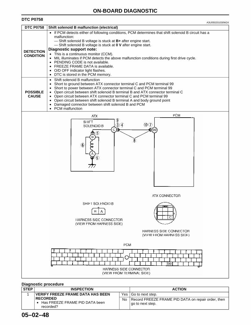
ON-BOARD DIAGNOSTIC
05–02–48
DTC P0758A3U050201030W24
Diagnostic procedure
DTC P0758 Shift solenoid B malfunction (electrical)
DETECTION CONDITION
• If PCM detects either of following conditions, PCM determines that shift solenoid B circuit has a malfunction:— Shift solenoid B voltage is stuck at B+ after engine start.— Shift solenoid B voltage is stuck at 0 V after engine start.
Diagnostic support note:• This is a continuous monitor (CCM).• MIL illuminates if PCM detects the above malfunction conditions during first drive cycle.• PENDING CODE is not available.• FREEZE FRAME DATA is available.• O/D OFF indicator light flashes.• DTC is stored in the PCM memory.
POSSIBLE CAUSE
• Shift solenoid B malfunction• Short to ground between ATX connector terminal C and PCM terminal 99• Short to power between ATX connector terminal C and PCM terminal 99• Open circuit between shift solenoid B terminal B and ATX connector terminal C• Open circuit between ATX connector terminal C and PCM terminal 99• Open circuit between shift solenoid B terminal A and body ground point• Damaged connector between shift solenoid B and PCM• PCM malfunction
STEP INSPECTION ACTION1 VERIFY FREEZE FRAME DATA HAS BEEN
RECORDED• Has FREEZE FRAME PID DATA been
recorded?
Yes Go to next step.No Record FREEZE FRAME PID DATA on repair order, then
go to next step.
1712-1U-01G(05-02).fm 48 ページ 2001年6月29日 金曜日 午後4時35分
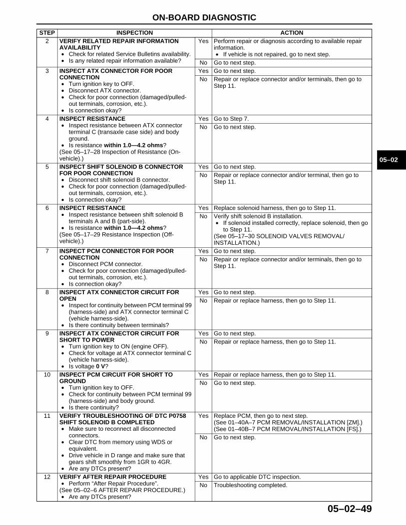
ON-BOARD DIAGNOSTIC
05–02–49
05–02
2 VERIFY RELATED REPAIR INFORMATION AVAILABILITY• Check for related Service Bulletins availability.• Is any related repair information available?
Yes Perform repair or diagnosis according to available repair information.• If vehicle is not repaired, go to next step.
No Go to next step.3 INSPECT ATX CONNECTOR FOR POOR
CONNECTION• Turn ignition key to OFF.• Disconnect ATX connector.• Check for poor connection (damaged/pulled-
out terminals, corrosion, etc.).• Is connection okay?
Yes Go to next step.No Repair or replace connector and/or terminals, then go to
Step 11.
4 INSPECT RESISTANCE• Inspect resistance between ATX connector
terminal C (transaxle case side) and body ground.
• Is resistance within 1.0—4.2 ohms?(See 05–17–28 Inspection of Resistance (On-vehicle).)
Yes Go to Step 7.No Go to next step.
5 INSPECT SHIFT SOLENOID B CONNECTOR FOR POOR CONNECTION• Disconnect shift solenoid B connector.• Check for poor connection (damaged/pulled-
out terminals, corrosion, etc.).• Is connection okay?
Yes Go to next step.No Repair or replace connector and/or terminal, then go to
Step 11.
6 INSPECT RESISTANCE• Inspect resistance between shift solenoid B
terminals A and B (part-side).• Is resistance within 1.0—4.2 ohms?
(See 05–17–29 Resistance Inspection (Off-vehicle).)
Yes Replace solenoid harness, then go to Step 11.No Verify shift solenoid B installation.
• If solenoid installed correctly, replace solenoid, then go to Step 11.
(See 05–17–30 SOLENOID VALVES REMOVAL/INSTALLATION.)
7 INSPECT PCM CONNECTOR FOR POOR CONNECTION• Disconnect PCM connector.• Check for poor connection (damaged/pulled-
out terminals, corrosion, etc.).• Is connection okay?
Yes Go to next step.No Repair or replace connector and/or terminals, then go to
Step 11.
8 INSPECT ATX CONNECTOR CIRCUIT FOR OPEN• Inspect for continuity between PCM terminal 99
(harness-side) and ATX connector terminal C (vehicle harness-side).
• Is there continuity between terminals?
Yes Go to next step.No Repair or replace harness, then go to Step 11.
9 INSPECT ATX CONNECTOR CIRCUIT FOR SHORT TO POWER• Turn ignition key to ON (engine OFF).• Check for voltage at ATX connector terminal C
(vehicle harness-side).• Is voltage 0 V?
Yes Go to next step.No Repair or replace harness, then go to Step 11.
10 INSPECT PCM CIRCUIT FOR SHORT TO GROUND• Turn ignition key to OFF.• Check for continuity between PCM terminal 99
(harness-side) and body ground.• Is there continuity?
Yes Repair or replace harness, then go to Step 11.No Go to next step.
11 VERIFY TROUBLESHOOTING OF DTC P0758 SHIFT SOLENOID B COMPLETED• Make sure to reconnect all disconnected
connectors.• Clear DTC from memory using WDS or
equivalent.• Drive vehicle in D range and make sure that
gears shift smoothly from 1GR to 4GR.• Are any DTCs present?
Yes Replace PCM, then go to next step.(See 01–40A–7 PCM REMOVAL/INSTALLATION [ZM].)(See 01–40B–7 PCM REMOVAL/INSTALLATION [FS].)
No Go to next step.
12 VERIFY AFTER REPAIR PROCEDURE• Perform “After Repair Procedure”.
(See 05–02–6 AFTER REPAIR PROCEDURE.)• Are any DTCs present?
Yes Go to applicable DTC inspection.No Troubleshooting completed.
STEP INSPECTION ACTION
1712-1U-01G(05-02).fm 49 ページ 2001年6月29日 金曜日 午後4時35分
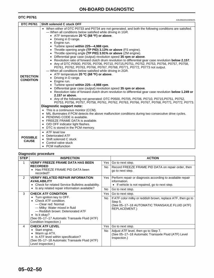
ON-BOARD DIAGNOSTIC
05–02–50
End Of Sie
DTC P0761A3U050201030W25
Diagnostic procedure
DTC P0761 Shift solenoid C stuck OFF
DETECTION CONDITION
• When either of DTC P0733 and P0734 are not generated, and both the following conditions are satisfied.— When all conditions below satisfied while driving in 1GR.
• ATF temperature 20 °°°°C {68 °°°°F} or above.• Driving in D range.• Engine run.• Turbine speed within 225—4,988 rpm.• Throttle opening angle (TP PID) 3.13% or above (FS engine).• Throttle opening angle (TP PID) 3.91% or above (ZM engine).• Differential gear case (output) revolution speed 35 rpm or above.• Revolution ratio of forward clutch drum revolution to differential gear case revolution below 2.157.• Any of DTC P0500, P0705, P0706, P0710, P0715,P0751, P0752, P0753, P0756, P0757, P0758,
P0761, P0762, P0763, P0766, P0767, P0768, P0771, P0772, P0773 not output.— When all conditions below satisfied while driving in 2GR.
• ATF temperature 20 °°°°C {68 °°°°F} or above.• Driving in D range.• Engine run.• Turbine speed within 225—4,988 rpm.• Differential gear case (output) revolution speed 35 rpm or above.• Revolution ratio of forward clutch drum revolution to differential gear case revolution below 1.249 or
2.157 or above.• Any of the following not generated: DTC P0500, P0705, P0706, P0710, P0715,P0751, P0752,
P0753, P0756, P0757, P0758, P0761, P0762, P0763, P0766, P0767, P0768, P0771, P0772, P0773.Diagnostic support note:• This is a continuous monitor (CCM).• MIL illuminates if PCM detects the above malfunction conditions during two consecutive drive cycles.• PENDING CODE is available.• FREEZE FRAME DATA is available.• O/D OFF indicator light flashes.• DTC is stored in the PCM memory.
POSSIBLE CAUSE
• ATF level low• Deteriorated ATF• Shift solenoid C stuck• Control valve stuck• PCM malfunction
STEP INSPECTION ACTION1 VERIFY FREEZE FRAME DATA HAS BEEN
RECORDED• Has FREEZE FRAME PID DATA been
recorded?
Yes Go to next step.No Record FREEZE FRAME PID DATA on repair order, then
go to next step.
2 VERIFY RELATED REPAIR INFORMATION AVAILABILITY• Check for related Service Bulletins availability.• Is any related repair information available?
Yes Perform repair or diagnosis according to available repair information.• If vehicle is not repaired, go to next step.
No Go to next step.3 CHECK ATF CONDITION
• Turn ignition key to OFF.• Check ATF condition.
— Clear red: Normal— Milky: Water mixed in fluid— Reddish brown: Deteriorated ATF
• Is it okay?(See 05–17–17 Automatic Transaxle Fluid (ATF) Condition Inspection.)
Yes Go to next step.No If ATF color milky or reddish brown, replace ATF, then go to
Step 5.(See 05–17–18 AUTOMATIC TRANSAXLE FLUID (ATF) REPLACEMENT.)
4 CHECK ATF LEVEL• Start engine.• Warm up ATX.• Is ATF level within specification?
(See 05–17–18 Automatic Transaxle Fluid (ATF) Level Inspection.)
Yes Go to next step.No Adjust ATF level, then go to Step 7.
(See 05–17–18 Automatic Transaxle Fluid (ATF) Level Inspection.)
1712-1U-01G(05-02).fm 50 ページ 2001年6月29日 金曜日 午後4時35分
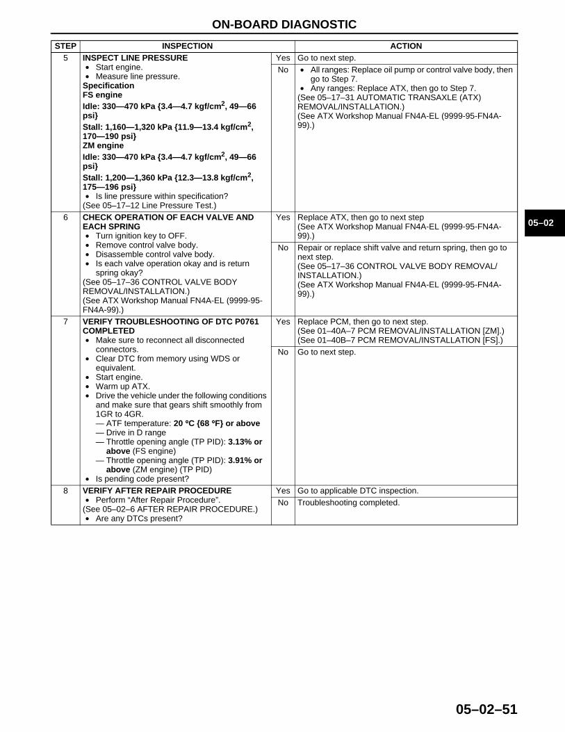
ON-BOARD DIAGNOSTIC
05–02–51
05–02
End Of Sie
5 INSPECT LINE PRESSURE• Start engine.• Measure line pressure.
SpecificationFS engineIdle: 330—470 kPa {3.4—4.7 kgf/cm2, 49—66 psi}Stall: 1,160—1,320 kPa {11.9—13.4 kgf/cm2, 170—190 psi}ZM engineIdle: 330—470 kPa {3.4—4.7 kgf/cm2, 49—66 psi}Stall: 1,200—1,360 kPa {12.3—13.8 kgf/cm2, 175—196 psi}• Is line pressure within specification?
(See 05–17–12 Line Pressure Test.)
Yes Go to next step.No • All ranges: Replace oil pump or control valve body, then
go to Step 7.• Any ranges: Replace ATX, then go to Step 7.
(See 05–17–31 AUTOMATIC TRANSAXLE (ATX) REMOVAL/INSTALLATION.)(See ATX Workshop Manual FN4A-EL (9999-95-FN4A-99).)
6 CHECK OPERATION OF EACH VALVE AND EACH SPRING• Turn ignition key to OFF.• Remove control valve body.• Disassemble control valve body.• Is each valve operation okay and is return
spring okay?(See 05–17–36 CONTROL VALVE BODY REMOVAL/INSTALLATION.)(See ATX Workshop Manual FN4A-EL (9999-95-FN4A-99).)
Yes Replace ATX, then go to next step(See ATX Workshop Manual FN4A-EL (9999-95-FN4A-99).)
No Repair or replace shift valve and return spring, then go to next step.(See 05–17–36 CONTROL VALVE BODY REMOVAL/INSTALLATION.)(See ATX Workshop Manual FN4A-EL (9999-95-FN4A-99).)
7 VERIFY TROUBLESHOOTING OF DTC P0761 COMPLETED• Make sure to reconnect all disconnected
connectors.• Clear DTC from memory using WDS or
equivalent.• Start engine.• Warm up ATX.• Drive the vehicle under the following conditions
and make sure that gears shift smoothly from 1GR to 4GR.— ATF temperature: 20 °°°°C {68 °°°°F} or above— Drive in D range— Throttle opening angle (TP PID): 3.13% or
above (FS engine)— Throttle opening angle (TP PID): 3.91% or
above (ZM engine) (TP PID)• Is pending code present?
Yes Replace PCM, then go to next step.(See 01–40A–7 PCM REMOVAL/INSTALLATION [ZM].)(See 01–40B–7 PCM REMOVAL/INSTALLATION [FS].)
No Go to next step.
8 VERIFY AFTER REPAIR PROCEDURE• Perform “After Repair Procedure”.
(See 05–02–6 AFTER REPAIR PROCEDURE.)• Are any DTCs present?
Yes Go to applicable DTC inspection.No Troubleshooting completed.
STEP INSPECTION ACTION
1712-1U-01G(05-02).fm 51 ページ 2001年6月29日 金曜日 午後4時35分

ON-BOARD DIAGNOSTIC
05–02–52
DTC P0762A3U050201030W26
Diagnostic procedure
DTC P0762 Shift solenoid C stuck ON
DETECTION CONDITION
• When either of DTC P0731 and P0732 are not generated, and both the following conditions are satisfied.— When all conditions below satisfied while driving in 3GR.
• ATF temperature 20 °°°°C {68 °°°°F} or above.• Driving in D range.• Engine run.• Turbine speed within 225—4,988 rpm.• Differential gear case (output) revolution speed 35 rpm or above.• Revolution ratio of forward clutch drum revolution to differential gear case revolution below 0.863 or
1.249 or above.• Any of the following not generated: DTC P0500, P0705, P0706, P0710, P0715,P0751, P0752,
P0753, P0756, P0757, P0758, P0761, P0762, P0763, P0766, P0767, P0768, P0771, P0772, P0773.— When all conditions below satisfied while driving in 4GR.
• ATF temperature 20 °°°°C {68 °°°°F} or above.• Driving in D range.• Engine run.• Turbine speed within 225—4,988 rpm.• Vehicle speed 50 km/h {31mph} or above.• Differential gear case (output) revolution speed 35 rpm or above.• Throttle opening angle at closed throttle position• Revolution ratio of forward clutch drum revolution to differential gear case revolution below 0.6 or
1.249 or above.• Any of the following not generated: DTC P0500, P0705, P0706, P0710, P0715,P0751, P0752,
P0753, P0756, P0757, P0758, P0761, P0762, P0763, P0766, P0767, P0768, P0771, P0772, P0773.Diagnostic support note:• This is a continuous monitor (CCM).• MIL illuminates if PCM detects the above malfunction conditions during two consecutive drive cycles.• PENDING CODE is available.• FREEZE FRAME DATA is available.• O/D OFF indicator light flashes.• DTC is stored in the PCM memory.
POSSIBLE CAUSE
• ATF level low• Deteriorated ATF• Shift solenoid C and pressure control solenoid stuck• Control valve stuck• PCM malfunction
STEP INSPECTION ACTION1 VERIFY FREEZE FRAME DATA HAS BEEN
RECORDED• Has FREEZE FRAME PID DATA been
recorded?
Yes Go to next step.No Record FREEZE FRAME PID DATA on repair order, then
go to next step.
2 VERIFY RELATED REPAIR INFORMATION AVAILABILITY• Check for related Service Bulletins availability.• Is any related repair information available?
Yes Perform repair or diagnosis according to available repair information.• If vehicle is not repaired, go to next step.
No Go to next step.3 CHECK ATF CONDITION
• Turn ignition key to OFF.• Check ATF condition.
— Clear red: Normal— Milky: Water mixed in fluid— Reddish brown: Deteriorated ATF
• Is it okay?(See 05–17–17 Automatic Transaxle Fluid (ATF) Condition Inspection.)
Yes Go to next step.No If ATF color milky or reddish brown, replace ATF, then go to
Step 5.(See 05–17–18 AUTOMATIC TRANSAXLE FLUID (ATF) REPLACEMENT.)
4 CHECK ATF LEVEL• Start engine.• Warm up ATX.• Is ATF level within specification?
(See 05–17–18 Automatic Transaxle Fluid (ATF) Level Inspection.)
Yes Go to next step.No Adjust ATF level, then go to Step 7.
(See 05–17–18 Automatic Transaxle Fluid (ATF) Level Inspection.)
1712-1U-01G(05-02).fm 52 ページ 2001年6月29日 金曜日 午後4時35分

ON-BOARD DIAGNOSTIC
05–02–53
05–02
End Of Sie
5 INSPECT LINE PRESSURE• Start engine.• Measure line pressure.
SpecificationFS engineIdle: 330—470 kPa {3.4—4.7 kgf/cm2, 49—66 psi}Stall: 1,160—1,320 kPa {11.9—13.4 kgf/cm2, 170—190 psi}ZM engineIdle: 330—470 kPa {3.4—4.7 kgf/cm2, 49—66 psi}Stall: 1,200—1,360 kPa {12.3—13.8 kgf/cm2, 175—196 psi}• Is line pressure within specification?
(See 05–17–12 Line Pressure Test.)
Yes Go to next step.No • All ranges: Replace oil pump or control valve body, then
go to Step 7.• Any ranges: Replace ATX, then go to Step 7.
(See 05–17–31 AUTOMATIC TRANSAXLE (ATX) REMOVAL/INSTALLATION.)(See ATX Workshop Manual FN4A-EL (9999-95-FN4A-99).)
6 CHECK OPERATION OF EACH VALVE AND EACH SPRING• Turn ignition key to OFF.• Remove control valve body.• Disassemble control valve body.• Is each valve operation okay and is return
spring okay?(See 05–17–36 CONTROL VALVE BODY REMOVAL/INSTALLATION.)(See ATX Workshop Manual FN4A-EL (9999-95-FN4A-99).)
Yes Replace ATX, then go to next step(See ATX Workshop Manual FN4A-EL (9999-95-FN4A-99).)
No Repair or replace shift valve and return spring, then go to next step.(See 05–17–36 CONTROL VALVE BODY REMOVAL/INSTALLATION.)(See ATX Workshop Manual FN4A-EL (9999-95-FN4A-99).)
7 VERIFY TROUBLESHOOTING OF DTC P0762 COMPLETED• Make sure to reconnect all disconnected
connectors.• Clear DTC from memory using WDS or
equivalent.• Start engine.• Warm up ATX.• Drive the vehicle under the following conditions
and make sure that gears shift smoothly from 1GR to 4GR.— ATF temperature: 20 °°°°C {68 °°°°F} or above— Drive in D range— Throttle opening angle (TP PID): 0% (4GR
only)— Vehicle speed (VSS PID): 50 km/h {31
mph} or above (4GR only)• Is pending code present?
Yes Replace PCM, then go to next step.(See 01–40A–7 PCM REMOVAL/INSTALLATION [ZM].)(See 01–40B–7 PCM REMOVAL/INSTALLATION [FS].)
No Go to next step.
8 VERIFY AFTER REPAIR PROCEDURE• Perform “After Repair Procedure”.
(See 05–02–6 AFTER REPAIR PROCEDURE.)• Are any DTCs present?
Yes Go to applicable DTC inspection.No Troubleshooting completed.
STEP INSPECTION ACTION
1712-1U-01G(05-02).fm 53 ページ 2001年6月29日 金曜日 午後4時35分
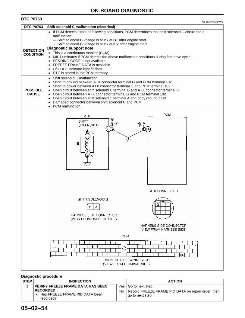
ON-BOARD DIAGNOSTIC
05–02–54
DTC P0763A3U050201030W27
Diagnostic procedure
DTC P0763 Shift solenoid C malfunction (electrical)
DETECTION CONDITION
• If PCM detects either of following conditions, PCM determines that shift solenoid C circuit has a malfunction:— Shift solenoid C voltage is stuck at B+ after engine start.— Shift solenoid C voltage is stuck at 0 V after engine start.
Diagnostic support note:• This is a continuous monitor (CCM).• MIL illuminates if PCM detects the above malfunction conditions during first drive cycle.• PENDING CODE is not available.• FREEZE FRAME DATA is available.• O/D OFF indicator light flashes.• DTC is stored in the PCM memory.
POSSIBLE CAUSE
• Shift solenoid C malfunction• Short to ground between ATX connector terminal G and PCM terminal 102• Short to power between ATX connector terminal G and PCM terminal 102• Open circuit between shift solenoid C terminal B and ATX connector terminal G• Open circuit between ATX connector terminal G and PCM terminal 102• Open circuit between shift solenoid C terminal A and body ground point• Damaged connector between shift solenoid C and PCM.• PCM malfunction.
STEP INSPECTION ACTION1 VERIFY FREEZE FRAME DATA HAS BEEN
RECORDED• Has FREEZE FRAME PID DATA been
recorded?
Yes Go to next step.No Record FREEZE FRAME PID DATA on repair order, then
go to next step.
1712-1U-01G(05-02).fm 54 ページ 2001年6月29日 金曜日 午後4時35分
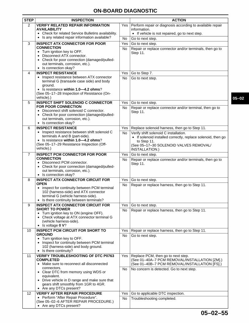
ON-BOARD DIAGNOSTIC
05–02–55
05–02
2 VERIFY RELATED REPAIR INFORMATION AVAILABILITY• Check for related Service Bulletins availability.• Is any related repair information available?
Yes Perform repair or diagnosis according to available repair information.• If vehicle is not repaired, go to next step.
No Go to next step.3 INSPECT ATX CONNECTOR FOR POOR
CONNECTION• Turn ignition key to OFF.• Disconnect ATX connector.• Check for poor connection (damaged/pulled-
out terminals, corrosion, etc.).• Is connection okay?
Yes Go to next step.No Repair or replace connector and/or terminals, then go to
Step 11.
4 INSPECT RESISTANCE• Inspect resistance between ATX connector
terminal G (transaxle case side) and body ground.
• Is resistance within 1.0—4.2 ohms?(See 05–17–28 Inspection of Resistance (On-vehicle).)
Yes Go to Step 7.No Go to next step.
5 INSPECT SHIFT SOLENOID C CONNECTOR FOR POOR CONNECTION• Disconnect shift solenoid C connector.• Check for poor connection (damaged/pulled-
out terminals, corrosion, etc.).• Is connection okay?
Yes Go to next step.No Repair or replace connector and/or terminal, then go to
Step 11.
6 INSPECT RESISTANCE• Inspect resistance between shift solenoid C
terminals A and B (part-side).• Is resistance within 1.0—4.2 ohms?
(See 05–17–29 Resistance Inspection (Off-vehicle).)
Yes Replace solenoid harness, then go to Step 11.No Verify shift solenoid C installation.
• If solenoid installed correctly, replace solenoid, then go to Step 11.
(See 05–17–30 SOLENOID VALVES REMOVAL/INSTALLATION.)
7 INSPECT PCM CONNECTOR FOR POOR CONNECTION• Disconnect PCM connector.• Check for poor connection (damaged/pulled-
out terminals, corrosion, etc.).• Is connection okay?
Yes Go to next step.No Repair or replace connector and/or terminals, then go to
Step 11.
8 INSPECT ATX CONNECTOR CIRCUIT FOR OPEN• inspect for continuity between PCM terminal
102 (harness-side) and ATX connector terminal G (vehicle harness-side).
• Is there continuity between terminals?
Yes Go to next step.No Repair or replace harness, then go to Step 11.
9 INSPECT ATX CONNECTOR CIRCUIT FOR SHORT TO POWER• Turn ignition key to ON (engine OFF).• Check voltage at ATX connector terminal G
(vehicle harness-side).• Is voltage 0 V?
Yes Go to next step.No Repair or replace harness, then go to Step 11.
10 INSPECT PCM CIRCUIT FOR SHORT TO GROUND• Turn ignition key to OFF.• Inspect for continuity between PCM terminal
102 (harness-side) and body ground.• Is there continuity?
Yes Repair or replace harness, then go to Step 11.No Go to next step.
11 VERIFY TROUBLESHOOTING OF DTC P0763 COMPLETED• Make sure to reconnect all disconnected
connectors.• Clear DTC from memory using WDS or
equivalent.• Drive vehicle in D range and make sure that
gears shift smoothly from 1GR to 4GR.• Are any DTCs present?
Yes Replace PCM, then go to next step.(See 01–40A–7 PCM REMOVAL/INSTALLATION [ZM].)(See 01–40B–7 PCM REMOVAL/INSTALLATION [FS].)
No No concern is detected. Go to next step.
12 VERIFY AFTER REPAIR PROCEDURE• Perform “After Repair Procedure”.
(See 05–02–6 AFTER REPAIR PROCEDURE.)• Are any DTCs present?
Yes Go to applicable DTC inspection.No Troubleshooting completed.
STEP INSPECTION ACTION
1712-1U-01G(05-02).fm 55 ページ 2001年6月29日 金曜日 午後4時35分
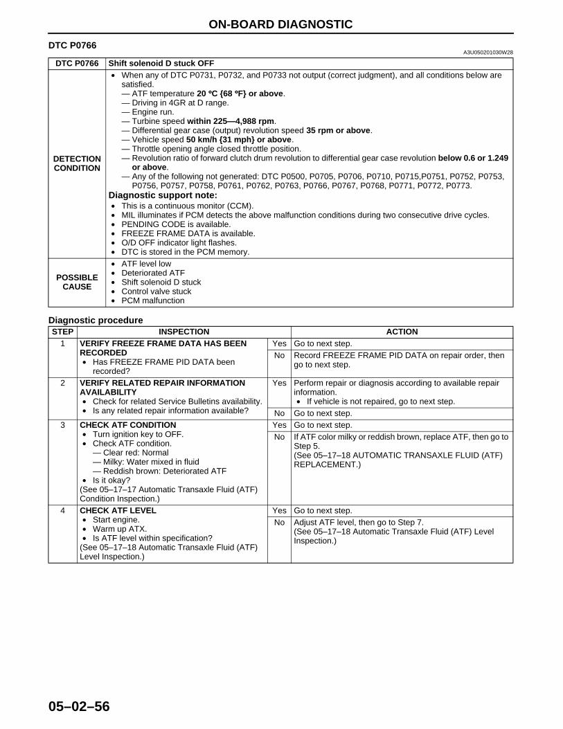
ON-BOARD DIAGNOSTIC
05–02–56
End Of Sie
DTC P0766A3U050201030W28
Diagnostic procedure
DTC P0766 Shift solenoid D stuck OFF
DETECTION CONDITION
• When any of DTC P0731, P0732, and P0733 not output (correct judgment), and all conditions below are satisfied.— ATF temperature 20 °°°°C {68 °°°°F} or above.— Driving in 4GR at D range.— Engine run.— Turbine speed within 225—4,988 rpm.— Differential gear case (output) revolution speed 35 rpm or above.— Vehicle speed 50 km/h {31 mph} or above.— Throttle opening angle closed throttle position.— Revolution ratio of forward clutch drum revolution to differential gear case revolution below 0.6 or 1.249
or above.— Any of the following not generated: DTC P0500, P0705, P0706, P0710, P0715,P0751, P0752, P0753,
P0756, P0757, P0758, P0761, P0762, P0763, P0766, P0767, P0768, P0771, P0772, P0773.Diagnostic support note:• This is a continuous monitor (CCM).• MIL illuminates if PCM detects the above malfunction conditions during two consecutive drive cycles.• PENDING CODE is available.• FREEZE FRAME DATA is available.• O/D OFF indicator light flashes.• DTC is stored in the PCM memory.
POSSIBLE CAUSE
• ATF level low• Deteriorated ATF• Shift solenoid D stuck• Control valve stuck• PCM malfunction
STEP INSPECTION ACTION1 VERIFY FREEZE FRAME DATA HAS BEEN
RECORDED• Has FREEZE FRAME PID DATA been
recorded?
Yes Go to next step.No Record FREEZE FRAME PID DATA on repair order, then
go to next step.
2 VERIFY RELATED REPAIR INFORMATION AVAILABILITY• Check for related Service Bulletins availability.• Is any related repair information available?
Yes Perform repair or diagnosis according to available repair information.• If vehicle is not repaired, go to next step.
No Go to next step.3 CHECK ATF CONDITION
• Turn ignition key to OFF.• Check ATF condition.
— Clear red: Normal— Milky: Water mixed in fluid— Reddish brown: Deteriorated ATF
• Is it okay?(See 05–17–17 Automatic Transaxle Fluid (ATF) Condition Inspection.)
Yes Go to next step.No If ATF color milky or reddish brown, replace ATF, then go to
Step 5.(See 05–17–18 AUTOMATIC TRANSAXLE FLUID (ATF) REPLACEMENT.)
4 CHECK ATF LEVEL• Start engine.• Warm up ATX.• Is ATF level within specification?
(See 05–17–18 Automatic Transaxle Fluid (ATF) Level Inspection.)
Yes Go to next step.No Adjust ATF level, then go to Step 7.
(See 05–17–18 Automatic Transaxle Fluid (ATF) Level Inspection.)
1712-1U-01G(05-02).fm 56 ページ 2001年6月29日 金曜日 午後4時35分

ON-BOARD DIAGNOSTIC
05–02–57
05–02
End Of Sie
5 INSPECT LINE PRESSURE• Start engine.• Measure line pressure.
SpecificationFS engineIdle: 330—470 kPa {3.4—4.7 kgf/cm2, 49—66 psi}Stall: 1,160—1,320 kPa {11.9—13.4 kgf/cm2, 170—190 psi}ZM engineIdle: 330—470 kPa {3.4—4.7 kgf/cm2, 49—66 psi}Stall: 1,200—1,360 kPa {12.3—13.8 kgf/cm2, 175—196 psi}• Is line pressure within specification?
(See 05–17–12 Line Pressure Test.)
Yes Go to next step.No • All ranges: Replace oil pump or control valve body, then
go to Step 7.• Any ranges: Replace ATX, then go to Step 7.
(See 05–17–31 AUTOMATIC TRANSAXLE (ATX) REMOVAL/INSTALLATION.)(See ATX Workshop Manual FN4A-EL (9999-95-FN4A-99).)
6 CHECK OPERATION OF EACH VALVE AND EACH SPRING• Turn ignition key to OFF.• Remove control valve body.• Disassemble control valve body.• Is each valve operation okay and is return
spring okay?(See 05–17–36 CONTROL VALVE BODY REMOVAL/INSTALLATION.)(See ATX Workshop Manual FN4A-EL (9999-95-FN4A-99).)
Yes Replace ATX, then go to next step(See ATX Workshop Manual FN4A-EL (9999-95-FN4A-99).)
No Repair or replace shift valve and return spring, then go to next step.(See 05–17–36 CONTROL VALVE BODY REMOVAL/INSTALLATION.)(See ATX Workshop Manual FN4A-EL (9999-95-FN4A-99).)
7 VERIFY TROUBLESHOOTING OF DTC P0766 COMPLETED• Make sure to reconnect all disconnected
connectors.• Clear DTC from memory using WDS or
equivalent.• Start engine.• Warm up ATX.• Drive the vehicle under the following conditions
and make sure that gears shift smoothly from 1GR to 4GR.— ATF temperature: 20 °°°°C {68 °°°°F} or above— Drive in D range— Throttle opening angle (TP PID): 0% (4GR
only)— Vehicle speed: 50 km/h {31 mph} or
above. (4GR only) (VSS PID)• Is pending code present?
Yes Replace PCM, then go to next step.(See 01–40A–7 PCM REMOVAL/INSTALLATION [ZM].)(See 01–40B–7 PCM REMOVAL/INSTALLATION [FS].)
No Go to next step.
8 VERIFY AFTER REPAIR PROCEDURE• Perform “After Repair Procedure”.
(See 05–02–6 AFTER REPAIR PROCEDURE.)• Are any DTCs present?
Yes Go to applicable DTC inspection.No Troubleshooting completed.
STEP INSPECTION ACTION
1712-1U-01G(05-02).fm 57 ページ 2001年6月29日 金曜日 午後4時35分
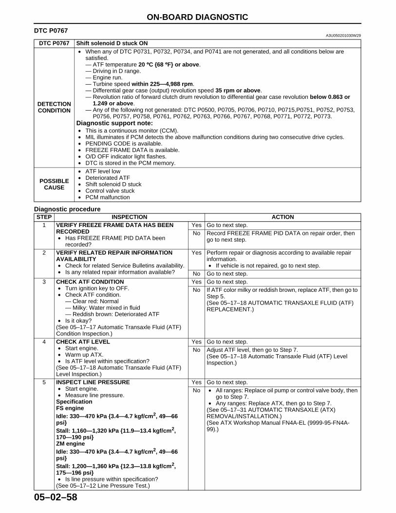
ON-BOARD DIAGNOSTIC
05–02–58
DTC P0767A3U050201030W29
Diagnostic procedure
DTC P0767 Shift solenoid D stuck ON
DETECTION CONDITION
• When any of DTC P0731, P0732, P0734, and P0741 are not generated, and all conditions below are satisfied.— ATF temperature 20 °°°°C {68 °°°°F} or above.— Driving in D range.— Engine run.— Turbine speed within 225—4,988 rpm.— Differential gear case (output) revolution speed 35 rpm or above.— Revolution ratio of forward clutch drum revolution to differential gear case revolution below 0.863 or
1.249 or above.— Any of the following not generated: DTC P0500, P0705, P0706, P0710, P0715,P0751, P0752, P0753,
P0756, P0757, P0758, P0761, P0762, P0763, P0766, P0767, P0768, P0771, P0772, P0773.Diagnostic support note:• This is a continuous monitor (CCM).• MIL illuminates if PCM detects the above malfunction conditions during two consecutive drive cycles.• PENDING CODE is available.• FREEZE FRAME DATA is available.• O/D OFF indicator light flashes.• DTC is stored in the PCM memory.
POSSIBLE CAUSE
• ATF level low• Deteriorated ATF• Shift solenoid D stuck• Control valve stuck• PCM malfunction
STEP INSPECTION ACTION1 VERIFY FREEZE FRAME DATA HAS BEEN
RECORDED• Has FREEZE FRAME PID DATA been
recorded?
Yes Go to next step.No Record FREEZE FRAME PID DATA on repair order, then
go to next step.
2 VERIFY RELATED REPAIR INFORMATION AVAILABILITY• Check for related Service Bulletins availability.• Is any related repair information available?
Yes Perform repair or diagnosis according to available repair information.• If vehicle is not repaired, go to next step.
No Go to next step.3 CHECK ATF CONDITION
• Turn ignition key to OFF.• Check ATF condition.
— Clear red: Normal— Milky: Water mixed in fluid— Reddish brown: Deteriorated ATF
• Is it okay?(See 05–17–17 Automatic Transaxle Fluid (ATF) Condition Inspection.)
Yes Go to next step.No If ATF color milky or reddish brown, replace ATF, then go to
Step 5.(See 05–17–18 AUTOMATIC TRANSAXLE FLUID (ATF) REPLACEMENT.)
4 CHECK ATF LEVEL• Start engine.• Warm up ATX.• Is ATF level within specification?
(See 05–17–18 Automatic Transaxle Fluid (ATF) Level Inspection.)
Yes Go to next step.No Adjust ATF level, then go to Step 7.
(See 05–17–18 Automatic Transaxle Fluid (ATF) Level Inspection.)
5 INSPECT LINE PRESSURE• Start engine.• Measure line pressure.
SpecificationFS engineIdle: 330—470 kPa {3.4—4.7 kgf/cm2, 49—66 psi}Stall: 1,160—1,320 kPa {11.9—13.4 kgf/cm2, 170—190 psi}ZM engineIdle: 330—470 kPa {3.4—4.7 kgf/cm2, 49—66 psi}Stall: 1,200—1,360 kPa {12.3—13.8 kgf/cm2, 175—196 psi}• Is line pressure within specification?
(See 05–17–12 Line Pressure Test.)
Yes Go to next step.No • All ranges: Replace oil pump or control valve body, then
go to Step 7.• Any ranges: Replace ATX, then go to Step 7.
(See 05–17–31 AUTOMATIC TRANSAXLE (ATX) REMOVAL/INSTALLATION.)(See ATX Workshop Manual FN4A-EL (9999-95-FN4A-99).)
1712-1U-01G(05-02).fm 58 ページ 2001年6月29日 金曜日 午後4時35分
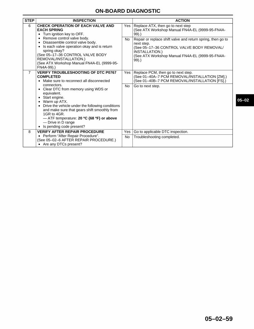
ON-BOARD DIAGNOSTIC
05–02–59
05–02
End Of Sie
6 CHECK OPERATION OF EACH VALVE AND EACH SPRING• Turn ignition key to OFF.• Remove control valve body.• Disassemble control valve body.• Is each valve operation okay and is return
spring okay?(See 05–17–36 CONTROL VALVE BODY REMOVAL/INSTALLATION.)(See ATX Workshop Manual FN4A-EL (9999-95-FN4A-99).)
Yes Replace ATX, then go to next step(See ATX Workshop Manual FN4A-EL (9999-95-FN4A-99).)
No Repair or replace shift valve and return spring, then go to next step.(See 05–17–36 CONTROL VALVE BODY REMOVAL/INSTALLATION.)(See ATX Workshop Manual FN4A-EL (9999-95-FN4A-99).)
7 VERIFY TROUBLESHOOTING OF DTC P0767 COMPLETED• Make sure to reconnect all disconnected
connectors.• Clear DTC from memory using WDS or
equivalent.• Start engine.• Warm up ATX.• Drive the vehicle under the following conditions
and make sure that gears shift smoothly from 1GR to 4GR.— ATF temperature: 20 °°°°C {68 °°°°F} or above— Drive in D range
• Is pending code present?
Yes Replace PCM, then go to next step.(See 01–40A–7 PCM REMOVAL/INSTALLATION [ZM].)(See 01–40B–7 PCM REMOVAL/INSTALLATION [FS].)
No Go to next step.
8 VERIFY AFTER REPAIR PROCEDURE• Perform “After Repair Procedure”.
(See 05–02–6 AFTER REPAIR PROCEDURE.)• Are any DTCs present?
Yes Go to applicable DTC inspection.No Troubleshooting completed.
STEP INSPECTION ACTION
1712-1U-01G(05-02).fm 59 ページ 2001年6月29日 金曜日 午後4時35分
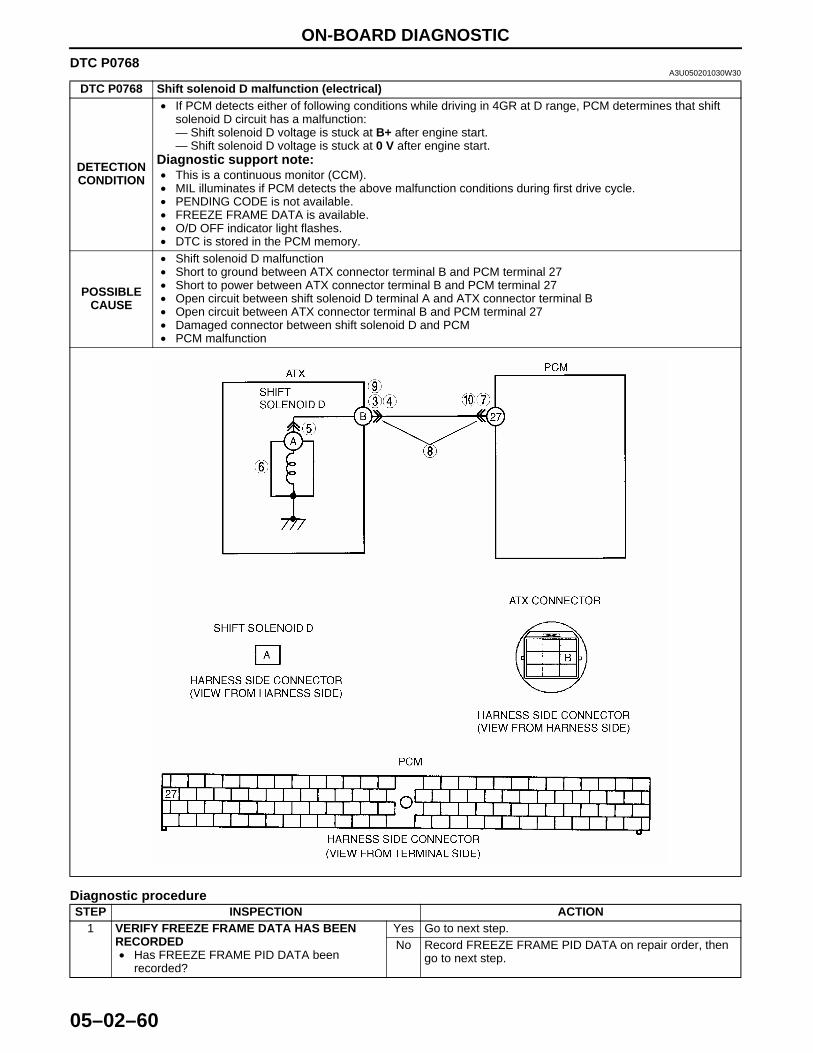
ON-BOARD DIAGNOSTIC
05–02–60
DTC P0768A3U050201030W30
Diagnostic procedure
DTC P0768 Shift solenoid D malfunction (electrical)
DETECTION CONDITION
• If PCM detects either of following conditions while driving in 4GR at D range, PCM determines that shift solenoid D circuit has a malfunction:— Shift solenoid D voltage is stuck at B+ after engine start.— Shift solenoid D voltage is stuck at 0 V after engine start.
Diagnostic support note:• This is a continuous monitor (CCM).• MIL illuminates if PCM detects the above malfunction conditions during first drive cycle.• PENDING CODE is not available.• FREEZE FRAME DATA is available.• O/D OFF indicator light flashes.• DTC is stored in the PCM memory.
POSSIBLE CAUSE
• Shift solenoid D malfunction• Short to ground between ATX connector terminal B and PCM terminal 27• Short to power between ATX connector terminal B and PCM terminal 27• Open circuit between shift solenoid D terminal A and ATX connector terminal B• Open circuit between ATX connector terminal B and PCM terminal 27• Damaged connector between shift solenoid D and PCM• PCM malfunction
STEP INSPECTION ACTION1 VERIFY FREEZE FRAME DATA HAS BEEN
RECORDED• Has FREEZE FRAME PID DATA been
recorded?
Yes Go to next step.No Record FREEZE FRAME PID DATA on repair order, then
go to next step.
1712-1U-01G(05-02).fm 60 ページ 2001年6月29日 金曜日 午後4時35分

ON-BOARD DIAGNOSTIC
05–02–61
05–02
2 VERIFY RELATED REPAIR INFORMATION AVAILABILITY• Check for related Service Bulletins availability.• Is any related repair information available?
Yes Perform repair or diagnosis according to available repair information.• If vehicle is not repaired, go to next step.
No Go to next step.3 INSPECT ATX CONNECTOR FOR POOR
CONNECTION• Turn ignition key to OFF.• Disconnect ATX connector.• Check for poor connection (damaged/pulled-
out terminals, corrosion, etc.).• Is connection okay?
Yes Go to next step.No Repair or replace connector and/or terminals, then go to
Step 11.
4 INSPECT RESISTANCE• Inspect resistance between ATX connector
terminal B (transaxle case side) and body ground.
• Is resistance within 10.9—26.2 ohms?(See 05–17–28 Inspection of Resistance (On-vehicle).)
Yes Go to Step 7.No Go to next step.
5 INSPECT SHIFT SOLENOID D CONNECTOR FOR POOR CONNECTION• Disconnect shift solenoid D connector.• Check for poor connection (damaged/pulled-
out terminals, corrosion, etc.).• Is connection okay?
Yes Go to next step.No Repair or replace connector and/or terminal, then go to
Step 11.
6 INSPECT RESISTANCE• inspect resistance between shift solenoid D
terminal A (part-side) and body ground.• Is resistance within 10.9—26.2 ohms?
(See 05–17–29 Resistance Inspection (Off-vehicle).)
Yes Replace solenoid harness, then go to Step 11.No Verify shift solenoid D installation.
• If solenoid installed correctly, replace solenoid, then go to Step 11.
(See 05–17–30 SOLENOID VALVES REMOVAL/INSTALLATION.)
7 INSPECT PCM CONNECTOR FOR POOR CONNECTION• Disconnect PCM connector.• Check for poor connection (damaged/pulled-
out terminals, corrosion, etc.).• Is connection okay?
Yes Go to next step.No Repair or replace connector and/or terminals, then go to
Step 11.
8 INSPECT ATX CONNECTOR CIRCUIT FOR OPEN• Inspect for continuity between PCM terminal 27
(harness-side) and ATX connector terminal B (vehicle harness-side).
• Is there continuity between terminals?
Yes Go to next step.No Repair or replace harness, then go to Step 11.
9 INSPECT ATX CONNECTOR CIRCUIT FOR SHORT TO POWER• Turn ignition key to ON (engine OFF).• Inspect voltage at ATX connector terminal B
(vehicle harness-side).• Is voltage 0 V?
Yes Go to next step.No Repair or replace harness, then go to Step 11.
10 INSPECT PCM CIRCUIT FOR SHORT TO GROUND• Turn ignition key to OFF.• Inspect continuity between PCM terminal 27
(harness-side) and body ground.• Is there continuity?
Yes Repair or replace harness, then go to Step 11.No Go to next step.
11 VERIFY TROUBLESHOOTING OF DTC P0768 COMPLETED• Make sure to reconnect all disconnected
connectors.• Clear DTC from memory using WDS or
equivalent.• Drive vehicle in D range and make sure that
gears shift smoothly from 1GR to 4GR.• Are any DTCs present?
Yes Replace PCM, then go to next step.(See 01–40A–7 PCM REMOVAL/INSTALLATION [ZM].)(See 01–40B–7 PCM REMOVAL/INSTALLATION [FS].)
No No concern is detected. Go to next step.
12 VERIFY AFTER REPAIR PROCEDURE• Perform “After Repair Procedure”.
(See 05–02–6 AFTER REPAIR PROCEDURE.)• Are any DTCs present?
Yes Go to applicable DTC inspection.No Troubleshooting completed.
STEP INSPECTION ACTION
1712-1U-01G(05-02).fm 61 ページ 2001年6月29日 金曜日 午後4時35分
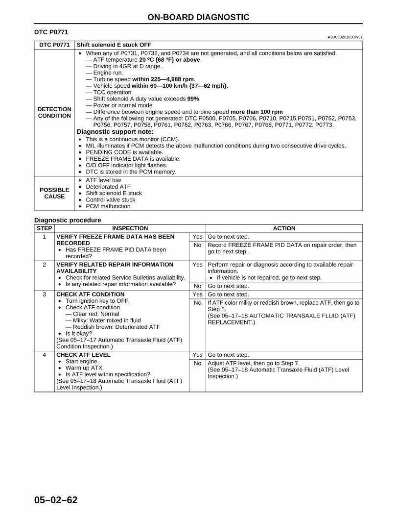
ON-BOARD DIAGNOSTIC
05–02–62
End Of Sie
DTC P0771A3U050201030W31
Diagnostic procedure
DTC P0771 Shift solenoid E stuck OFF
DETECTION CONDITION
• When any of P0731, P0732, and P0734 are not generated, and all conditions below are satisfied.— ATF temperature 20 °°°°C {68 °°°°F} or above.— Driving in 4GR at D range.— Engine run.— Turbine speed within 225—4,988 rpm.— Vehicle speed within 60—100 km/h {37—62 mph}.— TCC operation— Shift solenoid A duty value exceeds 99%— Power or normal mode— Difference between engine speed and turbine speed more than 100 rpm— Any of the following not generated: DTC P0500, P0705, P0706, P0710, P0715,P0751, P0752, P0753,
P0756, P0757, P0758, P0761, P0762, P0763, P0766, P0767, P0768, P0771, P0772, P0773.Diagnostic support note:• This is a continuous monitor (CCM).• MIL illuminates if PCM detects the above malfunction conditions during two consecutive drive cycles.• PENDING CODE is available.• FREEZE FRAME DATA is available.• O/D OFF indicator light flashes.• DTC is stored in the PCM memory.
POSSIBLE CAUSE
• ATF level low• Deteriorated ATF• Shift solenoid E stuck• Control valve stuck• PCM malfunction
STEP INSPECTION ACTION1 VERIFY FREEZE FRAME DATA HAS BEEN
RECORDED• Has FREEZE FRAME PID DATA been
recorded?
Yes Go to next step.No Record FREEZE FRAME PID DATA on repair order, then
go to next step.
2 VERIFY RELATED REPAIR INFORMATION AVAILABILITY• Check for related Service Bulletins availability.• Is any related repair information available?
Yes Perform repair or diagnosis according to available repair information.• If vehicle is not repaired, go to next step.
No Go to next step.3 CHECK ATF CONDITION
• Turn ignition key to OFF.• Check ATF condition.
— Clear red: Normal— Milky: Water mixed in fluid— Reddish brown: Deteriorated ATF
• Is it okay?(See 05–17–17 Automatic Transaxle Fluid (ATF) Condition Inspection.)
Yes Go to next step.No If ATF color milky or reddish brown, replace ATF, then go to
Step 5.(See 05–17–18 AUTOMATIC TRANSAXLE FLUID (ATF) REPLACEMENT.)
4 CHECK ATF LEVEL• Start engine.• Warm up ATX.• Is ATF level within specification?
(See 05–17–18 Automatic Transaxle Fluid (ATF) Level Inspection.)
Yes Go to next step.No Adjust ATF level, then go to Step 7.
(See 05–17–18 Automatic Transaxle Fluid (ATF) Level Inspection.)
1712-1U-01G(05-02).fm 62 ページ 2001年6月29日 金曜日 午後4時35分

ON-BOARD DIAGNOSTIC
05–02–63
05–02
End Of Sie
5 INSPECT LINE PRESSURE• Start engine.• Measure line pressure.
SpecificationFS engineIdle: 330—470 kPa {3.4—4.7 kgf/cm2, 49—66 psi}Stall: 1,160—1,320 kPa {11.9—13.4 kgf/cm2, 170—190 psi}ZM engineIdle: 330—470 kPa {3.4—4.7 kgf/cm2, 49—66 psi}Stall: 1,200—1,360 kPa {12.3—13.8 kgf/cm2, 175—196 psi}• Is line pressure within specification?
(See 05–17–12 Line Pressure Test.)
Yes Go to next step.No • All ranges: Replace oil pump or control valve body, then
go to Step 7.• Any ranges: Replace ATX, then go to Step 7.
(See 05–17–31 AUTOMATIC TRANSAXLE (ATX) REMOVAL/INSTALLATION.)(See ATX Workshop Manual FN4A-EL (9999-95-FN4A-99).)
6 CHECK OPERATION OF EACH VALVE AND EACH SPRING• Turn ignition key to OFF.• Remove control valve body.• Disassemble control valve body.• Is each valve operation okay and is return
spring okay?(See 05–17–36 CONTROL VALVE BODY REMOVAL/INSTALLATION.)(See ATX Workshop Manual FN4A-EL (9999-95-FN4A-99).)
Yes Replace ATX, then go to next step(See ATX Workshop Manual FN4A-EL (9999-95-FN4A-99).)
No Repair or replace shift valve and return spring, then go to next step.(See 05–17–36 CONTROL VALVE BODY REMOVAL/INSTALLATION.)(See ATX Workshop Manual FN4A-EL (9999-95-FN4A-99).)
7 VERIFY TROUBLESHOOTING OF DTC P0771 COMPLETED• Make sure to reconnect all disconnected
connectors.• Clear DTC from memory using WDS or
equivalent.• Start engine.• Warm up ATX.• Drive the vehicle under the following conditions
and make sure that gears shift smoothly from 1GR to 4GR.— ATF temperature: 20 °°°°C {68 °°°°F} or above— Drive in D range— Vehicle speed: within 60—100 km/h {37—
62 mph} (4th gear only).• Is pending code present?
Yes Replace PCM, then go to next step.(See 01–40A–7 PCM REMOVAL/INSTALLATION [ZM].)(See 01–40B–7 PCM REMOVAL/INSTALLATION [FS].)
No Go to next step.
8 VERIFY AFTER REPAIR PROCEDURE• Perform “After Repair Procedure”.
(See 05–02–6 AFTER REPAIR PROCEDURE.)• Are any DTCs present?
Yes Go to applicable DTC inspection.No Troubleshooting completed.
STEP INSPECTION ACTION
1712-1U-01G(05-02).fm 63 ページ 2001年6月29日 金曜日 午後4時35分
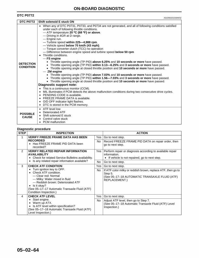
ON-BOARD DIAGNOSTIC
05–02–64
DTC P0772A3U050201030W32
Diagnostic procedure
DTC P0772 Shift solenoid E stuck ON
DETECTION CONDITION
• When any of DTC P0731, P0733, and P0734 are not generated, and all of following conditions satisfied under each of following throttle conditions.— ATF temperature 20 °°°°C {68 °°°°F} or above.— Driving in 4GR at D range.— Engine run.— Turbine speed within 225—4,988 rpm.— Vehicle speed below 70 km/h {43 mph}.— Torque converter clutch (TCC) no operation— Difference between engine speed and turbine speed below 50 rpm
• Throttle conditions.— FS engine
• Throttle opening angle (TP PID) above 6.25% and 10 seconds or more have passed.• Throttle opening angle (TP PID) within 3.13—6.25% and 3 seconds or more have passed.• Throttle opening angle at closed throttle position and 10 seconds or more have passed.
— ZM engine• Throttle opening angle (TP PID) above 7.03% and 10 seconds or more have passed.• Throttle opening angle (TP PID) within 1.56—7.03% and 3 seconds or more have passed.• Throttle opening angle at closed throttle position and 10 seconds or more have passed.
Diagnostic support note:• This is a continuous monitor (CCM).• MIL illuminates if PCM detects the above malfunction conditions during two consecutive drive cycles.• PENDING CODE is available.• FREEZE FRAME DATA is available.• O/D OFF indicator light flashes.• DTC is stored in the PCM memory.
POSSIBLE CAUSE
• ATF level low• Deteriorated ATF• Shift solenoid E stuck• Control valve stuck• PCM malfunction
STEP INSPECTION ACTION1 VERIFY FREEZE FRAME DATA HAS BEEN
RECORDED• Has FREEZE FRAME PID DATA been
recorded?
Yes Go to next step.No Record FREEZE FRAME PID DATA on repair order, then
go to next step.
2 VERIFY RELATED REPAIR INFORMATION AVAILABILITY• Check for related Service Bulletins availability.• Is any related repair information available?
Yes Perform repair or diagnosis according to available repair information.• If vehicle is not repaired, go to next step.
No Go to next step.3 CHECK ATF CONDITION
• Turn ignition key to OFF.• Check ATF condition.
— Clear red: Normal— Milky: Water mixed in fluid— Reddish brown: Deteriorated ATF
• Is it okay?(See 05–17–17 Automatic Transaxle Fluid (ATF) Condition Inspection.)
Yes Go to next step.No If ATF color milky or reddish brown, replace ATF, then go to
Step 5.(See 05–17–18 AUTOMATIC TRANSAXLE FLUID (ATF) REPLACEMENT.)
4 CHECK ATF LEVEL• Start engine.• Warm up ATX.• Is ATF level within specification?
(See 05–17–18 Automatic Transaxle Fluid (ATF) Level Inspection.)
Yes Go to next step.No Adjust ATF level, then go to Step 7.
(See 05–17–18 Automatic Transaxle Fluid (ATF) Level Inspection.)
1712-1U-01G(05-02).fm 64 ページ 2001年6月29日 金曜日 午後4時35分
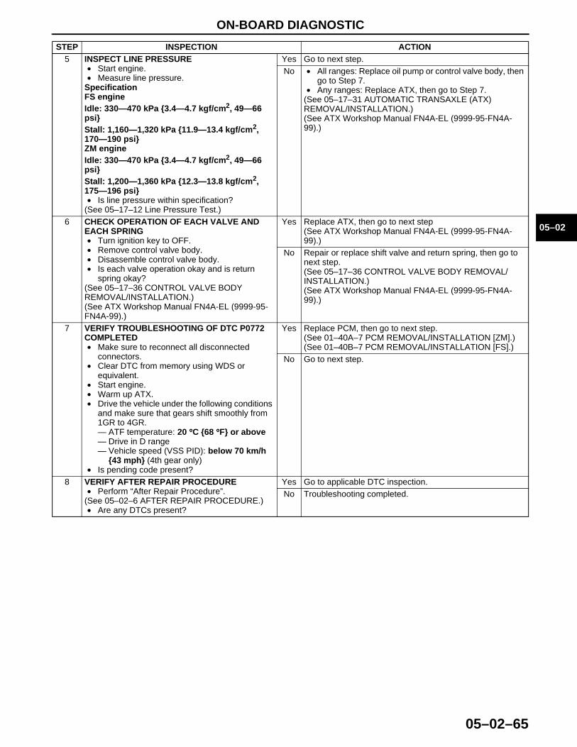
ON-BOARD DIAGNOSTIC
05–02–65
05–02
End Of Sie
5 INSPECT LINE PRESSURE• Start engine.• Measure line pressure.
SpecificationFS engineIdle: 330—470 kPa {3.4—4.7 kgf/cm2, 49—66 psi}Stall: 1,160—1,320 kPa {11.9—13.4 kgf/cm2, 170—190 psi}ZM engineIdle: 330—470 kPa {3.4—4.7 kgf/cm2, 49—66 psi}Stall: 1,200—1,360 kPa {12.3—13.8 kgf/cm2, 175—196 psi}• Is line pressure within specification?
(See 05–17–12 Line Pressure Test.)
Yes Go to next step.No • All ranges: Replace oil pump or control valve body, then
go to Step 7.• Any ranges: Replace ATX, then go to Step 7.
(See 05–17–31 AUTOMATIC TRANSAXLE (ATX) REMOVAL/INSTALLATION.)(See ATX Workshop Manual FN4A-EL (9999-95-FN4A-99).)
6 CHECK OPERATION OF EACH VALVE AND EACH SPRING• Turn ignition key to OFF.• Remove control valve body.• Disassemble control valve body.• Is each valve operation okay and is return
spring okay?(See 05–17–36 CONTROL VALVE BODY REMOVAL/INSTALLATION.)(See ATX Workshop Manual FN4A-EL (9999-95-FN4A-99).)
Yes Replace ATX, then go to next step(See ATX Workshop Manual FN4A-EL (9999-95-FN4A-99).)
No Repair or replace shift valve and return spring, then go to next step.(See 05–17–36 CONTROL VALVE BODY REMOVAL/INSTALLATION.)(See ATX Workshop Manual FN4A-EL (9999-95-FN4A-99).)
7 VERIFY TROUBLESHOOTING OF DTC P0772 COMPLETED• Make sure to reconnect all disconnected
connectors.• Clear DTC from memory using WDS or
equivalent.• Start engine.• Warm up ATX.• Drive the vehicle under the following conditions
and make sure that gears shift smoothly from 1GR to 4GR.— ATF temperature: 20 °°°°C {68 °°°°F} or above— Drive in D range— Vehicle speed (VSS PID): below 70 km/h
{43 mph} (4th gear only)• Is pending code present?
Yes Replace PCM, then go to next step.(See 01–40A–7 PCM REMOVAL/INSTALLATION [ZM].)(See 01–40B–7 PCM REMOVAL/INSTALLATION [FS].)
No Go to next step.
8 VERIFY AFTER REPAIR PROCEDURE• Perform “After Repair Procedure”.
(See 05–02–6 AFTER REPAIR PROCEDURE.)• Are any DTCs present?
Yes Go to applicable DTC inspection.No Troubleshooting completed.
STEP INSPECTION ACTION
1712-1U-01G(05-02).fm 65 ページ 2001年6月29日 金曜日 午後4時35分
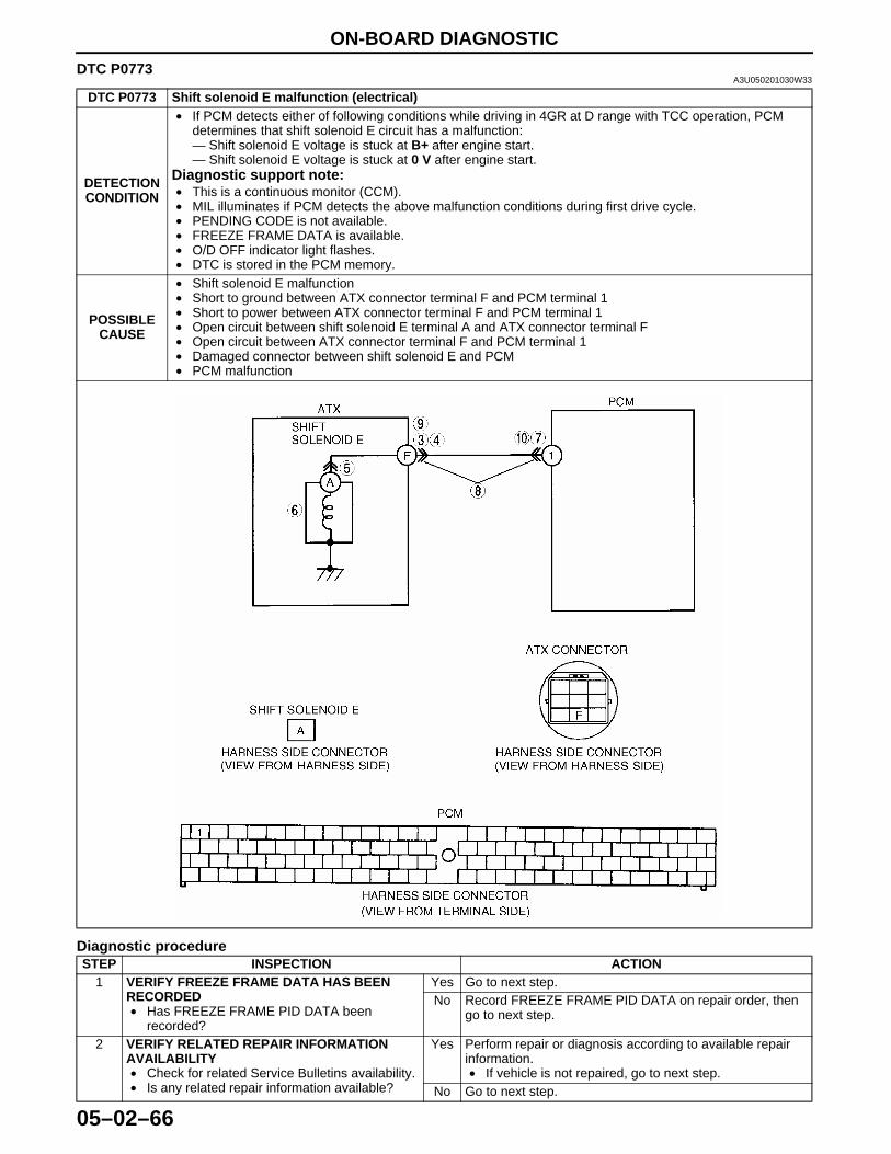
ON-BOARD DIAGNOSTIC
05–02–66
DTC P0773A3U050201030W33
Diagnostic procedure
DTC P0773 Shift solenoid E malfunction (electrical)
DETECTION CONDITION
• If PCM detects either of following conditions while driving in 4GR at D range with TCC operation, PCM determines that shift solenoid E circuit has a malfunction:— Shift solenoid E voltage is stuck at B+ after engine start.— Shift solenoid E voltage is stuck at 0 V after engine start.
Diagnostic support note:• This is a continuous monitor (CCM).• MIL illuminates if PCM detects the above malfunction conditions during first drive cycle.• PENDING CODE is not available.• FREEZE FRAME DATA is available.• O/D OFF indicator light flashes.• DTC is stored in the PCM memory.
POSSIBLE CAUSE
• Shift solenoid E malfunction• Short to ground between ATX connector terminal F and PCM terminal 1• Short to power between ATX connector terminal F and PCM terminal 1• Open circuit between shift solenoid E terminal A and ATX connector terminal F• Open circuit between ATX connector terminal F and PCM terminal 1• Damaged connector between shift solenoid E and PCM• PCM malfunction
STEP INSPECTION ACTION1 VERIFY FREEZE FRAME DATA HAS BEEN
RECORDED• Has FREEZE FRAME PID DATA been
recorded?
Yes Go to next step.No Record FREEZE FRAME PID DATA on repair order, then
go to next step.
2 VERIFY RELATED REPAIR INFORMATION AVAILABILITY• Check for related Service Bulletins availability.• Is any related repair information available?
Yes Perform repair or diagnosis according to available repair information.• If vehicle is not repaired, go to next step.
No Go to next step.
1712-1U-01G(05-02).fm 66 ページ 2001年6月29日 金曜日 午後4時35分
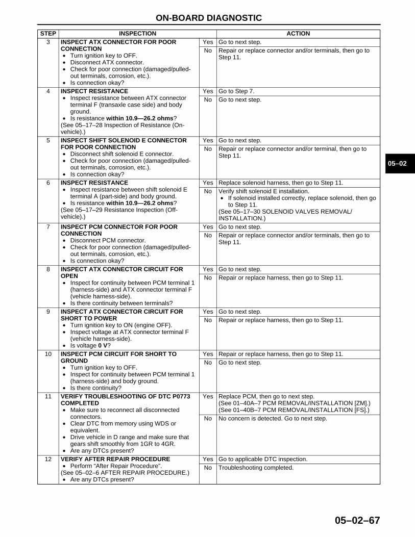
ON-BOARD DIAGNOSTIC
05–02–67
05–02
End Of Sie
3 INSPECT ATX CONNECTOR FOR POOR CONNECTION• Turn ignition key to OFF.• Disconnect ATX connector.• Check for poor connection (damaged/pulled-
out terminals, corrosion, etc.).• Is connection okay?
Yes Go to next step.No Repair or replace connector and/or terminals, then go to
Step 11.
4 INSPECT RESISTANCE• Inspect resistance between ATX connector
terminal F (transaxle case side) and body ground.
• Is resistance within 10.9—26.2 ohms?(See 05–17–28 Inspection of Resistance (On-vehicle).)
Yes Go to Step 7.No Go to next step.
5 INSPECT SHIFT SOLENOID E CONNECTOR FOR POOR CONNECTION• Disconnect shift solenoid E connector.• Check for poor connection (damaged/pulled-
out terminals, corrosion, etc.).• Is connection okay?
Yes Go to next step.No Repair or replace connector and/or terminal, then go to
Step 11.
6 INSPECT RESISTANCE• Inspect resistance between shift solenoid E
terminal A (part-side) and body ground.• Is resistance within 10.9—26.2 ohms?
(See 05–17–29 Resistance Inspection (Off-vehicle).)
Yes Replace solenoid harness, then go to Step 11.No Verify shift solenoid E installation.
• If solenoid installed correctly, replace solenoid, then go to Step 11.
(See 05–17–30 SOLENOID VALVES REMOVAL/INSTALLATION.)
7 INSPECT PCM CONNECTOR FOR POOR CONNECTION• Disconnect PCM connector.• Check for poor connection (damaged/pulled-
out terminals, corrosion, etc.).• Is connection okay?
Yes Go to next step.No Repair or replace connector and/or terminals, then go to
Step 11.
8 INSPECT ATX CONNECTOR CIRCUIT FOR OPEN• Inspect for continuity between PCM terminal 1
(harness-side) and ATX connector terminal F (vehicle harness-side).
• Is there continuity between terminals?
Yes Go to next step.No Repair or replace harness, then go to Step 11.
9 INSPECT ATX CONNECTOR CIRCUIT FOR SHORT TO POWER• Turn ignition key to ON (engine OFF).• Inspect voltage at ATX connector terminal F
(vehicle harness-side).• Is voltage 0 V?
Yes Go to next step.No Repair or replace harness, then go to Step 11.
10 INSPECT PCM CIRCUIT FOR SHORT TO GROUND• Turn ignition key to OFF.• Inspect for continuity between PCM terminal 1
(harness-side) and body ground.• Is there continuity?
Yes Repair or replace harness, then go to Step 11.No Go to next step.
11 VERIFY TROUBLESHOOTING OF DTC P0773 COMPLETED• Make sure to reconnect all disconnected
connectors.• Clear DTC from memory using WDS or
equivalent.• Drive vehicle in D range and make sure that
gears shift smoothly from 1GR to 4GR.• Are any DTCs present?
Yes Replace PCM, then go to next step.(See 01–40A–7 PCM REMOVAL/INSTALLATION [ZM].)(See 01–40B–7 PCM REMOVAL/INSTALLATION [FS].)
No No concern is detected. Go to next step.
12 VERIFY AFTER REPAIR PROCEDURE• Perform “After Repair Procedure”.
(See 05–02–6 AFTER REPAIR PROCEDURE.)• Are any DTCs present?
Yes Go to applicable DTC inspection.No Troubleshooting completed.
STEP INSPECTION ACTION
1712-1U-01G(05-02).fm 67 ページ 2001年6月29日 金曜日 午後4時35分
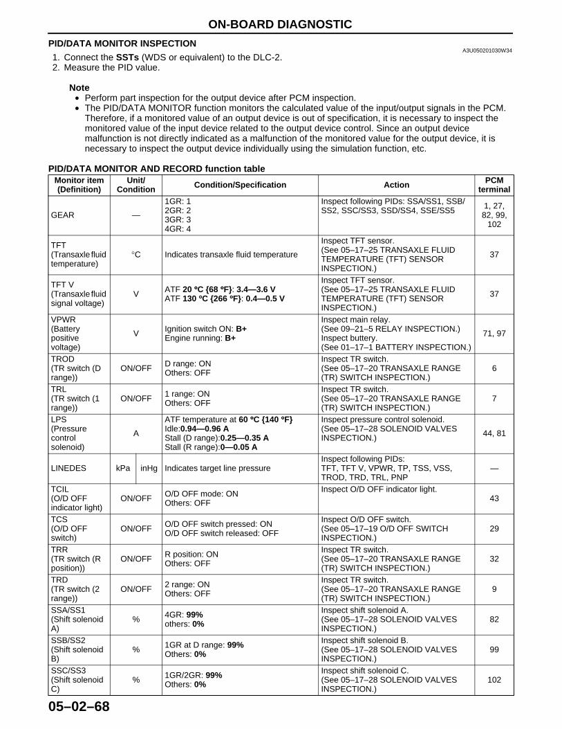
ON-BOARD DIAGNOSTIC
05–02–68
PID/DATA MONITOR INSPECTIONA3U050201030W34
1. Connect the SSTs (WDS or equivalent) to the DLC-2.2. Measure the PID value.
Note• Perform part inspection for the output device after PCM inspection.• The PID/DATA MONITOR function monitors the calculated value of the input/output signals in the PCM.
Therefore, if a monitored value of an output device is out of specification, it is necessary to inspect the monitored value of the input device related to the output device control. Since an output device malfunction is not directly indicated as a malfunction of the monitored value for the output device, it is necessary to inspect the output device individually using the simulation function, etc.
PID/DATA MONITOR AND RECORD function tableMonitor item (Definition)
Unit/Condition Condition/Specification Action PCM
terminal
GEAR —
1GR: 12GR: 23GR: 34GR: 4
Inspect following PIDs: SSA/SS1, SSB/SS2, SSC/SS3, SSD/SS4, SSE/SS5 1, 27,
82, 99, 102
TFT(Transaxle fluid temperature)
°C Indicates transaxle fluid temperature
Inspect TFT sensor.(See 05–17–25 TRANSAXLE FLUID TEMPERATURE (TFT) SENSOR INSPECTION.)
37
TFT V(Transaxle fluid signal voltage)
V ATF 20 °°°°C {68 °°°°F}: 3.4—3.6 VATF 130 °°°°C {266 °°°°F}: 0.4—0.5 V
Inspect TFT sensor.(See 05–17–25 TRANSAXLE FLUID TEMPERATURE (TFT) SENSOR INSPECTION.)
37
VPWR(Battery positive voltage)
V Ignition switch ON: B+Engine running: B+
Inspect main relay.(See 09–21–5 RELAY INSPECTION.)Inspect buttery.(See 01–17–1 BATTERY INSPECTION.)
71, 97
TROD(TR switch (D range))
ON/OFF D range: ONOthers: OFF
Inspect TR switch.(See 05–17–20 TRANSAXLE RANGE (TR) SWITCH INSPECTION.)
6
TRL(TR switch (1 range))
ON/OFF 1 range: ONOthers: OFF
Inspect TR switch.(See 05–17–20 TRANSAXLE RANGE (TR) SWITCH INSPECTION.)
7
LPS(Pressure control solenoid)
A
ATF temperature at 60 °°°°C {140 °°°°F}Idle:0.94—0.96 AStall (D range):0.25—0.35 AStall (R range):0—0.05 A
Inspect pressure control solenoid.(See 05–17–28 SOLENOID VALVES INSPECTION.) 44, 81
LINEDES kPa inHg Indicates target line pressureInspect following PIDs:TFT, TFT V, VPWR, TP, TSS, VSS, TROD, TRD, TRL, PNP
—
TCIL(O/D OFF indicator light)
ON/OFF O/D OFF mode: ONOthers: OFF
Inspect O/D OFF indicator light.43
TCS(O/D OFF switch)
ON/OFF O/D OFF switch pressed: ONO/D OFF switch released: OFF
Inspect O/D OFF switch.(See 05–17–19 O/D OFF SWITCH INSPECTION.)
29
TRR(TR switch (R position))
ON/OFF R position: ONOthers: OFF
Inspect TR switch.(See 05–17–20 TRANSAXLE RANGE (TR) SWITCH INSPECTION.)
32
TRD(TR switch (2 range))
ON/OFF 2 range: ONOthers: OFF
Inspect TR switch.(See 05–17–20 TRANSAXLE RANGE (TR) SWITCH INSPECTION.)
9
SSA/SS1(Shift solenoid A)
% 4GR: 99%others: 0%
Inspect shift solenoid A.(See 05–17–28 SOLENOID VALVES INSPECTION.)
82
SSB/SS2(Shift solenoid B)
% 1GR at D range: 99%Others: 0%
Inspect shift solenoid B.(See 05–17–28 SOLENOID VALVES INSPECTION.)
99
SSC/SS3(Shift solenoid C)
% 1GR/2GR: 99%Others: 0%
Inspect shift solenoid C.(See 05–17–28 SOLENOID VALVES INSPECTION.)
102
1712-1U-01G(05-02).fm 68 ページ 2001年6月29日 金曜日 午後4時35分
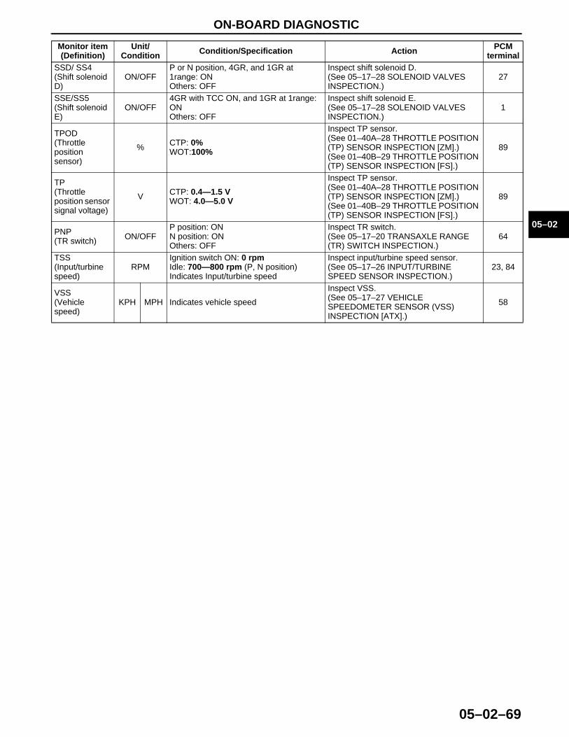
ON-BOARD DIAGNOSTIC
05–02–69
05–02
End Of Sie
SSD/ SS4(Shift solenoid D)
ON/OFFP or N position, 4GR, and 1GR at 1range: ONOthers: OFF
Inspect shift solenoid D.(See 05–17–28 SOLENOID VALVES INSPECTION.)
27
SSE/SS5(Shift solenoid E)
ON/OFF4GR with TCC ON, and 1GR at 1range: ONOthers: OFF
Inspect shift solenoid E.(See 05–17–28 SOLENOID VALVES INSPECTION.)
1
TPOD(Throttle positionsensor)
% CTP: 0%WOT:100%
Inspect TP sensor.(See 01–40A–28 THROTTLE POSITION (TP) SENSOR INSPECTION [ZM].)(See 01–40B–29 THROTTLE POSITION (TP) SENSOR INSPECTION [FS].)
89
TP(Throttle position sensor signal voltage)
V CTP: 0.4—1.5 VWOT: 4.0—5.0 V
Inspect TP sensor.(See 01–40A–28 THROTTLE POSITION (TP) SENSOR INSPECTION [ZM].)(See 01–40B–29 THROTTLE POSITION (TP) SENSOR INSPECTION [FS].)
89
PNP(TR switch) ON/OFF
P position: ONN position: ONOthers: OFF
Inspect TR switch.(See 05–17–20 TRANSAXLE RANGE (TR) SWITCH INSPECTION.)
64
TSS(Input/turbine speed)
RPMIgnition switch ON: 0 rpmIdle: 700—800 rpm (P, N position)Indicates Input/turbine speed
Inspect input/turbine speed sensor.(See 05–17–26 INPUT/TURBINE SPEED SENSOR INSPECTION.)
23, 84
VSS(Vehicle speed)
KPH MPH Indicates vehicle speed
Inspect VSS.(See 05–17–27 VEHICLE SPEEDOMETER SENSOR (VSS) INSPECTION [ATX].)
58
Monitor item (Definition)
Unit/Condition Condition/Specification Action PCM
terminal
1712-1U-01G(05-02).fm 69 ページ 2001年6月29日 金曜日 午後4時35分