TRANSMISSION SYSTEM SECURITY AND … SYSTEM SECURITY AND PLANNING STANDARDS (TSSPS) ... equipment...
16
TRANSMISSION SYSTEM SECURITY AND PLANNING STANDARDS (TSSPS) May 2016
Transcript of TRANSMISSION SYSTEM SECURITY AND … SYSTEM SECURITY AND PLANNING STANDARDS (TSSPS) ... equipment...
TRANSMISSION SYSTEM SECURITY
AND PLANNING STANDARDS
(TSSPS)
May 2016

TSSPS • May 2016
Page 2
1 General Principles
The specific function of transmission planning is to ensure the co-ordinated development of a reliable, efficient, and economical system for the transmission of electricity for the long-term benefit of transmission users. The planning process involves the application of technical reliability criteria, economics, consideration of transmission operations, maintenance and protection, co-ordination with generation and distribution functions, information technology, strategic considerations and new technologies and environmental aspects.
The Transmission System Security Planning Standards (TSSPS) set out the standards that are applied in the planning time frame. The standards for day-to-day operation of the system are set out in the EirGrid Grid Code and the EirGrid Operating and Security Standards.
1.1 Objective
The primary aim of transmission planning is the maintenance of the integrity of the bulk transmission system. The adequacy and security of supply to any particular load or area is secondary to this primary aim. The technical considerations are continually mitigated by economic considerations and all other factors that various stakeholders in the transmission system would consider significant.
1.2 Reliability Criteria
Reliability criteria are defined and measured in terms of performance of a system under various contingencies. Prediction of performance is based on simulation, rather than actual tests. These criteria are based on the fundamental assumption that system integrity will be maintained for the more probable and less probable contingencies and that there is no loss of load for the common more probable contingencies.
1.3 Overall Assessment
Any transmission plan proposed for adoption under these criteria must ultimately be justifiable taking account of economic, financial, strategic and environmental considerations.
1.4 Planning Horizons
Planning time frames in the near-term (one year ahead) and long-term (more than 20 years ahead) are subject to a limited set of performance tests which at the least includes tests for more probable contingencies.
These planning standards and performance tests are applied to medium-term planning horizons (of the order of two to 15 years) upon which transmission development reports and other relevant planning documents are to be based.
TSSPS • May 2016
Page 3
1.5 Stability Study Definitions
Stability: is the ability of an electric power system, for a given initial operating condition, to regain a state of operating equilibrium after being subjected to a physical disturbance, with most system variables bounded so that practically the entire system remains intact.
Instability: is characterised by the magnitude and duration of power system oscillations. These oscillations could grow so large that a system becomes dynamically unstable.
Transient Stability: is defined as the ability of the power system to maintain synchronism when subjected to severe disturbances.
Frequency Stability: is defined as the ability of a power system to attain a steady frequency following a severe system disturbance.
Small Signal Stability: is defined as the ability of system to maintain synchronism under small disturbances such as operational switching.
Stability Simulation: A generic term for simulations used to examine the stability of the system following disturbances for either, Transient stability, Frequency stability or Small signal stability.
TSSPS • May 2016
Page 4
2 EirGrid Transmission System Security Planning Standards
The system shall be designed to operate within normal operating ranges for credible load and generation patterns for base case operation. The system shall be designed to withstand the more probable contingencies without widespread system failure and instability, maintaining power quality within specified voltage and frequency fluctuation ranges and maintaining voltage and thermal loadings within operating limits. The more probable contingencies are comprised of single contingency (N-1), overlapping single contingency and generator outage (N-G-1) and double outage contingency (N-1-1) disturbances.
In the immediate aftermath of a disturbance, the system should reach a steady state that is within emergency limits. Then, by use of remedial actions specified in the criteria, the system should be capable of being returned to normal limits
The criteria for transmission system contingency performance are established in terms of the results of simulation tests. These are summarised in Table 1. These tests do not preclude further, detailed tests that would enhance planning for specific components of the transmission system. Additional detailed tests may include substation reliability evaluation, voltage collapse simulation, subsynchronous resonance calculations, switching simulations, harmonic resonance, etc.
2.1 Contingencies
2.1.1 More Probable Contingencies
Base Case
For base case operation, i.e. with all items of transmission plant available, the system shall operate within normal limits. This test is performed using steady-state power flows. Transformer tap-changing, reactive power compensation and busbar sectionalising may be utilised as required to provide acceptable base case loadings and voltages. Several base cases may be required to model the necessary range of load levels and generation patterns.
The base cases are used as the starting point for contingency studies.
Stability studies, as described in Table 1, should compare the base case with and without the planned solution.
Single Contingency
The single contingency test N-1 covers the loss of any single item of power infeed or transmission equipment at any time. Since it is plausible that at any time, one of the power infeeds could be off-line, for any number of reasons, an overlapping single contingency and power infeed outage N-G-1 is also investigated.
Where transformer tap-changing, reactive power compensation and busbar sectionalising can be used in the base case to minimise the impact of potential single contingencies, this shall be done. The N-G-1 case may be modified in preparation for the second outage (e.g. following the power infeed outage but before the second
TSSPS • May 2016
Page 5
outage) as follows: tap-changing, reactive power compensation dispatch, power infeed redispatch and busbar sectionalising (see Table 1).
Trip-Maintenance Contingency
The trip-maintenance N-1-1 tests include disturbances in which the trip outage of a transmission or power infeed element occurs while another element is on an outage, where there is sufficient period between the first and second outage to allow for adjustment back to normal operation.
The case may be modified in preparation for the second outage (i.e. following the first outage but before the second trip outage) as follows: tap-changing, power flow controller dispatch, reactive power compensation dispatch, power infeed redispatch and busbar sectionalising.
Although single and trip-maintenance contingencies are both considered probable disturbances, the criteria for trip-maintenance outage events are slightly different, recognising that exposure to these events is much less than single contingency events. In particular, some loss of load is allowed for trip-maintenance outage events and the test is only applied for outage season scenarios.
2.1.2 Less Probable Contingencies
For system integrity, the system should be able to withstand more severe but less probable contingencies. Examples of this class of contingencies are busbar faults, busbar coupler faults, breaker failures, relay maloperation, loss of double circuit, etc. (see Table 1).
Stability simulations are required to be appropriate to the planned solution and would typically include zero impedance three phase bus fault for stations in close proximity to the planned solution and/or loss of generation due to long extended fault duration.
2.2 Contingency Performance Tests
2.2.1 More Probable Contingencies
Base Case
The system shall operate within normal limits.
Single Contingency and Trip-Maintenance Outage Contingency
1. For the transient period, the planned transmission system should be transiently stable with voltage and frequency fluctuations within acceptable limits (see Section 2.3). The dynamic simulations are performed with fast-acting automatic controls such as generator voltage regulators and power system stabilisers (PSS), and static var systems (SVC) etc. Protection and control-based remedial actions, except for those that shed load such as underfrequency and undervoltage relays, are also represented in this simulation.
TSSPS • May 2016
Page 6
Immediately following an outage, the transmission system should not experience Electromagnetic Transient (EMT) Power Frequency temporary overvoltages outside defined limits. Tests are analysed using EMT analysis.
2. Following an outage, the transmission system should not experience voltage collapse or cascading outages. Voltages should be within post-contingency limits and thermal loadings should be within emergency limits. This test is performed using steady-state power flows. The power flow shall include automatic response for voltage regulators, static var systems, speed governors etc. and automatic transfer of disconnected load where appropriate.
3. Within the time for which emergency limits are valid, the system should be able to return to normal limits. This test is performed using steady-state power flows, allowing for control actions such as operator-actuated or automatic tap-changing, capacitor and reactor switching, power flow controllers and power infeed redispatch. Off-line generation units (with the exception of fast response hydro and combustion turbine plant) may not be considered for power infeed redispatch.
2.2.2 Less Probable Contingencies
1. The transmission system should not experience voltage collapse or uncontrolled cascading outages following a less probably contingency (LPC).
2. For the transient period, the planned transmission system should be transiently stable with voltage and frequency fluctuations within acceptable limits (see Section 2.3). The dynamic simulations are performed with fast-acting automatic controls such as generator voltage regulators and power system stabilisers (PSS), and static var systems (SVC) etc. Protection and control-based remedial actions are also represented in this simulation.
TSSPS • May 2016
Page 7
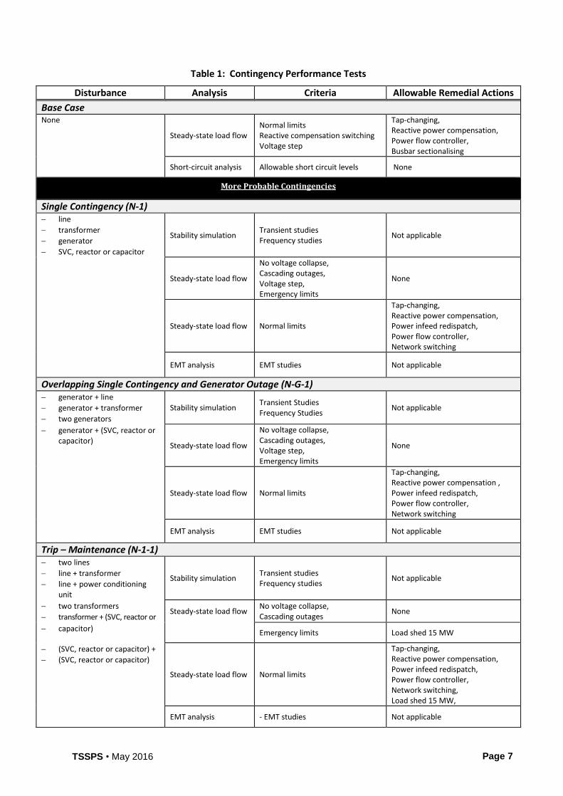
Table 1: Contingency Performance Tests
Disturbance Analysis Criteria Allowable Remedial Actions
Base Case None
Steady-state load flow Normal limits Reactive compensation switching Voltage step
Tap-changing, Reactive power compensation, Power flow controller, Busbar sectionalising
Short-circuit analysis Allowable short circuit levels None
More Probable Contingencies
Single Contingency (N-1) line
transformer
generator
SVC, reactor or capacitor
Stability simulation Transient studies Frequency studies
Not applicable
Steady-state load flow
No voltage collapse, Cascading outages, Voltage step, Emergency limits
None
Steady-state load flow Normal limits
Tap-changing, Reactive power compensation, Power infeed redispatch, Power flow controller, Network switching
EMT analysis EMT studies Not applicable
Overlapping Single Contingency and Generator Outage (N-G-1) generator + line
generator + transformer
two generators
Stability simulation Transient Studies Frequency Studies
Not applicable
generator + (SVC, reactor or capacitor)
Steady-state load flow
No voltage collapse, Cascading outages, Voltage step, Emergency limits
None
Steady-state load flow Normal limits
Tap-changing, Reactive power compensation , Power infeed redispatch, Power flow controller, Network switching
EMT analysis EMT studies Not applicable
Trip – Maintenance (N-1-1) two lines
line + transformer
line + power conditioning unit
Stability simulation Transient studies Frequency studies
Not applicable
two transformers
transformer + (SVC, reactor or Steady-state load flow
No voltage collapse, Cascading outages
None
capacitor) Emergency limits Load shed 15 MW
(SVC, reactor or capacitor) +
(SVC, reactor or capacitor)
Steady-state load flow Normal limits
Tap-changing, Reactive power compensation, Power infeed redispatch, Power flow controller, Network switching, Load shed 15 MW,
EMT analysis - EMT studies Not applicable
TSSPS • May 2016
Page 8
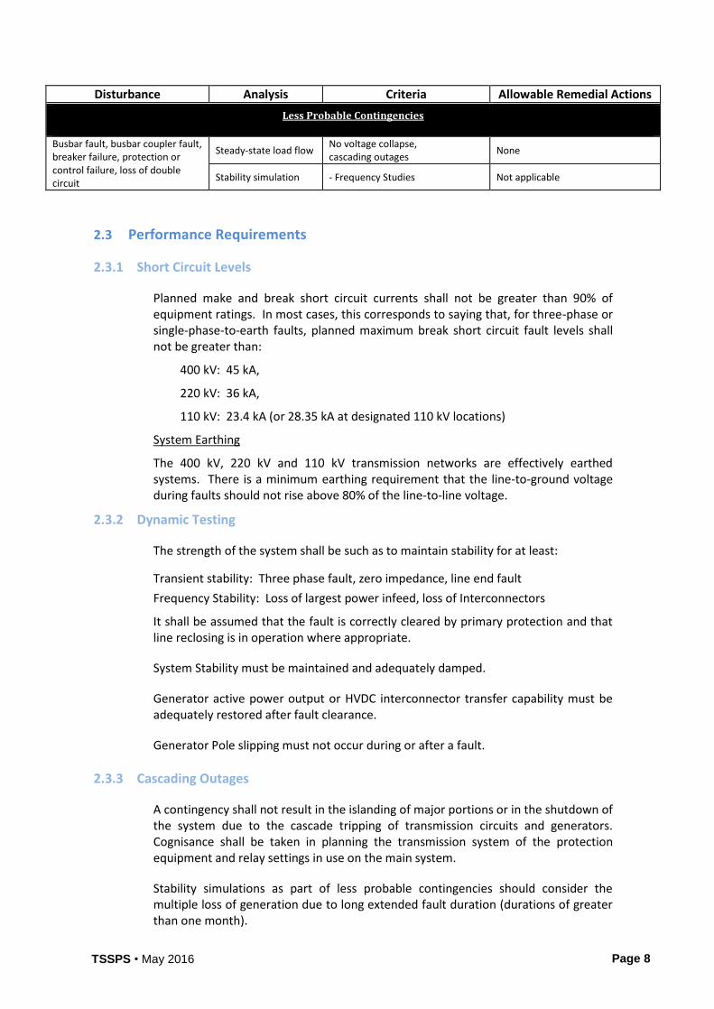
Disturbance Analysis Criteria Allowable Remedial Actions
Less Probable Contingencies
Busbar fault, busbar coupler fault, breaker failure, protection or control failure, loss of double circuit
Steady-state load flow No voltage collapse, cascading outages
None
Stability simulation - Frequency Studies Not applicable
2.3 Performance Requirements
2.3.1 Short Circuit Levels
Planned make and break short circuit currents shall not be greater than 90% of equipment ratings. In most cases, this corresponds to saying that, for three-phase or single-phase-to-earth faults, planned maximum break short circuit fault levels shall not be greater than:
400 kV: 45 kA,
220 kV: 36 kA,
110 kV: 23.4 kA (or 28.35 kA at designated 110 kV locations)
System Earthing
The 400 kV, 220 kV and 110 kV transmission networks are effectively earthed systems. There is a minimum earthing requirement that the line-to-ground voltage during faults should not rise above 80% of the line-to-line voltage.
2.3.2 Dynamic Testing
The strength of the system shall be such as to maintain stability for at least:
Transient stability: Three phase fault, zero impedance, line end fault
Frequency Stability: Loss of largest power infeed, loss of Interconnectors
It shall be assumed that the fault is correctly cleared by primary protection and that line reclosing is in operation where appropriate.
System Stability must be maintained and adequately damped.
Generator active power output or HVDC interconnector transfer capability must be adequately restored after fault clearance.
Generator Pole slipping must not occur during or after a fault.
2.3.3 Cascading Outages
A contingency shall not result in the islanding of major portions or in the shutdown of the system due to the cascade tripping of transmission circuits and generators. Cognisance shall be taken in planning the transmission system of the protection equipment and relay settings in use on the main system.
Stability simulations as part of less probable contingencies should consider the multiple loss of generation due to long extended fault duration (durations of greater than one month).
TSSPS • May 2016
Page 9
2.3.4 Voltage Collapse
A safe margin should be provided between the transmission loading in an area and the voltage collapse point as the transmission loading is increased.
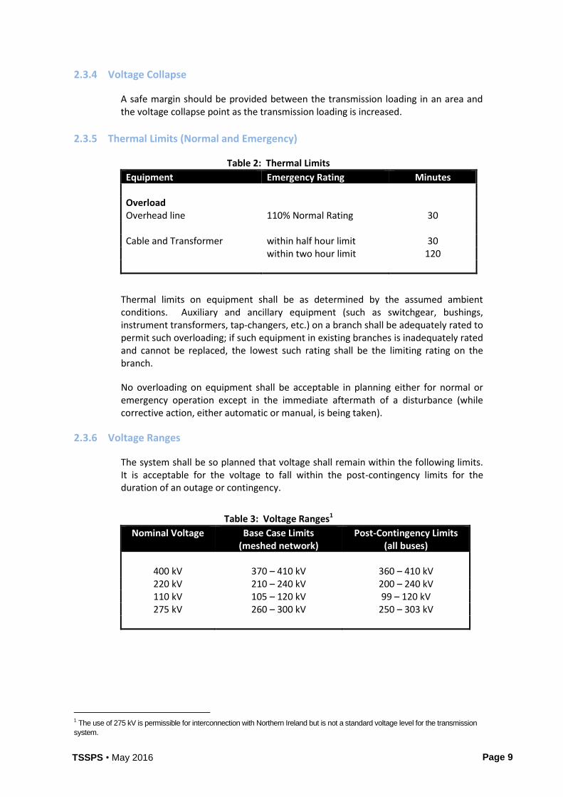
2.3.5 Thermal Limits (Normal and Emergency)
Table 2: Thermal Limits
Equipment Emergency Rating Minutes Overload Overhead line 110% Normal Rating 30 Cable and Transformer within half hour limit 30 within two hour limit 120
Thermal limits on equipment shall be as determined by the assumed ambient conditions. Auxiliary and ancillary equipment (such as switchgear, bushings, instrument transformers, tap-changers, etc.) on a branch shall be adequately rated to permit such overloading; if such equipment in existing branches is inadequately rated and cannot be replaced, the lowest such rating shall be the limiting rating on the branch.
No overloading on equipment shall be acceptable in planning either for normal or emergency operation except in the immediate aftermath of a disturbance (while corrective action, either automatic or manual, is being taken).
2.3.6 Voltage Ranges
The system shall be so planned that voltage shall remain within the following limits. It is acceptable for the voltage to fall within the post-contingency limits for the duration of an outage or contingency.
Table 3: Voltage Ranges1
Nominal Voltage Base Case Limits (meshed network)
Post-Contingency Limits (all buses)
400 kV 370 – 410 kV 360 – 410 kV 220 kV 210 – 240 kV 200 – 240 kV 110 kV 105 – 120 kV 99 – 120 kV 275 kV 260 – 300 kV 250 – 303 kV
1 The use of 275 kV is permissible for interconnection with Northern Ireland but is not a standard voltage level for the transmission
system.
TSSPS • May 2016
Page 10
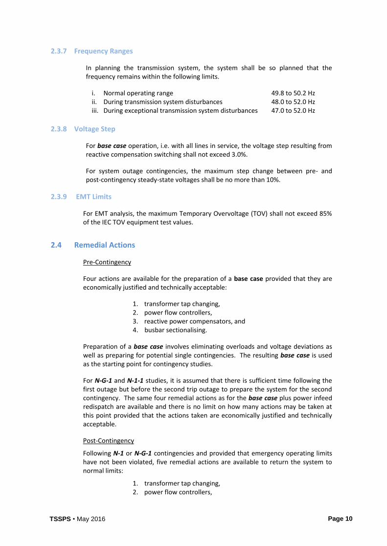
2.3.7 Frequency Ranges
In planning the transmission system, the system shall be so planned that the frequency remains within the following limits.
i. Normal operating range 49.8 to 50.2 Hz ii. During transmission system disturbances 48.0 to 52.0 Hz iii. During exceptional transmission system disturbances 47.0 to 52.0 Hz
2.3.8 Voltage Step
For base case operation, i.e. with all lines in service, the voltage step resulting from reactive compensation switching shall not exceed 3.0%.
For system outage contingencies, the maximum step change between pre- and post-contingency steady-state voltages shall be no more than 10%.
2.3.9 EMT Limits
For EMT analysis, the maximum Temporary Overvoltage (TOV) shall not exceed 85% of the IEC TOV equipment test values.
2.4 Remedial Actions
Pre-Contingency
Four actions are available for the preparation of a base case provided that they are economically justified and technically acceptable:
1. transformer tap changing, 2. power flow controllers, 3. reactive power compensators, and 4. busbar sectionalising.
Preparation of a base case involves eliminating overloads and voltage deviations as well as preparing for potential single contingencies. The resulting base case is used as the starting point for contingency studies.
For N-G-1 and N-1-1 studies, it is assumed that there is sufficient time following the first outage but before the second trip outage to prepare the system for the second contingency. The same four remedial actions as for the base case plus power infeed redispatch are available and there is no limit on how many actions may be taken at this point provided that the actions taken are economically justified and technically acceptable.
Post-Contingency
Following N-1 or N-G-1 contingencies and provided that emergency operating limits have not been violated, five remedial actions are available to return the system to normal limits:
1. transformer tap changing, 2. power flow controllers,
TSSPS • May 2016
Page 11
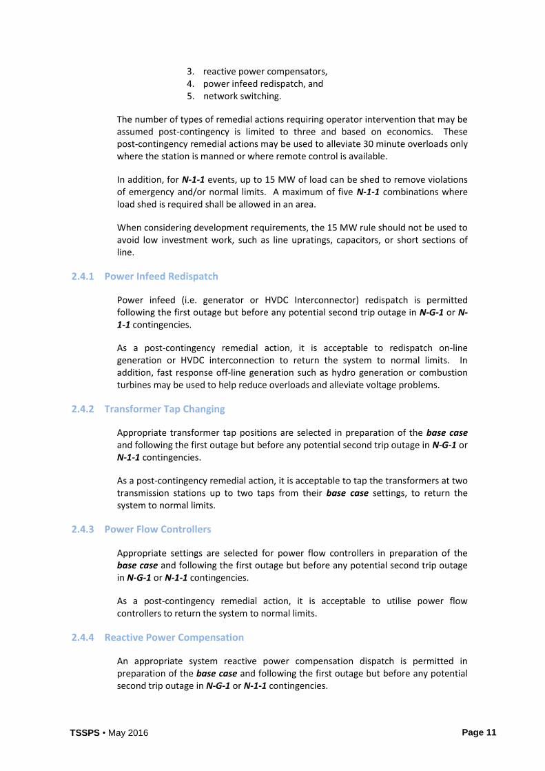
3. reactive power compensators, 4. power infeed redispatch, and 5. network switching.
The number of types of remedial actions requiring operator intervention that may be assumed post-contingency is limited to three and based on economics. These post-contingency remedial actions may be used to alleviate 30 minute overloads only where the station is manned or where remote control is available.
In addition, for N-1-1 events, up to 15 MW of load can be shed to remove violations of emergency and/or normal limits. A maximum of five N-1-1 combinations where load shed is required shall be allowed in an area.
When considering development requirements, the 15 MW rule should not be used to avoid low investment work, such as line upratings, capacitors, or short sections of line.
2.4.1 Power Infeed Redispatch
Power infeed (i.e. generator or HVDC Interconnector) redispatch is permitted following the first outage but before any potential second trip outage in N-G-1 or N-1-1 contingencies.
As a post-contingency remedial action, it is acceptable to redispatch on-line generation or HVDC interconnection to return the system to normal limits. In addition, fast response off-line generation such as hydro generation or combustion turbines may be used to help reduce overloads and alleviate voltage problems.
2.4.2 Transformer Tap Changing
Appropriate transformer tap positions are selected in preparation of the base case and following the first outage but before any potential second trip outage in N-G-1 or N-1-1 contingencies.
As a post-contingency remedial action, it is acceptable to tap the transformers at two transmission stations up to two taps from their base case settings, to return the system to normal limits.
2.4.3 Power Flow Controllers
Appropriate settings are selected for power flow controllers in preparation of the base case and following the first outage but before any potential second trip outage in N-G-1 or N-1-1 contingencies.
As a post-contingency remedial action, it is acceptable to utilise power flow controllers to return the system to normal limits.
2.4.4 Reactive Power Compensation
An appropriate system reactive power compensation dispatch is permitted in preparation of the base case and following the first outage but before any potential second trip outage in N-G-1 or N-1-1 contingencies.
TSSPS • May 2016
Page 12
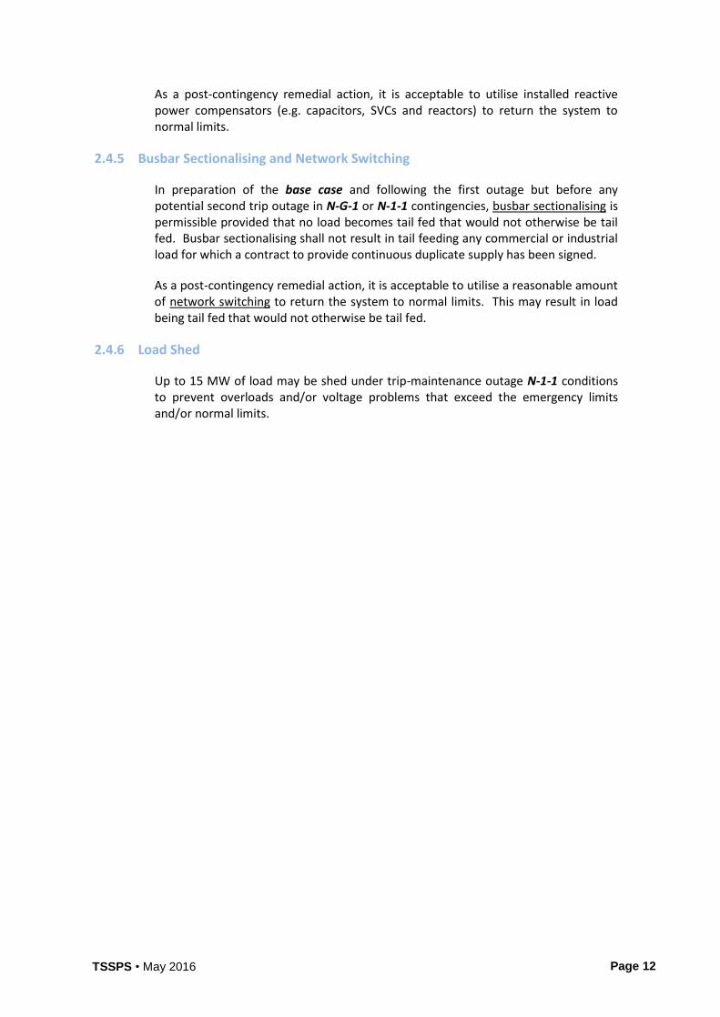
As a post-contingency remedial action, it is acceptable to utilise installed reactive power compensators (e.g. capacitors, SVCs and reactors) to return the system to normal limits.
2.4.5 Busbar Sectionalising and Network Switching
In preparation of the base case and following the first outage but before any potential second trip outage in N-G-1 or N-1-1 contingencies, busbar sectionalising is permissible provided that no load becomes tail fed that would not otherwise be tail fed. Busbar sectionalising shall not result in tail feeding any commercial or industrial load for which a contract to provide continuous duplicate supply has been signed.
As a post-contingency remedial action, it is acceptable to utilise a reasonable amount of network switching to return the system to normal limits. This may result in load being tail fed that would not otherwise be tail fed.
2.4.6 Load Shed
Up to 15 MW of load may be shed under trip-maintenance outage N-1-1 conditions to prevent overloads and/or voltage problems that exceed the emergency limits and/or normal limits.
TSSPS • May 2016
Page 13
3 Modelling Assumptions
3.1 Demand
All tests shall be carried out based on current annual energy and peak demand forecasts, adjusted for the relevant demand level. The performance of the planned system should meet EirGrid Transmission System Security and Planning Standards at peak and other demand levels. Planning of the EirGrid transmission system shall be carried out on the basis of normal configuration of distribution network.
3.2 Generation
All tests shall be based on the best information on generation development.
3.3 Dispatch
Planning of the transmission system shall be carried out on the basis that generation is dispatched according to normal operational methods for a credible range of dispatches.
The strength of the transmission network should be such that:
i. No limitation shall be put on the output of any generation station to the system under normal conditions, i.e. all lines in service.
ii. A pre-arranged complete shutdown of a generation station or part of it (required, for example, because of common equipment such as chimneys, cooling water culverts, etc.) during a suitably chosen low-load period may be tolerated when necessary. During such a shutdown, relevant planned maintenance or other scheduled voluntary outages of generation and/or transmission equipment elsewhere is regarded as being suitably minimised.
3.4 Interconnection
The system shall be capable of transmitting the net flows resulting from the inflows or outflows of an interconnection with any other power system.
TSSPS • May 2016
Page 14
4 Design Criteria
4.1 Supply to Transmission Stations
Any modification or reinforcement used in network simulations will be compliant with the criteria set out below and applicable EirGrid policies and standards.
4.1.1 220 kV Bulk Supply Points and Stations
Two circuits shall be regarded as adequate to connect a 220 kV bulk supply point with a load of less than 300 MVA to the rest of the system. This is provided supply can be restored to load equivalent to one third of winter peak load within two hours for an outage of both circuits.
Any demand station design must not have a total demand of more than 750 MVA that may be supplied by the 220/110kV transformers
4.1.2 400 kV and 220 kV Transmission Stations
In a meshed network area supplied by three 110 kV circuits, the development of a fourth circuit, will provide a circuit designed for 220 kV or greater and include either an economic or environmental assessment.
4.1.3 110 kV Transmission Stations
The provision of a single or duplicate supply to 110/38 kV, 110/20 kV or 110/10 kV stations shall take account of distribution network requirements as well as transmission system requirements.
The loss of two 110 kV circuits shall not disconnect four or more 110 kV stations supplying distribution networks or isolate 80 MW or more of distribution load demand.
Demand stations must not be designed for the purposes of supplying distribution customers loading of more than 90 MW.
4.1.4 110 kV Tees
Unswitched tees represent a degradation of reliability by increasing the amount of line subject to outage and providing for additional exposure to protection and equipment failures.
New unswitched tees are not allowed on the 400 kV, 220 kV and 110 kV systems.
Normal operation, protection and maintenance equipment and practices on the transmission system shall not be affected by the connection of generation capacity to a teed 110kV station or the distribution network fed there from, either at 110 kV or at a lower voltage. High speed automatic reclosing equipment shall not require to be disabled nor shall embedded generation back-feed into a correctly cleared fault on the teed 110 kV line.
TSSPS • May 2016
Page 15
A contingency involving an existing tapped 110 kV line (switched tee) involves loss of all line sections on the tapped line and transfer of the isolated load to alternative 110 kV buses.
A maintenance outage of a section of an existing tapped 110 kV line (switched tee) need only concern the section on which maintenance is being performed. Load is transferred to an alternate 110 kV bus only if the tee section is removed for maintenance. A maintenance outage of an existing tapped 110 kV line (unswitched tee) involves loss of all line sections on the tapped line and transfer of the isolated load to alternate 110 kV buses.
A trip-maintenance combination involving two existing tapped 110 kV lines is a combination of a contingency and a maintenance outage.
4.2 Generation Station and HVDC Interconnector Station Arrangements
Arrangements concerning generation and HVDC Interconnector plant shall be as follows:
i. Power infeed units totalling not more than 35% of the maximum peak power on the system shall be connected either directly or indirectly to only one transmission station, or be situated in a proximity where their operational availability may be simultaneously adversely impacted;
ii. The station arrangement shall be such that the total loss of power infeed units arising from a busbar fault shall not exceed the power rating of the largest power infeed unit on the system. The loss of power infeed units arising from a fault involving a busbar sectionalising or coupling circuit breaker, shall not exceed twice the rating of the largest single power infeed unit on the system.
iii. While, as a general principle, generation plant shall be connected to the main transmission voltage levels, it is permissible to connect generation plant to lower voltage levels where appropriate. However, this should not occur at the cost of simplicity or ease of operation, nor should it hinder future sectionalising of the 110 kV network.
iv. A block of generation capacity in excess of the power rating of the largest generating unit on the system shall be connected to the rest of the system by at least two circuits. It shall be possible where the station capacity exceeds twice the power rating of the largest generation unit on the system, to transmit the full output of the station less the capacity of any one of the units to the system even with a trip-maintenance combination of the connecting circuits.
4.3 Transformer or EHV Cable on Prolonged Outage
Following the loss of a 400/220 kV or 220/110 kV transformer on unscheduled outage longer than one month the transmission system shall be capable of withstanding single N-1 or N-G-1 contingencies.
Following the loss of an EHV cable (345 kV and above) on prolonged unscheduled outage longer than 1 month, the transmission system shall be capable of withstanding single N-1 or N-G-1 contingencies.
TSSPS • May 2016
Page 16
5 Associated Policies
In addition to the requirements set out in Sections 2 to 4, the system shall also be designed and developed in compliance with the various relevant EirGrid policies.