Transmission Line System - LGCE · lhf 12d (1/2 ) lhf 33d (lhf 22d (7/8 ) 1-1/4 ) lhf 42d (1-5/8 )...
23
Transmission Line System LHF Series(Low Loss Flexible Foam Dielectric Feeder) HFC Series(Flexible Foam Dielectric Feeder) HFSC Series(Super Flexible Foam Dielectric Feeder) Jacket Option Packing Information Conversion Table
Transcript of Transmission Line System - LGCE · lhf 12d (1/2 ) lhf 33d (lhf 22d (7/8 ) 1-1/4 ) lhf 42d (1-5/8 )...
Transmission Line System
LHF Series(Low Loss Flexible Foam Dielectric Feeder)
HFC Series(Flexible Foam Dielectric Feeder)
HFSC Series(Super Flexible Foam Dielectric Feeder)
Jacket Option
Packing Information
Conversion Table
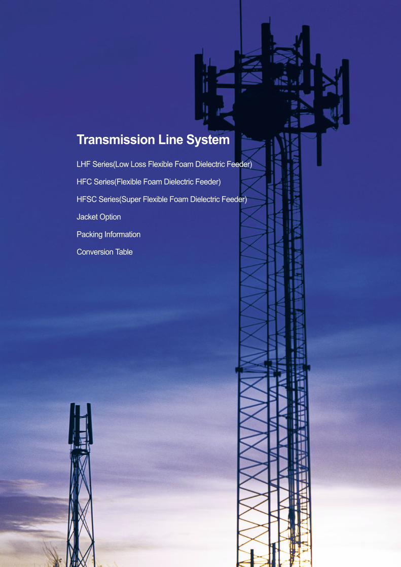
LHF SeriesLow Loss Flexible Foam Dielectric Feeder
LHF Series (Low Loss Flexible Foam Dielectric Feeder)8
1/2 ″LHF 12D / LHF-FR 12D
7/8″LHF 22D / LHF-FR 22D
1-1/4 ″LHF 33D / LHF-FR 33D
1 - 5/8 ″LHF 42D / LHF-FR 42D
Material / Construction Copper-Clad Smooth Smooth Helically CorrugatedAluminum Wire Copper Tube Copper Tube Copper Tube
Diameter () 5.0 9.4 13.7 18.1
Material / Construction Foamed Foamed Foamed Foamed Polyethylene Polyethylene Polyethylene Polyethylene
Diameter () 12.5 22.1 32.5 42.5
Material / Construction Annularly Corrugated Annularly Corrugated Annularly Corrugated Annularly CorrugatedCopper Tube Copper Tube Copper Tube Copper Tube
Diameter () 14.0 24.9 36.0 46.5
Standard Jacket () 16.0 27.9 39.0 50.0
Halogen-Free / 16.0 27.9 39.0 50.0Flame-Retardant Jacket ()
LHF 12D (1/2″) LHF 33D (1-1/4″) LHF 42D (1-5/8″) LHF 22D (7/8″)
Inner Conductor
Dielectric
Outer Conductor
Jacket Diameter
Construction
125 250 380 500
Standard Jacket () -40 ~ +80 -40 ~ +80 -40 ~ +80 -40 ~ +80
Halogen-Free / -30 ~ +80 -30 ~ +80 -30 ~ +80 -30 ~ +80Flame-Retardant Jacket ()
Standard Jacket (/) 244 501 915 1,068
Halogen-Free /262 541 963 1,147Flame-Retardant Jacket (/)
2.0 1.8 2.4 1.6
113 147 260 181
LHF 12D (1/2″) LHF 33D (1-1/4″) LHF 42D (1-5/8″) LHF 22D (7/8″)
Min. Bending Radius ()
Recommended Operating Temperature
Nominal Weight
Flat Plate Crush Resistance (/)
Max. Pulling Force ()
Mechanical Characteristics
LHF Series (Low Loss Flexible Foam Dielectric Feeder) 9
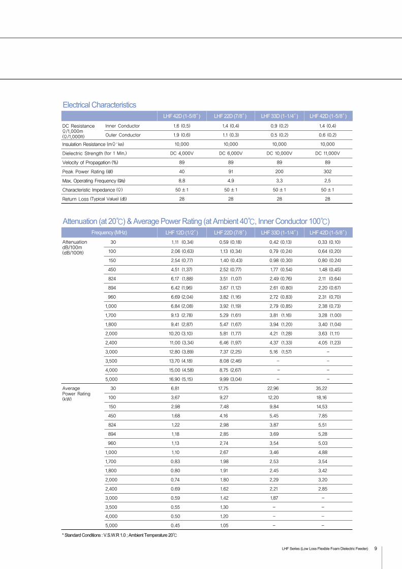
30 1.11 (0.34) 0.59 (0.18) 0.42 (0.13) 0.33 (0.10)
100 2.06 (0.63) 1.13 (0.34) 0.79 (0.24) 0.64 (0.20)
150 2.54 (0.77) 1.40 (0.43) 0.98 (0.30) 0.80 (0.24)
450 4.51 (1.37) 2.52 (0.77) 1.77 (0.54) 1.48 (0.45)
824 6.17 (1.88) 3.51 (1.07) 2.49 (0.76) 2.11 (0.64)
894 6.42 (1.96) 3.67 (1.12) 2.61 (0.80) 2.20 (0.67)
960 6.69 (2.04) 3.82 (1.16) 2.72 (0.83) 2.31 (0.70)
1,000 6.84 (2.08) 3.92 (1.19) 2.79 (0.85) 2.38 (0.73)
1,700 9.13 (2.78) 5.29 (1.61) 3.81 (1.16) 3.28 (1.00)
1,800 9.41 (2.87) 5.47 (1.67) 3.94 (1.20) 3.40 (1.04)
2,000 10.20 (3.10) 5.81 (1.77) 4.21 (1.28) 3.63 (1.11)
2,400 11.00 (3.34) 6.46 (1.97) 4.37 (1.33) 4.05 (1.23)
3,000 12.80 (3.89) 7.37 (2.25) 5.16 (1.57) -
3,500 13.70 (4.18) 8.08 (2.46) - -
4,000 15.00 (4.58) 8.75 (2.67) - -
5,000 16.90 (5.15) 9.99 (3.04) - -
30 6.81 17.75 22.96 35.22
100 3.67 9.27 12.20 18.16
150 2.98 7.48 9.84 14.53
450 1.68 4.16 5.45 7.85
824 1.22 2.98 3.87 5.51
894 1.18 2.85 3.69 5.28
960 1.13 2.74 3.54 5.03
1,000 1.10 2.67 3.46 4.88
1,700 0.83 1.98 2.53 3.54
1,800 0.80 1.91 2.45 3.42
2,000 0.74 1.80 2.29 3.20
2,400 0.69 1.62 2.21 2.85
3,000 0.59 1.42 1.87 -
3,500 0.55 1.30 - -
4,000 0.50 1.20 - -
5,000 0.45 1.05 - -
Inner Conductor 1.6 (0.5) 1.4 (0.4) 0.9 (0.2) 1.4 (0.4)
Outer Conductor 1.9 (0.6) 1.1 (0.3) 0.5 (0.2) 0.6 (0.2)
10,000 10,000 10,000 10,000
DC 4,000V DC 6,000V DC 10,000V DC 11,000V
89 89 89 89
40 91 200 302
8.8 4.9 3.3 2.5
50 ±1 50 ±1 50 ±1 50 ±1
28 28 28 28
LHF 42D (1-5/8″) LHF 33D (1-1/4″) LHF 42D (1-5/8″) LHF 22D (7/8″)
DC ResistanceΩ/1,000m(Ω/1,000ft)
Insulation Resistance (mΩ )
Dielectric Strength (for 1 Min.)
Velocity of Propagation (%)
Peak Power Rating ()
Max. Operating Frequency ()
Characteristic Impedance (Ω)
Return Loss (Typical Value) ()
AttenuationdB/100m(dB/100ft)
Average Power Rating (kW)
Electrical Characteristics
LHF 12D (1/2″)Frequency (MHz) LHF 33D (1-1/4″) LHF 42D (1-5/8″) LHF 22D (7/8″)
Attenuation (at 20) & Average Power Rating (at Ambient 40, Inner Conductor 100)
* Standard Conditions : V.S.W.R 1.0 ; Ambient Temperature 20
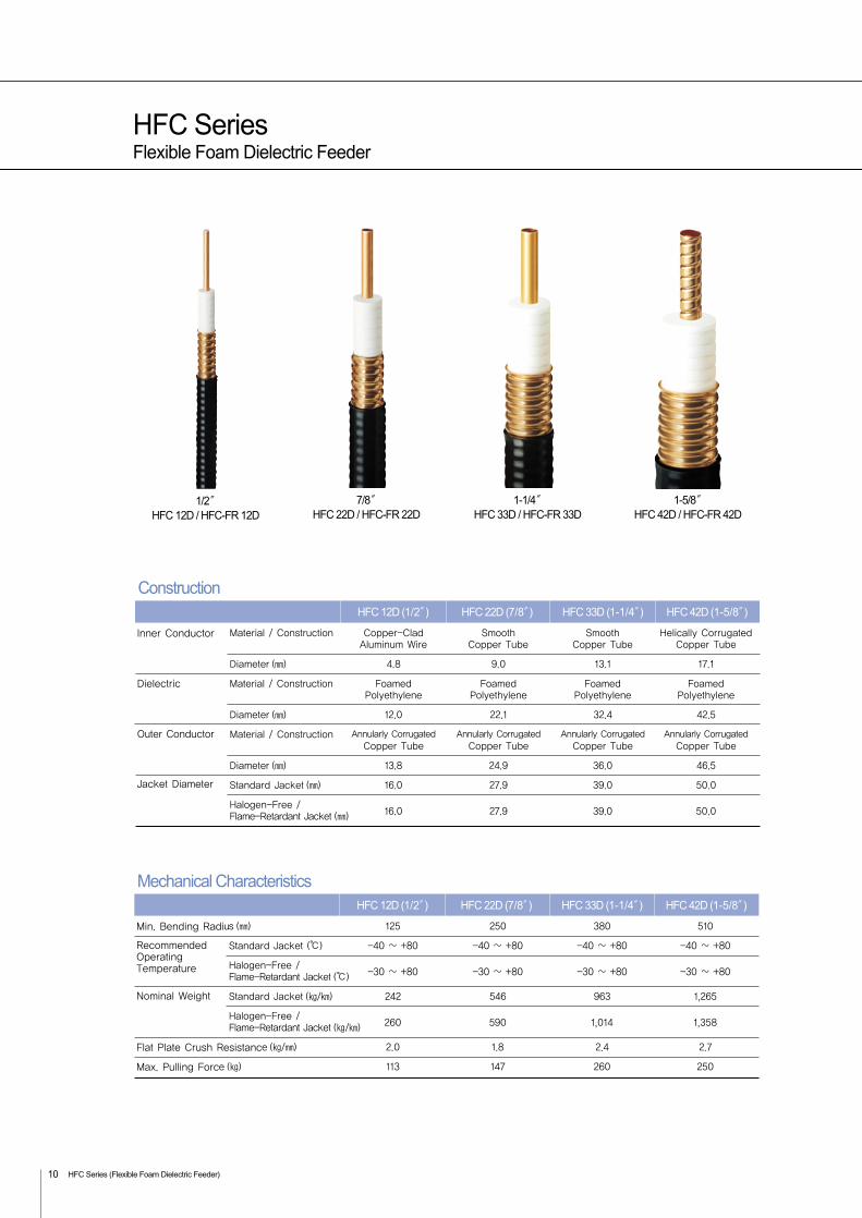
HFC SeriesFlexible Foam Dielectric Feeder
HFC Series (Flexible Foam Dielectric Feeder)10
Material / Construction Copper-Clad Smooth Smooth Helically CorrugatedAluminum Wire Copper Tube Copper Tube Copper Tube
Diameter () 4.8 9.0 13.1 17.1
Material / Construction Foamed Foamed Foamed Foamed Polyethylene Polyethylene Polyethylene Polyethylene
Diameter () 12.0 22.1 32.4 42.5
Material / Construction Annularly Corrugated Annularly Corrugated Annularly Corrugated Annularly CorrugatedCopper Tube Copper Tube Copper Tube Copper Tube
Diameter () 13.8 24.9 36.0 46.5
Standard Jacket () 16.0 27.9 39.0 50.0
Halogen-Free / 16.0 27.9 39.0 50.0Flame-Retardant Jacket ()
1/2 ″HFC 12D / HFC-FR 12D
7/8 ″HFC 22D / HFC-FR 22D
1-1/4 ″HFC 33D / HFC-FR 33D
1-5/8 ″HFC 42D / HFC-FR 42D
HFC 12D (1/2″) HFC 33D (1-1/4″) HFC 42D (1-5/8″) HFC 22D (7/8″)
Inner Conductor
Dielectric
Outer Conductor
Jacket Diameter
Construction
125 250 380 510
Standard Jacket () -40 ~ +80 -40 ~ +80 -40 ~ +80 -40 ~ +80
Halogen-Free / -30 ~ +80 -30 ~ +80 -30 ~ +80 -30 ~ +80Flame-Retardant Jacket ()
Standard Jacket (/) 242 546 963 1,265
Halogen-Free /260 590 1,014 1,358Flame-Retardant Jacket (/)
2.0 1.8 2.4 2.7
113 147 260 250
HFC 12D (1/2″) HFC 33D (1-1/4″) HFC 42D (1-5/8″) HFC 22D (7/8″)
Min. Bending Radius ()
Recommended Operating Temperature
Nominal Weight
Flat Plate Crush Resistance (/)
Max. Pulling Force ()
Mechanical Characteristics

HFC Series (Flexible Foam Dielectric Feeder) 11
30 1.17 (0.36) 0.64 (0.20) 0.44 (0.13) 0.36 (0.11)
100 2.17 (0.66) 1.19 (0.36) 0.83 (0.25) 0.67 (0.20)
150 2.67 (0.81) 1.47 (0.45) 1.03 (0.31) 0.84 (0.26)
450 4.75 (1.45) 2.65 (0.81) 1.86 (0.57) 1.53 (0.47)
824 6.49 (1.98) 3.68 (1.12) 2.62 (0.80) 2.17 (0.66)
890 6.76 (2.05) 3.85 (1.18) 2.75 (0.84) 2.27 (0.69)
960 7.04 (2.15) 4.01 (1.22) 2.86 (0.87) 2.38 (0.73)
1,000 7.20 (2.19) 4.10 (1.25) 2.94 (0.90) 2.43 (0.74)
1,700 9.61 (2.93) 5.54 (1.69) 4.01 (1.22) 3.35 (1.02)
1,800 9.91 (3.02) 5.73 (1.75) 4.15 (1.26) 3.47 (1.06)
2,000 10.70 (3.26) 6.09 (1.86) 4.43 (1.35) 3.71 (1.13)
2,300 11.54 (3.52) 6.63 (2.02) 4.60 (1.40) 4.07 (1.24)
3,000 13.44 (4.10) 7.81 (2.38) 5.43 (1.66)
3,400 14.44 (4.40) 8.52 (2.59)
4,000 15.81 (4.82) 9.42 (2.87)
5,000 17.77 (5.42) 10.84 (3.30)
30 6.26 14.18 22.12 30.52
100 3.43 7.63 11.73 16.40
150 2.79 6.17 9.45 13.08
450 1.56 3.43 5.23 6.95
824 1.15 2.46 3.72 4.80
890 1.10 2.35 3.54 4.62
960 1.07 2.26 3.40 4.43
1,000 1.04 2.20 3.31 4.31
1,700 0.78 1.63 2.43 3.13
1,800 0.75 1.53 2.35 2.98
2,000 0.70 1.49 2.20 2.76
2,300 0.65 1.36 1.50 2.51
3,000 0.56 1.16 1.80
3,400 0.52 1.06
4,000 0.48 0.96
5,000 0.43 0.83
Inner Conductor 1.55 (0.47) 1.05 (0.32) 0.72 (0.22) 0.85 (0.26)
Outer Conductor 1.9 (0.58) 1.05 (0.32) 0.45 (0.14) 0.36 (0.11)
10,000 10,000 10,000 10,000
DC 4,000V DC 6,000V DC 9,000V DC 11,000V
88 88 88 88
40 91 205 315
8.8 5 3.3 2.5
50 ±1 50 ±1 50 ±1 50 ±1
28 28 28 28
HFC 12D (1/2″) HFC 33D (1-1/4″) HFC 42D (1-5/8″) HFC 22D (7/8″)
Insulation Resistance (mΩ )
Dielectric Strength (for 1 Min.)
Velocity of Propagation (%)
Peak Power Rating ()
Max. Operating Frequency ()
Characteristic Impedance (Ω)
Return Loss (Typical Value) ()
AttenuationdB/100m(dB/100ft)
Average Power Rating (kW)
Electrical Characteristics
HFC 12D (1/2″) Frequency (MHz) HFC 33D (1-1/4″) HFC 42D (1-5/8″) HFC 22D (7/8″)
Attenuation (at 20) & Average Power Rating (at Ambient 40, Inner Conductor 100)
* Standard Conditions : V.S.W.R 1.0 ; Ambient Temperature 20
-
-
-
-
-
-
-
-
-
-
-
-
-
-
DC ResistanceΩ/1,000m(Ω/1,000ft)
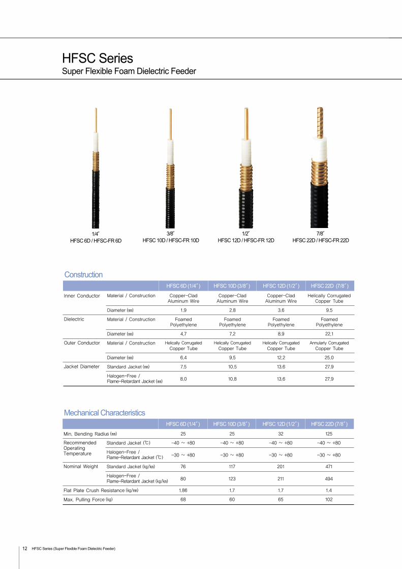
HFSC SeriesSuper Flexible Foam Dielectric Feeder
HFSC Series (Super Flexible Foam Dielectric Feeder)12
Material / Construction Copper-Clad Copper-Clad Copper-Clad Helically CorrugatedAluminum Wire Aluminum Wire Aluminum Wire Copper Tube
Diameter () 1.9 2.8 3.6 9.5
Material / Construction Foamed Foamed Foamed FoamedPolyethylene Polyethylene Polyethylene Polyethylene
Diameter () 4.7 7.2 8.9 22.1
Material / Construction Helically Corrugated Helically Corrugated Helically Corrugated Annularly CorrugatedCopper Tube Copper Tube Copper Tube Copper Tube
Diameter () 6.4 9.5 12.2 25.0
Standard Jacket () 7.5 10.5 13.6 27.9
Halogen-Free / 8.0 10.8 13.6 27.9Flame-Retardant Jacket ()
1/4″HFSC 6D / HFSC-FR 6D
3/8″HFSC 10D / HFSC-FR 10D
1/2″HFSC 12D / HFSC-FR 12D
7/8″HFSC 22D / HFSC-FR 22D
HFSC 6D (1/4″) HFSC 12D (1/2″) HFSC 22D (7/8″) HFSC 10D (3/8″)
Inner Conductor
Dielectric
Outer Conductor
Jacket Diameter
Construction
25 25 32 125
Standard Jacket () -40 ~ +80 -40 ~ +80 -40 ~ +80 -40 ~ +80
Halogen-Free /-30 ~ +80 -30 ~ +80 -30 ~ +80 -30 ~ +80Flame-Retardant Jacket ()
Standard Jacket (/) 76 117 201 471
Halogen-Free /80 123 211 494Flame-Retardant Jacket (/)
1.86 1.7 1.7 1.4
68 60 65 102
HFSC 6D (1/4″) HFSC 12D (1/2″) HFSC 22D (7/8″) HFSC 10D (3/8″)
Min. Bending Radius ()
Recommended Operating Temperature
Nominal Weight
Flat Plate Crush Resistance (/)
Max. Pulling Force ()
Mechanical Characteristics
HFSC Series (Super Flexible Foam Dielectric Feeder) 13
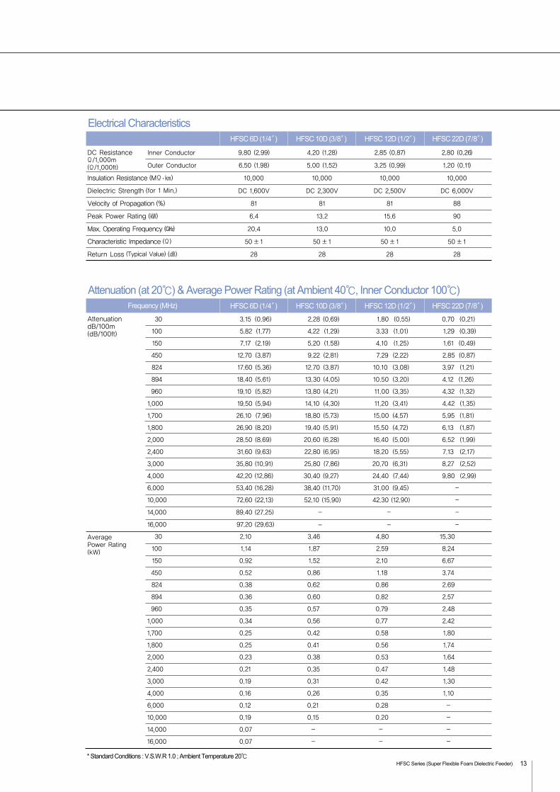
Inner Conductor 9.80 (2.99) 4.20 (1.28) 2.85 (0.87) 2.80 (0.26)
Outer Conductor 6.50 (1.98) 5.00 (1.52) 3.25 (0.99) 1.20 (0.11)
10,000 10,000 10,000 10,000
DC 1,600V DC 2,300V DC 2,500V DC 6,000V
81 81 81 88
6.4 13.2 15.6 90
20.4 13.0 10.0 5.0
50 ±1 50 ±1 50 ±1 50 ±1
28 28 28 28
HFSC 6D (1/4″) HFSC 12D (1/2″) HFSC 22D (7/8″) HFSC 10D (3/8″)
DC ResistanceΩ/1,000m(Ω/1,000ft)
Insulation Resistance (MΩ )
Dielectric Strength (for 1 Min.)
Velocity of Propagation (%)
Peak Power Rating ()
Max. Operating Frequency ()
Characteristic Impedance (Ω)
Return Loss (Typical Value) ()
Electrical Characteristics
30 3.15 (0.96) 2.28 (0.69) 1.80 (0.55) 0.70 (0.21)
100 5.82 (1.77) 4.22 (1.29) 3.33 (1.01) 1.29 (0.39)
150 7.17 (2.19) 5.20 (1.58) 4.10 (1.25) 1.61 (0.49)
450 12.70 (3.87) 9.22 (2.81) 7.29 (2.22) 2.85 (0.87)
824 17.60 (5.36) 12.70 (3.87) 10.10 (3.08) 3.97 (1.21)
894 18.40 (5.61) 13.30 (4.05) 10.50 (3.20) 4.12 (1.26)
960 19.10 (5.82) 13.80 (4.21) 11.00 (3.35) 4.32 (1.32)
1,000 19.50 (5.94) 14.10 (4.30) 11.20 (3.41) 4.42 (1.35)
1,700 26.10 (7.96) 18.80 (5.73) 15.00 (4.57) 5.95 (1.81)
1,800 26.90 (8.20) 19.40 (5.91) 15.50 (4.72) 6.13 (1.87)
2,000 28.50 (8.69) 20.60 (6.28) 16.40 (5.00) 6.52 (1.99)
2,400 31.60 (9.63) 22.80 (6.95) 18.20 (5.55) 7.13 (2.17)
3,000 35.80 (10.91) 25.80 (7.86) 20.70 (6.31) 8.27 (2.52)
4,000 42.20 (12.86) 30.40 (9.27) 24.40 (7.44) 9.80 (2.99)
6.000 53.40 (16.28) 38.40 (11.70) 31.00 (9.45) -
10,000 72.60 (22.13) 52.10 (15.90) 42.30 (12.90) -
14,000 89.40 (27.25) -
16,000 97.20 (29.63) -
30 2.10 3.46 4.80 15.30
100 1.14 1.87 2.59 8.24
150 0.92 1.52 2.10 6.67
450 0.52 0.86 1.18 3.74
824 0.38 0.62 0.86 2.69
894 0.36 0.60 0.82 2.57
960 0.35 0.57 0.79 2.48
1,000 0.34 0.56 0.77 2.42
1,700 0.25 0.42 0.58 1.80
1,800 0.25 0.41 0.56 1.74
2,000 0.23 0.38 0.53 1.64
2,400 0.21 0.35 0.47 1.48
3,000 0.19 0.31 0.42 1.30
4,000 0.16 0.26 0.35 1.10
6,000 0.12 0.21 0.28
10,000 0.19 0.15 0.20
14,000 0.07
16,000 0.07
AttenuationdB/100m(dB/100ft)
Average Power Rating (kW)
HFSC 6D (1/4″) Frequency (MHz) HFSC 12D (1/2″) HFSC 22D (7/8″) HFSC 10D (3/8″)
Attenuation (at 20) & Average Power Rating (at Ambient 40, Inner Conductor 100)
* Standard Conditions : V.S.W.R 1.0 ; Ambient Temperature 20
-
-
-
-
-
-
-
-
-
-
-
-
- - - -
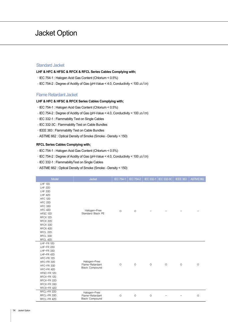
Halogen-Free Flame-Retardant Black Compound
Halogen-Free Flame-Retardant - - Black Compound
LHF 12DLHF 22DLHF 33DLHF 42DHFC 12DHFC 22DHFC 33DHFC 42DHFSC 12DRFCX 12DRFCX 22DRFCX 33DRFCX 42DRFCL 22DRFCL 33DRFCL 42DLHF-FR 12DLHF-FR 22DLHF-FR 33DLHF-FR 42DHFC-FR 12DHFC-FR 22DHFC-FR 33DHFC-FR 42DHFSC-FR 12DRFCX-FR 12DRFCX-FR 22DRFCX-FR 33DRFCX-FR 42DRFCL-FR 22DRFCL-FR 33DRFCL-FR 42D
ASTM E 662IEEE 383IEC 332-3CIEC 332-1IEC 754-2IEC 754-1Model Jacket
Jacket Option
Jacket Option14
Standard JacketLHF & HFC & HFSC & RFCX & RFCL Series Cables Complying with;
·IEC 754-1 : Halogen Acid Gas Content (Chlorium < 0.5%)
·IEC 754-2 : Degree of Acidity of Gas (pH-Value < 4.0, Conductivity < 100 /)
Flame Retardant JacketLHF & HFC & HFSC & RFCX Series Cables Complying with;
·IEC 754-1 : Halogen Acid Gas Content (Chlorium < 0.5%)
·IEC 754-2 : Degree of Acidity of Gas (pH-Value < 4.0, Conductivity < 100 /)
·IEC 332-1 : Flammability Test on Single Cables
·IEC 332-3C : Flammability Test on Cable Bundles
·IEEE 383 : Flammability Test on Cable Bundles
·ASTME 662 : Optical Density of Smoke (Smoke - Density < 150)
RFCL Series Cables Complying with;
·IEC 754-1 : Halogen Acid Gas Content (Chlorium < 0.5%)
·IEC 754-2 : Degree of Acidity of Gas (pH-Value < 4.0, Conductivity < 100 /)
·IEC 332-1 : FlammabilityTest on Single Cables
·ASTME 662 : Optical Density of Smoke (Smoke - Density < 150)
Halogen-FreeStandard Black PE
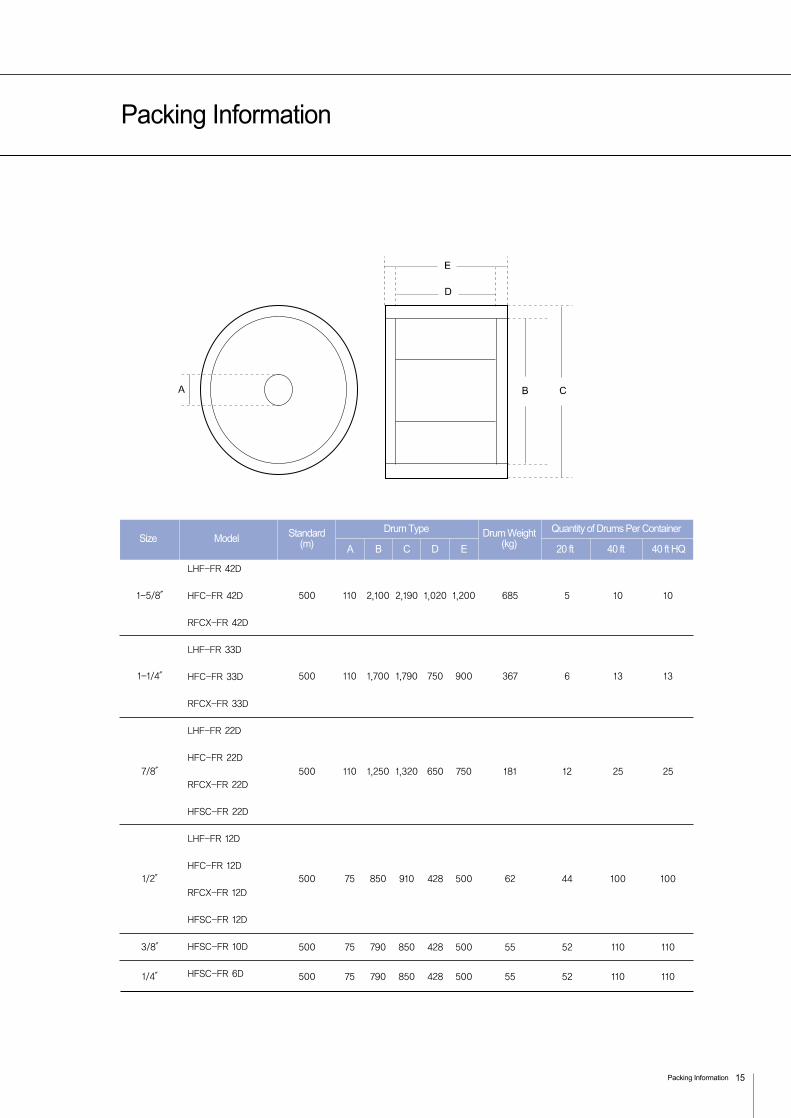
Packing Information
Packing Information 15
1-5/8″
1-1/4″
7/8″
1/2″
3/8″
1/4″
500
500
500
500
500
500
110
110
110
75
75
75
2,100
1,700
1,250
850
790
790
2,190
1,790
1,320
910
850
850
1,020
750
650
428
428
428
1,200
900
750
500
500
500
685
367
181
62
55
55
5
6
12
44
52
52
10
13
25
100
110
110
10
13
25
100
110
110
LHF-FR 42D
HFC-FR 42D
RFCX-FR 42D
LHF-FR 33D
HFC-FR 33D
RFCX-FR 33D
LHF-FR 22D
HFC-FR 22D
RFCX-FR 22D
HFSC-FR 22D
LHF-FR 12D
HFC-FR 12D
RFCX-FR 12D
HFSC-FR 12D
HFSC-FR 10D
HFSC-FR 6D
A 20 ft 40 ft 40 ft HQB C D ESize Model Standard
(m)Drum Weight
(kg)
Drum Type Quantity of Drums Per Container
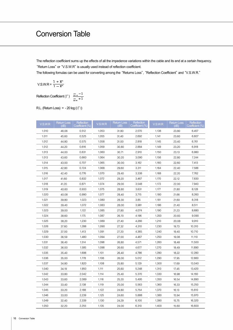
Conversion Table
Conversion Table16
1.010 0.512 1.053 2.570 1.138 6.457
1.011 0.525 1.055 2.692 1.141 6.607
1.012 0.575 1.058 2.818 1.145 6.761
1.012 0.616 1.059 2.884 1.149 6.918
1.013 0.631 1.060 2.910 1.150 6.980
1.013 0.660 1.064 3.090 1.156 7.244
1.014 0.707 1.065 3.162 1.160 7.413
1.015 0.724 1.068 3.311 1.164 7.586
1.016 0.776 1.070 3.338 1.168 7.762
1.017 0.832 1.072 3.467 1.170 7.830
1.018 0.871 1.074 3.548 1.173 7.943
1.019 0.933 1.075 3.631 1.177 8.128
1.020 0.990 1.077 3.715 1.180 8.260
1.021 1.023 1.080 3.85 1.181 8.318
1.022 1.072 1.083 3.981 1.186 8.511
1.023 1.122 1.085 4.074 1.190 8.680
1.024 1.175 1.087 4.196 1.200 9.090
1.025 1.230 1.089 4.266 1.210 9.910
1.026 1.288 1.090 4.310 1.230 10.310
1.029 1.413 1.091 4.365 1.240 10.710
1.030 1.480 1.094 4.467 1.250 11.110
1.031 1.514 1.096 4.571 1.260 11.500
1.032 1.585 1.098 4.677 1.270 11.890
1.035 1.698 1.101 4.786 1.280 12.280
1.036 1.778 1.106 5.012 1.290 12.660
1.037 1.820 1.108 5.129 1.300 13.040
1.040 1.950 1.111 5.248 1.310 13.420
1.042 2.042 1.114 5.370 1.330 14.160
1.043 2.089 1.116 5.495 1.350 14.890
1.044 2.138 1.119 5.563 1.360 15.250
1.045 2.188 1.122 5.754 1.370 15.610
1.046 2.239 1.125 5.888 1.380 15.970
1.049 2.339 1.130 6.100 1.390 16.320
1.050 2.255 1.135 6.310 1.400 16.600
V.S.W.R ReflectionCoefficient (%)
Return Loss(dB) HFC 22D HFC 42D
The reflection coefficient sums up the effects of all the impedence variations within the cable and its end at a certain frequency.
“Return Loss”or “V.S.W.R”is usually used instead of reflection coefficient.
The following fomulas can be used for converting among the “Returns Loss”, “Reflection Coefficient”and “V.S.W.R.”
Reflection Coefficient (Г)
R.L. (Return Loss) = - 20 log (lГl)
V.S.W.R =
V.S.W.R ReflectionCoefficient (%)
Return Loss(dB) V.S.W.R Reflection
Coefficient (%)Return Loss
(dB)
46.06 31.80 23.80
45.60 31.40 23.60
44.80 31.00 23.40
44.20 30.80 23.20
44.00 30.71 23.13
43.60 30.20 22.80
43.00 30.00 22.60
42.80 29.60 22.40
42.40 29.40 22.20
41.60 29.20 22.12
41.20 29.00 22.00
40.60 28.80 21.80
40.08 28.40 21.66
39.80 28.30 21.60
39.40 28.00 21.40
39.00 27.80 21.23
38.60 26.70 20.83
38.20 27.40 20.08
37.60 27.32 19.73
37.00 27.20 19.40
36.59 27.00 19.08
36.40 26.80 18.48
36.00 26.60 18.49
35.40 26.40 18.22
35.00 26.00 17.95
34.80 25.80 17.69
34.19 25.60 17.45
33.80 25.40 16.98
33.60 25.20 16.54
33.40 25.00 16.33
33.20 24.80 16.13
33.00 24.60 15.94
32.40 24.29 15.75
32.20 24.00 15.60

In-Building Solution
Indoor Products
Passive Component
Wide Band Power Splitter
Wide Band Power Tapper
Directional Coupler
3dB Hybrid Coupler
Combiner
Dual Band Combiner
Triple Band Combiner
Indoor Antenna
Dual Band Omni Antenna
Multi Band Omni Antenna
Dual Band Patch Antenna
Multi Band Patch Antenna
Wide Band Yagi Antenna
Radiating Cable
RFCX Series
RFCL Series

LS Cable offers application-driven indoor solution for tunnel or in-building to make the mobile phone signal or
emergency communication signal reach the normal fixed network in indoor coverage systems. We offer a more
complete product range consisting of passive distribution product, indoor ant, radiating cable and other accessories.
With this one-stop shopping package, we guarantee our customers the proper operation of our products and offer
technical support to our indoor coverage customers.
Indoor Products
ApplicationsHigh Rise Buildings / Hotel / Shopping Center / Airport / Tunnels / Metros / Campus Area
Coverage for Wireless Technologe
TETRA 380 / TETRA 450 / TETRA 800 / CDMA 800 / GSM 900 / GSM / DCS 1800 / PCS 1900
W-CDMA 2100 / Wimax / WLAN
Technical Service Coverage
Site Survey / System Design / Installation ( also subcontraction to local Companies ) / Training
Supervision / Commissioning / Acceptance Tests
Passive Component (Wide Band Power Splitter) 19
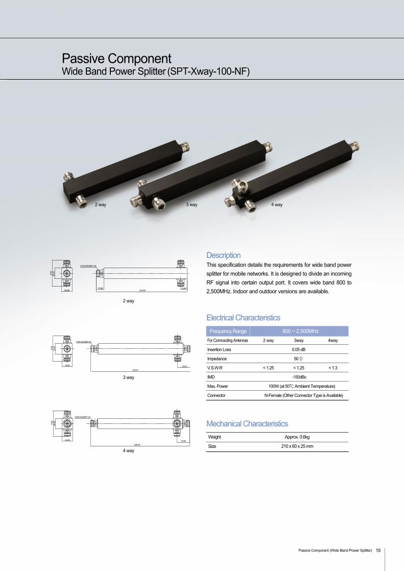
Passive ComponentWide Band Power Splitter (SPT-Xway-100-NF)
DescriptionThis specification details the requirements for wide band power
splitter for mobile networks. It is designed to divide an incoming
RF signal into certain output port. It covers wide band 800 to
2,500MHz. Indoor and outdoor versions are available.
Electrical Characteristics
For Conncecting Antennas 2 way 3way 4way
Insertion Loss 0.05 dB
Impedance 50 Ω
V.S.W.R < 1.25 < 1.25 < 1.3
IMD -150dBc
Max. Power 100W (at 50Ambient Temperature)
Connector N-Female (Other Connector Type is Available)
800 ~ 2,500MHzFrequency Range
Mechanical Characteristics
Size
Weight
210 x 60 x 25 mm
Approx. 0.6kg
2 way 3 way
4 way
2 way
3 way
4 way
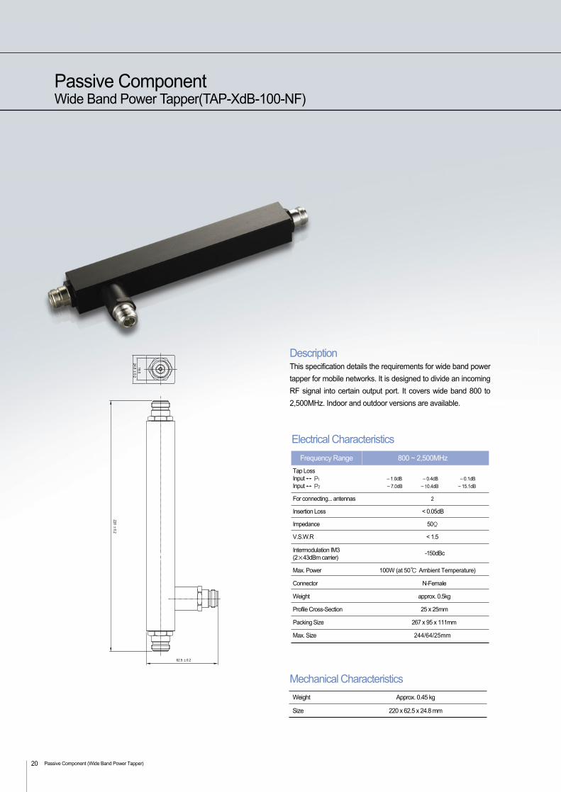
Passive ComponentWide Band Power Tapper(TAP-XdB-100-NF)
Passive Component (Wide Band Power Tapper) 20
DescriptionThis specification details the requirements for wide band power
tapper for mobile networks. It is designed to divide an incoming
RF signal into certain output port. It covers wide band 800 to
2,500MHz. Indoor and outdoor versions are available.
Mechanical Characteristics
Size
Weight
220 x 62.5 x 24.8 mm
Approx. 0.45 kg
Electrical Characteristics
Tap LossInput P1 -1.0dB -0.4dB -0.1dB
Input P2 -7.0dB -10.4dB -15.1dB
For connecting... antennas 2
Insertion Loss < 0.05dB
Impedance 50Ω
V.S.W.R < 1.5
Intermodulation IM3(2×43dBm carrier)
Max. Power 100W (at 50 Ambient Temperature)
Connector N-Female
Weight approx. 0.5kg
Profile Cross-Section 25 x 25mm
Packing Size 267 x 95 x 111mm
Max. Size 244/64/25mm
-150dBc
800 ~ 2,500MHzFrequency Range
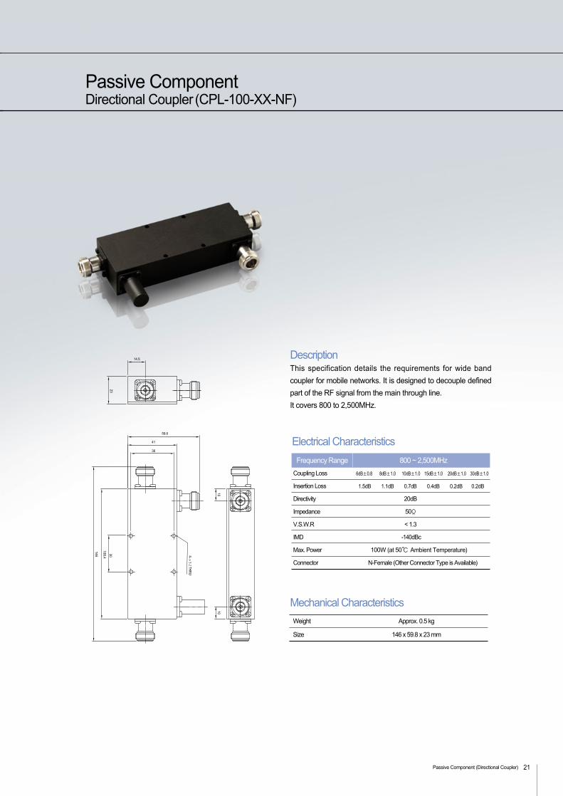
Passive ComponentDirectional Coupler (CPL-100-XX-NF)
Passive Component (Directional Coupler) 21
DescriptionThis specification details the requirements for wide band
coupler for mobile networks. It is designed to decouple defined
part of the RF signal from the main through line.
It covers 800 to 2,500MHz.
Mechanical Characteristics
Size
Weight
146 x 59.8 x 23 mm
Approx. 0.5 kg
Electrical Characteristics
Coupling Loss 6dB±0.8 8dB±1.0 10dB±1.0 15dB±1.0 20dB±1.0 30dB±1.0
Insertion Loss 1.5dB 1.1dB 0.7dB 0.4dB 0.2dB 0.2dB
Directivity 20dB
Impedance 50Ω
V.S.W.R < 1.3
IMD -140dBc
Max. Power 100W (at 50 Ambient Temperature)
Connector N-Female (Other Connector Type is Available)
800 ~ 2,500MHzFrequency Range
Passive Component (3dB Hybrid Coupler)22
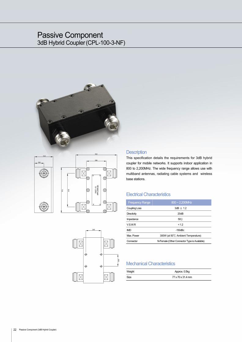
Passive Component3dB Hybrid Coupler (CPL-100-3-NF)
DescriptionThis specification details the requirements for 3dB hybrid
coupler for mobile networks. It supports indoor application in
800 to 2,200MHz. The wide frequency range allows use with
multiband antennas, radiating cable systems and wireless
base stations.
Electrical Characteristics
Coupling Loss 3dB ± 1.2
Directivity 20dB
Impedance 50Ω
V.S.W.R < 1.2
IMD -150dBc
Max. Power 300W (at 50 Ambient Temperature)
Connector N-Female (Other Connector Type is Available)
800 ~ 2,200MHzFrequency Range
Mechanical Characteristics
Size
Weight
77 x 70 x 31.4 mm
Approx. 0.5kg
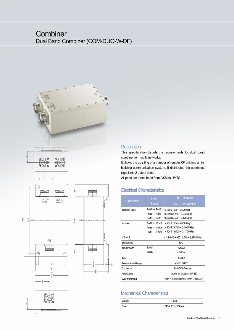
DescriptionThis specification details the requirements for dual band
combiner for mobile networks.
It allows the co-siting of a number of remote RF unit into an in-
building communication system. It distributes the combined
signal into 2 output ports.
All ports are broad band from GSM to UMTS.
Electrical Characteristics
Insertion Loss 0.15dB (806 ~ 960MHz)
0.25dB (1,710 ~ 2,000MHz)
0.35dB (2,000 ~ 2,170MHz)
Isolation > 50dB (806 ~ 960MHz)
> 50dB (1,710 ~ 2,000MHz)
> 50dB (2,000 ~ 2,170MHz)
V.S.W.R < 1.2 (806 ~ 960 / 1,710 ~ 2,170 MHz)
Impedance 50Ω
Input Power < 250W
< 200W
IMD -150dBc
Temperature Range - 55 +60
Connector 7/16DIN-Female
Application Indoor or Outdoor (IP 66)
Wall Mounting With 4 Screws (Max. 8mm Diameter)
Port1 ↔ Port3
Port2 ↔ Port3
Port2 ↔ Port3
Port1 ↔ Port3
Port2 ↔ Port3
Port2 ↔ Port3
Band1
Band2
806 ~ 960MHz
1,710 ~ 2,170MHz
Band1
Band2Pass Band
Mechanical Characteristics
Size
Weight
245 x 111 x 69mm
1.6kg
Combiner (Dual Band Combiner) 23
CombinerDual Band Combiner (COM-DUO-W-DF)
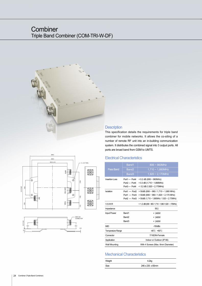
CombinerTriple Band Combiner (COM-TRI-W-DF)
Combiner (Triple Band Combiner)24
DescriptionThis specification details the requirements for triple band
combiner for mobile networks. It allows the co-siting of a
number of remote RF unit into an in-building communication
system. It distributes the combined signal into 3 output ports. All
ports are broad band from GSM to UMTS.
Electrical Characteristics
Insertion Loss < 0.2 dB (806 ~ 960MHz)
< 0.3 dB (1,710 ~ 1,880MHz)
< 0.2 dB (1,920 ~ 2,170MHz)
Isolation > 50dB (806 ~ 960 / 1,710 ~ 1,880 MHz)
> 50dB (806 ~ 960 / 1,920 ~ 2,170 MHz)
> 50dB (1,710 ~ 1,880MHz / 1,920 ~ 2,170MHz)
V.S.W.R < 1.2 dB(806 ~ 960 / 1,710 ~ 1,880 /1,920 ~ ,170MHz)
Impedance 50Ω
< 240W
< 240W
< 240W
IMD -150dBc
Temperature Range -40 +60
Connector 7/16DIN-Female
Application Indoor or Outdoor (IP 66)
Wall Mounting With 4 Screws (Max. 8mm Diameter)
Port1 ↔ Port4
Port2 ↔ Port4
Port3 ↔ Port4
Port1 ↔ Port2
Port1 ↔ Port3
Port2 ↔ Port3
Band1
Band2
Band3
806 ~ 960MHz
1,710 ~ 1,880MHz
1,920 ~ 2,170MHz
Band1
Band2
Band3
Pass Band
Mechanical Characteristics
Size
Weight
246 x 235 x 65mm
4.2kg
Input Power
Indoor Antenna (Dual Band Omni Antenna)
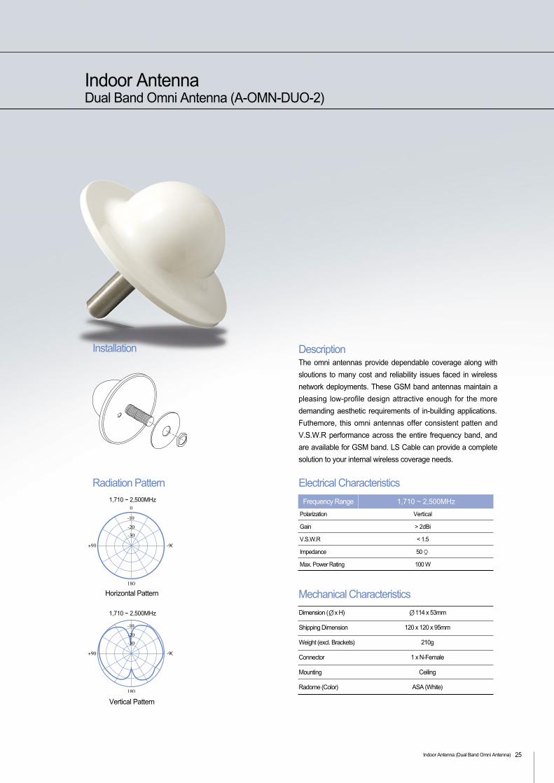
Indoor AntennaDual Band Omni Antenna (A-OMN-DUO-2)
1,710 ~ 2,500MHz
Horizontal Pattern
1,710 ~ 2,500MHz
Vertical Pattern
DescriptionThe omni antennas provide dependable coverage along with
sloutions to many cost and reliability issues faced in wireless
network deployments. These GSM band antennas maintain a
pleasing low-profile design attractive enough for the more
demanding aesthetic requirements of in-building applications.
Futhemore, this omni antennas offer consistent patten and
V.S.W.R performance across the entire frequency band, and
are available for GSM band. LS Cable can provide a complete
solution to your internal wireless coverage needs.
Ø114 x 53mm
120 x 120 x 95mm
210g
1 x N-Female
Ceiling
ASA (White)
Dimension (Øx H)
Shipping Dimension
Weight (excl. Brackets)
Connector
Mounting
Radome (Color)
Electrical Characteristics
Installation
Radiation Pattern
Polarization Vertical
Gain > 2dBi
V.S.W.R < 1.5
Impedance 50 Ω
Max. Power Rating 100 W
1,710 ~ 2,500MHzFrequency Range
Mechanical Characteristics
25
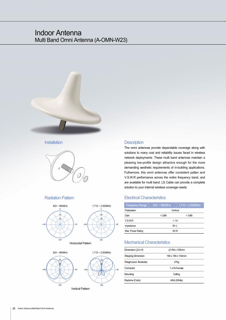
Indoor AntennaMulti Band Omni Antenna (A-OMN-W23)
Indoor Antenna (Multi Band Omni Antenna)26
DescriptionThe omni antennas provide dependable coverage along with
solutions to many cost and reliability issues faced in wireless
network deployments. These multi band antennas maintain a
pleasing low-profile design attractive enough for the more
demanding aesthetic requirements of in-building applications.
Futhemore, this omni antennas offer consistent patten and
V.S.W.R performance across the entire frequency band, and
are available for multi band. LS Cable can provide a complete
solution to your internal wireless coverage needs.
Ø184 x 105mm
190 x 190 x 154mm
270g
1 x N-Female
Ceiling
ASA (White)
Dimension (Øx H)
Shipping Dimension
Weight (excl. Brackets)
Connector
Mounting
Radome (Color)
Electrical Characteristics
Polarization Vertical
Gain > 2dBi > 3dBi
V.S.W.R < 1.6
Impedance 50 Ω
Max. Power Rating 50 W
824 ~ 960MHz 1,710 ~ 2,500MHzFrequency Range
Mechanical Characteristics
824 ~ 960MHz 1,710 ~ 2,500MHz
Horizontal Pattern
824 ~ 960MHz 1,710 ~ 2,500MHz
Vertical Pattern
Installation
Radiation Pattern
Indoor Antenna (Dual Band Patch Antenna) 27
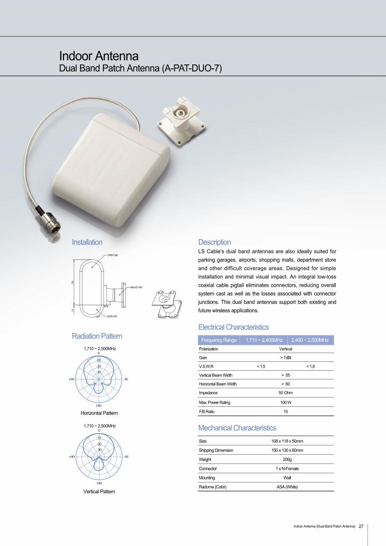
Indoor AntennaDual Band Patch Antenna (A-PAT-DUO-7)
108 x 118 x 50mm
150 x 130 x 60mm
200g
1 x N-Female
Wall
ASA (White)
Size
Shipping Dimension
Weight
Connector
Mounting
Radome (Color)
Electrical Characteristics
Polarization Vertical
Gain > 7dBi
V.S.W.R < 1.5 < 1.8
Vertical Beam Width > 55
Horizontal Beam Width > 60
Impedance 50 Ohm
Max. Power Rating 100 W
F/B Ratio 15
1,710 ~ 2,400MHz 2,400 ~ 2,500MHzFrequency Range
Mechanical Characteristics
DescriptionLS Cable's dual band antennas are also ideally suited for
parking garages, airports, shopping malls, department store
and other difficult coverage areas. Designed for simple
installation and minimal visual impact. An integral low-loss
coaxial cable pigtail eliminates connectors, reducing overall
system cast as well as the losses associated with connector
junctions. This dual band antennas support both existing and
future wireless applications.
1,710 ~ 2,500MHz
Horizontal Pattern
1,710 ~ 2,500MHz
Vertical Pattern
Installation
Radiation Pattern
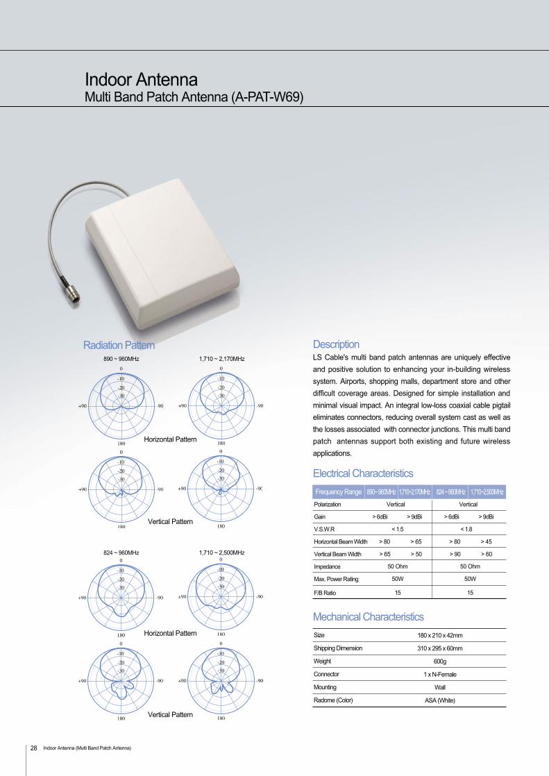
Indoor AntennaMulti Band Patch Antenna (A-PAT-W69)
Indoor Antenna (Multi Band Patch Antenna)28
DescriptionLS Cable's multi band patch antennas are uniquely effective
and positive solution to enhancing your in-building wireless
system. Airports, shopping malls, department store and other
difficult coverage areas. Designed for simple installation and
minimal visual impact. An integral low-loss coaxial cable pigtail
eliminates connectors, reducing overall system cast as well as
the losses associated with connector junctions. This multi band
patch antennas support both existing and future wireless
applications.
180 x 210 x 42mm
310 x 295 x 60mm
600g
1 x N-Female
Wall
ASA (White)
Size
Shipping Dimension
Weight
Connector
Mounting
Radome (Color)
Electrical Characteristics
Polarization Vertical Vertical
Gain > 6dBi > 9dBi > 6dBi > 9dBi
V.S.W.R < 1.5 < 1.8
Horizontal Beam Width > 80 > 65 > 80 > 45
Vertical Beam Width > 65 > 50 > 90 > 60
Impedance
Max. Power Rating
F/B Ratio
50 Ohm
50W
15
50 Ohm
50W
15
Frequency Range
Mechanical Characteristics
890~ 960MHz 1,710~2,170MHz 824 ~ 960MHz 1,710~2,500MHz
824 ~ 960MHz 1,710 ~ 2,500MHz
Horizontal Pattern
Vertical Pattern
890 ~ 960MHz 1,710 ~ 2,170MHz
Horizontal Pattern
Vertical Pattern
Radiation Pattern
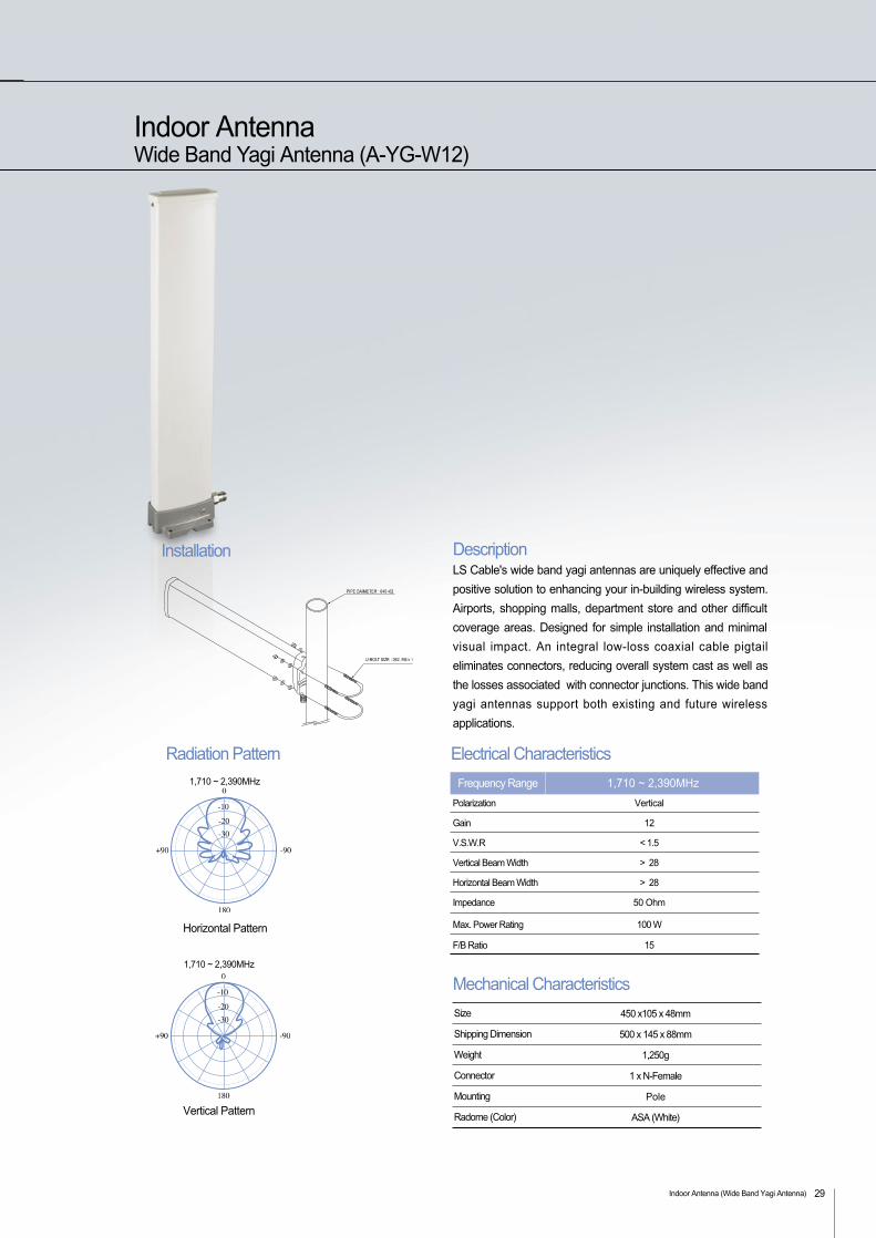
Indoor AntennaWide Band Yagi Antenna (A-YG-W12)
DescriptionLS Cable's wide band yagi antennas are uniquely effective and
positive solution to enhancing your in-building wireless system.
Airports, shopping malls, department store and other difficult
coverage areas. Designed for simple installation and minimal
visual impact. An integral low-loss coaxial cable pigtail
eliminates connectors, reducing overall system cast as well as
the losses associated with connector junctions. This wide band
yagi antennas support both existing and future wireless
applications.
450 x105 x 48mm
500 x 145 x 88mm
1,250g
1 x N-Female
Pole
ASA (White)
Size
Shipping Dimension
Weight
Connector
Mounting
Radome (Color)
Mechanical Characteristics
Installation
Indoor Antenna (Wide Band Yagi Antenna) 29
Electrical Characteristics
Polarization Vertical
Gain 12
V.S.W.R < 1.5
Vertical Beam Width > 28
Horizontal Beam Width > 28
Impedance 50 Ohm
Max. Power Rating 100 W
F/B Ratio 15
1,710 ~ 2,390MHzFrequency Range1,710 ~ 2,390MHz
Horizontal Pattern
1,710 ~ 2,390MHz
Vertical Pattern
Radiation Pattern
![Z[PJH - it.yamaha.com · I_j_^ih^kh_^bg_gb_f]blZjudijhp_kkhjm$* 6WRPSm[_^bl_kv\lhf qlhnmgdpbybklhqgbdZ %HYRU6LHGLH*LWDUUHDQVFKOLH HQ VFKDOWHQ6LHGHQ$* …](https://static.fdocuments.in/doc/165x107/5c8b2a5909d3f21b168bc5a9/zpjh-it-ijihkhbggbfblzjudijhpkkhjm-6wrpsmblkvlhf-qlhnmgdpbybklhqgbdz.jpg)