Transmission and Storage Operations - US EPA · Transmission and Storage Operations XperSEAL...
18
Transmission and Storage Operations XperSEAL Packing System Installation Belle River Mills Compressor Station Cooper-Bessemer GMVC-12 Mary Savalle, PMP, LSSGB Senior Compression Reliability Engineer November 18, 2015
Transcript of Transmission and Storage Operations - US EPA · Transmission and Storage Operations XperSEAL...

Transmission and Storage Operations
XperSEAL Packing System InstallationBelle River Mills Compressor Station
Cooper-Bessemer GMVC-12
Mary Savalle, PMP, LSSGBSenior Compression Reliability EngineerNovember 18, 2015
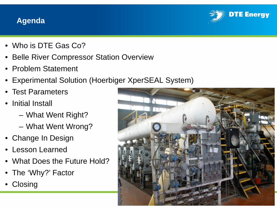
Agenda
• Who is DTE Gas Co?• Belle River Compressor Station Overview• Problem Statement• Experimental Solution (Hoerbiger XperSEAL System)• Test Parameters• Initial Install
– What Went Right?– What Went Wrong?
• Change In Design• Lesson Learned• What Does the Future Hold?• The ‘Why?’ Factor• Closing
2
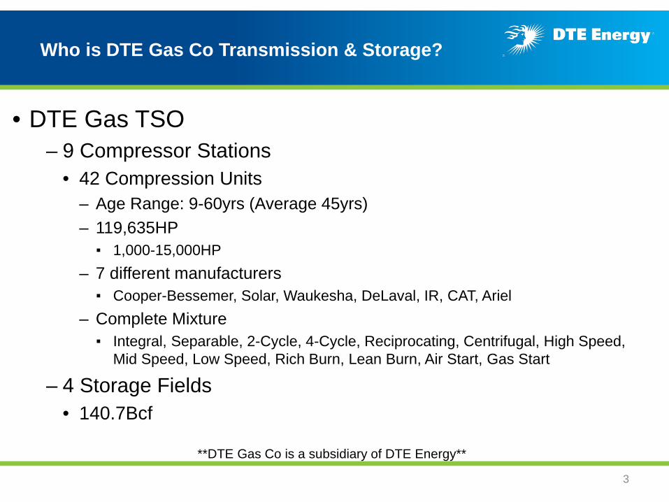
Who is DTE Gas Co Transmission & Storage?
• DTE Gas TSO– 9 Compressor Stations
• 42 Compression Units– Age Range: 9-60yrs (Average 45yrs)– 119,635HP▪ 1,000-15,000HP
– 7 different manufacturers▪ Cooper-Bessemer, Solar, Waukesha, DeLaval, IR, CAT, Ariel
– Complete Mixture▪ Integral, Separable, 2-Cycle, 4-Cycle, Reciprocating, Centrifugal, High Speed,
Mid Speed, Low Speed, Rich Burn, Lean Burn, Air Start, Gas Start
– 4 Storage Fields• 140.7Bcf
**DTE Gas Co is a subsidiary of DTE Energy**
3

Belle River Compressor Station Overview
DTE Gas Belle River Mills Compressor Station
• Largest DTE Gas Storage Facility– 61.9Bcf
• Home to 6 Natural Gas Compression Units Totaling 40,000HP– (1) Cooper-Bessemer GMVC-6 (1,000HP)– (2) Cooper-Bessemer GMVC-12 (2,000HP)– (2) Cooper-Bessemer Z330-16 (10,000HP)– (1) Solar Mars-100 (15,000HP)
• Customers– DTE Gas Customers– Vector, Union, Great Lakes, ANR
• Delivery Capabilities– Capable of flowing over 1Bcf/day on peak days
• Pipeline Pressure Ranges– Storage field pressures range from 230psig to 1550psig
4

Problem Statement
• Methane release quantification and remediation has become a main focal point within DTE Energy. Initiatives have been ongoing which include developing a standard procedure around monitoring methane leaks and experimenting with industry technologies to reduce leakage rates.
• Methane Release – Three Main Areas– Rod Packing Leaks**– High Pressure Valve Leaks– Pressure Control Procedure Blowdowns
• Goal– Minimizing leak rates to become 1st Quartile
• Measure of Success– Implementation of a sustainable program resulting in achievement of planned leak rate
reduction
5

Problem Statement - Rod Packing Leak Reduction
• Compressor Configuration– Leakage is inherent in all reciprocating
compressors
– Compressor rod seals require designed clearances to allow for independent rod and piston motion• Acceptable industry standards sit around
10-12scfh/cylinder, but no formal “standards” have been set by the EPA.
– They are often shut down, but required to remain in operational, pressurized condition• Static vs Dynamic
– Rod seals utilize cylinder pressure to activate the packing rings• DTE operational variations range between
200psi to 1350psi suction pressure
6

Problem Statement - Rod Packing Leak Reduction
• Sealing Technologies– Standard Packing (Current acceptable standard at 10-12scfh/cyl in dynamic mode with new
packing)– Low Emission Packing (Expecting to see up to 60% reduction in dynamic modes)– Zero Emission Packing (Expecting to see minimal to none in static or dynamic mode)
• Rates are dependent on rod size, mechanical wear, operating pressures, gas comp– PM & PdM– What are you pumping?
• Compressor Packing Leakage Paths– Around the gasket or between gland components
▪ Gaskets are critical**– Around worn seal and inner gland faces– Down a worn rod
7

Experimental Solution – Hoerbiger XperSEAL
What is XperSEAL??• Rod Sealing System for reciprocating compressors• System utilizes a pressurized oil barrier to prevent gas leakage through the packing• System made up of three major components
– XperSeal Packing– Hydraulic Unit– PLC (Existing or New)
8
Hydraulic UnitXperSEAL Packing

Experimental Solution – Hoerbiger XperSeal
How Does XperSEAL Work??• Utilization of a hydraulic oil system
– poil>psuction gas
• Utilization of specialized packing set
9
pcyl
HOERBIGER oil barrier seals
poil-in
oil wiper
oil recovery
dynamic gas seals
buffer volume
poil-out

Test Parameters
• Experimental Unit – Belle River Mills GMVC-12
• Unit Description– Low Speed, Reciprocating, 2-Stroke, Integral Machine– 300RPM / 2000HP– 12 Cylinder / 6 Compressor Configuration– Compressor Rod Size – 3”, Single Stage– Installed in 1968– Runtime Hours (As of 12/1/14) – 56,532hrs
• Why This Unit?– Operating Range!
• Suction Pressures – 200psig to 1350psig• Discharge Pressures – 600psig to 1550psig
– Unit Availability!• Unit runs on average 4300hrs/year (Avg over past 4 years)• Unit is only blowdown <1000hrs/year, otherwise unit is in stand-by pressurized mode
10

Initial Installation
• XperSeal Installed December 2014• Installation Timing – 2 weeks• Initial Results
– ZERO leakage in standby pressurized mode– 0.17scfm leakage in operating mode (1.7scfh per cylinder)
11

What Went Right?
• Installation was within schedule and budget
• Initial results proved ideal in standby pressurized mode
• Initial results showed significant improvement in leakage in operating mode– Lowest reads taken 4/8/15 & 5/19/15 at .02scfm or 0.2scfh per cylinder
12

What Went Wrong?
• Hydraulic Unit Failure– Set screw came loose and caused the fan to drop resulting damage fan housing
and blades– Availability of parts– Unit offsite for almost 6 weeks
• Oil Consumption– Occurs when system is on and Unit is operating
• Oil consumption equal or less than typical packing lubrication rates is the performance target– Why is the compressor consuming oil?– Where is the oil going?
• Oil Gain – Occurs when system is off and Unit is operating– Where is the oil coming from?
13

Change In Design
• August 2015– Run Time Hours – 59,454hrs– Total down time – 5 days w/operational lockout/return to service procedures
• What was done?– Total deconstruction of compressor assemblies– Rods checked for roughness– Packing cases were rebuilt with revised rod rings
• What was changed?– Flow meters were installed – Thermocouples installed on each cylinder to show oil temp at the
packing surface– Modifications to the packing configuration were made
• Oil barrier seal ring geometry, removal of auxiallary cylinder side oilbarrier and addition of additional gas sealing ring group
• Results– Continue to see zero leakage in standby pressurized mode– Leak rates increased to .41scfm or 4.1scfh per cylinder – Gasket could be contributing to the leakage!– Oil consumption reduced, but unit still consuming more than expected– Hydraulic unit still fills when system is off and unit is operating
14
Lesson Learned
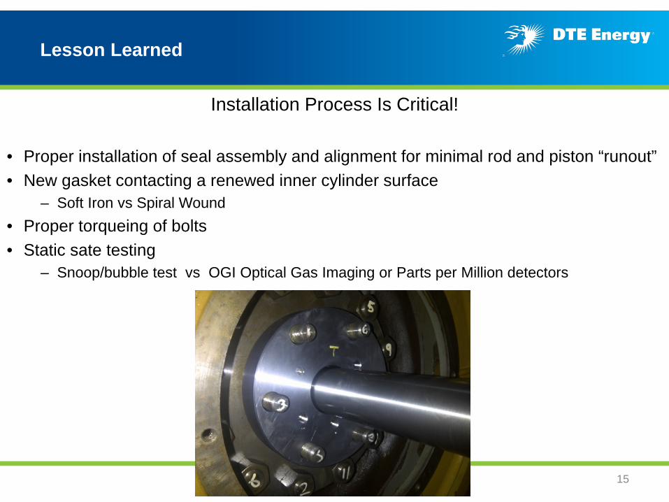
Installation Process Is Critical!
• Proper installation of seal assembly and alignment for minimal rod and piston “runout”• New gasket contacting a renewed inner cylinder surface
– Soft Iron vs Spiral Wound• Proper torqueing of bolts• Static sate testing
– Snoop/bubble test vs OGI Optical Gas Imaging or Parts per Million detectors
15

What does the future hold?
• DTE Gas intends to continue experimentation of this system with Hoerbiger– Unit overhaul scheduled for summer 2016
• Packing will be revisited and analyzed prior to new design being installed
• Standby Pressurized System installed on Z330 unit at the same station– Unit Description
• Low Speed, Reciprocating, 2-Stroke, Integral Machine• 330RPM / 10,000HP• 16 Cylinder / 8 Compressor Config (Only 4 in operation at one time) • Compressor Rod Size – 4.75”, Single Stage• Installed in 1972• Runtime Hours (As of 9/30/2015) – 124,242hrs
– Expected commissioning and results February 2016– Opportunity for significant annual savings and reduction
of lost gas
16
The ‘Why?’ Factor
• Why continue experimentation after experiencing issues?– It worked!
• ZERO in standby pressurized• As low as .2scfh/cylinder
• Why is this important?– Prior to this installation, largest rod size tested was 2.5” – Although installed on 12 applications, this test has the highest suction pressures– Great test case for real life Transmission and Storage applications
If we can make this successful, DTE will have a great start to minimizing the amount of methane released by the compression fleet. This allows for reduction in lost gas,
adherence to any rulings that may come down and allow for the Legacy Units in the fleet to remain compliant.
17

• DTE Gas TSO Operations is continually looking for ways to upgrade our system and all equipment within
• We look forward to input, feedback and recommendations on all items mentioned
• Any follow up inquiries:– Mary Savalle
• [email protected]• 586-707-4652
QUESTIONS??18
Closing