Transmission and Distribution of Electrical Powerafguven.com/depo/dersnot/esm301/not2.pdf ·...
33
Dr Houssem Rafik El Hana Bouchekara 1 Transmission and Distribution of Electrical Power Dr : Houssem Rafik El- Hana BOUCHEKARA 2009/2010 1430/1431 KINGDOM OF SAUDI ARABIA Ministry Of High Education Umm Al-Qura University College of Engineering & Islamic Architecture Department Of Electrical Engineering
Transcript of Transmission and Distribution of Electrical Powerafguven.com/depo/dersnot/esm301/not2.pdf ·...
Dr Houssem Rafik El Hana Bouchekara 1
Transmission and Distribution of
Electrical Power
Dr : Houssem Rafik El- Hana BOUCHEKARA
2009/2010 1430/1431
KINGDOM OF SAUDI ARABIA Ministry Of High Education
Umm Al-Qura University College of Engineering & Islamic Architecture
Department Of Electrical Engineering
Dr Houssem Rafik El Hana Bouchekara 2
1.1 INTRODUCTION ............................................................................................................... 3
1.2 CABLES CONSTRUCTION .................................................................................................... 5
1.2.1 Conductors ............................................................................................................ 6
1.2.2 Insulation ............................................................................................................... 7
1.3 TYPES OF CABLES............................................................................................................. 8
1.3.1 Transmission cables ............................................................................................... 9 1.3.1.1 Self Contained Liquid-Filled (SCLF) Cables.................................................................... 9 1.3.1.1 Figure 3: Self Contained Liquid-Filled (SCLF) Cables ................................................... 10 1.3.1.2 High Pressure Liquid-Filled Pipe-Type Cables (HPLF) ................................................. 11 1.3.1.3 Solid Dielectric Cables ................................................................................................ 13 1.3.1.4 Submarine Cables....................................................................................................... 14
1.3.2 Medium voltage power cable .............................................................................. 14 1.3.2.1 Teck Cables ................................................................................................................ 15 1.3.2.2 Shielded Cables .......................................................................................................... 16 1.3.2.3 Concentric Neutral Cables .......................................................................................... 16 1.3.2.4 Paper-Insulated Lead-Covered Cables (PILC) ............................................................. 17 1.3.2.5 Submarine Cables....................................................................................................... 18 1.3.2.6 Mining Cables ............................................................................................................. 19 1.3.2.7 Aluminum-Sheathed Cables ....................................................................................... 20
1.3.3 Direct Current Cables ........................................................................................... 20
1.3.4 Superconduction .................................................................................................. 20
1.4 ELECTRICAL CHARACTERISTICS OF INSULATED CABLES ............................................................ 21
1.4.1 Electric stress in Single Conductor Cable ............................................................. 21
1.4.2 Capacitance of Single conductor Cable ............................................................... 25
1.4.3 Dielectric constant of cable insulation ................................................................ 26
1.4.4 Charging current ................................................................................................. 27
1.4.5 Determination of insulation resistance of single conductor cable ...................... 27
1.4.6 Dielectric power factor and dielectric loss ........................................................... 29
1.5 LOCATION OF FAULTS IN UNDERGROUND CABLES ................................................................. 33
Dr Houssem Rafik El Hana Bouchekara 3
1.1 INTRODUCTION
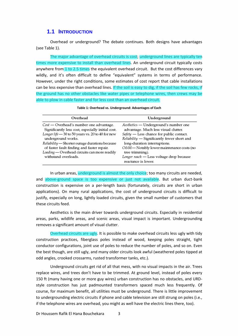
Overhead or underground? The debate continues. Both designs have advantages
(see Table 1).
The major advantage of overhead circuits is cost; underground lines are typically ten
times more expensive to install than overhead lines. An underground circuit typically costs
anywhere from 1 to 2.5 times the equivalent overhead circuit. But the cost differences vary
wildly, and it’s often difficult to define “equivalent” systems in terms of performance.
However, under the right conditions, some estimates of cost report that cable installations
can be less expensive than overhead lines. If the soil is easy to dig, if the soil has few rocks, if
the ground has no other obstacles like water pipes or telephone wires, then crews may be
able to plow in cable faster and for less cost than an overhead circuit.
Table 1: Overhead vs. Underground: Advantages of Each
In urban areas, underground is almost the only choice; too many circuits are needed,
and above-ground space is too expensive or just not available. But urban duct-bank
construction is expensive on a per-length basis (fortunately, circuits are short in urban
applications). On many rural applications, the cost of underground circuits is difficult to
justify, especially on long, lightly loaded circuits, given the small number of customers that
these circuits feed.
Aesthetics is the main driver towards underground circuits. Especially in residential
areas, parks, wildlife areas, and scenic areas, visual impact is important. Undergrounding
removes a significant amount of visual clutter.
Overhead circuits are ugly. It is possible to make overhead circuits less ugly with tidy
construction practices, fiberglass poles instead of wood, keeping poles straight, tight
conductor configurations, joint use of poles to reduce the number of poles, and so on. Even
the best though, are still ugly, and many older circuits look awful (weathered poles tipped at
odd angles, crooked crossarms, rusted transformer tanks, etc.).
Underground circuits get rid of all that mess, with no visual impacts in the air. Trees
replace wires, and trees don’t have to be trimmed. At ground level, instead of poles every
150 ft (many having one or more guy wires) urban construction has no obstacles, and URD-
style construction has just padmounted transformers spaced much less frequently. Of
course, for maximum benefit, all utilities must be underground. There is little improvement
to undergrounding electric circuits if phone and cable television are still strung on poles (i.e.,
if the telephone wires are overhead, you might as well have the electric lines there, too).
Davut
Highlight
Davut
Highlight
Davut
Highlight
Davut
Highlight
Davut
Highlight
Davut
Highlight
Davut
Highlight

Dr Houssem Rafik El Hana Bouchekara 4
Figure 1: Before and After: Left, part of the Yonge Street hill, Toronto, August, 1947; and Right, the same location as it looked 44 years later in August, 1991.
While underground circuits are certainly more appealing when finished, during
installation construction is messier than overhead installation. Lawns, gardens, sidewalks,
and driveways are dug up; construction lasts longer; and the installation “wounds” take time
to heal. These factors don’t matter much when installing circuits into land that is being
developed, but it can be upsetting to customers in an existing, settled community.
Underground circuits are more reliable. Overhead circuits typically fault about 90
times/100 mi/year; underground circuits fail less than 10 times/ 100 mi/year. Because
overhead circuits have more faults, they cause more voltage sags, more momentary
interruptions, and more long-duration interruptions.
Even accounting for the fact that most overhead faults are temporary, overhead
circuits have more permanent faults that lead to long-duration circuit interruptions. The one
disadvantage of underground circuits is that when they do fail, finding the failure is harder,
and fixing the damage or replacing the equipment takes longer. This can partially be avoided
by using loops capable of serving customers from two directions, by using conduits for faster
replacement, and by using better fault location techniques.
Underground circuits are much less prone to the elements. A major hurricane may
drain an overhead utility’s resources, crews are completely tied up, customer outages
become very long, and cleanup costs are a major cost to utilities. However, underground
circuits are not totally immune from the elements. In “heat storms,” underground circuits
are prone to rashes of failures. Underground circuits have less overload capability than
overhead circuits; failures increase with operating temperature.
In addition to less storm cleanup, underground circuits require less periodic
maintenance. Underground circuits don’t require tree trimming, easily the largest fraction of
most distribution operations and maintenance budgets.
The CEA (1992) estimated that underground system maintenance averaged 2% of
system plant investment whereas overhead systems averaged 3 to 4%, or as much as twice
that of underground systems.
Davut
Highlight
Davut
Highlight
Davut
Highlight
Davut
Highlight
Dr Houssem Rafik El Hana Bouchekara 5
Underground circuits are safer to the public than overhead circuits. Overhead
circuits are more exposed to the public. Kites, ladders, downed wires, truck booms —
despite the best public awareness campaigns, these still expose the public to electrocution
from overhead lines. Don’t misunderstand; underground circuits still have dangers, but
they’re much less than on overhead circuits. For the public, dig-ins are the most likely source
of contact.
For utility crews, both overhead and underground circuits offer dangers that proper
work practices must address to minimize risks.
We cannot assume that underground infrastructure will last as long as overhead
circuits. Early URD systems failed at a much higher rate than expected. While most experts
believe that modern underground equipment is more reliable, it is still prudent to believe
that an overhead circuit will last 40 years, while an underground circuit will only last 30
years.
Overhead vs. underground is not an all or nothing proposition. Many systems are
hybrids; some schemes are:
1. Overhead mainline with underground taps — The larger, high-current
conductors are overhead. If the mains are routed along major roads, they have
less visual impact. Lateral taps down side roads and into residential areas, parks,
and shopping areas are underground. Larger primary equipment like regulators,
reclosers, capacitor banks, and automated switches are installed where they are
more economical — on the overhead mains. Because the mainline is a major
contributor to reliability, this system is still less reliable than an all-underground
system.
2. Overhead primary with underground secondary — Underground secondary
eliminates some of the clutter associated with overhead construction.
Eliminating much of the street and yard crossings keeps the clutter to the pole-
line corridor. Costs are reasonable because the primary-level equipment is still
all overhead.
Converting from overhead to underground is costly, yet there are locations and
situations where it is appropriate for utilities and their customers. Circuit extensions, circuit
enhancements to carry more load, and road-rebuilding projects — all are opportunities for
utilities and communities to upgrade to underground service.
1.2 CABLES CONSTRUCTION
Cables are used for the transmission and distribution of electrical energy in public
and industrial power systems. Cables are generally classified as underground, submarine or
aerial.
The permissible loading of the cables is determined by different parameters such as
environmental conditions, type of laying (in ground or in air), cable design and type of
insulation, operating conditions and so on.
Conductors are made of aluminum or copper.
Davut
Highlight
Davut
Highlight
Davut
Highlight
Davut
Highlight
Davut
Highlight
Davut
Highlight
Davut
Highlight
Davut
Sticky Note
Havai
Dr Houssem Rafik El Hana Bouchekara 6
The insulation is of various materials; PVC (polyvinyl chloride) and PE (polyethylene)
are used as standard used in LV and MV cables; oil - insulation and gas - pressure cables can
still be found in HV systems (𝑈𝑛 > 110 kV), whereas XLPE (cross - linked polyethylene) -
insulated cables are today standard in power systems with nominal voltages of 110 kV and
above. Mass -impregnated paper - insulated cables are still in use in the medium - voltage
range, but are found only on older cable routes; this type will no longer be installed.
Cable abbreviation codes are used that indicate the material of the cable from the
inner layer to outer layers. Copper conductors, mass - impregnated paper – insulated cables,
and internal protection shields are not specially indicated. In addition to the coding of the
inner construction, the number of conductors, the cross - section and the shape of the
conduct as well as the nominal voltage (line - to - ground / line - to - line) is indicated.
1.2.1 CONDUCTORS
The fundamental concern of power cable engineering is to transmit current (power)
economically and efficiently. The choice of the conductor material, size, and design must
take into consideration such items as:
Ampacity (current carrying capacity)
Voltage stress at the conductor
Voltage regulation
Conductor losses
Bending radius and flexibility
Overall economics
Material considerations
Mechanical properties
The conductors used in underground cables can be copper or aluminum. Aluminum
dictates larger conductor sizes to carry the same current as copper. The need for mechanical
flexibility requires stranded conductors to be used. The equivalent aluminum cable is lighter
in weight and larger in diameter in comparison to copper cable. Stranded conductors can be
in various configurations, for example:
1. Concentric round
2. Compressed round (97% of the diameter of concentric)
3. Compact round (90–91% of the diameter of concentric)
4. Rope
5. Abbreviation
The metal type and size determines the ampacity and losses (𝐼2𝑅). Copper having a
higher intrinsic conductivity will have a greater ampacity and lower resistance than an
equivalent size aluminum conductor. Aluminum 1350 alloy medium hardness is typical for
power cable use.
Davut
Highlight
Davut
Highlight
Davut
Highlight
Davut
Highlight
Davut
Highlight
Davut
Highlight
Davut
Highlight
Davut
Highlight
Davut
Highlight
Davut
Highlight
Davut
Highlight
Dr Houssem Rafik El Hana Bouchekara 7
1.2.2 INSULATION
Within the low voltage range, PVC or PE insulated cables with an outer protective
covering or sheath of PVC are used.
For increased protection against touch voltages, concentric copper screens of round
wires are applied to the insulation. If waveform screens are applied, the screen must not be
cut for connecting coupling T - joints (cable type NYCWY). For higher tensile strength, cables
with longitudinal galvanized steel wires as outer armoring are used (cable type NYFGY). To
protect cables against penetration of aromatic hydrocarbons, a lead alloy sheath is used
covered by the outer sheath of PVC (cable type NYKY).
Within the medium - voltage range (3.6/6 kV to 18/30 kV), cables without electric
field limiting screens can still be used, as the inhomogeneous field causes relatively low
electric field strength in the tangential direction in the insulation.
For higher voltages, only cables with homogeneous electric field are used. An
electric field - limiting screen or foil ensures a homogeneous electric field in the
dielectricum; the electric field strength is only effective in the radial direction.
Each cable core is covered with its own sheath of lead alloy. To protect the sheath
against mechanical damage, additional armoring by steel tapes or wires is used (cable type
NEKEBA).
Today cables with plastic insulation (PVC, PE or XLPE) are used in the medium -
voltage range, whereas PVC insulations are used only for voltages up to 10 kV due to the
high dissipation factor (cable type NYSEY).
XLPE insulation (cable type N2XS2Y) is used for higher voltages (110 kV and above).
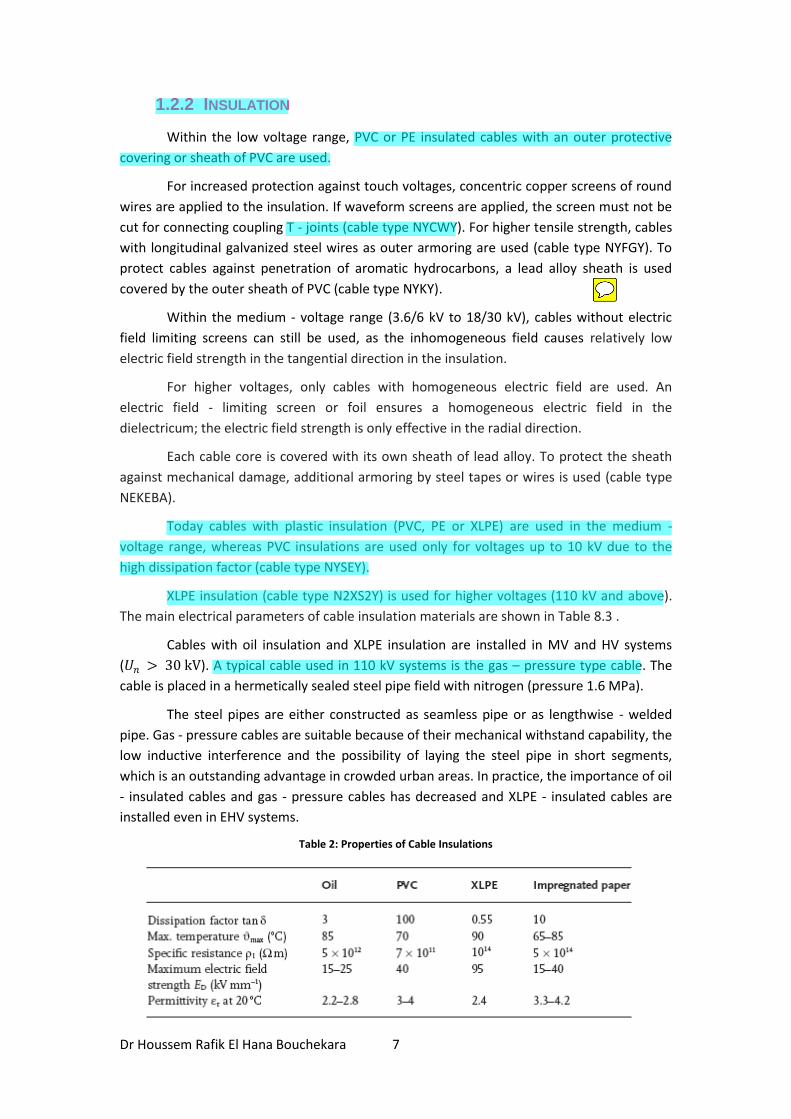
The main electrical parameters of cable insulation materials are shown in Table 8.3 .
Cables with oil insulation and XLPE insulation are installed in MV and HV systems
(𝑈𝑛 > 30 kV). A typical cable used in 110 kV systems is the gas – pressure type cable. The
cable is placed in a hermetically sealed steel pipe field with nitrogen (pressure 1.6 MPa).
The steel pipes are either constructed as seamless pipe or as lengthwise - welded
pipe. Gas - pressure cables are suitable because of their mechanical withstand capability, the
low inductive interference and the possibility of laying the steel pipe in short segments,
which is an outstanding advantage in crowded urban areas. In practice, the importance of oil
- insulated cables and gas - pressure cables has decreased and XLPE - insulated cables are
installed even in EHV systems.
Table 2: Properties of Cable Insulations
Davut
Highlight
Davut
Highlight
Davut
Highlight
Davut
Sticky Note
kılıf
Davut
Highlight
Davut
Highlight
Davut
Highlight
Dr Houssem Rafik El Hana Bouchekara 8
Some of the key properties of cable insulation are:
1. Dielectric constant (e, also called permittivity) — This determines the cable’s
capacitance: the dielectric constant is the ratio of the capacitance with the
insulation material to the capacitance of the same configuration in free space.
Cables with higher capacitance draw more charging current.
2. Volume resistivity —Current leakage through the insulation is a function of the
insulation’s dc resistivity. Resistivity decreases as temperature increases.
Modern insulation has such high resistivity that very little resistive current
passes from the conductor through the insulation.
3. Dielectric losses —Like a capacitor, a cable has dielectric losses. These losses are
due to dipole movements within the polymer or by the movement of charge
carriers within the insulation. Dielectric losses contribute to a cable’s resistive
leakage current. Dielectric losses increase with frequency and temperature and
with operating voltage.
4. Dissipation factor (also referred to as the loss angle, loss tangent, tan d, and
approximate power factor) — The dissipation factor is the ratio of the resistive
current drawn by the cable to the capacitive current drawn (IR/IX). Because the
leakage current is normally low, the dissipation factor is approximately the same
as the power factor:
1.3 TYPES OF CABLES
In the field of underground wiring, by the time that the polyphase AC system was
conceived in 1886, several major steps had been taken towards making possible a practical
underground power transmission system. One was Borel's invention of an efficient lead
press in 1879, and another was MacCracken's concept of helically applied paper insulating
tapes in 1884. Finally, in 1890, Vincent de Ferranti produced his famous 10,000-volt
concentric cable, which was installed in London, England.
Continuous progress in the development of underground power transmission has
taken place since that time. The first 3-conductor 25 kV cables were installed in Montreal in
1902, and they operated successfully for over 50 years. Then, in 1917, Emanueli conceived a
design for hollow-core oil-filled cables, a breakthrough which permitted eventual
transmission of power at high and extra-high voltages.
Gradually, the voltage levels of underground power cables increased, to 66 kV in
1926 in Montreal and Philadelphia, 220 kV in 1936 in Paris, and in recent years, reaching 525
kV in Canada and 535 kV in the United States. Current technology permits underground
transmission cable systems as high as 1,100 kV.
Davut
Highlight
Davut
Highlight
Davut
Highlight
Davut
Highlight
Davut
Highlight
Davut
Highlight
Davut
Highlight
Davut
Highlight
Davut
Highlight
Dr Houssem Rafik El Hana Bouchekara 9
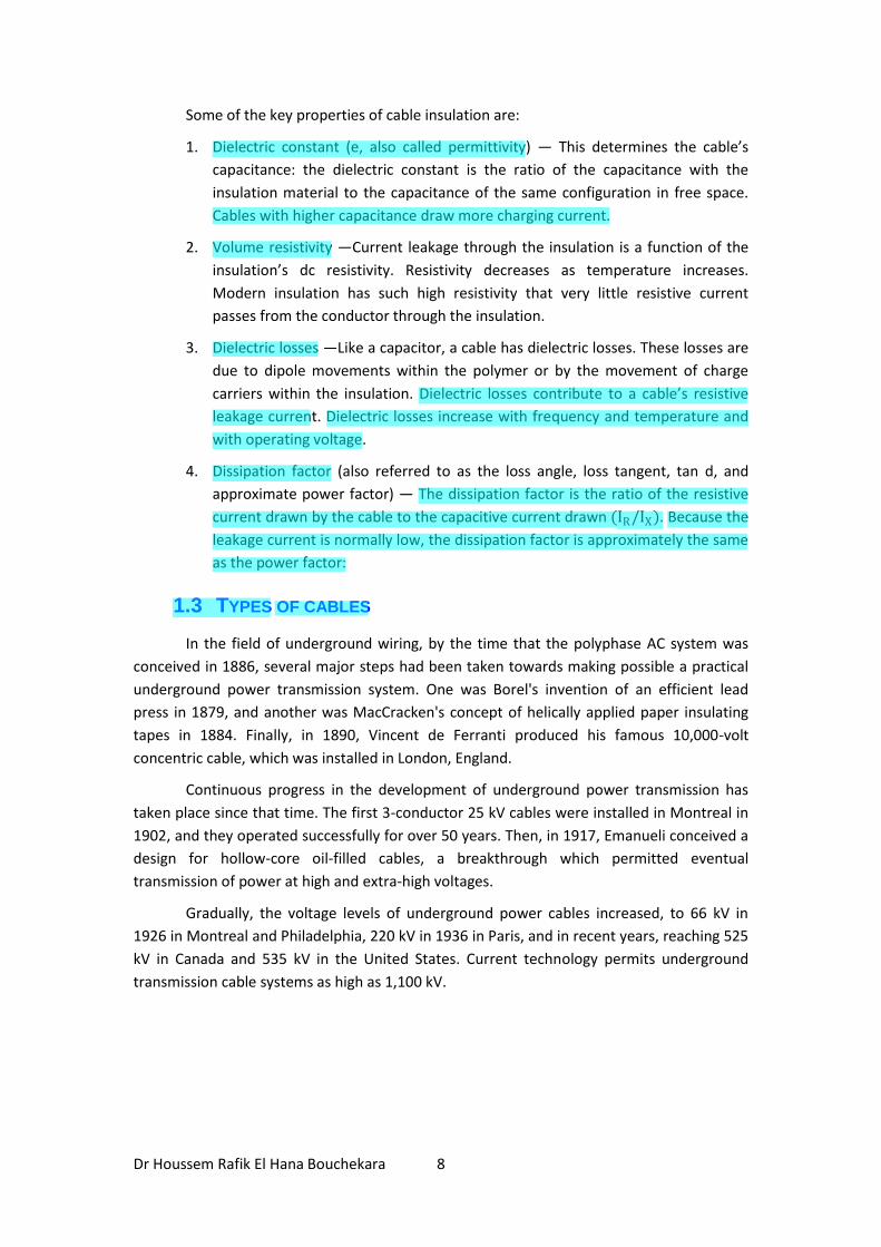
Figure 2: An historic photo of downtown Toronto in 1883, at the peak of overhead chaos.
1.3.1 TRANSMISSION CABLES
1.3.1.1 Self Contained Liquid-Filled (SCLF) Cables
Impregnated paper insulation was first used by Ferranti in a 10 kV cable.
Impregnated paper does not give the impression of being a suitable insulation material.
However, the combination of its excellent electrical and mechanical characteristics has
resulted in a reliable and economic insulation unsurpassed for many decades, and it now
claims a history of almost 100 years. Many paper-insulated circuits dating back to the early
part of this century are still in service. Others that have been replaced by larger cables after
decades of operation, have exhibited excellent insulation integrity when examined in the
laboratory.
The drying and impregnating process for solid and non-pressure type paper cables, leads to
the formation of dielectric (air) voids which ionize under electrical stress. The ionic
bombardment of the liquid and paper can ultimately result in failure. This led Emanueli to
develop the self-contained oil-filled cable which was actually implemented in 1924. The
basic principle of a liquid-filled cable is that all the spaces inside the cable sheath are
completely filled, thus preventing voids in the insulation.
Davut
Highlight
Davut
Highlight
Davut
Sticky Note
emdirilmiş
Davut
Highlight
Davut
Highlight
Dr Houssem Rafik El Hana Bouchekara 10
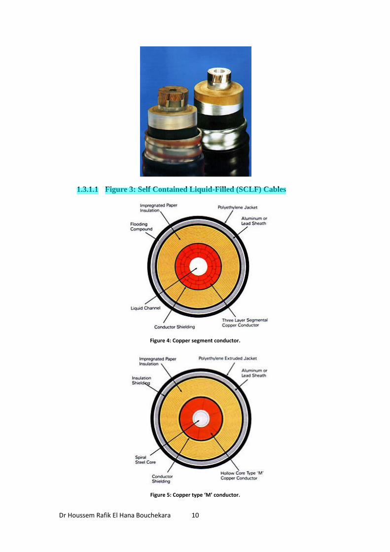
1.3.1.1 Figure 3: Self Contained Liquid-Filled (SCLF) Cables
Figure 4: Copper segment conductor.
Figure 5: Copper type ‘M’ conductor.
Davut
Highlight
Dr Houssem Rafik El Hana Bouchekara 11
Two typical self-contained, single-conductor, liquid-filled cables are shown in Figure
4 and Figure 5. The first has a copper segmented conductor and a hollow core, while the
second has a Milliken, or Type 'M', copper conductor with a spiral steel core.
The manufacturing process starts with the production of the conductor. Segmented
copper conductors, as in Figure 4, may comprise one, two or more layers of segments,
applied one layer at a time from the smallest diameter to the largest. Due to the shape of
the segments, this type of conductor, while having a hollow core, is usually self-supporting
and does not require a central helix to prevent it from collapsing.
With very large conductors, as shown in Figure 5, the Type 'M' construction is used.
This conductor consists of six segments. Each segment is made up of wires stranded and
shaped in the stranding machine, the segments being lightly insulated from one another by
paper tapes. The six segments are cabled over a spiral steel core.
The paper insulation is stored and applied under constant temperature and low
relative humidity conditions in one pass. For a cable of about 220 kV and over, this requires
a machine with many taping heads maintained under uniform temperature, constant
relative humidity and extreme cleanliness conditions.
The insulated cable is placed in a horizontal pan, which in turn, is placed inside the
impregnating tank. The insulation is dried under vacuum, then completely immersed and
impregnated with insulating liquid under pressure. After cooling, the metallic sheath is
applied. Metal sheaths are either a lead alloy or aluminum. They are seamless, and their
integrity is essential.
The sheathed and impregnated cable is provided with a polyethylene (PE) or
polyvinyl chloride (PVC) jacket. From the time the cable is impregnated, it is always
connected to a liquid supply under positive pressure, and as a result, during shipment,
installation, and operation the cable is never permitted to develop voids.
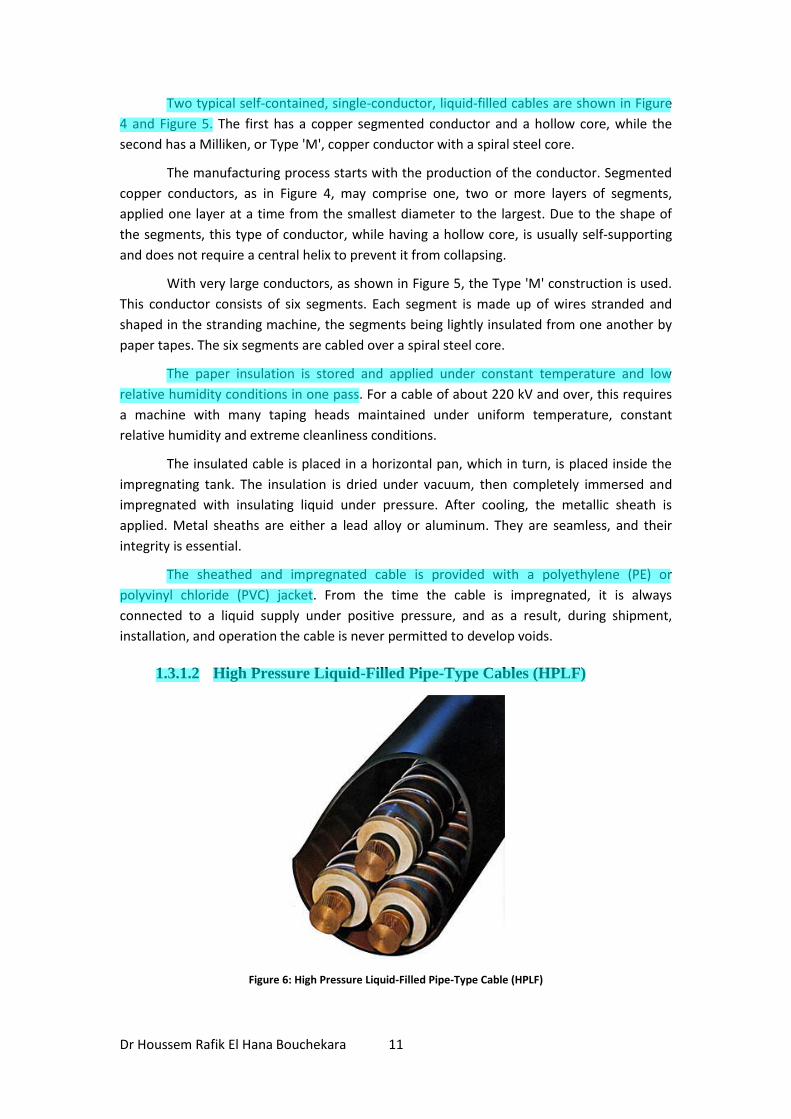
1.3.1.2 High Pressure Liquid-Filled Pipe-Type Cables (HPLF)
Figure 6: High Pressure Liquid-Filled Pipe-Type Cable (HPLF)
Davut
Highlight
Davut
Highlight
Davut
Highlight
Davut
Highlight
Dr Houssem Rafik El Hana Bouchekara 12
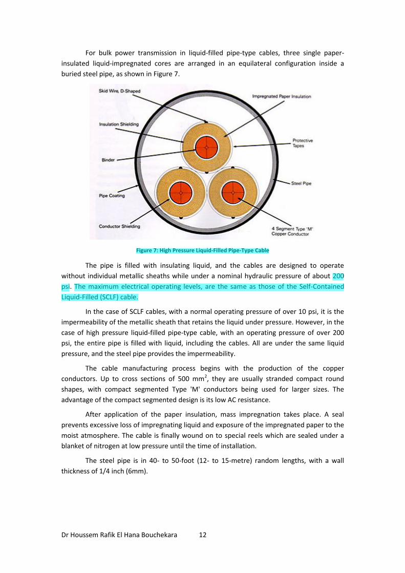
For bulk power transmission in liquid-filled pipe-type cables, three single paper-
insulated liquid-impregnated cores are arranged in an equilateral configuration inside a
buried steel pipe, as shown in Figure 7.
Figure 7: High Pressure Liquid-Filled Pipe-Type Cable
The pipe is filled with insulating liquid, and the cables are designed to operate
without individual metallic sheaths while under a nominal hydraulic pressure of about 200
psi. The maximum electrical operating levels, are the same as those of the Self-Contained
Liquid-Filled (SCLF) cable.
In the case of SCLF cables, with a normal operating pressure of over 10 psi, it is the
impermeability of the metallic sheath that retains the liquid under pressure. However, in the
case of high pressure liquid-filled pipe-type cable, with an operating pressure of over 200
psi, the entire pipe is filled with liquid, including the cables. All are under the same liquid
pressure, and the steel pipe provides the impermeability.
The cable manufacturing process begins with the production of the copper
conductors. Up to cross sections of 500 mm2, they are usually stranded compact round
shapes, with compact segmented Type 'M' conductors being used for larger sizes. The
advantage of the compact segmented design is its low AC resistance.
After application of the paper insulation, mass impregnation takes place. A seal
prevents excessive loss of impregnating liquid and exposure of the impregnated paper to the
moist atmosphere. The cable is finally wound on to special reels which are sealed under a
blanket of nitrogen at low pressure until the time of installation.
The steel pipe is in 40- to 50-foot (12- to 15-metre) random lengths, with a wall
thickness of 1/4 inch (6mm).
Davut
Highlight
Davut
Highlight
Davut
Highlight
Dr Houssem Rafik El Hana Bouchekara 13
Typical nominal pipe sizes for various systems, are as follows:
Internal Diameter System
5" (127 mm) 72 kV
6" (152 mm) 138 kV
8" (203 mm) 230 kV
10" (254 mm) 345 kV
The pipe size chosen is usually the nearest standard size which has an internal area 2.5 or 2.8
times that of the three cables. This amounts to about a 50% fill, which allows ample
installation space without jamming and permits lateral movement of conductors during
electrical load cycles.
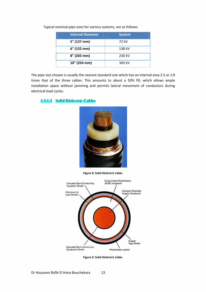
1.3.1.3 Solid Dielectric Cables
Figure 8: Solid Dielectric Cable.
Figure 9: Solid Dielectric Cable.
Davut
Highlight
Dr Houssem Rafik El Hana Bouchekara 14
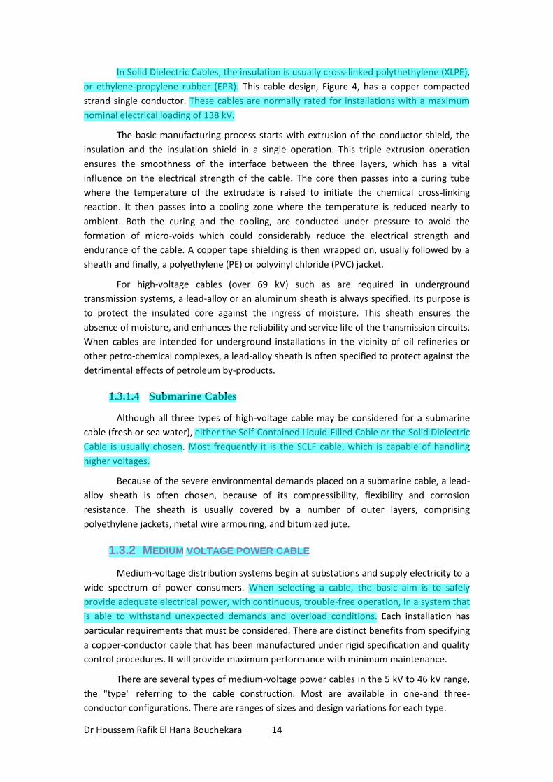
In Solid Dielectric Cables, the insulation is usually cross-linked polythethylene (XLPE),
or ethylene-propylene rubber (EPR). This cable design, Figure 4, has a copper compacted
strand single conductor. These cables are normally rated for installations with a maximum
nominal electrical loading of 138 kV.
The basic manufacturing process starts with extrusion of the conductor shield, the
insulation and the insulation shield in a single operation. This triple extrusion operation
ensures the smoothness of the interface between the three layers, which has a vital
influence on the electrical strength of the cable. The core then passes into a curing tube
where the temperature of the extrudate is raised to initiate the chemical cross-linking
reaction. It then passes into a cooling zone where the temperature is reduced nearly to
ambient. Both the curing and the cooling, are conducted under pressure to avoid the
formation of micro-voids which could considerably reduce the electrical strength and
endurance of the cable. A copper tape shielding is then wrapped on, usually followed by a
sheath and finally, a polyethylene (PE) or polyvinyl chloride (PVC) jacket.
For high-voltage cables (over 69 kV) such as are required in underground
transmission systems, a lead-alloy or an aluminum sheath is always specified. Its purpose is
to protect the insulated core against the ingress of moisture. This sheath ensures the
absence of moisture, and enhances the reliability and service life of the transmission circuits.
When cables are intended for underground installations in the vicinity of oil refineries or
other petro-chemical complexes, a lead-alloy sheath is often specified to protect against the
detrimental effects of petroleum by-products.
1.3.1.4 Submarine Cables
Although all three types of high-voltage cable may be considered for a submarine
cable (fresh or sea water), either the Self-Contained Liquid-Filled Cable or the Solid Dielectric
Cable is usually chosen. Most frequently it is the SCLF cable, which is capable of handling
higher voltages.
Because of the severe environmental demands placed on a submarine cable, a lead-
alloy sheath is often chosen, because of its compressibility, flexibility and corrosion
resistance. The sheath is usually covered by a number of outer layers, comprising
polyethylene jackets, metal wire armouring, and bitumized jute.
1.3.2 MEDIUM VOLTAGE POWER CABLE
Medium-voltage distribution systems begin at substations and supply electricity to a
wide spectrum of power consumers. When selecting a cable, the basic aim is to safely
provide adequate electrical power, with continuous, trouble-free operation, in a system that
is able to withstand unexpected demands and overload conditions. Each installation has
particular requirements that must be considered. There are distinct benefits from specifying
a copper-conductor cable that has been manufactured under rigid specification and quality
control procedures. It will provide maximum performance with minimum maintenance.
There are several types of medium-voltage power cables in the 5 kV to 46 kV range,
the "type" referring to the cable construction. Most are available in one-and three-
conductor configurations. There are ranges of sizes and design variations for each type.
Davut
Highlight
Davut
Highlight
Davut
Highlight
Davut
Highlight
Davut
Highlight
Davut
Highlight
Davut
Highlight
Dr Houssem Rafik El Hana Bouchekara 15
1.3.2.1 Teck Cables
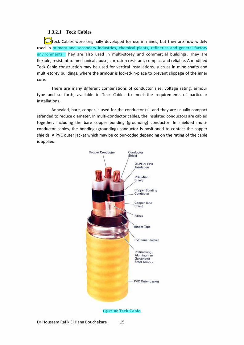
Teck Cables were originally developed for use in mines, but they are now widely
used in primary and secondary industries, chemical plants, refineries and general factory
environments. They are also used in multi-storey and commercial buildings. They are
flexible, resistant to mechanical abuse, corrosion resistant, compact and reliable. A modified
Teck Cable construction may be used for vertical installations, such as in mine shafts and
multi-storey buildings, where the armour is locked-in-place to prevent slippage of the inner
core.
There are many different combinations of conductor size, voltage rating, armour
type and so forth, available in Teck Cables to meet the requirements of particular
installations.
Annealed, bare, copper is used for the conductor (s), and they are usually compact
stranded to reduce diameter. In multi-conductor cables, the insulated conductors are cabled
together, including the bare copper bonding (grounding) conductor. In shielded multi-
conductor cables, the bonding (grounding) conductor is positioned to contact the copper
shields. A PVC outer jacket which may be colour-coded depending on the rating of the cable
is applied.
Figure 10: Teck Cable.
Davut
Sticky Note
Teck-Hughes Gold Mines in Kirkland Lake,. Ontario
Davut
Highlight
Davut
Highlight
Dr Houssem Rafik El Hana Bouchekara 16
1.3.2.2 Shielded Cables
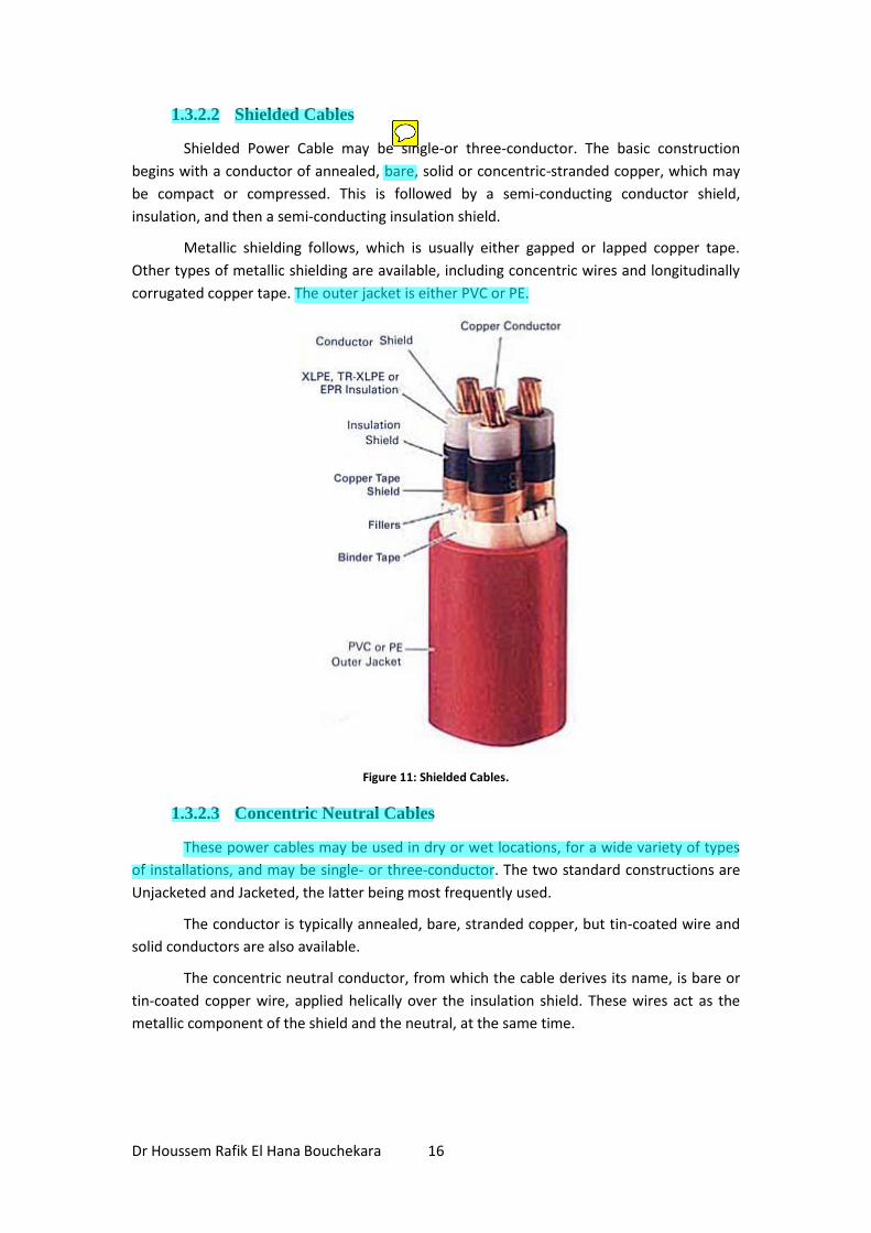
Shielded Power Cable may be single-or three-conductor. The basic construction
begins with a conductor of annealed, bare, solid or concentric-stranded copper, which may
be compact or compressed. This is followed by a semi-conducting conductor shield,
insulation, and then a semi-conducting insulation shield.
Metallic shielding follows, which is usually either gapped or lapped copper tape.
Other types of metallic shielding are available, including concentric wires and longitudinally
corrugated copper tape. The outer jacket is either PVC or PE.
Figure 11: Shielded Cables.
1.3.2.3 Concentric Neutral Cables
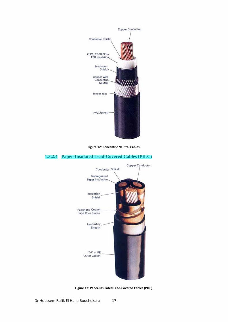
These power cables may be used in dry or wet locations, for a wide variety of types
of installations, and may be single- or three-conductor. The two standard constructions are
Unjacketed and Jacketed, the latter being most frequently used.
The conductor is typically annealed, bare, stranded copper, but tin-coated wire and
solid conductors are also available.
The concentric neutral conductor, from which the cable derives its name, is bare or
tin-coated copper wire, applied helically over the insulation shield. These wires act as the
metallic component of the shield and the neutral, at the same time.
Davut
Highlight
Davut
Sticky Note
çıplak
Davut
Highlight
Davut
Highlight
Davut
Highlight
Davut
Highlight
Dr Houssem Rafik El Hana Bouchekara 17
Figure 12: Concentric Neutral Cables.
1.3.2.4 Paper-Insulated Lead-Covered Cables (PILC)
Figure 13: Paper-Insulated Lead-Covered Cables (PILC).
Davut
Highlight
Dr Houssem Rafik El Hana Bouchekara 18
PILC cables are used in power distribution and industrial applications, and they may
be installed exposed, in underground ducts or directly buried. Their design begins with
annealed, bare copper conductor(s) which may be round, concentric, compressed or
compact stranded, compact sector, and in larger sizes … Type M segmental stranded. An
example of compact sector conductors is shown in the illustration. The insulated cable core
is impregnated with a medium viscosity polybutene-based compound. The combination of
the excellent electrical and mechanical characteristics of the liquid and the paper has
resulted in a reliable and economic insulation, which now claims a history of almost 100
years. It is little wonder why so many utilities and power-consuming industries, still continue
to specify PILC.
To prevent the ingress of moisture, a seamless lead-alloy sheath is applied. The
outer jacket may be PVC or PE, and if required by the application, armour is available.
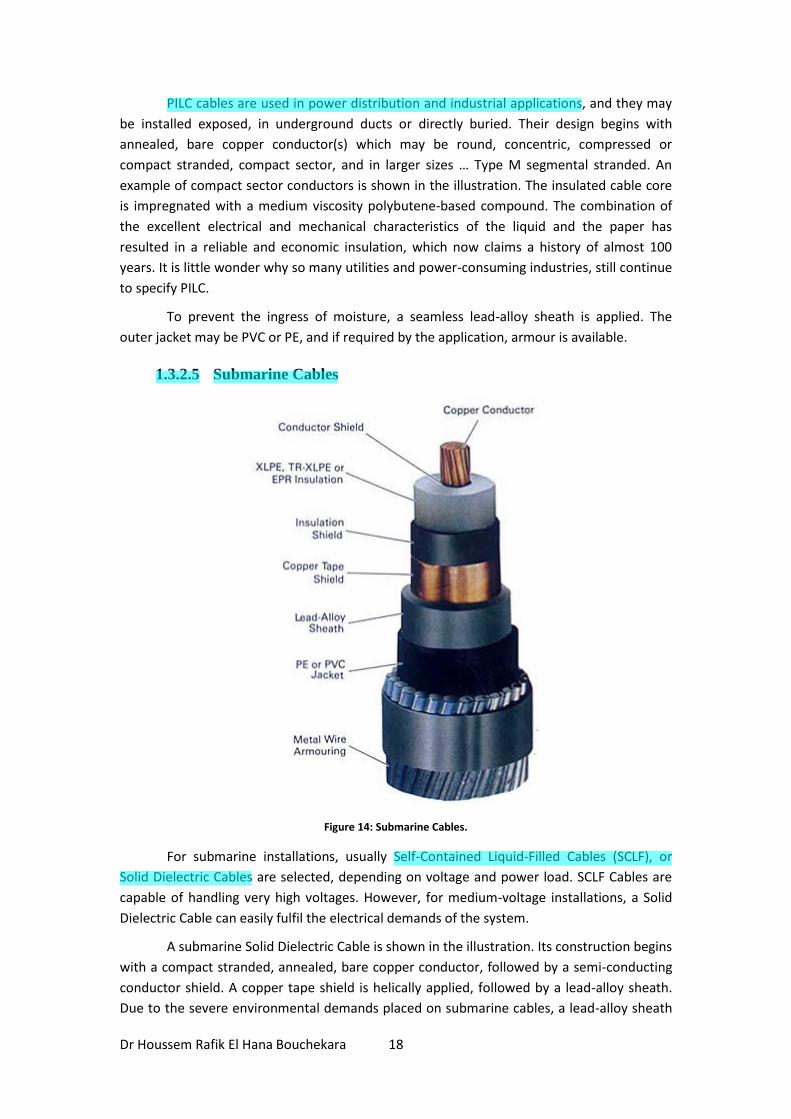
1.3.2.5 Submarine Cables
Figure 14: Submarine Cables.
For submarine installations, usually Self-Contained Liquid-Filled Cables (SCLF), or
Solid Dielectric Cables are selected, depending on voltage and power load. SCLF Cables are
capable of handling very high voltages. However, for medium-voltage installations, a Solid
Dielectric Cable can easily fulfil the electrical demands of the system.
A submarine Solid Dielectric Cable is shown in the illustration. Its construction begins
with a compact stranded, annealed, bare copper conductor, followed by a semi-conducting
conductor shield. A copper tape shield is helically applied, followed by a lead-alloy sheath.
Due to the severe environmental demands placed on submarine cables, a lead-alloy sheath
Davut
Highlight
Davut
Highlight
Davut
Highlight
Dr Houssem Rafik El Hana Bouchekara 19
is often specified because of its compressibility, flexibility and resistance to moisture and
corrosion. The sheath is usually covered by a number of outer layers, comprising a PE or PVC
jacket and metal wire armouring.
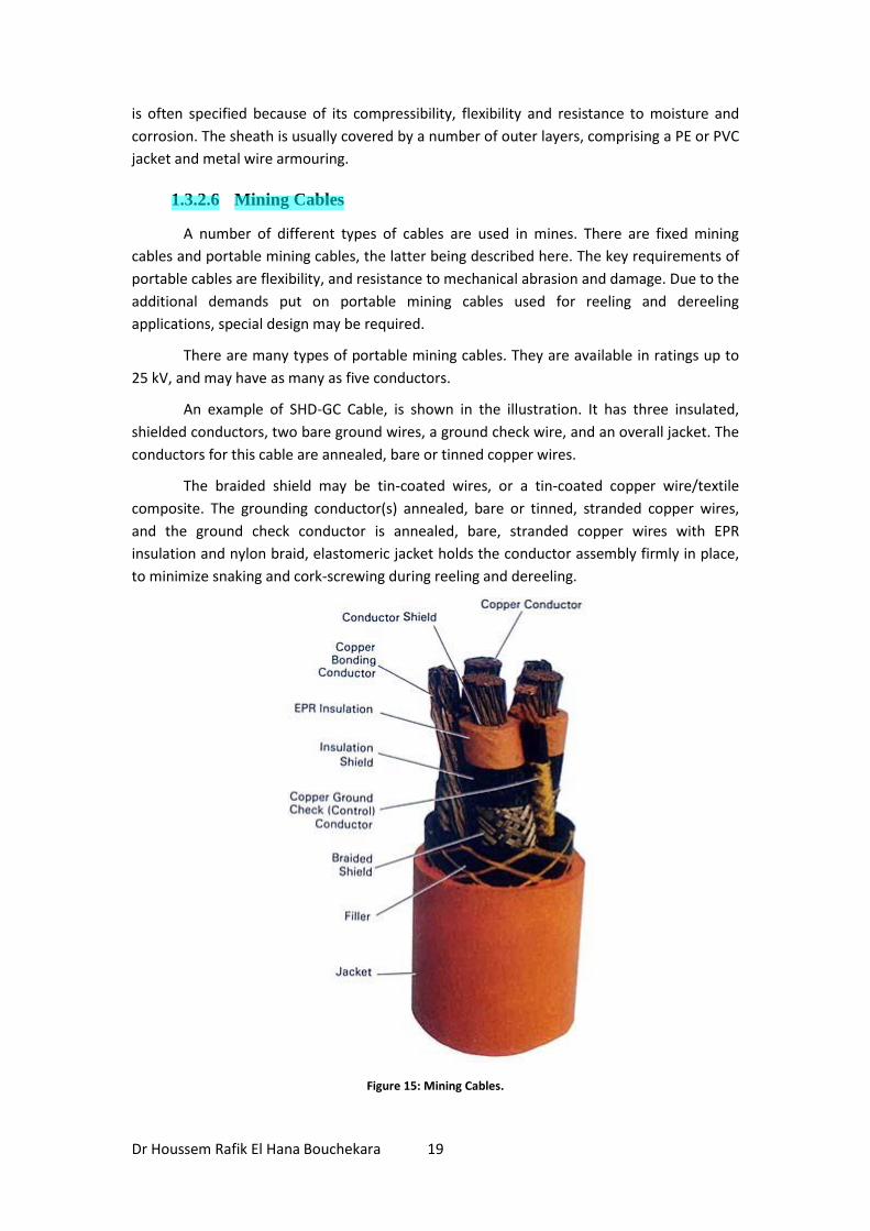
1.3.2.6 Mining Cables
A number of different types of cables are used in mines. There are fixed mining
cables and portable mining cables, the latter being described here. The key requirements of
portable cables are flexibility, and resistance to mechanical abrasion and damage. Due to the
additional demands put on portable mining cables used for reeling and dereeling
applications, special design may be required.
There are many types of portable mining cables. They are available in ratings up to
25 kV, and may have as many as five conductors.
An example of SHD-GC Cable, is shown in the illustration. It has three insulated,
shielded conductors, two bare ground wires, a ground check wire, and an overall jacket. The
conductors for this cable are annealed, bare or tinned copper wires.
The braided shield may be tin-coated wires, or a tin-coated copper wire/textile
composite. The grounding conductor(s) annealed, bare or tinned, stranded copper wires,
and the ground check conductor is annealed, bare, stranded copper wires with EPR
insulation and nylon braid, elastomeric jacket holds the conductor assembly firmly in place,
to minimize snaking and cork-screwing during reeling and dereeling.
Figure 15: Mining Cables.
Davut
Highlight
Dr Houssem Rafik El Hana Bouchekara 20
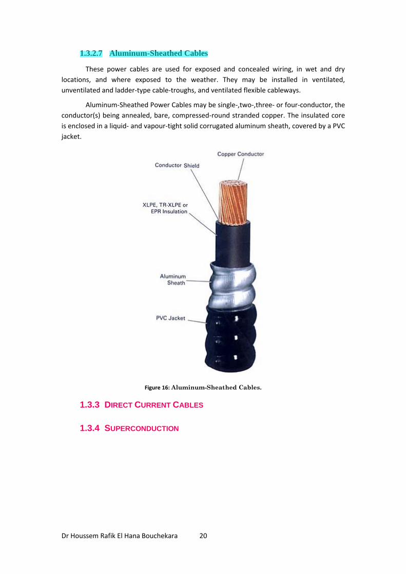
1.3.2.7 Aluminum-Sheathed Cables
These power cables are used for exposed and concealed wiring, in wet and dry
locations, and where exposed to the weather. They may be installed in ventilated,
unventilated and ladder-type cable-troughs, and ventilated flexible cableways.
Aluminum-Sheathed Power Cables may be single-,two-,three- or four-conductor, the
conductor(s) being annealed, bare, compressed-round stranded copper. The insulated core
is enclosed in a liquid- and vapour-tight solid corrugated aluminum sheath, covered by a PVC
jacket.
Figure 16: Aluminum-Sheathed Cables.
1.3.3 DIRECT CURRENT CABLES
1.3.4 SUPERCONDUCTION
Davut
Highlight
Dr Houssem Rafik El Hana Bouchekara 21
1.4 ELECTRICAL CHARACTERISTICS OF INSULATED CABLES
1.4.1 ELECTRIC STRESS IN SINGLE CONDUCTOR CABLE
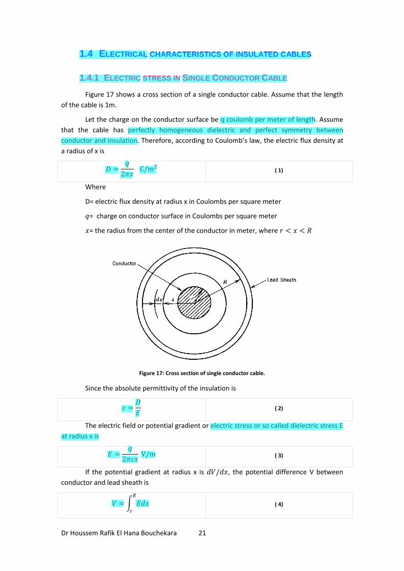
Figure 17 shows a cross section of a single conductor cable. Assume that the length
of the cable is 1m.
Let the charge on the conductor surface be q coulomb per meter of length. Assume
that the cable has perfectly homogeneous dielectric and perfect symmetry between
conductor and insulation. Therefore, according to Coulomb’s law, the electric flux density at
a radius of x is
𝐷 =𝑞
2𝜋𝑥 C/m2 ( 1)
Where
D= electric flux density at radius x in Coulombs per square meter
𝑞= charge on conductor surface in Coulombs per square meter
𝑥= the radius from the center of the conductor in meter, where 𝑟 < 𝑥 < 𝑅
Figure 17: Cross section of single conductor cable.
Since the absolute permittivity of the insulation is
휀 =𝐷
𝐸 ( 2)
The electric field or potential gradient or electric stress or so called dielectric stress E
at radius x is
𝐸 =𝑞
2𝜋휀𝑥 V/m ( 3)
If the potential gradient at radius x is 𝑑𝑉/𝑑𝑥, the potential difference V between
conductor and lead sheath is
𝑉 = 𝐸𝑑𝑥𝑅
𝑟
( 4)
Davut
Highlight
Davut
Highlight
Davut
Highlight
Davut
Highlight
Davut
Highlight
Davut
Highlight
Davut
Highlight
Davut
Highlight
Davut
Highlight
Dr Houssem Rafik El Hana Bouchekara 22
Or
𝑉 = 𝑞
2𝜋휀𝑥 𝑑𝑥
𝑅
𝑟
( 5)
So
𝑉 =𝑞
2𝜋휀ln
𝑅
𝑟 V ( 6)
Therefore,
𝐸 =𝑉
𝑥 ln𝑅𝑟
V/m ( 7)
Where
E= electric stress of cable in volts per meter
V= potential difference between conductor and lead sheath in volts
𝑥= distance from center of conductor in meter
R= outside radius of insulation or inside radius of lead sheath in meters
𝑟= radius of conductor in meter
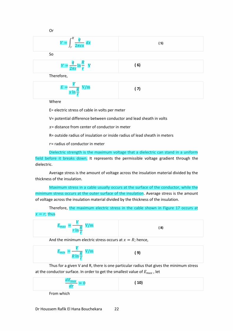
Dielectric strength is the maximum voltage that a dielectric can stand in a uniform
field before it breaks down. It represents the permissible voltage gradient through the
dielectric.
Average stress is the amount of voltage across the insulation material divided by the
thickness of the insulation.
Maximum stress in a cable usually occurs at the surface of the conductor, while the
minimum stress occurs at the outer surface of the insulation. Average stress is the amount
of voltage across the insulation material divided by the thickness of the insulation.
Therefore, the maximum electric stress in the cable shown in Figure 17 occurs at
𝑥 = 𝑟; thus
𝐸𝑚𝑎𝑥 =𝑉
𝑟 ln𝑅𝑟
V/m ( 8)
And the minimum electric stress occurs at 𝑥 = 𝑅; hence,
𝐸𝑚𝑖𝑛 =𝑉
𝑅 ln𝑅𝑟
V/m ( 9)
Thus for a given V and R, there is one particular radius that gives the minimum stress
at the conductor surface. In order to get the smallest value of 𝐸𝑚𝑎𝑥 , let
𝑑𝐸𝑚𝑎𝑥
𝑑𝑟= 0 ( 10)
From which
Davut
Highlight
Davut
Highlight
Davut
Highlight
Davut
Highlight
Davut
Highlight
Davut
Highlight
Davut
Highlight
Davut
Highlight
Davut
Highlight
Dr Houssem Rafik El Hana Bouchekara 23
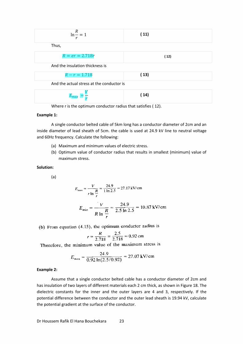
ln𝑅
𝑟= 1 ( 11)
Thus,
𝑅 = 𝑒𝑟 = 2.718𝑟 ( 12)
And the insulation thickness is
𝑅 − 𝑟 = 1.718 ( 13)
And the actual stress at the conductor is
𝐸𝑚𝑎𝑥 =𝑉
𝑟 ( 14)
Where r is the optimum conductor radius that satisfies ( 12).
Example 1:
A single conductor belted cable of 5km long has a conductor diameter of 2cm and an
inside diameter of lead sheath of 5cm. the cable is used at 24.9 kV line to neutral voltage
and 60Hz frequency. Calculate the following:
(a) Maximum and minimum values of electric stress.
(b) Optimum value of conductor radius that results in smallest (minimum) value of
maximum stress.
Solution:
(a)
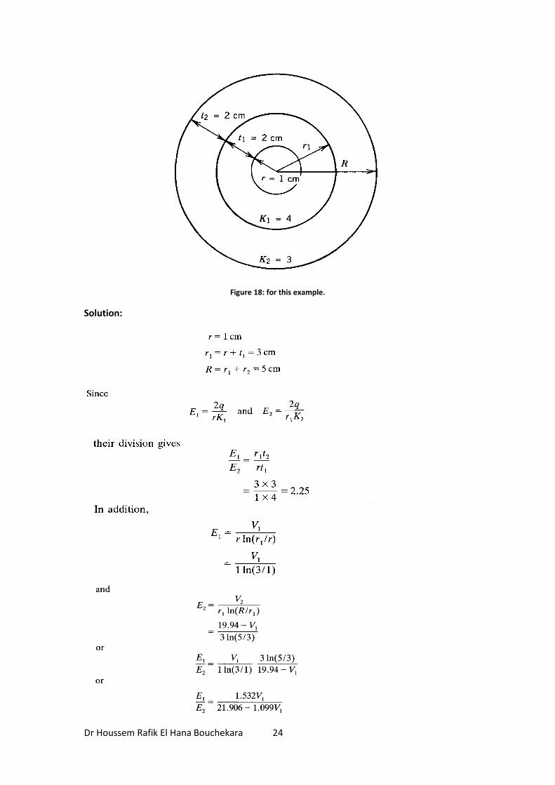
Example 2:
Assume that a single conductor belted cable has a conductor diameter of 2cm and
has insulation of two layers of different materials each 2 cm thick, as shown in Figure 18. The
dielectric constants for the inner and the outer layers are 4 and 3, respectively. If the
potential difference between the conductor and the outer lead sheath is 19.94 kV, calculate
the potential gradient at the surface of the conductor.
Davut
Highlight
Davut
Highlight
Davut
Highlight
Dr Houssem Rafik El Hana Bouchekara 24
Figure 18: for this example.
Solution:
Dr Houssem Rafik El Hana Bouchekara 25
1.4.2 CAPACITANCE OF SINGLE CONDUCTOR CABLE
Assume that the potential difference is V between the conductor and the lead
sheath of single conductor cable shown in Figure 17. Let the charge on the conductor and
sheath be +q and –q C/m of length. From the equation of the voltage given by
𝑉 =𝑞
2𝜋휀ln
𝑅
𝑟 V ( 15)
Where
V= potential difference between conductor and lead sheath in volts
휀= absolute permittivity of insulation
R= outside radius of insulation in meters
𝑟= radius of conductor in meter
Therefore, the capacitance between the conductor and the sheath is
𝐶 =𝑞
𝑉 ( 16)
Or
𝐶 =2𝜋휀
ln 𝑅𝑟
F/m ( 17)
Since
휀 = 휀0𝐾 ( 18)
Therefore
𝐶 =2𝜋휀0𝐾
ln 𝑅𝑟
F/m ( 19)
Davut
Highlight
Davut
Highlight
Davut
Highlight
Davut
Highlight
Davut
Highlight
Davut
Highlight
Davut
Highlight
Dr Houssem Rafik El Hana Bouchekara 26
Where
휀0 =1
36𝜋 × 109 for air
= 8.85 × 10⁻¹² F/m ( 20)
And
K= dielectric constant of cable insulation
Therefore,
𝐶 =10−9𝐾
18 ln 𝑅𝑟
F/m ( 21)
Or
𝐶 =𝐾
18 ln 𝑅𝑟
𝜇F/km ( 22)
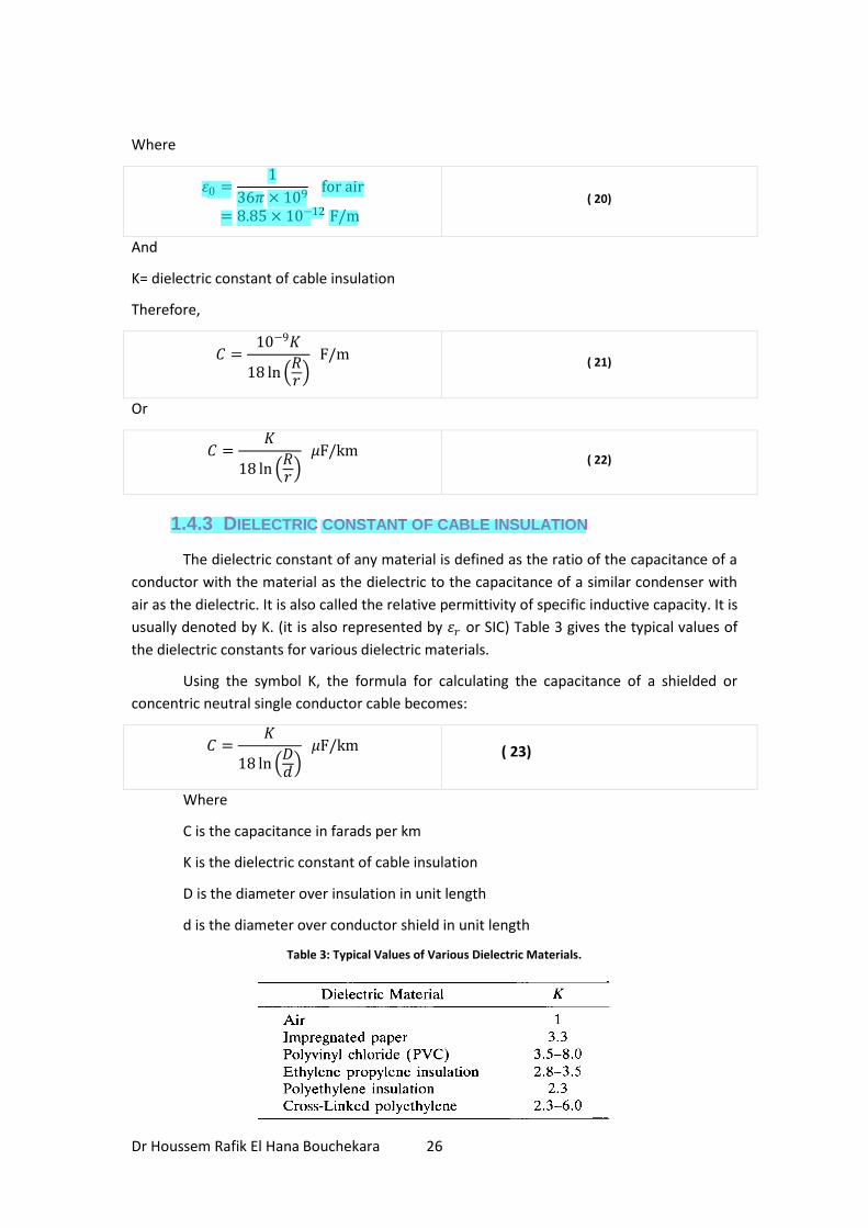
1.4.3 DIELECTRIC CONSTANT OF CABLE INSULATION
The dielectric constant of any material is defined as the ratio of the capacitance of a
conductor with the material as the dielectric to the capacitance of a similar condenser with
air as the dielectric. It is also called the relative permittivity of specific inductive capacity. It is
usually denoted by K. (it is also represented by 휀𝑟 or SIC) Table 3 gives the typical values of
the dielectric constants for various dielectric materials.
Using the symbol K, the formula for calculating the capacitance of a shielded or
concentric neutral single conductor cable becomes:
𝐶 =𝐾
18 ln 𝐷𝑑
𝜇F/km ( 23)
Where
C is the capacitance in farads per km
K is the dielectric constant of cable insulation
D is the diameter over insulation in unit length
d is the diameter over conductor shield in unit length
Table 3: Typical Values of Various Dielectric Materials.
Davut
Highlight
Davut
Highlight
Dr Houssem Rafik El Hana Bouchekara 27
1.4.4 CHARGING CURRENT
By definition of susceptance,
𝐵 = 𝜔𝐶 S ( 24)
Or
𝐵 = 2𝜋𝑓𝐶 S ( 25)
Then the admittance Y corresponding to C is
𝑌 = 𝑗𝐵 ( 26)
Or
𝑌 = 𝑗2𝜋𝑓𝐶 S ( 27)
Therefore, the charging current is
𝐼𝐶 = 𝑌𝑉𝐿−𝑁 ( 28)
Or
𝐼𝐶 = 2𝜋𝑓𝐶𝑉𝐿−𝑁 ( 29)
So we can write
𝐼𝐶 =2𝜋𝑓 𝐾 𝑉𝐿−𝑁
18 ln 𝐷𝑑
10−9 A ( 30)
Where,
𝑓 is the frequency in hertz
D is the diameter over insulation in unit length
𝑑 is the diameter over conductor shield in unit length
K is the dielectric constant of cable insulation
V line to neutral voltage
The charging current and the capacitance are relatively greater for insulated cables
than in overhead circuits because of closer spacing and the higher dielectric constant of the
insulation of the cable. In general, the charging current is negligible for overhead circuits at
distribution voltages, contrary to high voltage transmission circuits.
1.4.5 DETERMINATION OF INSULATION RESISTANCE OF SINGLE
CONDUCTOR CABLE
Assume that the cable shown in Figure 19 has a length of 1m.
Davut
Highlight
Davut
Highlight
Davut
Highlight
Davut
Highlight
Davut
Highlight
Davut
Highlight
Dr Houssem Rafik El Hana Bouchekara 28
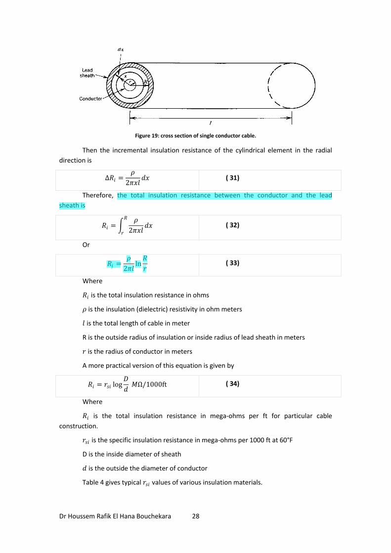
Figure 19: cross section of single conductor cable.
Then the incremental insulation resistance of the cylindrical element in the radial
direction is
∆𝑅𝑖 =𝜌
2𝜋𝑥𝑙𝑑𝑥 ( 31)
Therefore, the total insulation resistance between the conductor and the lead
sheath is
𝑅𝑖 = 𝜌
2𝜋𝑥𝑙𝑑𝑥
𝑅
𝑟
( 32)
Or
𝑅𝑖 =𝜌
2𝜋𝑙ln
𝑅
𝑟 ( 33)
Where
𝑅𝑖 is the total insulation resistance in ohms
𝜌 is the insulation (dielectric) resistivity in ohm meters
𝑙 is the total length of cable in meter
R is the outside radius of insulation or inside radius of lead sheath in meters
𝑟 is the radius of conductor in meters
A more practical version of this equation is given by
𝑅𝑖 = 𝑟𝑠𝑖 log𝐷
𝑑 𝑀Ω/1000ft ( 34)
Where
𝑅𝑖 is the total insulation resistance in mega-ohms per ft for particular cable
construction.
𝑟𝑠𝑖 is the specific insulation resistance in mega-ohms per 1000 ft at 60°F
D is the inside diameter of sheath
𝑑 is the outside the diameter of conductor
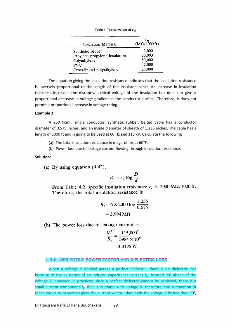
Table 4 gives typical 𝑟𝑠𝑖 values of various insulation materials.
Davut
Highlight
Davut
Highlight
Dr Houssem Rafik El Hana Bouchekara 29
Table 4: Typical values of 𝒓𝒔𝒊
The equation giving the insulation resistance indicates that the insulation resistance
is inversely proportional to the length of the insulated cable. An increase in insulation
thickness increases the disruptive critical voltage of the insulation but does not give a
proportional decrease in voltage gradient at the conductor surface. Therefore, it does not
permit a proportional increase in voltage rating.
Example 3:
A 250 kcmil, single conductor, synthetic rubber, belted cable has a conductor
diameter of 0.575 inches, and an inside diameter of sheath of 1.235 inches. The cable has a
length of 6000 ft and is going to be used at 60 Hz and 115 kV. Calculate the following
(a) The total insulation resistance in mega-ohms at 60°F.
(b) Power loss due to leakage current flowing through insulation resistance.
Solution:
1.4.6 DIELECTRIC POWER FACTOR AND DIELECTRIC LOSS
When a voltage is applied across a perfect dielectric, there is no dielectric loss
because of the existence of an induced capacitance current 𝐼𝐶 , located 90° ahead of the
voltage V. however, in practices, since a perfect dielectric cannot be achieved, there is a
small current component 𝐼𝑉 that is in phase with voltage V. therefore, the summation of
these two current vectors gives the current vector I that leads the voltage V by less than 90°,
Davut
Highlight
Davut
Highlight
Dr Houssem Rafik El Hana Bouchekara 30
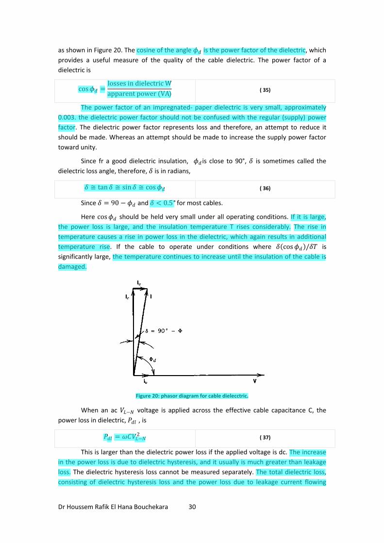
as shown in Figure 20. The cosine of the angle 𝜙𝑑 is the power factor of the dielectric, which
provides a useful measure of the quality of the cable dielectric. The power factor of a
dielectric is
cos𝜙𝑑 =losses in dielectric W
apparent power (VA) ( 35)
The power factor of an impregnated- paper dielectric is very small, approximately
0.003. the dielectric power factor should not be confused with the regular (supply) power
factor. The dielectric power factor represents loss and therefore, an attempt to reduce it
should be made. Whereas an attempt should be made to increase the supply power factor
toward unity.
Since fr a good dielectric insulation, 𝜙𝑑 is close to 90°, 𝛿 is sometimes called the
dielectric loss angle, therefore, 𝛿 is in radians,
𝛿 ≅ tan𝛿 ≅ sin𝛿 ≅ cos𝜙𝑑 ( 36)
Since 𝛿 = 90 − 𝜙𝑑 and 𝛿 < 0.5° for most cables.
Here cos𝜙𝑑 should be held very small under all operating conditions. If it is large,
the power loss is large, and the insulation temperature T rises considerably. The rise in
temperature causes a rise in power loss in the dielectric, which again results in additional
temperature rise. If the cable to operate under conditions where 𝛿 cos𝜙𝑑 /𝛿𝑇 is
significantly large, the temperature continues to increase until the insulation of the cable is
damaged.
Figure 20: phasor diagram for cable dielecctric.
When an ac 𝑉𝐿−𝑁 voltage is applied across the effective cable capacitance C, the
power loss in dielectric, 𝑃𝑑𝑙 , is
𝑃𝑑𝑙 = 𝜔𝐶𝑉𝐿−𝑁2 ( 37)
This is larger than the dielectric power loss if the applied voltage is dc. The increase
in the power loss is due to dielectric hysteresis, and it usually is much greater than leakage
loss. The dielectric hysteresis loss cannot be measured separately. The total dielectric loss,
consisting of dielectric hysteresis loss and the power loss due to leakage current flowing
Davut
Highlight
Davut
Highlight
Davut
Highlight
Davut
Highlight
Davut
Highlight
Davut
Highlight
Davut
Highlight
Davut
Highlight
Davut
Highlight
Davut
Highlight
Davut
Highlight
Davut
Highlight
Davut
Highlight
Dr Houssem Rafik El Hana Bouchekara 31
through the insulation resistance can be measured by means of the Schering bridge. These
losses depend on voltage, frequency, and the stat of the cable dielectric. Therefore, the test
has to be made at rated voltage and frequency for a given cable.
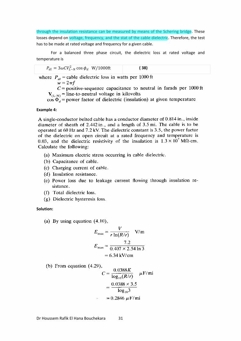
For a balanced three phase circuit, the dielectric loss at rated voltage and
temperature is
𝑃𝑑𝑙 = 3𝜔𝐶𝑉𝐿−𝑁2 cos𝜙𝑑 W/1000ft ( 38)
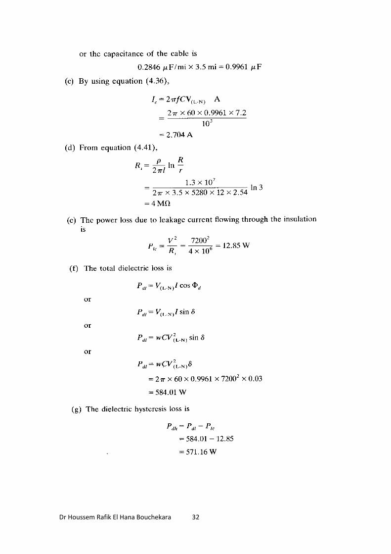
Example 4:
Solution:
Davut
Highlight
Davut
Highlight
Dr Houssem Rafik El Hana Bouchekara 32
Dr Houssem Rafik El Hana Bouchekara 33
1.5 LOCATION OF FAULTS IN UNDERGROUND CABLES
Davut
Highlight