Transistors - Neff Site · Transistors •Structure –Bipolar junction transistor (BJT) –Two p-n...
12
Transistors Networks and Embedded Software Module 3.1.2 by Wolfgang Neff
-
Upload
nguyenxuyen -
Category
Documents
-
view
237 -
download
0
Transcript of Transistors - Neff Site · Transistors •Structure –Bipolar junction transistor (BJT) –Two p-n...
Transistors
Networks and Embedded Software
Module 3.1.2
by Wolfgang Neff

Transistors
• Structure
– Bipolar junction transistor (BJT)
– Two p-n junctions
• NPN transistor
• PNP transistor
– Third connection
• Insulator
• Conductor
2016-11-19 Module 3.1.2 – Transistors 2
N-type
P-type
P-type
P-type
N-type
N-type
Depletion region
N-type
N-type
P-type P-type
N-type
N-type

• Characteristics
– Collector current flows if base current flows
– Base current flows into base
– Positive voltage drop between base and emitter necessary
NPN Transistors (1)
2016-11-19 Module 3.1.2 – Transistors 3
Collector
Emitter
Base
IC
IE
IB
UBE

• Application: switch
– Load in collector branch
– Controlled by base
– Switch is
• On if UBE is positive
• Off if UBE is zero
– Active high
• On if UBE is high
• Off if UBE is low
NPN Transistors (2)
2016-11-19 Module 3.1.2 – Transistors 4
Low voltage
C
B
E
High voltage
Load
UBE
on
offUBE = low
UBE = high
IC

NPN Transistors (3)
• Example: BC547
– Maximum collector current
• IC = 100 mA
– Base saturation voltage
• UBE = 0.7 V
– DC current gain
• ℎ𝐹𝐸 =𝐼𝑐
𝐼𝐵
• hFE ≈ 250
2016-11-19 Module 3.1.2 – Transistors 5
1 2 3
1 Collector2 Base3 Emitter
1
3
2

PNP Transistors (1)
• Characteristics
– Collector current flows if base current flows
– Base current flows out of base
– Negative voltage drop between base and emitter necessary
2016-11-19 Module 3.1.2 – Transistors 6
Collector
Emitter
Base
IC
IE
IB
UBE

• Application: switch
– Load in collector branch
– Controlled by base
– Switch is
• On if UBE is negative
• Off if UBE is zero
– Active low
• On if UBE is low
• Off if UBE is high
PNP Transistors (2)
2016-11-19 Module 3.1.2 – Transistors 7
UBE
Low voltage
High voltage
C
B
E
Load
on
off
UBE = low
UBE = high
IC

PNP Transistors (3)
• Example: BC557
– Maximum collector current
• IC = -100 mA
– Base saturation voltage
• UBE = -0.7 V
– DC current gain
• ℎ𝐹𝐸 =𝐼𝑐
𝐼𝐵
• hFE ≈ 250
2016-11-19 Module 3.1.2 – Transistors 8
1 2 3
1 Collector2 Base3 Emitter
1
3
2

• Metal-Oxide-Semiconductor
– Composition
• Field-Effect Transistor
– Operating mode
– Controlled by voltage
• No current necessary
• Energy efficient
MOSFET (1)
2016-11-19 Module 3.1.2 – Transistors 9
Gate
Drain
Source
N-channel, enhancement mode
Gate
Drain
Source
P-channel, enhancement mode

MOSFET (2)
• Application: switch
– N-Channel• Drain current
– On if gate high
– Off if gate low
• Active high
– P-Channel• Drain current
– On if gate low
– Off if gate high
• Active low
2016-11-19 Module 3.1.2 – Transistors 10
L
off
H
on
L
on
H
off
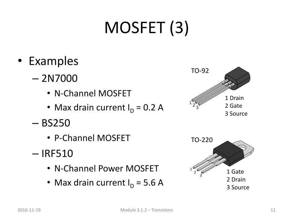
MOSFET (3)
• Examples
– 2N7000
• N-Channel MOSFET
• Max drain current ID = 0.2 A
– BS250
• P-Channel MOSFET
– IRF510
• N-Channel Power MOSFET
• Max drain current ID = 5.6 A
2016-11-19 Module 3.1.2 – Transistors 11
1 Drain2 Gate3 Source
TO-92
12
31 Gate2 Drain3 Source
TO-220

MOSFET (4)
• Comparison
– NPN / N-Channel – PNP / P-Channel
2016-11-19 Module 3.1.2 – Transistors 12
Basis
Collector
Emitter
Basis
Collector
Emitter
BJT
Gate
Drain
Source
Gate
Drain
Source
MOSFET