Transistor Clock Assembly Manualtransistorclock.com/tranmanual.pdfTo all the experienced electronic...
61
Transistor Clock Assembly Manual
Transcript of Transistor Clock Assembly Manualtransistorclock.com/tranmanual.pdfTo all the experienced electronic...
Transistor Clock Assembly Manual

K A B T R O N I C S
Transistor Wall Clock Kit Page 2
Table of Contents
INTRODUCTION .................................................................................................. 3
UNPACKING/PARTS LIST .................................................................................. 4
SOLDERING ........................................................................................................ 5
ASSEMBLY INSTRUCTIONS .............................................................................. 7
PARTS IDENTIFICATION .................................................................................. 22
THEORY OF OPERATION ................................................................................. 25
CIRCUIT DESCRIPTION .................................................................................... 31
IN CASE OF DIFFICULTY ................................................................................. 38
SPECIFICATIONS .............................................................................................. 43
CIRCUIT BOARD VIEWS ................................................................................... 44
SCHEMATIC ...................................................................................................... 46
REMOVABLE COMPONENT IDENTIFIER PAGE ............................................. 61
Copyright © Feb 3, 2011 by KABtronics Document version 1.4 for use with PC board version 4
K A B T R O N I C S I N T R O D U C T I O N
Transistor Wall Clock Kit Page 3
Introduction Thanks for buying this kit. After 10-15 hours of assembly, and with a clock to show for your efforts, I hope you will thank me for offering this kit.
To all the experienced electronic hobbyists, let me apologize right now for the simple tone and overload of information in this manual, I am attempting to give enough information to allow a motivated beginner a chance to get this working. All you experienced folks can turn right now to the assembly section and go for it (watch out for the 7-segment LED placement, otherwise, this kit really is as simple as it seems). I do suggest you build the sections in the order listed and do the tests as you build.
If you are not skilled in soldering parts onto a PC board, you should read the soldering section and also search the web to learn about soldering, there are many good sites that teach soldering.
You need to make 2700+ good solder joints to have the clock work.
If you are not familiar with components, you should read the parts identification section, but frankly, this kit was designed for a somewhat knowledgeable electronic hobbyist. Be certain of a part before you solder it.
If you are not familiar with basic electronic circuits, you are embarking on a great gamble. One could conceivable solder all the parts onto the board and get a working clock, but frankly, even I, the designer of the clock, have soldered an occasional diode backwards, or misplaced an NPN transistor for a PNP. It is basic circuit troubleshooting that will allow you to find the error and correct it. I attempt to guide you when/if you are chasing a problem, but you will need to think hard about what you are seeing and what type of error would cause it.

K A B T R O N I C S U N P A C K I N G / P A R T S L I S T
Transistor Wall Clock Kit Page 4
Unpacking/Parts List Gently unpack the contents of the box, being especially careful not to open any bags of parts at this time. You will open these bags as the parts are needed. Check off the items below as you unpack. This will also serve as a chance to become familiar with the parts.
Check Item Note X Assembly Manual This document Printed Circuit Board Under cardboard Solder 2 sticks Unsolder braid 1 roll Nylon tie strap Wall Transformer In small Box Switches 2 position Wire Terminal 6,800 uF electrolytic Capacitor 220 pico Farad capacitors 0.001 micro Farad Capacitor 0.01 micro Farad Capacitor 0.1 micro Farad Capacitor Large Diodes Small Diodes 680 Ohm Resistors 1K Ohm Resistors 10K Ohm Resistors 100K Ohm Resistors 1M Ohm Resistors NPN Transistors (2N3904) PNP Transistors (2N3906) 7 segment LED displays LSD8161-11 Single LEDs Mounting Kit Screws, spacers
K A B T R O N I C S S O L D E R I N G
Transistor Wall Clock Kit Page 5
Soldering
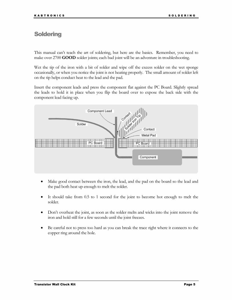
This manual can’t teach the art of soldering, but here are the basics. Remember, you need to make over 2700 GOOD solder joints; each bad joint will be an adventure in troubleshooting.
Wet the tip of the iron with a bit of solder and wipe off the excess solder on the wet sponge occasionally, or when you notice the joint is not heating properly. The small amount of solder left on the tip helps conduct heat to the lead and the pad.
Insert the component leads and press the component flat against the PC Board. Slightly spread the leads to hold it in place when you flip the board over to expose the back side with the component lead facing up.
• Make good contact between the iron, the lead, and the pad on the board so the lead and the pad both heat up enough to melt the solder.
• It should take from 0.5 to 1 second for the joint to become hot enough to melt the solder.
• Don’t overheat the joint, as soon as the solder melts and wicks into the joint remove the iron and hold still for a few seconds until the joint freezes.
• Be careful not to press too hard as you can break the trace right where it connects to the copper ring around the hole.
K A B T R O N I C S S O L D E R I N G
Transistor Wall Clock Kit Page 6
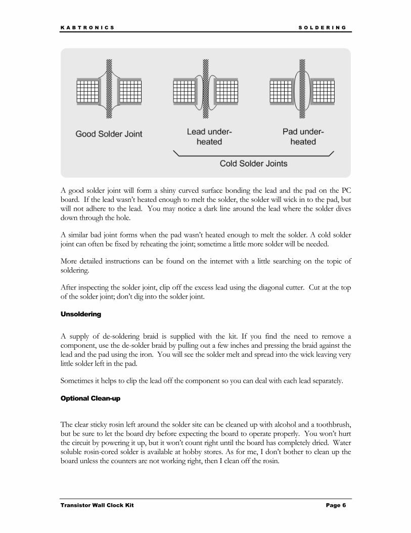
A good solder joint will form a shiny curved surface bonding the lead and the pad on the PC board. If the lead wasn’t heated enough to melt the solder, the solder will wick in to the pad, but will not adhere to the lead. You may notice a dark line around the lead where the solder dives down through the hole.
A similar bad joint forms when the pad wasn’t heated enough to melt the solder. A cold solder joint can often be fixed by reheating the joint; sometime a little more solder will be needed.
More detailed instructions can be found on the internet with a little searching on the topic of soldering.
After inspecting the solder joint, clip off the excess lead using the diagonal cutter. Cut at the top of the solder joint; don’t dig into the solder joint.
Unsoldering
A supply of de-soldering braid is supplied with the kit. If you find the need to remove a component, use the de-solder braid by pulling out a few inches and pressing the braid against the lead and the pad using the iron. You will see the solder melt and spread into the wick leaving very little solder left in the pad.
Sometimes it helps to clip the lead off the component so you can deal with each lead separately.
Optional Clean-up
The clear sticky rosin left around the solder site can be cleaned up with alcohol and a toothbrush, but be sure to let the board dry before expecting the board to operate properly. You won’t hurt the circuit by powering it up, but it won’t count right until the board has completely dried. Water soluble rosin-cored solder is available at hobby stores. As for me, I don’t bother to clean up the board unless the counters are not working right, then I clean off the rosin.
K A B T R O N I C S A S S E M B L Y I N S T R U C T I O N S
Transistor Wall Clock Kit Page 7
Assembly Instructions At the risk of being called a smarty pants, the assembly instructions are;
Place each component in its identified location with its leads through the proper holes, solder the leads into place leaving the component snugly against the PC board, and clip the component leads flush with the top of the solder joint. Repeat for all 1256 components. OK, that’s a bit too short. After the following general information, there are detailed instructions.
Find a location to build this clock where you have room to place the board and still have room to place the components within easy reach. With over 1250 parts to reach, you want to make the reaching easy. Place a garbage can within reach of the work, you will find you need to deal with over 2700 clipped off leads of components, these can become quite a nuisance if they start to pile up.
You will need the following tools to build your clock.
• Soldering Iron meant for electrical work • Small Diagonal Cutter • Very small flat-blade screwdriver to tighten the wire terminals • A VOM meter to check for shorts and power supply operation • Maybe an oscilloscope, while not necessary, may come in useful if you find yourself
unable to diagnose a problem. If you can’t fix your problem by inspection and location of bad soldering or misplaced components, you will need an oscilloscope.
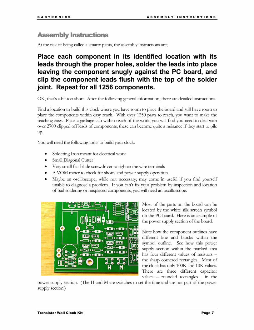
Most of the parts on the board can be located by the white silk screen symbol on the PC board. Here is an example of the power supply section of the board.
Note how the component outlines have different line and blocks within the symbol outline. See how this power supply section within the marked area has four different values of resistors – the sharp cornered rectangles. Most of the clock has only 100K and 10K values. There are three different capacitor values – rounded rectangles - in the
power supply section. (The H and M are switches to set the time and are not part of the power supply section.)
K A B T R O N I C S A S S E M B L Y I N S T R U C T I O N S
Transistor Wall Clock Kit Page 8
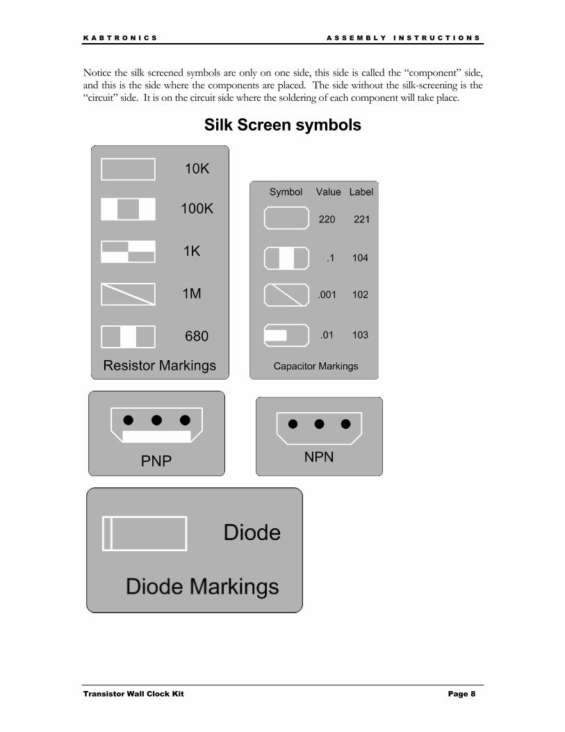
Notice the silk screened symbols are only on one side, this side is called the “component” side, and this is the side where the components are placed. The side without the silk-screening is the “circuit” side. It is on the circuit side where the soldering of each component will take place.
Silk Screen symbols
K A B T R O N I C S A S S E M B L Y I N S T R U C T I O N S
Transistor Wall Clock Kit Page 9
Assemble Power Supply Here are step-by-step assemble instructions for the power supply section. The other sections will not be as detailed.
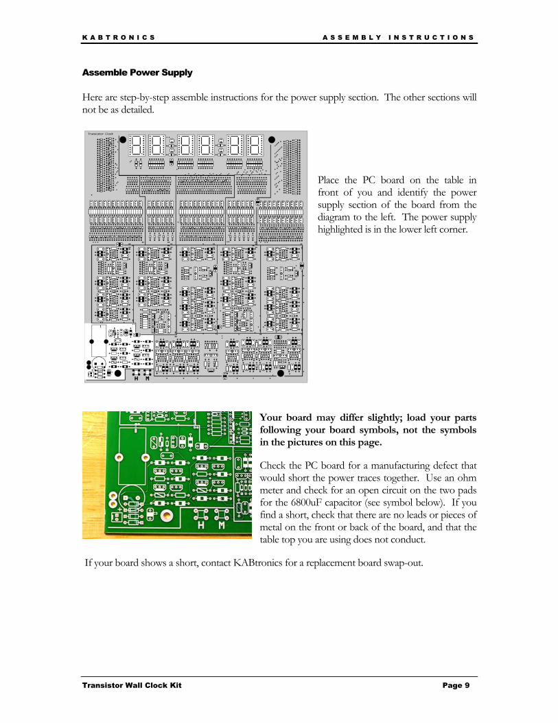
Place the PC board on the table in front of you and identify the power supply section of the board from the diagram to the left. The power supply highlighted is in the lower left corner.
Your board may differ slightly; load your parts following your board symbols, not the symbols in the pictures on this page.
Check the PC board for a manufacturing defect that would short the power traces together. Use an ohm meter and check for an open circuit on the two pads for the 6800uF capacitor (see symbol below). If you find a short, check that there are no leads or pieces of metal on the front or back of the board, and that the table top you are using does not conduct.
If your board shows a short, contact KABtronics for a replacement board swap-out.

K A B T R O N I C S A S S E M B L Y I N S T R U C T I O N S
Transistor Wall Clock Kit Page 10
Here is a table of the parts you will load in the power supply section. This table only shows the parts in the power supply section
Find these parts in the kit and prepare to load them.
QTY Item Symbol Note 11 100K resistor
4 10K resistor
2 1 Meg resistor Unique to Power Supply
1 1K resistor Unique to Power Supply
4 large diode Unique to Power Supply
1 small diode
4 PNP transistor
5 NPN transistor
3 0.1 capacitor
1 0.001 capacitor
Unique to Power Supply
1 0.01 capacitor
Unique to Power Supply
1 6800 uF capacitor Unique to Power Supply
1 terminal connector Unique to Power Supply
K A B T R O N I C S A S S E M B L Y I N S T R U C T I O N S
Transistor Wall Clock Kit Page 11
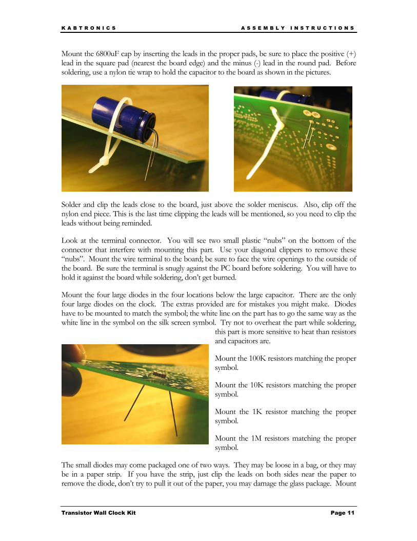
Mount the 6800uF cap by inserting the leads in the proper pads, be sure to place the positive (+) lead in the square pad (nearest the board edge) and the minus (-) lead in the round pad. Before soldering, use a nylon tie wrap to hold the capacitor to the board as shown in the pictures.
Solder and clip the leads close to the board, just above the solder meniscus. Also, clip off the nylon end piece. This is the last time clipping the leads will be mentioned, so you need to clip the leads without being reminded.
Look at the terminal connector. You will see two small plastic “nubs” on the bottom of the connector that interfere with mounting this part. Use your diagonal clippers to remove these “nubs”. Mount the wire terminal to the board; be sure to face the wire openings to the outside of the board. Be sure the terminal is snugly against the PC board before soldering. You will have to hold it against the board while soldering, don’t get burned.
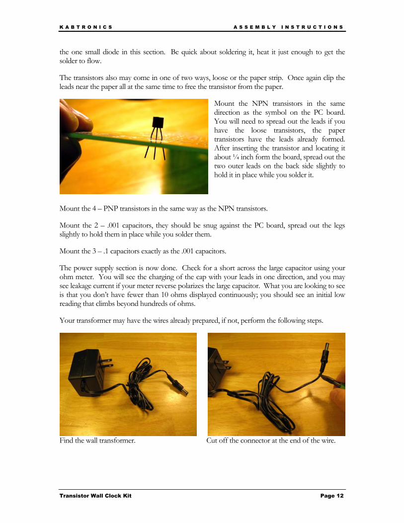
Mount the four large diodes in the four locations below the large capacitor. There are the only four large diodes on the clock. The extras provided are for mistakes you might make. Diodes have to be mounted to match the symbol; the white line on the part has to go the same way as the white line in the symbol on the silk screen symbol. Try not to overheat the part while soldering,
this part is more sensitive to heat than resistors and capacitors are.
Mount the 100K resistors matching the proper symbol.
Mount the 10K resistors matching the proper symbol.
Mount the 1K resistor matching the proper symbol.
Mount the 1M resistors matching the proper symbol.
The small diodes may come packaged one of two ways. They may be loose in a bag, or they may be in a paper strip. If you have the strip, just clip the leads on both sides near the paper to remove the diode, don’t try to pull it out of the paper, you may damage the glass package. Mount
K A B T R O N I C S A S S E M B L Y I N S T R U C T I O N S
Transistor Wall Clock Kit Page 12
the one small diode in this section. Be quick about soldering it, heat it just enough to get the solder to flow.
The transistors also may come in one of two ways, loose or the paper strip. Once again clip the leads near the paper all at the same time to free the transistor from the paper.
Mount the NPN transistors in the same direction as the symbol on the PC board. You will need to spread out the leads if you have the loose transistors, the paper transistors have the leads already formed. After inserting the transistor and locating it about ¼ inch form the board, spread out the two outer leads on the back side slightly to hold it in place while you solder it.
Mount the 4 – PNP transistors in the same way as the NPN transistors.
Mount the 2 – .001 capacitors, they should be snug against the PC board, spread out the legs slightly to hold them in place while you solder them.
Mount the 3 – .1 capacitors exactly as the .001 capacitors.
The power supply section is now done. Check for a short across the large capacitor using your ohm meter. You will see the charging of the cap with your leads in one direction, and you may see leakage current if your meter reverse polarizes the large capacitor. What you are looking to see is that you don’t have fewer than 10 ohms displayed continuously; you should see an initial low reading that climbs beyond hundreds of ohms.
Your transformer may have the wires already prepared, if not, perform the following steps.
Find the wall transformer. Cut off the connector at the end of the wire.
K A B T R O N I C S A S S E M B L Y I N S T R U C T I O N S
Transistor Wall Clock Kit Page 13
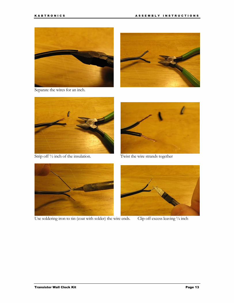
Separate the wires for an inch.
Strip off ½ inch of the insulation. Twist the wire strands together
Use soldering iron to tin (coat with solder) the wire ends. Clip off excess leaving ¼ inch
K A B T R O N I C S A S S E M B L Y I N S T R U C T I O N S
Transistor Wall Clock Kit Page 14
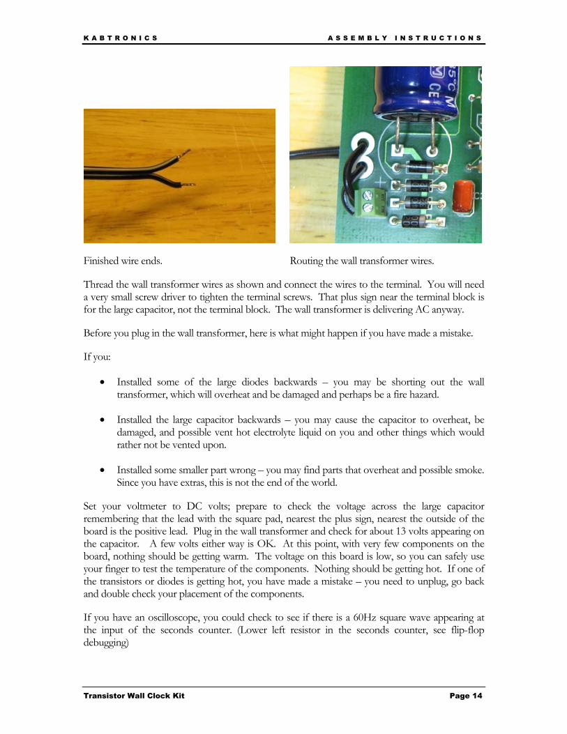
Finished wire ends. Routing the wall transformer wires.
Thread the wall transformer wires as shown and connect the wires to the terminal. You will need a very small screw driver to tighten the terminal screws. That plus sign near the terminal block is for the large capacitor, not the terminal block. The wall transformer is delivering AC anyway.
Before you plug in the wall transformer, here is what might happen if you have made a mistake.
If you:
• Installed some of the large diodes backwards – you may be shorting out the wall transformer, which will overheat and be damaged and perhaps be a fire hazard.
• Installed the large capacitor backwards – you may cause the capacitor to overheat, be damaged, and possible vent hot electrolyte liquid on you and other things which would rather not be vented upon.
• Installed some smaller part wrong – you may find parts that overheat and possible smoke. Since you have extras, this is not the end of the world.
Set your voltmeter to DC volts; prepare to check the voltage across the large capacitor remembering that the lead with the square pad, nearest the plus sign, nearest the outside of the board is the positive lead. Plug in the wall transformer and check for about 13 volts appearing on the capacitor. A few volts either way is OK. At this point, with very few components on the board, nothing should be getting warm. The voltage on this board is low, so you can safely use your finger to test the temperature of the components. Nothing should be getting hot. If one of the transistors or diodes is getting hot, you have made a mistake – you need to unplug, go back and double check your placement of the components.
If you have an oscilloscope, you could check to see if there is a 60Hz square wave appearing at the input of the seconds counter. (Lower left resistor in the seconds counter, see flip-flop debugging)

K A B T R O N I C S A S S E M B L Y I N S T R U C T I O N S
Transistor Wall Clock Kit Page 15
That is the end of the Power supply instructions. Your board should look something like this.
Build the rest of the clock The suggested build order is;
• Assemble Prescaler • Assemble Seconds Chain • Assemble Display • Test the Seconds Chain • Assemble Tens of Second Chain • Assemble Minutes Chain • Assemble Tens of Minutes Chain • Assemble Hours Chain • Final Tests
The following instructions will walk you through the rest of the assembly. If you are experienced with electronics and building kits, you may want to just load all components and hope it all works, I have had success with that method.
K A B T R O N I C S A S S E M B L Y I N S T R U C T I O N S
Transistor Wall Clock Kit Page 16
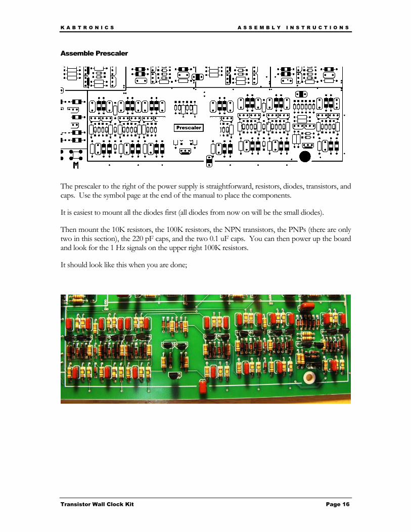
Assemble Prescaler
The prescaler to the right of the power supply is straightforward, resistors, diodes, transistors, and caps. Use the symbol page at the end of the manual to place the components.
It is easiest to mount all the diodes first (all diodes from now on will be the small diodes).
Then mount the 10K resistors, the 100K resistors, the NPN transistors, the PNPs (there are only two in this section), the 220 pF caps, and the two 0.1 uF caps. You can then power up the board and look for the 1 Hz signals on the upper right 100K resistors.
It should look like this when you are done;
K A B T R O N I C S A S S E M B L Y I N S T R U C T I O N S
Transistor Wall Clock Kit Page 17
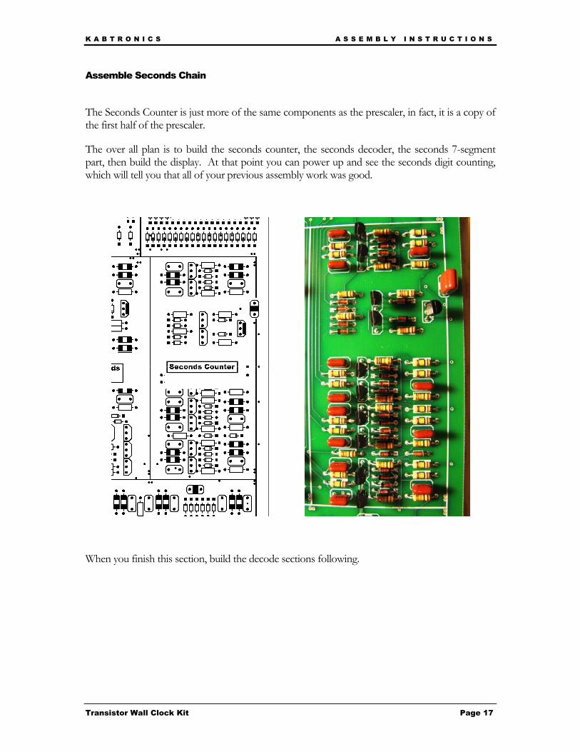
Assemble Seconds Chain
The Seconds Counter is just more of the same components as the prescaler, in fact, it is a copy of the first half of the prescaler.
The over all plan is to build the seconds counter, the seconds decoder, the seconds 7-segment part, then build the display. At that point you can power up and see the seconds digit counting, which will tell you that all of your previous assembly work was good.
When you finish this section, build the decode sections following.
K A B T R O N I C S A S S E M B L Y I N S T R U C T I O N S
Transistor Wall Clock Kit Page 18
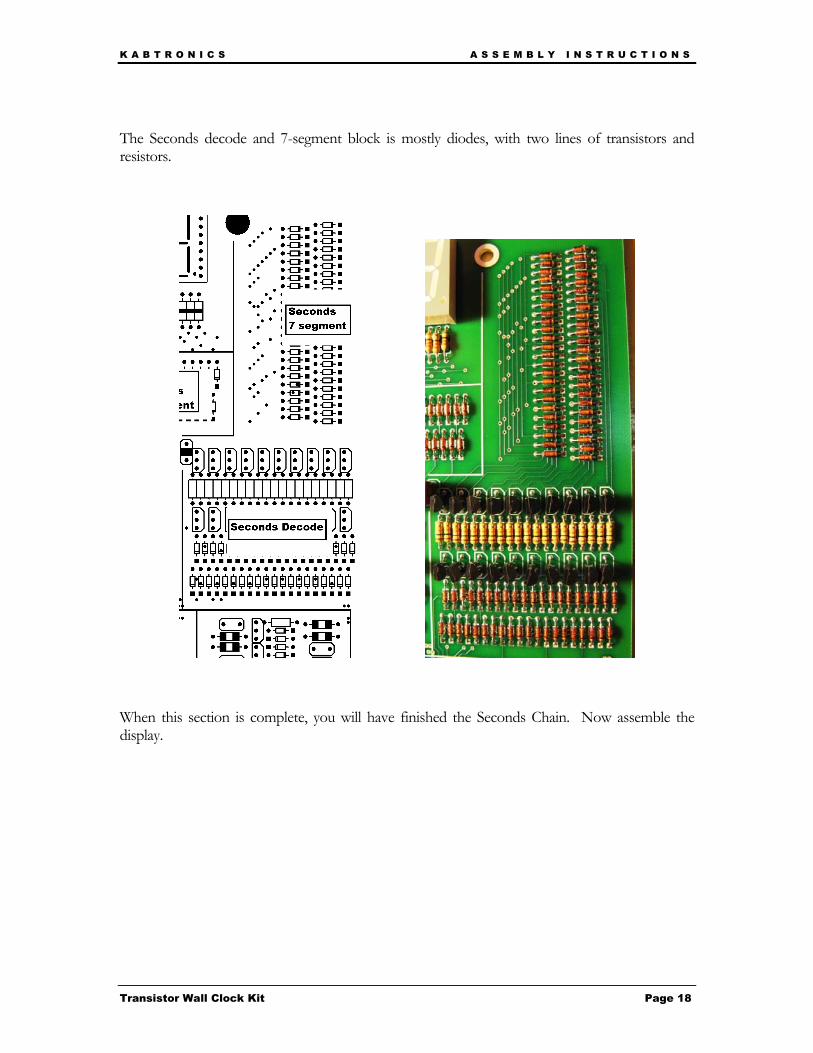
The Seconds decode and 7-segment block is mostly diodes, with two lines of transistors and resistors.
When this section is complete, you will have finished the Seconds Chain. Now assemble the display.
K A B T R O N I C S A S S E M B L Y I N S T R U C T I O N S
Transistor Wall Clock Kit Page 19
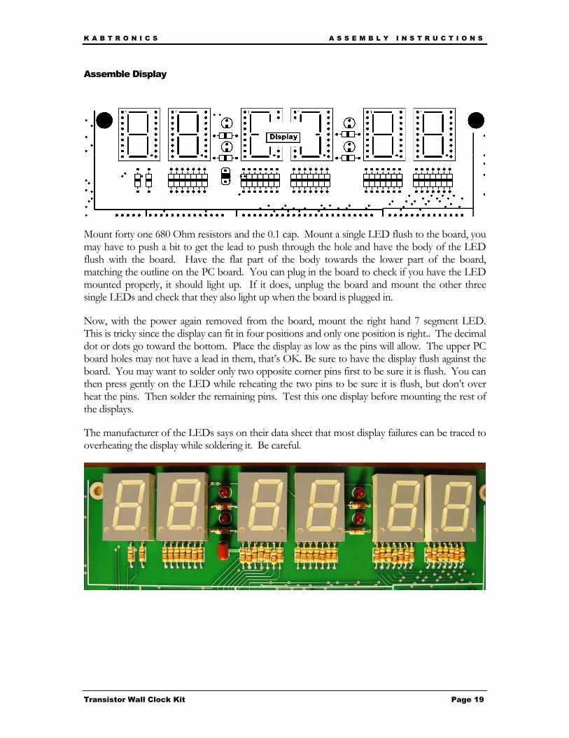
Assemble Display
Mount forty one 680 Ohm resistors and the 0.1 cap. Mount a single LED flush to the board, you may have to push a bit to get the lead to push through the hole and have the body of the LED flush with the board. Have the flat part of the body towards the lower part of the board, matching the outline on the PC board. You can plug in the board to check if you have the LED mounted properly, it should light up. If it does, unplug the board and mount the other three single LEDs and check that they also light up when the board is plugged in.
Now, with the power again removed from the board, mount the right hand 7 segment LED. This is tricky since the display can fit in four positions and only one position is right.. The decimal dot or dots go toward the bottom. Place the display as low as the pins will allow. The upper PC board holes may not have a lead in them, that’s OK. Be sure to have the display flush against the board. You may want to solder only two opposite corner pins first to be sure it is flush. You can then press gently on the LED while reheating the two pins to be sure it is flush, but don’t over heat the pins. Then solder the remaining pins. Test this one display before mounting the rest of the displays.
The manufacturer of the LEDs says on their data sheet that most display failures can be traced to overheating the display while soldering it. Be careful.

K A B T R O N I C S A S S E M B L Y I N S T R U C T I O N S
Transistor Wall Clock Kit Page 20
Test the Seconds Chain and finish the display. Plug in the board, and observe it count from 0 to 9 on one second intervals. This is the Seconds Chain in operation. You may see the first few counts be odd non-numeric figures, that’s OK, it should start counting 0-9 repeatedly after stabilizing. If this is working, mount the remaining displays as carefully as the first display.
If you don’t see it counting from 0 to 9 incrementing each second, stop assembly and go to the “In Case Of Difficulty” section. If it is counting but skipping a few counts, you can elect to continue and debug the problem later.
Assemble Tens of Second Chain Build the Tens of Seconds chain, plug in the board and watch the clock count the seconds 0 – 59.
Assemble Minutes Chain Build the Minutes chain and also mount the two time setting switches near the power supply. When you press the M switch, the input to the Minutes section is connected to a 2 Hz signal. It is better to watch it count at 2 Hz than once per minute.
Assemble Tens of Minutes Chain Build the Tens of Minutes chain, which is a copy of the tens of Seconds chain. Use the M switch to check if it works.
Assemble Hours Chain Build the Hours chain. Use the H switch to have it count quickly thru 1 -12.
Final Tests When the board is powered up, some of the counters can start in illegal states, such as 15 O’clock and 7C minutes, but the counters will count out of bad states and into legal times. Use the M and H switches to cycle the counters and stop at the correct time.
On your first power up testing, carefully watch each digit to be sure all counts are counted, 0-9 on seconds and minutes, 0-5 on tens of seconds and tens of minutes, and 1-12 on hours. Use the H and M switches, otherwise this test would take 12 hours to complete.
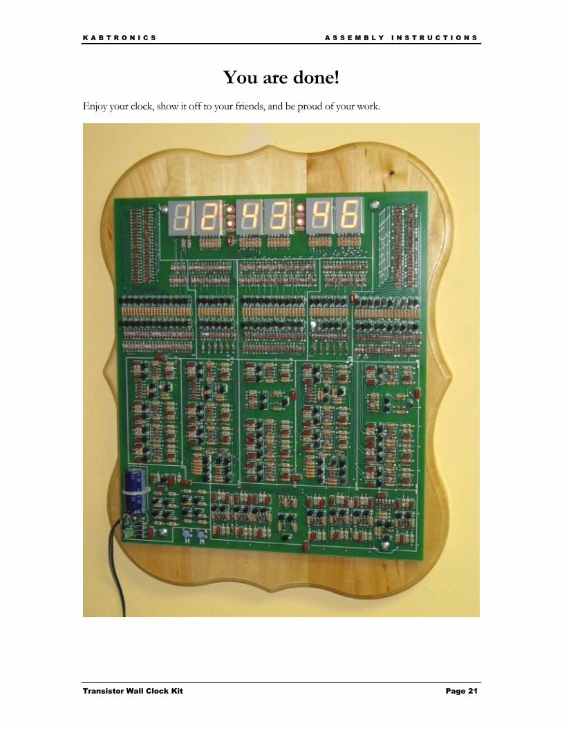
Optionally Mount the Clock on a Plaque
If you have a wall plaque, use four non-conducting standoffs and screw the clock to the plaque with the four screws through the four mounting holes. I recommend drilling pilot holes for the screws.
K A B T R O N I C S A S S E M B L Y I N S T R U C T I O N S
Transistor Wall Clock Kit Page 21
You are done! Enjoy your clock, show it off to your friends, and be proud of your work.

K A B T R O N I C S P A R T S I D E N T I F I C A T I O N
Transistor Wall Clock Kit Page 22
Parts Identification Resistors
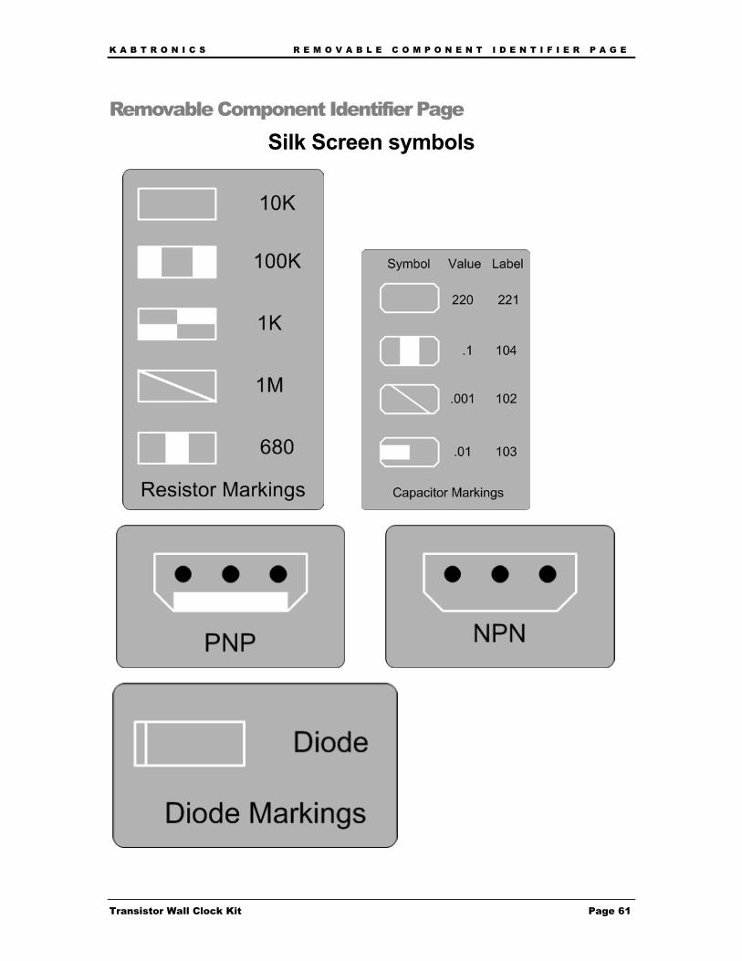
Resistors can be identified by the color bands as shown in the adjacent chart. These parts can be placed in either direction on the board, they are not polarized.
Poly Capacitors
Poly capacitors are not polarized; place them either way on the board. You may receive these parts loose in bulk, or mounted on a section of tape.

K A B T R O N I C S P A R T S I D E N T I F I C A T I O N
Transistor Wall Clock Kit Page 23
Electrolytic capacitors
Electrolytic capacitors have the value printed on them. These are polarized parts; you must place them in the proper position on the board. There is only one of these on the board – in the power supply section. Follow the instructions carefully when mounting this part.
Diodes
The diodes come loose in a bag or on paper strips shown above. There are two sizes, small and large. The large diodes are used in the Power Supply section only. Diodes are polarized; the line on the component needs to match the line on the PC board symbol. Diodes can be damaged by overheating them during soldering, so be quick about it, but do heat the joint enough to make a good solder joint.
Transistors
Transistors come in two types NPN and PNP. There is a number on the package - 3904 is an NPN type and 3906 is a PNP type. You have a lot more NPN than PNP in this kit. Transistors come either loose in a bag or on paper strips.
The paper strips are handy since after you clip out the transistor, the leads are space perfectly for mounting, with the loose transistors, you have to spread the leads.
Transistors are also sensitive to overheating
K A B T R O N I C S P A R T S I D E N T I F I C A T I O N
Transistor Wall Clock Kit Page 24
during soldering so be quick when soldering them. LEDs
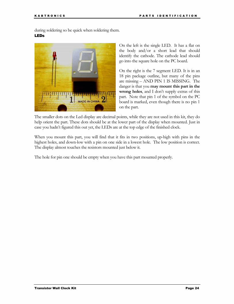
On the left is the single LED. It has a flat on the body and/or a short lead that should identify the cathode. The cathode lead should go into the square hole on the PC board.
On the right is the 7 segment LED. It is in an 18 pin package outline, but many of the pins are missing – AND PIN 1 IS MISSING. The danger is that you may mount this part in the wrong holes, and I don’t supply extras of this part. Note that pin 1 of the symbol on the PC board is marked, even though there is no pin 1 on the part.
The smaller dots on the Led display are decimal points, while they are not used in this kit, they do help orient the part. These dots should be at the lower part of the display when mounted. Just in case you hadn’t figured this out yet, the LEDs are at the top edge of the finished clock.
When you mount this part, you will find that it fits in two positions, up-high with pins in the highest holes, and down-low with a pin on one side in a lowest hole. The low position is correct. The display almost touches the resistors mounted just below it.
The hole for pin one should be empty when you have this part mounted properly.
K A B T R O N I C S T H E O R Y O F O P E R A T I O N
Transistor Wall Clock Kit Page 25
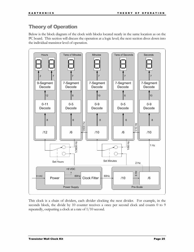
Theory of Operation Below is the block diagram of the clock with blocks located nearly in the same location as on the PC board. This section will discuss the operation at a logic level; the next section dives down into the individual transistor level of operation.
This clock is a chain of dividers, each divider clocking the next divider. For example, in the seconds block, the divide by 10 counter receives a once per second clock and counts 0 to 9 repeatedly, outputting a clock at a rate of 1/10 second.
K A B T R O N I C S T H E O R Y O F O P E R A T I O N
Transistor Wall Clock Kit Page 26
Count
“Bit” or flip-flop or output, and (value)
Q3 Q2 Q1 Q0 (8) (4) (2) (1)
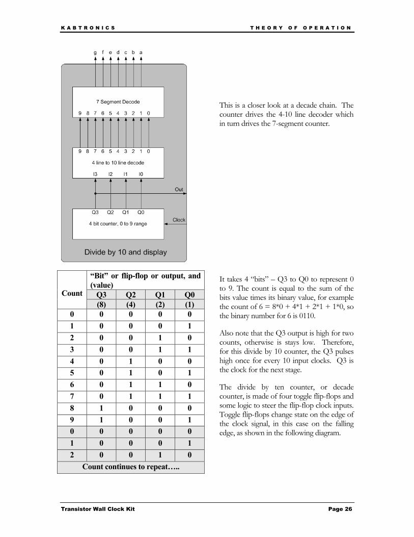
0 0 0 0 0 1 0 0 0 1 2 0 0 1 0 3 0 0 1 1 4 0 1 0 0 5 0 1 0 1 6 0 1 1 0 7 0 1 1 1 8 1 0 0 0 9 1 0 0 1 0 0 0 0 0 1 0 0 0 1 2 0 0 1 0
Count continues to repeat…..
This is a closer look at a decade chain. The counter drives the 4-10 line decoder which in turn drives the 7-segment counter.
It takes 4 “bits” – Q3 to Q0 to represent 0 to 9. The count is equal to the sum of the bits value times its binary value, for example the count of 6 = 8*0 + 4*1 + 2*1 + 1*0, so the binary number for 6 is 0110.
Also note that the Q3 output is high for two counts, otherwise is stays low. Therefore, for this divide by 10 counter, the Q3 pulses high once for every 10 input clocks. Q3 is the clock for the next stage.
The divide by ten counter, or decade counter, is made of four toggle flip-flops and some logic to steer the flip-flop clock inputs. Toggle flip-flops change state on the edge of the clock signal, in this case on the falling edge, as shown in the following diagram.
K A B T R O N I C S T H E O R Y O F O P E R A T I O N
Transistor Wall Clock Kit Page 27
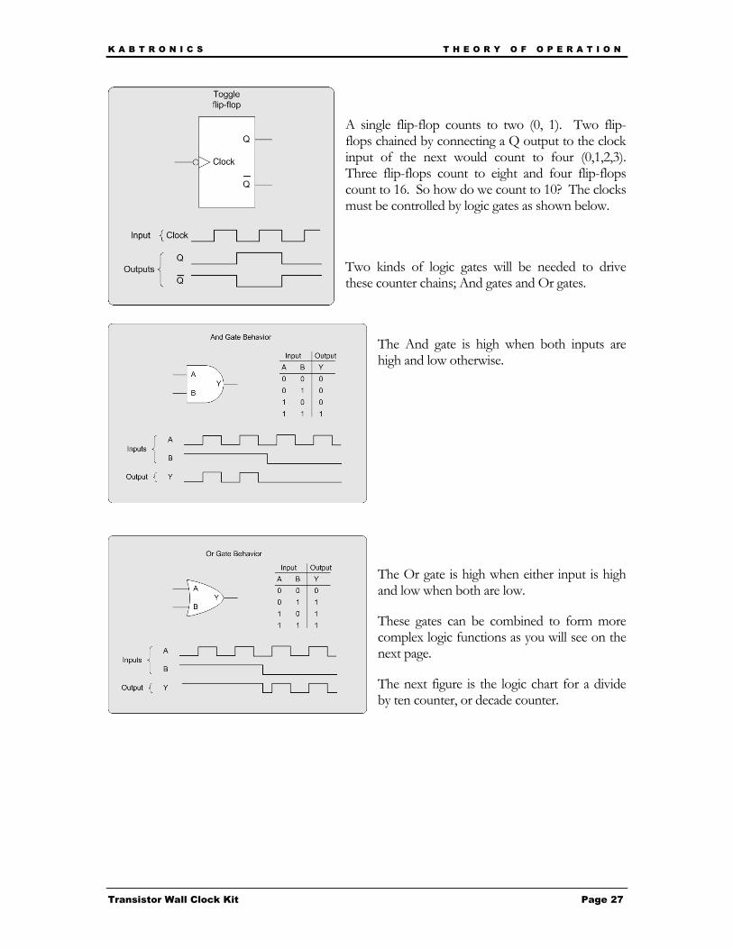
A single flip-flop counts to two (0, 1). Two flip-flops chained by connecting a Q output to the clock input of the next would count to four (0,1,2,3). Three flip-flops count to eight and four flip-flops count to 16. So how do we count to 10? The clocks must be controlled by logic gates as shown below.
Two kinds of logic gates will be needed to drive these counter chains; And gates and Or gates.
The And gate is high when both inputs are high and low otherwise.
The Or gate is high when either input is high and low when both are low.
These gates can be combined to form more complex logic functions as you will see on the next page.
The next figure is the logic chart for a divide by ten counter, or decade counter.

K A B T R O N I C S T H E O R Y O F O P E R A T I O N
Transistor Wall Clock Kit Page 28
Looking at the logic chart, you can see that the clock for the Q0 flip-flop can be a direct connection to the input clock to the decade counter. Also, the clock for the Q2 flip-flop can be a direct connection to Q1.
The clock for the Q1 flip-flop is very similar to the Q0 output, but one pulse at the 9 count needs to be removed, or masked, at the count of 9. Using an And gate with Q0 and the inverse of Q3 does the trick.
The clock for the Q3 flip-flop, which is the bottom line of the figure above, looks like Q2 for the first 8 counts (0-7) and Q0 for counts 8 and 9. A selector driven by Q3 does this.
The 4 to 10 line decoder uses Q0 to Q3, and their inverses, to select one of the ten output lines.
K A B T R O N I C S T H E O R Y O F O P E R A T I O N
Transistor Wall Clock Kit Page 29
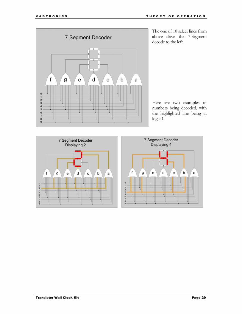
The one of 10 select lines from above drive the 7-Segment decode to the left.
Here are two examples of numbers being decoded, with the highlighted line being at logic 1.
K A B T R O N I C S T H E O R Y O F O P E R A T I O N
Transistor Wall Clock Kit Page 30
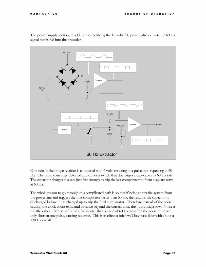
The power supply section, in addition to rectifying the 12 volts AC power, also extracts the 60 Hz signal that is fed into the prescaler.
One side of the bridge rectifier is compared with 6 volts resulting in a pulse train repeating at 60 Hz. The pulse train edge detected and drives a switch that discharges a capacitor at a 60 Hz rate. The capacitor charges at a rate just fast enough to trip the last comparator to form a square wave at 60 Hz.
The whole reason to go through this complicated path is so that if noise enters the system from the power line and triggers the first comparator faster than 60 Hz, the result is the capacitor is discharged before it has charged up to trip the final comparator. Therefore instead of the noise causing the clock count extra and advance beyond the correct time, the output stays low. Noise is usually a short term set of pulses, far shorter than a cycle of 60 Hz, so often the noise pulse will only shorten one pulse, causing no error. This is in effect a brick wall low pass filter with about a 120 Hz cutoff.
K A B T R O N I C S C I R C U I T D E S C R I P T I O N
Transistor Wall Clock Kit Page 31
Circuit Description The previous section described the clock functionality at the logic level; this section will descend to the transistor level.
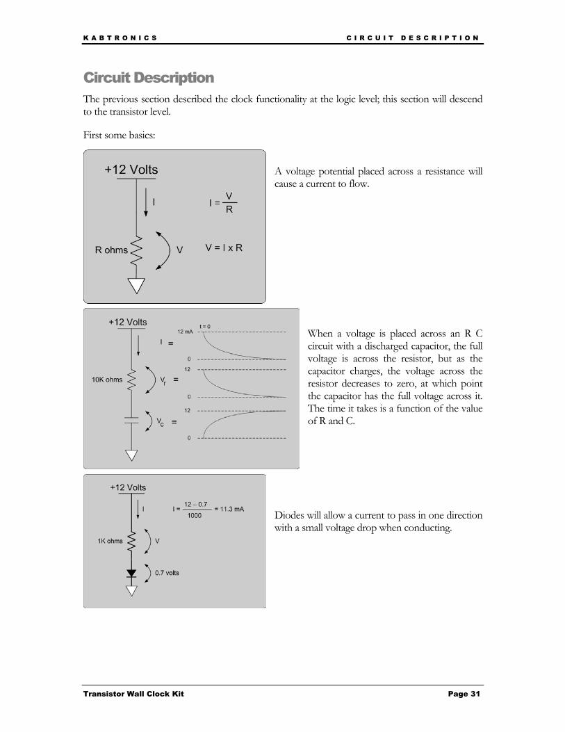
First some basics:
A voltage potential placed across a resistance will cause a current to flow.
When a voltage is placed across an R C circuit with a discharged capacitor, the full voltage is across the resistor, but as the capacitor charges, the voltage across the resistor decreases to zero, at which point the capacitor has the full voltage across it. The time it takes is a function of the value of R and C.
Diodes will allow a current to pass in one direction with a small voltage drop when conducting.
K A B T R O N I C S C I R C U I T D E S C R I P T I O N
Transistor Wall Clock Kit Page 32
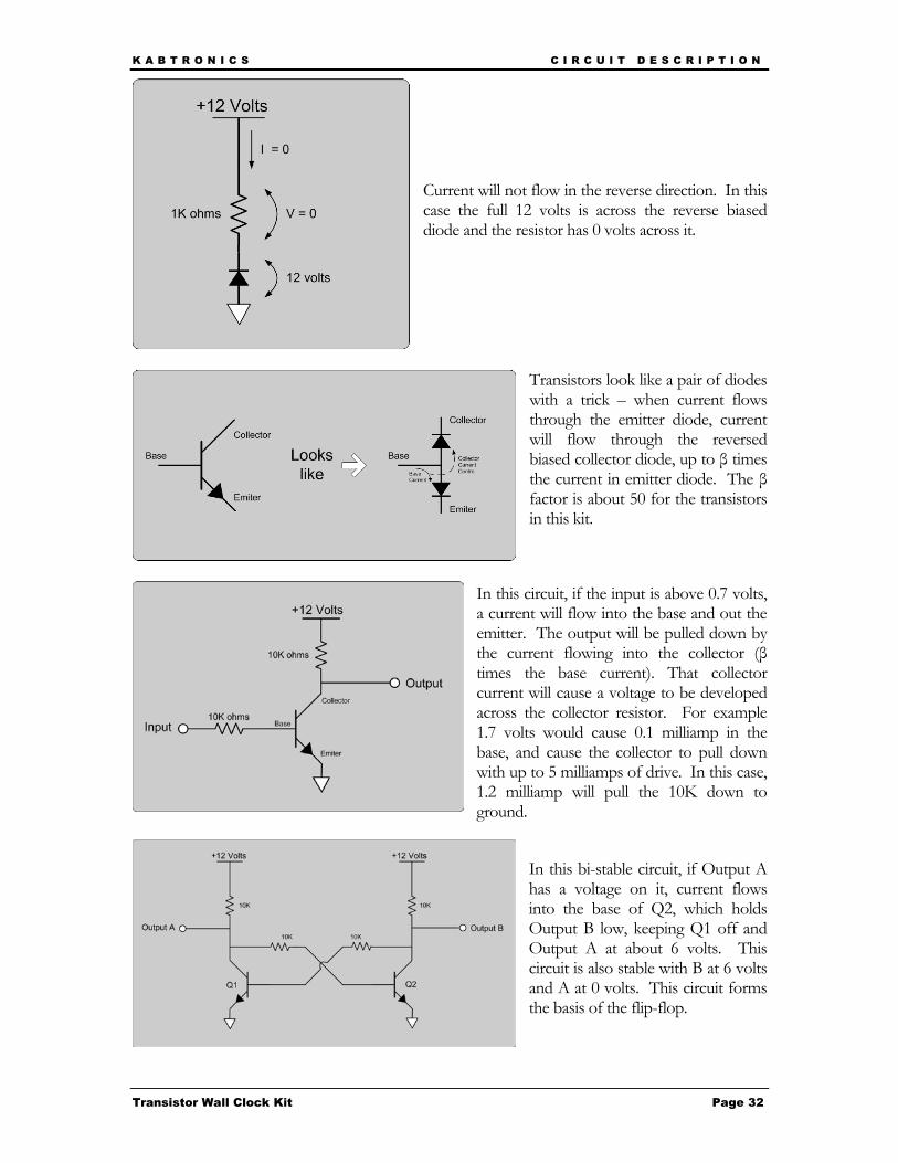
Current will not flow in the reverse direction. In this case the full 12 volts is across the reverse biased diode and the resistor has 0 volts across it.
Transistors look like a pair of diodes with a trick – when current flows through the emitter diode, current will flow through the reversed biased collector diode, up to β times the current in emitter diode. The β factor is about 50 for the transistors in this kit.
In this circuit, if the input is above 0.7 volts, a current will flow into the base and out the emitter. The output will be pulled down by the current flowing into the collector (β times the base current). That collector current will cause a voltage to be developed across the collector resistor. For example 1.7 volts would cause 0.1 milliamp in the base, and cause the collector to pull down with up to 5 milliamps of drive. In this case, 1.2 milliamp will pull the 10K down to ground.
In this bi-stable circuit, if Output A has a voltage on it, current flows into the base of Q2, which holds Output B low, keeping Q1 off and Output A at about 6 volts. This circuit is also stable with B at 6 volts and A at 0 volts. This circuit forms the basis of the flip-flop.
K A B T R O N I C S C I R C U I T D E S C R I P T I O N
Transistor Wall Clock Kit Page 33
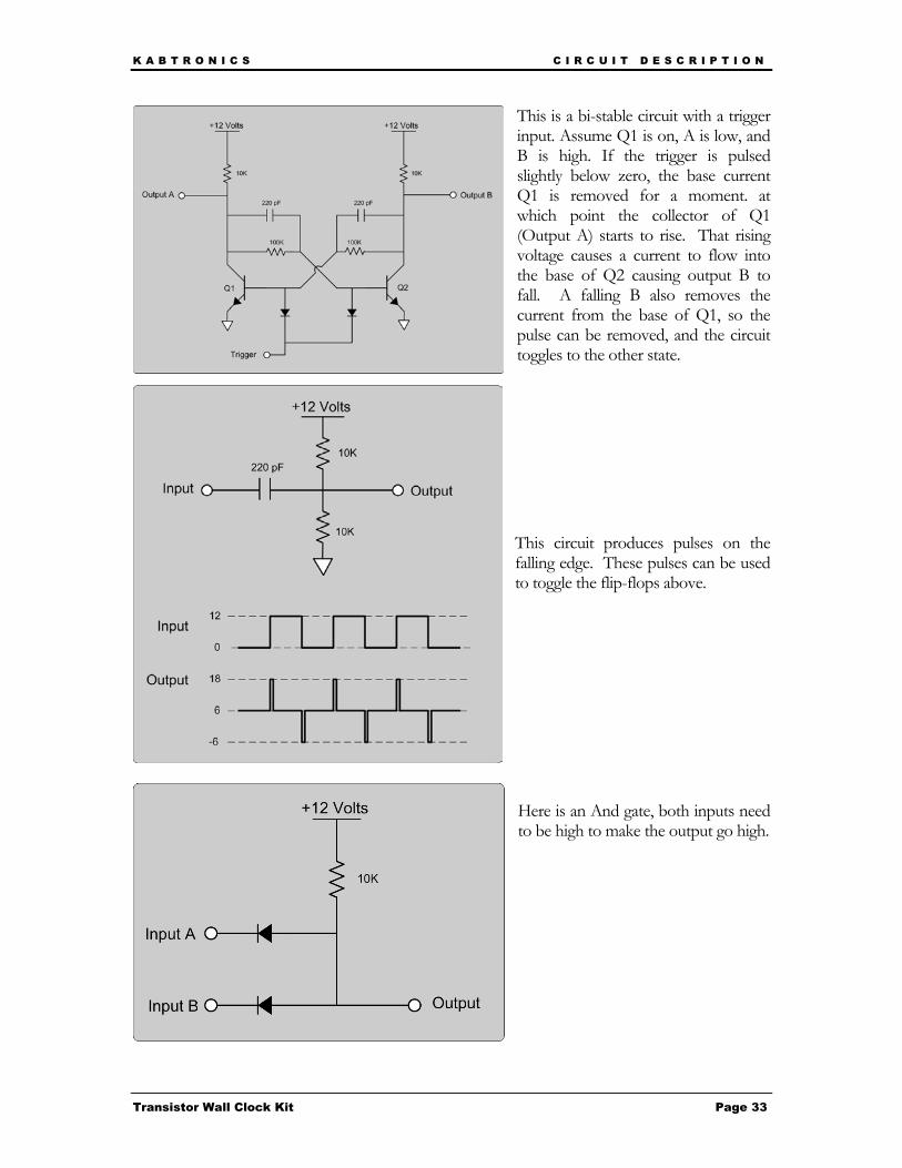
This is a bi-stable circuit with a trigger input. Assume Q1 is on, A is low, and B is high. If the trigger is pulsed slightly below zero, the base current Q1 is removed for a moment. at which point the collector of Q1 (Output A) starts to rise. That rising voltage causes a current to flow into the base of Q2 causing output B to fall. A falling B also removes the current from the base of Q1, so the pulse can be removed, and the circuit toggles to the other state.
This circuit produces pulses on the falling edge. These pulses can be used to toggle the flip-flops above.
Here is an And gate, both inputs need to be high to make the output go high.

K A B T R O N I C S C I R C U I T D E S C R I P T I O N
Transistor Wall Clock Kit Page 34
This is an And-Or gate. The output is;
(A and B) or (C and D)
This is used to build the selector in the counter sections.
This is a differential amplifier. Assume A is at 5 volts and B is at 6 volts. The emitters are at 5.6 volts, transistor A is on, all the current from the resistor (0.64 mA) flows through collector A and none flows through collector B.
Assume A is at 5 volts. B is at 6 volts, the emitter current flows through Q1 and Q3. Q2 and Q4 are off. As input A rises, when is reaches 6 volts, the emitter current switches to Q2, turning on Q4, which slightly lowers point B. This feedback snaps the comparator into the new state. Q3 turns off providing the output.
K A B T R O N I C S C I R C U I T D E S C R I P T I O N
Transistor Wall Clock Kit Page 35
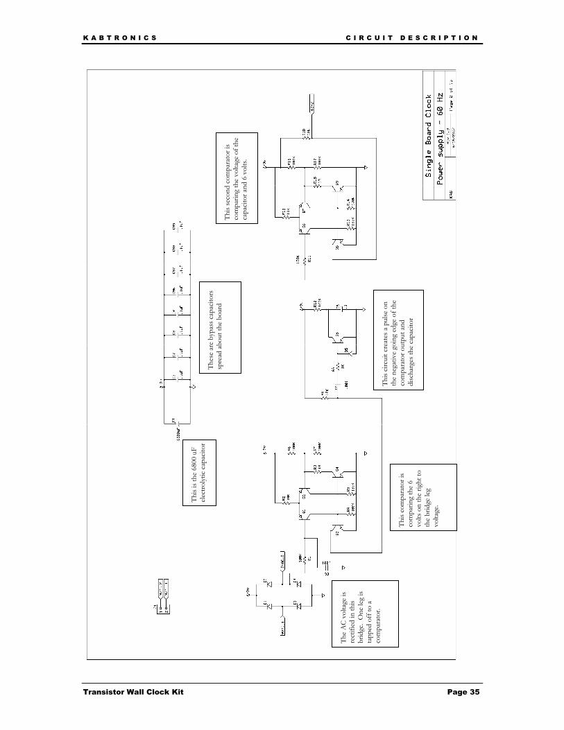
The
AC
volta
ge is
re
ctifi
ed in
this
brid
ge.
One
leg
is ta
pped
off
to a
co
mpa
rato
r.
This
com
para
tor i
s co
mpa
ring
the
6 vo
lts o
n th
e rig
ht to
th
e br
idge
leg
volta
ge.
This
circu
it cr
eate
s a p
ulse
on
the
nega
tive
goin
g ed
ge o
f the
co
mpa
rato
r out
put a
nd
disc
harg
es th
e ca
pacit
or
This
seco
nd c
ompa
rato
r is
com
parin
g th
e vo
ltage
of t
he
capa
citor
and
6 v
olts
.
Thes
e ar
e by
pass
cap
acito
rs
spre
ad a
bout
the
boar
d
This
is th
e 68
00 u
F el
ectro
lytic
capa
citor
K A B T R O N I C S C I R C U I T D E S C R I P T I O N
Transistor Wall Clock Kit Page 36
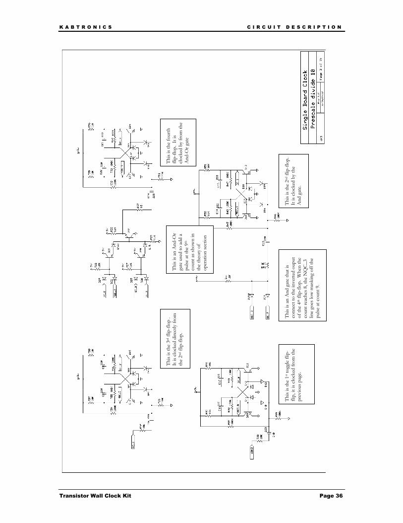
This
is th
e 1s
t tog
gle
flip-
flip,
it is
clo
cked
from
the
prev
ious
pag
e.
This
is an
And
gat
e th
at is
co
nnec
t to
the
inve
rted
oupu
t of
the
4th f
lip-fl
op.
Whe
n th
e co
unt r
each
es 8
, the
NQ
C_3
line
goes
low
mas
king
off
the
pulse
at c
ount
9.
This
is th
e 2n
d flip
-flo
p.
It is
cloc
ked
by th
e A
nd g
ate.
This
is th
e 3r
d flip
-flop
.
It is
clo
cked
dire
ctly
from
th
e 2n
d flip
-flop
. Th
is is
an A
nd-O
r ga
te u
sed
to a
dd a
pu
lse a
t the
9th
co
unt a
s sho
wn
in
the
theo
ry o
f op
erat
ion
sect
ion
This
is th
e fo
urth
fli
p-flo
p. I
t is
clock
ed b
y fr
om th
e A
nd-O
r gat
e
K A B T R O N I C S C I R C U I T D E S C R I P T I O N
Transistor Wall Clock Kit Page 37
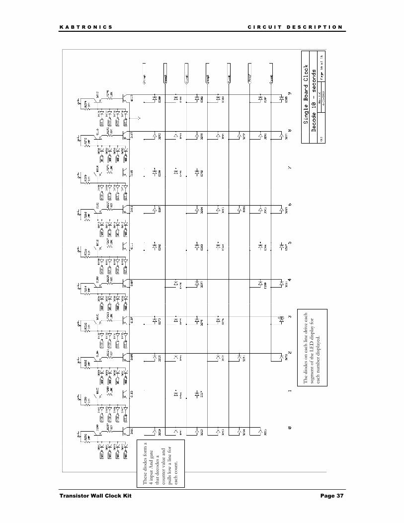
Thes
e di
odes
form
a
4 in
put A
nd g
ate
that
dec
odes
a
coun
ter v
alue
and
pulls
low
a li
ne fo
r ea
ch c
ount
.
The
diod
es o
n ea
ch li
ne d
rive
each
se
gmen
t of t
he L
ED
disp
lay fo
r ea
ch n
umbe
r disp
layed
.
K A B T R O N I C S I N C A S E O F D I F F I C U L T Y
Transistor Wall Clock Kit Page 38
In Case of Difficulty General Troubleshooting
The most useful tool you have when troubleshooting is your brain.
Start with the data showing the problem. If one of the displays is not counting properly, stop and think about it.
How is it counting? • Is it changing at all? (this will tell you if the input clock is present) • Is it changing at the right rate? (this will tell you if the clock to the counter is at the right
frequency) • Is it going through the proper number of states, even if the numbers displayed are wrong?
(this will hint if the problem is in the decode/display area or the counter) • Is it displaying only proper numbers, or are there odd characters and blanks showing?
(this will hint at problems in 1-of-n decode or 7-segment decode)
A problem in the logic section will cause the counter to cycle in the wrong number of states. A problem in the decode section can feed back to the counter and cause the counter to skip states. A problem in the 7-segment decode should only affect the displayed digits, not the counter. Make a most likely guess at the problem, then gather more data to either support or refute your guess. Repeat until you find the problem. This list is my guess at the cause of any problem in decreasing order of probability;
• Wrong component loaded
• Component loaded backwards
• Bad solder joint causing open or short to adjacent pad
• A clipped-off lead has stuck to the back of the board and is shorting out the circuit
• A trace is broken at the annular ring or along the trace
• The board is resting on something conductive shorting out the circuit
• A component is bad because;
o it was over heated when soldered (medium chance)
o came that way with the kit (low chance)
o was damaged by static electricity when handled (unlikely)
So take a close look at the back of the board looking for bad solder joints and clipped leads in the area of the problem. Check for proper components and orientations. Ohm out traces in the area of trouble. If you haven’t found the problem, continue onto the specific trouble shooting section below, which will walk you through troubleshooting a section.
K A B T R O N I C S I N C A S E O F D I F F I C U L T Y
Transistor Wall Clock Kit Page 39
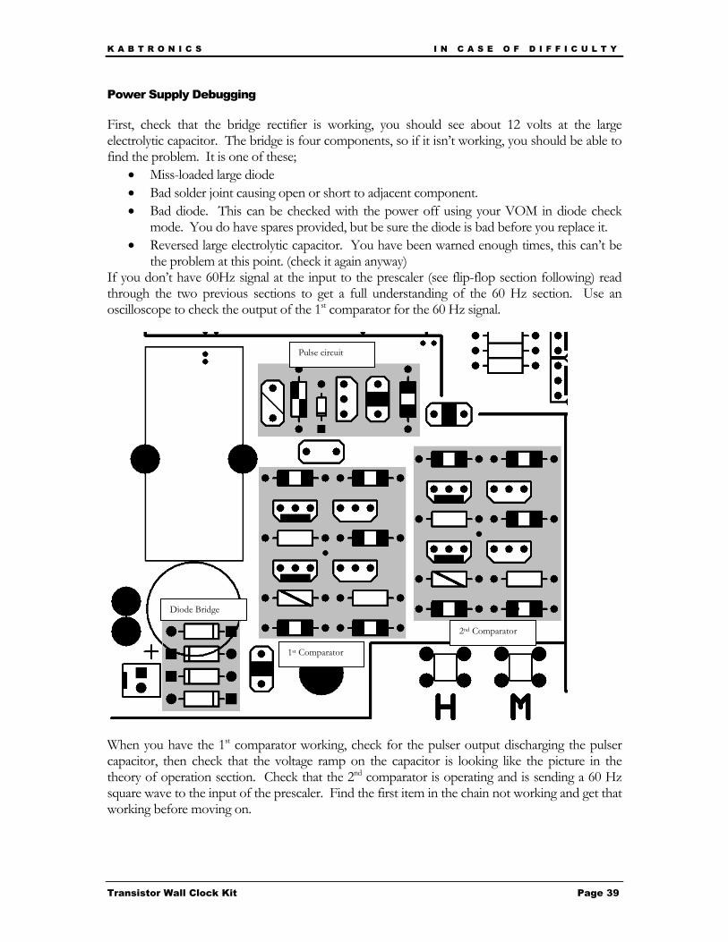
Power Supply Debugging First, check that the bridge rectifier is working, you should see about 12 volts at the large electrolytic capacitor. The bridge is four components, so if it isn’t working, you should be able to find the problem. It is one of these;
• Miss-loaded large diode • Bad solder joint causing open or short to adjacent component. • Bad diode. This can be checked with the power off using your VOM in diode check
mode. You do have spares provided, but be sure the diode is bad before you replace it. • Reversed large electrolytic capacitor. You have been warned enough times, this can’t be
the problem at this point. (check it again anyway) If you don’t have 60Hz signal at the input to the prescaler (see flip-flop section following) read through the two previous sections to get a full understanding of the 60 Hz section. Use an oscilloscope to check the output of the 1st comparator for the 60 Hz signal.
When you have the 1st comparator working, check for the pulser output discharging the pulser capacitor, then check that the voltage ramp on the capacitor is looking like the picture in the theory of operation section. Check that the 2nd comparator is operating and is sending a 60 Hz square wave to the input of the prescaler. Find the first item in the chain not working and get that working before moving on.
Diode Bridge
1st Comparator
2nd Comparator
Pulse circuit
K A B T R O N I C S I N C A S E O F D I F F I C U L T Y
Transistor Wall Clock Kit Page 40
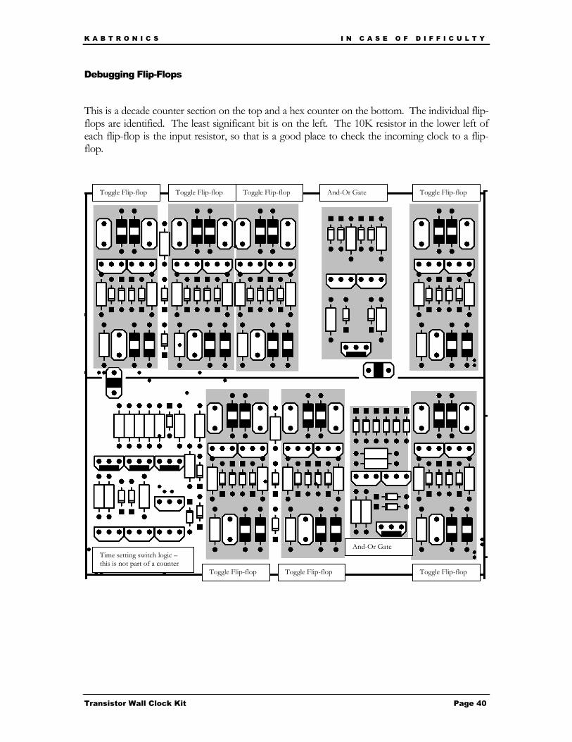
Debugging Flip-Flops
This is a decade counter section on the top and a hex counter on the bottom. The individual flip-flops are identified. The least significant bit is on the left. The 10K resistor in the lower left of each flip-flop is the input resistor, so that is a good place to check the incoming clock to a flip-flop.
add trouble shooting guide
Toggle Flip-flop Toggle Flip-flop Toggle Flip-flop Toggle Flip-flop
Toggle Flip-flop Toggle Flip-flop Toggle Flip-flop
And-Or Gate
And-Or GateTime setting switch logic – this is not part of a counter
K A B T R O N I C S I N C A S E O F D I F F I C U L T Y
Transistor Wall Clock Kit Page 41
The basics of flip-flop troubleshooting are;
• Find the last working flip-flop in the chain.
• Check if the input to the bad flip-flop is toggling. The input to each flip-flop on the 10K resistor on the lower left of a flip-flop.
• Check if the components are correctly placed and oriented.
• Check if the solder joints are good and that there isn’t excess solder or leads shorting out the circuit on the bottom.
• Check if the decoder circuit being driven by this flip-flop is correct, a problem in the decoder can affect the flip-flop. Really check this out, if it isn’t one of the above problems, you are running out of possibilities.
If you haven’t found the problem by this point, you will need to use your oscilloscope to compare a working flip-flop with the bad flip flop. Look at the base of each transistor to see if the voltage is looking normal. (You can see normal from the working flip-flop). There aren’t many other nodes in a flip-flop, the outputs, the bases, and the output of the pulser feeding the toggle diodes.
You will find that the flip-flops are very sensitive, touching an output with your scope lead can trigger the flip-flop to change, at first you may not realizes that and think that both outputs are low, when in fact the flip-flop is changing as you move the scope lead. Also, this sensitivity can be an issue when you are handling the board during testing, it can be affected by your fingers. You can’t hurt the circuit, but it may not count right while you are touching the board.
If the display is changing with each count, but the value is wrong, for example the counter is counting 2,5,2,5 or 0,1,2,blank,0,1,2,blank your problem is probably in the logic section for that counter.
If you just can’t find the problem, start to suspect a bad diode or transistor, the chance is small, but if you have checked everything else you may be out of possibilities. You should be able to spot a bad diode or transistor by bad voltages on one of the nodes, don’t go swapping out parts without seeing some evidence first.
K A B T R O N I C S I N C A S E O F D I F F I C U L T Y
Transistor Wall Clock Kit Page 42
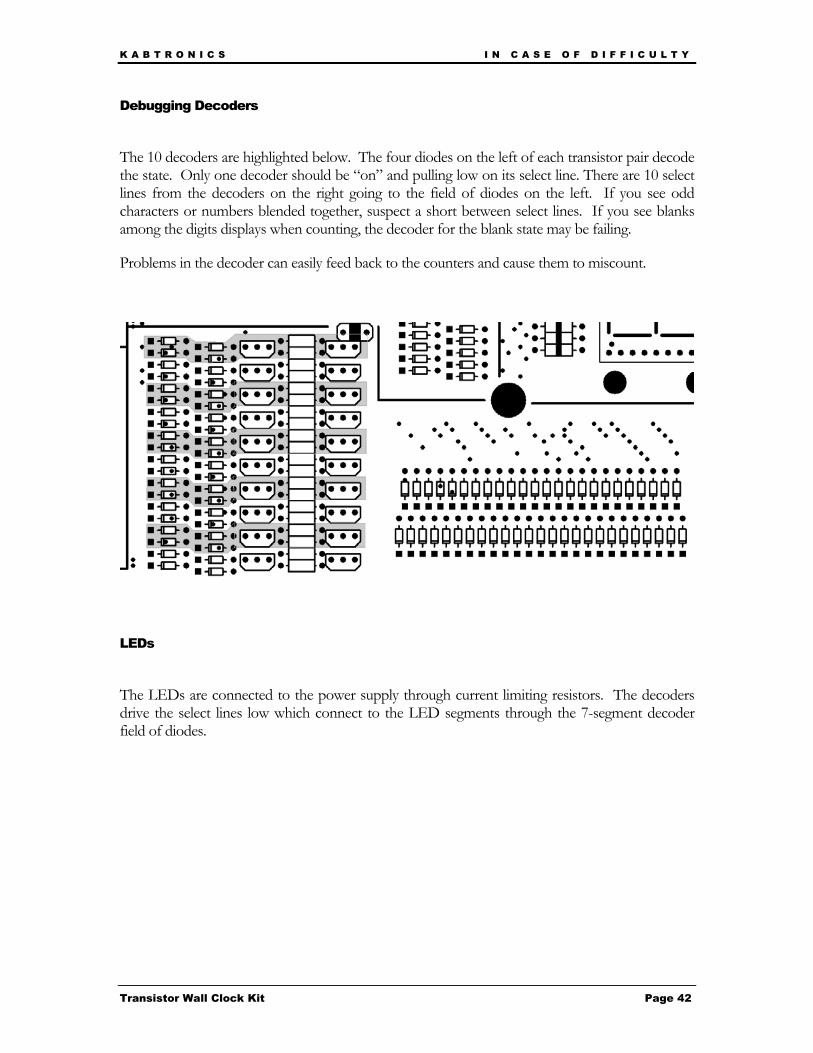
Debugging Decoders
The 10 decoders are highlighted below. The four diodes on the left of each transistor pair decode the state. Only one decoder should be “on” and pulling low on its select line. There are 10 select lines from the decoders on the right going to the field of diodes on the left. If you see odd characters or numbers blended together, suspect a short between select lines. If you see blanks among the digits displays when counting, the decoder for the blank state may be failing.
Problems in the decoder can easily feed back to the counters and cause them to miscount.
LEDs
The LEDs are connected to the power supply through current limiting resistors. The decoders drive the select lines low which connect to the LED segments through the 7-segment decoder field of diodes.
K A B T R O N I C S S P E C I F I C A T I O N S
Transistor Wall Clock Kit Page 43
Specifications
PC board Size: 10 inches wide by 11.3 inches high
(Allow ¼ inch behind board and ¾ inch above when loaded for parts clearance)
Weight: About 14.5 oz, (add 9 oz for wall transformer)
Power consumption: About 5.7 watts, (0.6 amps @ 9.5 volts AC)
Temperature limits: Designed for room temperature operation, 60-80 °F
Longevity: The electrolytic capacitor will eventually dry out as the liquid gradually leaks out the pressure vent, you may need to replace it in 10 or 15 years. The LED displays will gradually grow dimmer, perhaps reaching 50% brightness in 10 or 20 years. The large diodes may fail at some point, they are working hard. Any of these items can be easily replaced by you.
Warrantee: There is no warrantee of any kind. KABtronics wants you to succeed and be happy with your clock, so don’t hesitate to email [email protected] with questions if you are having difficulty.
K A B T R O N I C S C I R C U I T B O A R D V I E W
Transistor Wall Clock Kit Page 44
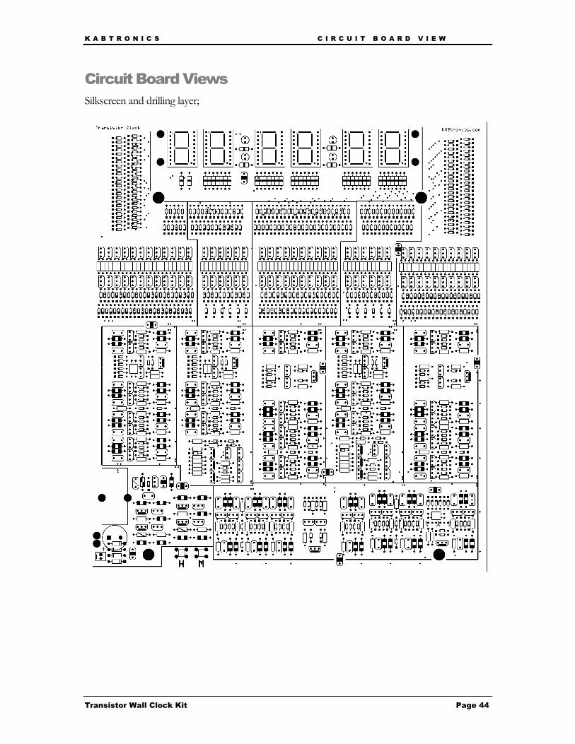
Circuit Board Views Silkscreen and drilling layer;
K A B T R O N I C S C I R C U I T B O A R D V I E W
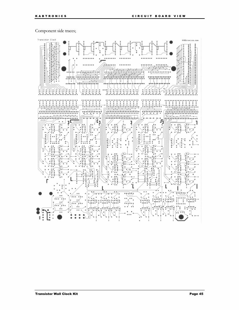
Transistor Wall Clock Kit Page 45
Component side traces;
K A B T R O N I C S S C H E M A T I C
Transistor Wall Clock Kit Page 46
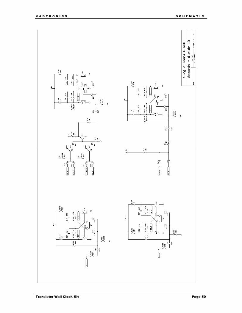
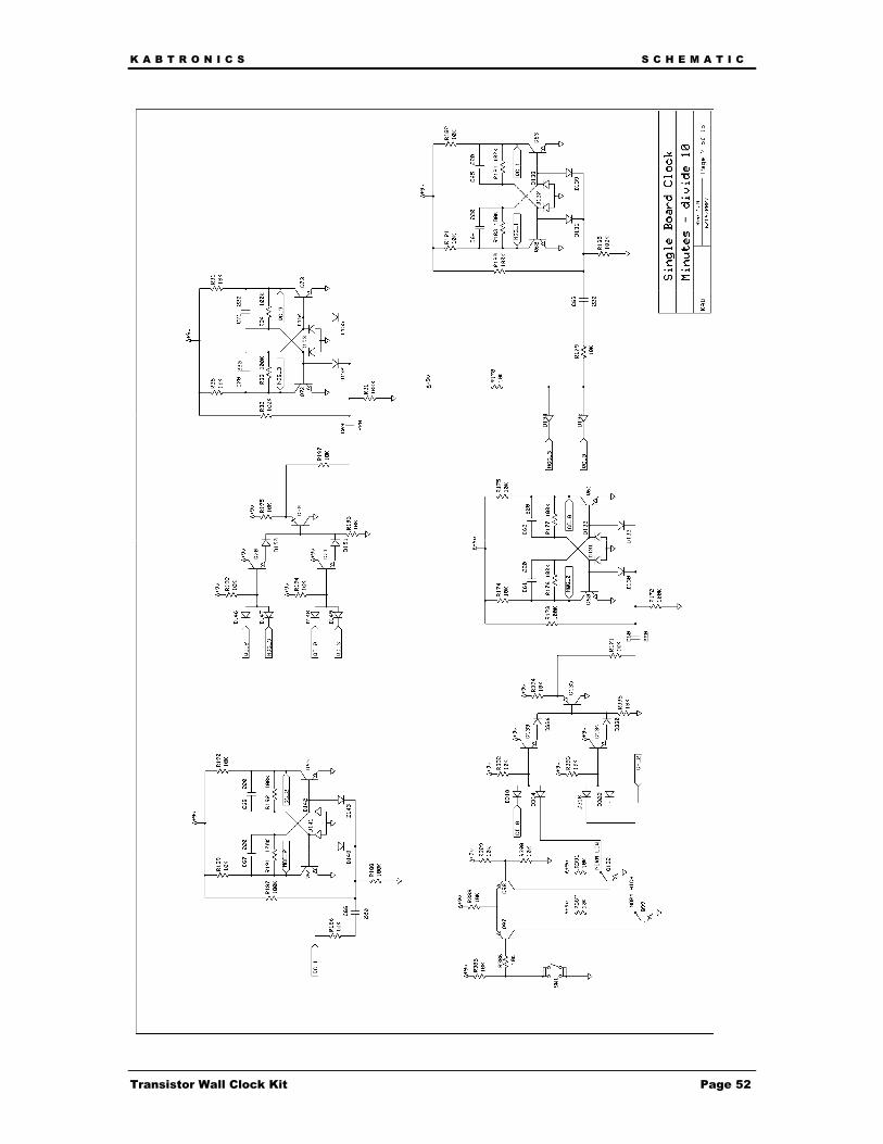
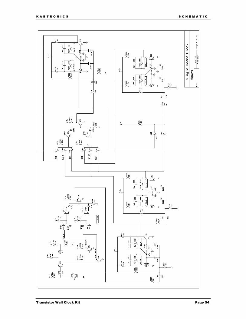
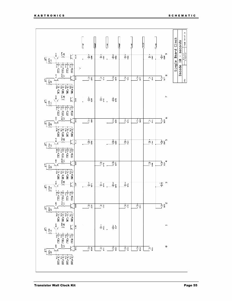
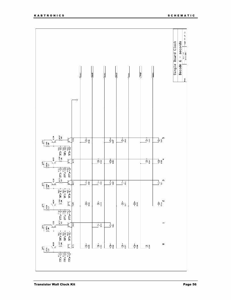
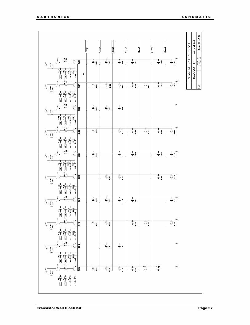
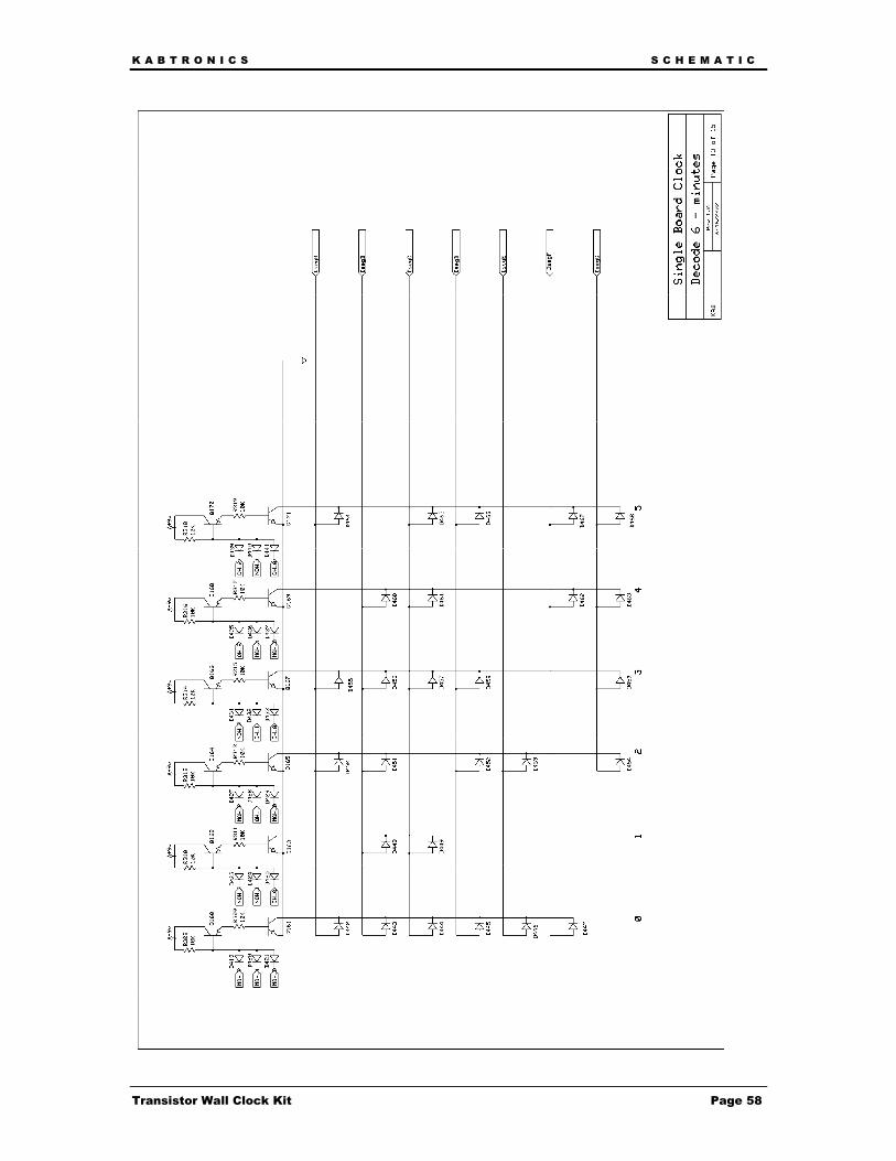
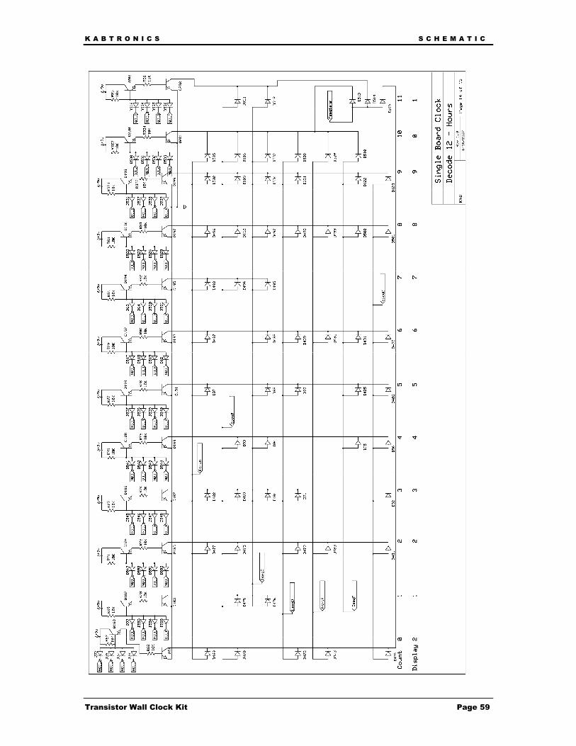
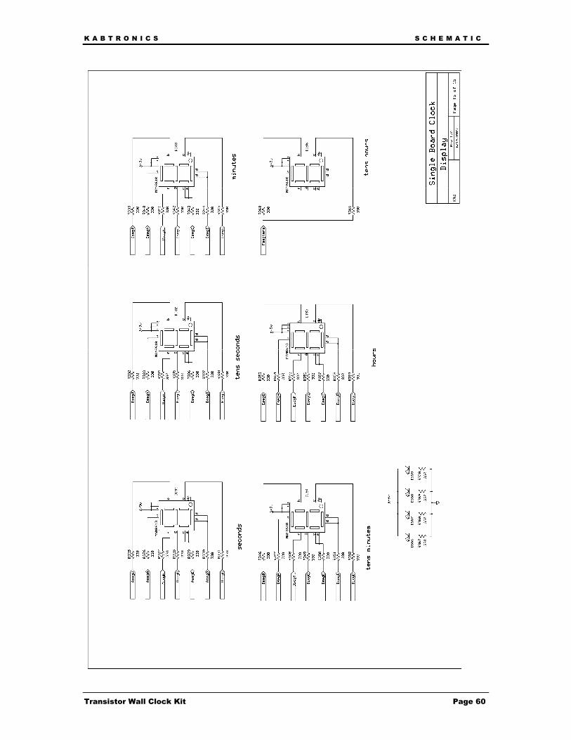
Schematic
K A B T R O N I C S S C H E M A T I C
Transistor Wall Clock Kit Page 47

K A B T R O N I C S S C H E M A T I C
Transistor Wall Clock Kit Page 48
K A B T R O N I C S S C H E M A T I C
Transistor Wall Clock Kit Page 49
K A B T R O N I C S S C H E M A T I C
Transistor Wall Clock Kit Page 50

K A B T R O N I C S S C H E M A T I C
Transistor Wall Clock Kit Page 51
K A B T R O N I C S S C H E M A T I C
Transistor Wall Clock Kit Page 52

K A B T R O N I C S S C H E M A T I C
Transistor Wall Clock Kit Page 53
K A B T R O N I C S S C H E M A T I C
Transistor Wall Clock Kit Page 54
K A B T R O N I C S S C H E M A T I C
Transistor Wall Clock Kit Page 55
K A B T R O N I C S S C H E M A T I C
Transistor Wall Clock Kit Page 56
K A B T R O N I C S S C H E M A T I C
Transistor Wall Clock Kit Page 57
K A B T R O N I C S S C H E M A T I C
Transistor Wall Clock Kit Page 58
K A B T R O N I C S S C H E M A T I C
Transistor Wall Clock Kit Page 59
K A B T R O N I C S S C H E M A T I C
Transistor Wall Clock Kit Page 60
K A B T R O N I C S R E M O V A B L E C O M P O N E N T I D E N T I F I E R P A G E
Transistor Wall Clock Kit Page 61
Removable Component Identifier Page Silk Screen symbols