TransientTransient Conduction Conduction - Faculty of ...mazlan/?download=Heat Transfer Chp 5 -...
19
10/5/2013 1 H E A T T R A N S F E R C H A P T E R 3 Dr Mazlan - SME 4463 HEAT TRANSFER HEAT TRANSFER SME 4463 SME 4463 LECTURER: PM DR MAZLAN ABDUL WAHID http://www.fkm.utm.my/~mazlan H E A T T R A N S F E R C H A P T E R 3 Dr Mazlan - SME 4463 Chapter hapter 5 Transient Transient Conduction Conduction PM Dr Mazlan Abdul Wahid Faculty of Mechanical Engineering Universiti Teknologi Malaysia www.fkm.utm.my/~mazlan
Transcript of TransientTransient Conduction Conduction - Faculty of ...mazlan/?download=Heat Transfer Chp 5 -...
10/5/2013
1
HEAT
TRANSFER
CCCCCCCC
HHHHHHHH
AAAAAAAA
PPPPPPPP
TTTTTTTT
EEEEEEEE
RRRRRRRR
33333333
Dr Mazlan - SME 4463
HEAT TRANSFERHEAT TRANSFERSME 4463SME 4463
LECTURER: PM DR MAZLAN ABDUL WAHIDhttp://www.fkm.utm.my/~mazlan
HEAT
TRANSFER
CCCCCCCC
HHHHHHHH
AAAAAAAA
PPPPPPPP
TTTTTTTT
EEEEEEEE
RRRRRRRR
33333333
Dr Mazlan - SME 4463
CChapter hapter 55
TransientTransient ConductionConduction
PM Dr Mazlan Abdul Wahid
Faculty of Mechanical EngineeringUniversiti Teknologi Malaysiawww.fkm.utm.my/~mazlan
10/5/2013
2
Transient Conduction:Transient Conduction:The Lumped Capacitance MethodThe Lumped Capacitance Method
Chapter FiveChapter Five
Sections 5.1 through 5.3Sections 5.1 through 5.3
Transient ConductionTransient Conduction
Transient Conduction• A heat transfer process for which the temperature varies with time, as well
as location within a solid.
• It is initiated whenever a system experiences a change in operating conditions.
• It can be induced by changes in:– surface convection conditions ( ), ,h T∞
• Solution Techniques
– TheLumped Capacitance Method– Exact Solutions– The Finite-Difference Method
– surface radiation conditions ( ),surrh ,T
– a surface temperature or heat flux, and/or
– internal energy generation.
10/5/2013
3
Lumped Capacitance MethodLumped Capacitance Method
The Lumped Capacitance Method
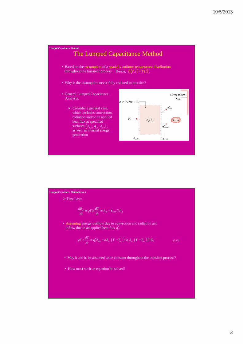
• Based on the assumption of a spatially uniform temperature distributionthroughout the transient process.
• Why is the assumption never fully realized in practice?
• General Lumped Capacitance Analysis:
� Consider a general case, which includes convection,radiation and/or an appliedheat flux at specified surfacesas well as internal energy generation
( ), , ,, , ,s c s r s hA A A
Hence, .( ) ( ),T r t T t≈r
Lumped Capacitance Method (cont.)Lumped Capacitance Method (cont.)
� First Law:
in outst
gdE dT
c E E Edt dt
ρ= ∀ = − +& & &
• Assumingenergy outflow due to convection and radiation andinflow due to an applied heat flux ,sq′′
( ) ( ), , , sur gs s h s c r s r
dTc q A hA T T h A T T E
dtρ ∞′′∀ = − − − − + &
• May h and hr be assumed to be constant throughout the transient process?
• How must such an equation be solved?
(5.15)
10/5/2013
4
Special Case (Negligible Radiation)Special Case (Negligible Radiation)
• Special Cases(Exact Solutions, ) ( )0 iT T≡
� Negligible Radiation ( ), / :T T b aθ θ θ∞ ′≡ − ≡ −
, ,/ /gs c s s ha hA c b q A E cρ ρ ′′≡ ∀ ≡ + ∀
&
The non-homogeneous differential equation is transformed into a homogeneous equation of the form:
da
dt
θ θ′
′= −
Integrating from t = 0 to anyt and rearranging,
( ) ( )/exp 1 exp
i i
T T b aat at
T T T T∞
∞ ∞
− = − + − − − − (5.25)
To what does the foregoing equation reduce as steady state is approached?
How else may the steady-state solution be obtained?
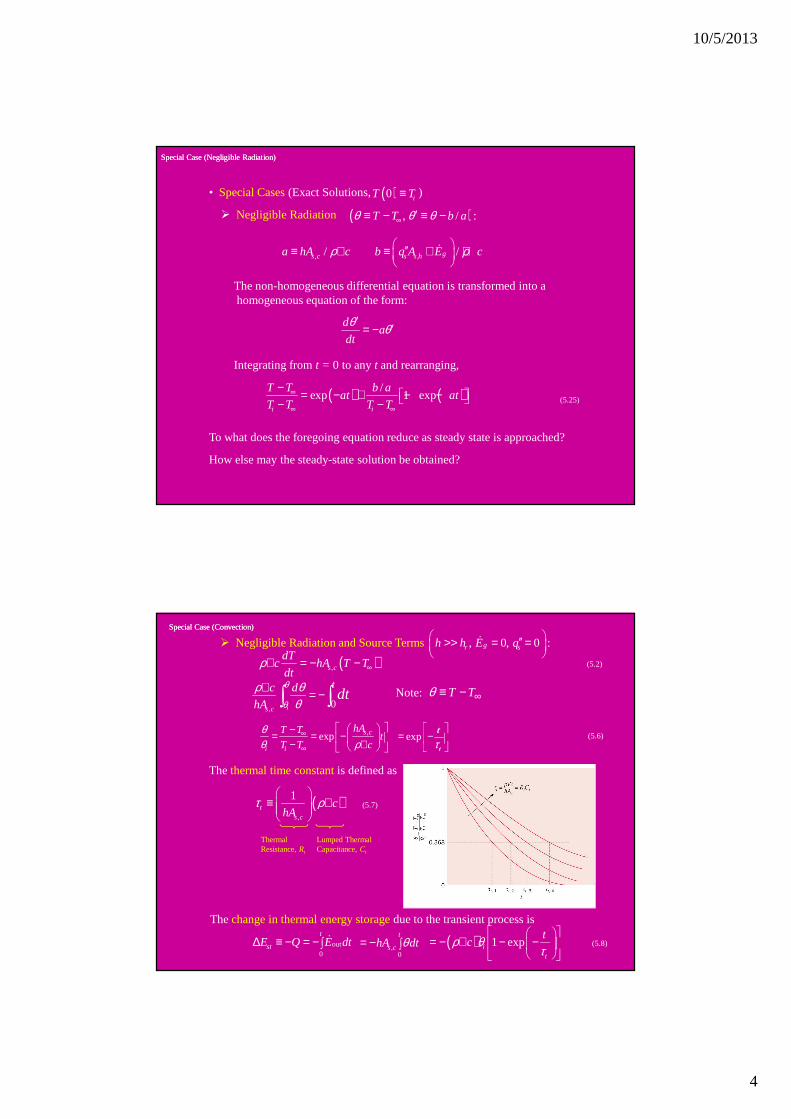
Special Case (Convection)Special Case (Convection)
� Negligible Radiation and Source Terms , 0, 0 :gr sh h E q ′′>> = =
&
( ),s c
dTc hA T T
dtρ ∞∀ = − − (5.2)
, 0is c
tc d
hAdt
θ
θ
ρ θθ
∀ = −∫∫
,exp s c
i i
hAT Tt
T T c
θθ ρ
∞
∞
−= = − − ∀ exp
τ
= − t
t
The thermal time constantis defined as
( ),
1t
s c
chA
τ ρ
≡ ∀
(5.7)
ThermalResistance, Rt
Lumped ThermalCapacitance, Ct
The change in thermal energy storagedue to the transient process is
out0
t
stE Q E dt∆ ≡ − = −∫ & ,0
t
s chA dtθ= − ∫ ( ) 1 expit
tcρ θ
τ
= − ∀ − −
(5.8)
Note: T Tθ ∞≡ −
(5.6)
10/5/2013
5
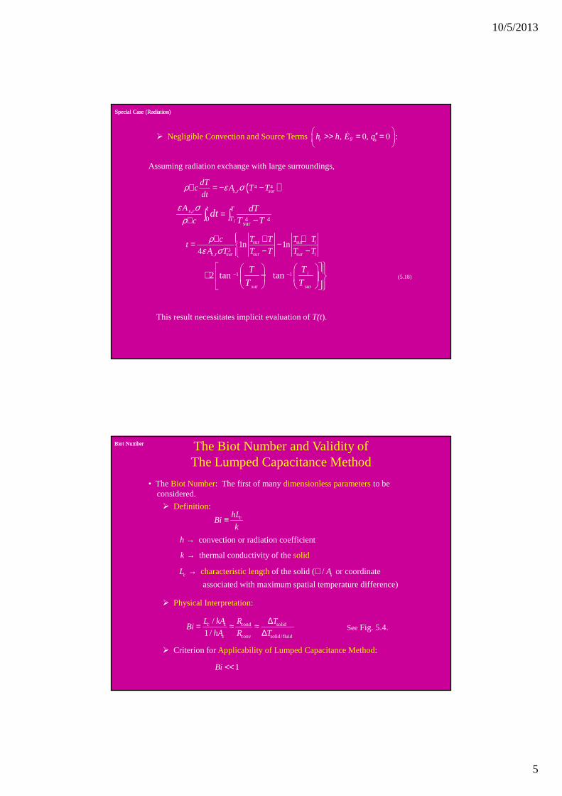
Special Case (Radiation)Special Case (Radiation)
� Negligible Convection and Source Terms , 0, 0 :gr sh h E q ′′>> = =
&
Assuming radiation exchange with large surroundings,
( )4 4, surs r
dTc A T T
dtρ ε σ∀ = − −
,
4 4sur
0 i
s r T
T
tA
c
dTT T
dtε σ
ρ=
∀ −∫∫
sur sur
3, sur sur sur
1n 1n4
i
s r i
T T T Tct
A T T T T T
ρε σ
+ +∀ = − − −
(5.18)
This result necessitates implicit evaluation of T(t).
1 1
sur sur
2 tan tan iTT
T T− −
+ −
Biot NumberBiot Number The Biot Number and Validity ofThe Lumped Capacitance Method
• The Biot Number: The first of many dimensionless parametersto beconsidered.
� Definition:chL
Bik
≡
convection or radiation coefficienth →
thermal conductivity of t so e dh lik →
of the solid ( / or coordinate
associated with maximum spa
char
tial temperature differe
acteristic lengt
e
h
nc )c sL A→ ∀
� Physical Interpretation:
cond solid
conv solid/fluid
/
1 /c s
s
L kA R TBi
hA R T
∆= ≈ ≈∆
� Criterion for Applicability of Lumped Capacitance Method:
1Bi <<
SeeFig. 5.4.

10/5/2013
6
Problem: Thermal Energy StorageProblem: Thermal Energy Storage
Problem 5.12: Charging a thermal energy storage systemconsistingof a packed bedof aluminum spheres.
KNOWN: Diameter, density, specific heat and thermal conductivity of aluminum spheres used in packed bed thermal energy storage system. Convection coefficient and inlet gas temperature.
FIND: Time required for sphere at inlet to acquire 90% of maximum possible thermal energy and the corresponding center temperature.
Schematic:
Problem: Thermal Energy Storage (cont.)Problem: Thermal Energy Storage (cont.)
ASSUMPTIONS: (1) Negligible heat transfer to or from a sphere by radiation or conduction due to contact with other spheres, (2) Constant properties.
Hence, the lumped capacitance approximation may be made, and a uniform temperature may be assumed to exist in the sphere at any time.
( )st 0.90 1 exp / ti
Et
cVτ
ρ θ∆
− = = − −
( )ln 0.1 427 s 2.30 984 stt τ= − = × =
From Eq. (5.6), the corresponding temperature at any location in the sphere is ( ) ( ) ( ), ,984 s exp 6 /g i i g iT T T T ht Dcρ= + − −
( ) ( )( )2 3984 s 300°C 275°C exp 6 75 W/m K 984 s /2700 kg/m 0.075 m 950 J/kg KT = − − × × × × ⋅⋅
If the product of the density and specific heat of copper is (ρc)Cu ≈ 8900 kg/m3 × 400 J/kg⋅K = 3.56 ×
106 J/m
3⋅K, is there any advantage to using copper spheres of equivalent diameter in lieu of aluminum spheres?
Does the time required for a sphere to reach a prescribed state of thermal energy storage change with increasing distance from the bed inlet? If so, how and why?
( )984 s 272.5°CT =
3
2
2700 kg/m 0.075 m 950 J/kg K/ / 6 427 s.
6 75 W/m Kt sVc hA Dc hτ ρ ρ
× × ⋅= = = =
× ⋅
ANALYSIS: To determine whether a lumped capacitance analysis can be used, first compute
Bi = h(ro/3) = 75 W/m2·K (0.0125 m)/150 W/m·K = 0.006 << 1.
From Eq. 5.8, achievement of 90% of the maximum possible thermal energy storage corresponds to
<
<
10/5/2013
7
Problem: Furnace StartProblem: Furnace Start--upup
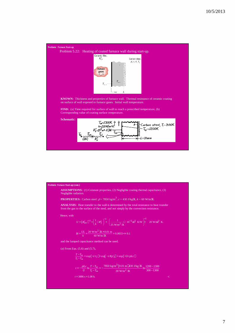
Problem 5.22: Heating of coated furnace wall during start-up.
KNOWN: Thickness and properties of furnace wall. Thermal resistance of ceramic coating on surface of wall exposed to furnace gases. Initial wall temperature.
FIND: (a) Time required for surface of wall to reach a prescribed temperature, (b) Corresponding value of coating surface temperature.
Schematic:
Problem: Furnace StartProblem: Furnace Start--up (cont.)up (cont.)
ASSUMPTIONS: (1) Constant properties, (2) Negligible coating thermal capacitance, (3) Negligible radiation.
PROPERTIES: Carbon steel: ρ = 7850 kg/m3, c = 430 J/kg⋅K, k = 60 W/m⋅K.
ANALYSIS: Heat transfer to the wall is determined by the total resistance to heat transfer from the gas to the surface of the steel, and not simply by the convection resistance.
( )11
1 2 2 2tot 2
1 110 m K/W 20 W/m K.
25 W/m KfU R R
h
−−− − ′′ ′′= = + = + ⋅ = ⋅
⋅
220 W/m K 0.01 m0.0033 0.1
60 W/m K
ULBi
k
⋅ ×= = = <<⋅
and the lumped capacitance method can be used.
(a) From Eqs. (5.6) and (5.7),
( ) ( ) ( )exp / exp / exp /t t ti
T Tt t R C Ut Lc
T Tτ ρ∞
∞
− = − = − = −−
( )3
2
7850 kg/m 0.01 m 430 J/kg K 1200 1300ln ln
300 130020 W/m Ki
T TLct
U T T
ρ ∞∞
⋅− −= − = −− −⋅
3886 s 1.08 h.t = =
Hence, with
<

10/5/2013
8
Problem: Furnace StartProblem: Furnace Start--up (cont.)up (cont.)
(b) Performing an energy balance at the outer surface (s,o),
( ) ( ) /s,o s,o s,i fh T T T T R∞ ′′− = −
( ) ( )
2 -2 2
2
/ 25 W/m K 1300 K 1200 K/10 m K/W
1/ 25 100 W/m K
s,i fs,o
f
hT T RT
h R
∞ ′′+ ⋅ × + ⋅= =′′+ + ⋅
1220 K.s,oT =
How does the coating affect the thermal time constant?
<
Transient Conduction:Transient Conduction:Spatial Effects and the Role ofSpatial Effects and the Role of
Analytical SolutionsAnalytical Solutions
Chapter 5Chapter 5
Sections 5.4 through 5.8Sections 5.4 through 5.8
10/5/2013
9
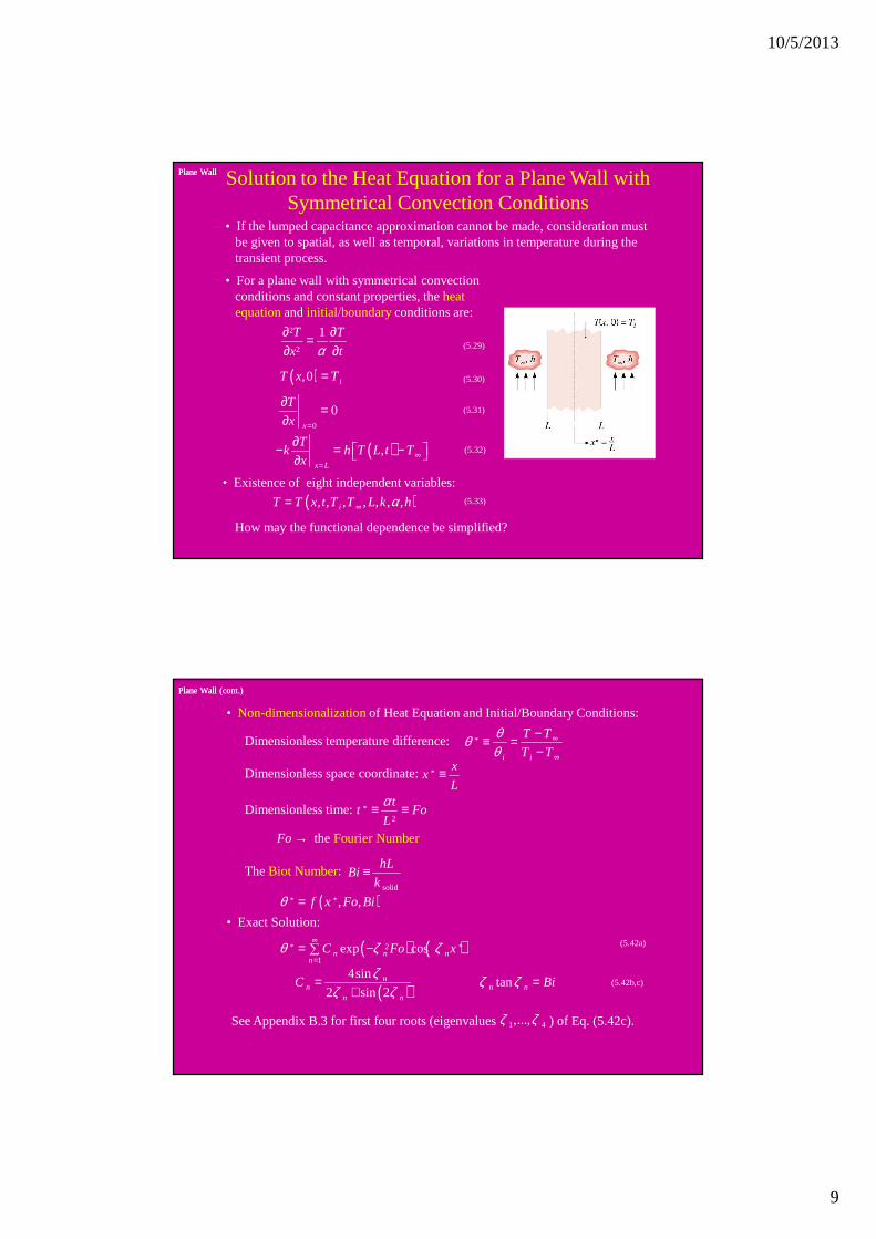
Plane WallPlane Wall Solution to the Heat Equation for a Plane Wall withSymmetrical Convection Conditions
• If the lumped capacitance approximation cannot be made, consideration mustbe given to spatial, as well as temporal, variations in temperature during thetransient process.
• For a plane wall with symmetrical convectionconditions and constant properties, the heatequationand initial/boundary conditions are:
2
2
1T T
x tα∂ ∂=∂ ∂ (5.29)
( ),0 iT x T= (5.30)
0
0x
T
x =
∂ =∂
(5.31)
( ),x L
Tk h T L t T
x ∞=
∂ − = − ∂
(5.32)
• Existence of eight independent variables:
( ), , , , , , ,iT T x t T T L k hα∞= (5.33)
How may the functional dependence be simplified?
Plane Wall (cont.)Plane Wall (cont.)
• Non-dimensionalizationof Heat Equation and Initial/Boundary Conditions:
Dimensionless temperature difference: *
i i
T T
T T
θθθ
∞
∞
−≡ =−
*x
xL
≡Dimensionless space coordinate:
Dimensionless time:*2
tt Fo
L
α≡ ≡
Fourier the Nu mberFo →
The Biot Number:solid
hLBi
k≡
( )* * , ,f x Fo Biθ =• Exact Solution:
( ) ( )* 2 *
1exp cosn n n
nC Fo xθ ζ ζ
∞
== −∑
(5.42a)
( )4sin
tan2 sin 2
nn n n
n n
C Biζ ζ ζ
ζ ζ= =
+(5.42b,c)
See Appendix B.3 for first four roots (eigenvalues ) of Eq. (5.42c).1 4,...,ζ ζ
10/5/2013
10
Plane Wall (cont.)Plane Wall (cont.)
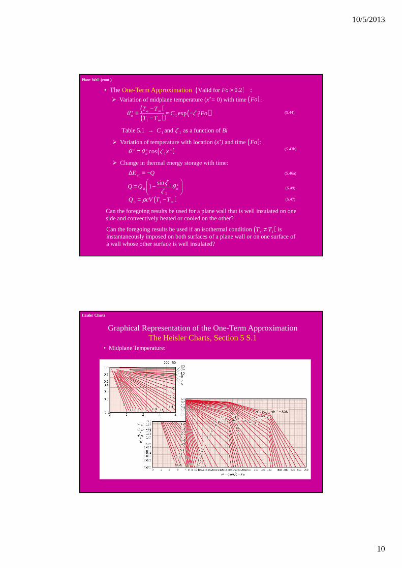
• The One-Term Approximation :( )Valid for 0.2Fo >� Variation of midplane temperature (x*= 0) with time : ( )Fo
( )( ) ( )* 2
1 1expoo
i
T TC Fo
T Tθ ζ∞
∞
−≡ ≈ −
−(5.44)
1 1Table 5.1 and as a function of C Biζ→
� Variation of temperature with location (x*) and time : ( )Fo
( )* * *1coso xθ θ ζ= (5.43b)
� Change in thermal energy storage with time:
stE Q∆ = − (5.46a)
1 *
1
sin1o oQ Q
ζ θζ
= −
(5.49)
( )o iQ cV T Tρ ∞= − (5.47)
Can the foregoing results be used for a plane wall that is well insulated on oneside and convectively heated or cooled on the other?
Can the foregoing results be used if an isothermal condition is instantaneously imposed on both surfaces of a plane wall or on one surface ofa wall whose other surface is well insulated?
( )s iT T≠
Heisler ChartsHeisler Charts
Graphical Representation of the One-Term ApproximationThe Heisler Charts, Section 5 S.1
• Midplane Temperature:

10/5/2013
11
Heisler Charts (cont.)Heisler Charts (cont.)
• Temperature Distribution:
• Change in Thermal Energy Storage:
Radial SystemsRadial Systems
Radial Systems• Long Rods or Spheres Heated or Cooled by Convection.
2
/
/o
o
Bi hr k
Fo t rα==
• One-Term Approximations:Long Rod: Eqs. (5.52) and (5.54)
Sphere: Eqs. (5.53) and (5.55)
1 1, Table 5.1C ζ →
• Graphical Representations:Long Rod: Figs. 5 S.4 – 5 S.6
Sphere: Figs. 5 S.7 – 5 S.9
10/5/2013
12
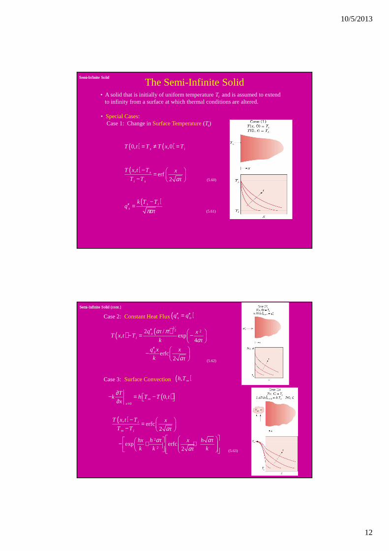
SemiSemi--Infinite SolidInfinite Solid
The Semi-Infinite Solid• A solid that is initially of uniform temperature Ti and is assumed to extend
to infinity from a surface at which thermal conditions are altered.
• Special Cases:Case 1: Change in Surface Temperature(Ts)
( ) ( )0, ,0s iT t T T x T= ≠ =
( ),erf
2s
i s
T x t T x
T T tα− = − (5.60)
( )s is
k T Tq
tπα−
′′ =(5.61)
SemiSemi--Infinite Solid (cont.)Infinite Solid (cont.)
( ) ( ) 12 22 /
, exp4
erfc2
oi
o
q t xT x t T
k t
q x x
k t
α πα
α
′′ − = −
′′ − (5.62)
Case 2:Constant Heat Flux( )s oq q′′ ′′=
( )0
0,x
Tk h T T t
x ∞=
∂ − = − ∂
( )
2
2
,erfc
2
exp erfc2
i
i
T x t T x
T T t
hx h t x h t
k k kt
α
α αα
∞
− = −
− + + (5.63)
Case 3: Surface Convection( ),h T ∞
10/5/2013
13
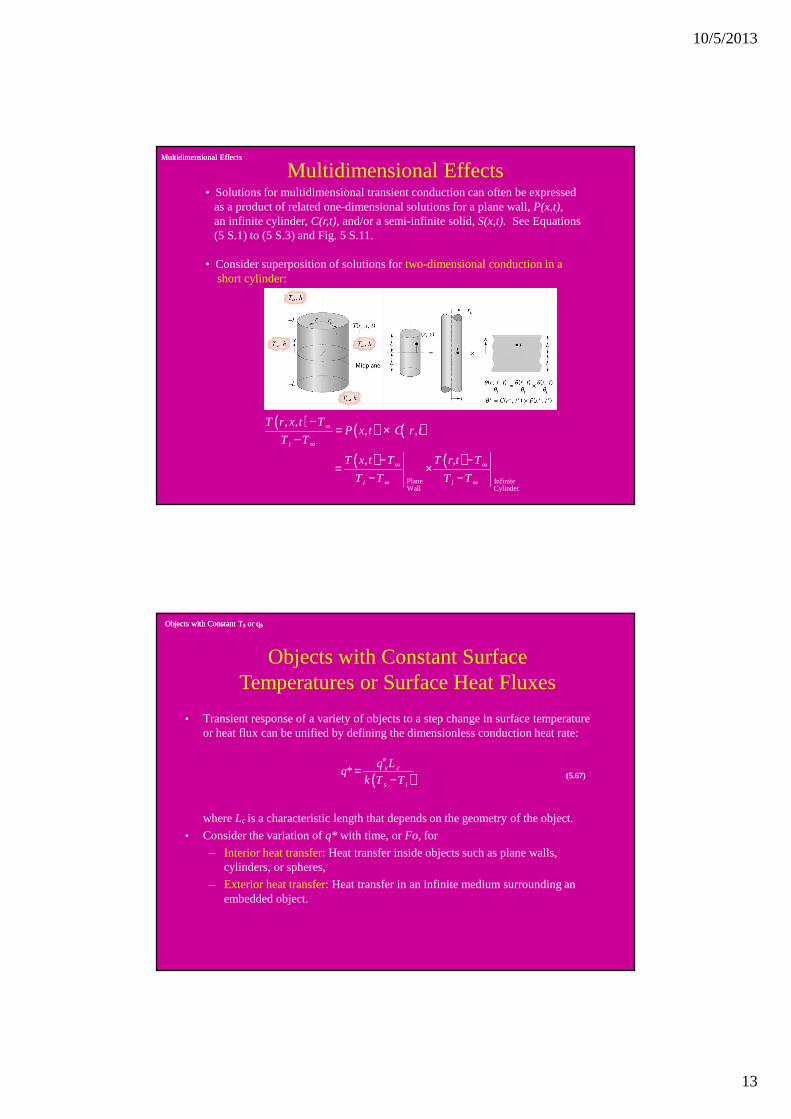
Multidimensional EffectsMultidimensional Effects
Multidimensional Effects• Solutions for multidimensional transient conduction can often be expressed
as a product of related one-dimensional solutions for a plane wall, P(x,t),an infinite cylinder, C(r,t), and/or a semi-infinite solid, S(x,t). See Equations (5 S.1) to (5 S.3) and Fig. 5 S.11.
• Consider superposition of solutions for two-dimensional conduction in ashort cylinder:
( ) ( ) ( )
( ) ( )Plane InfiniteWall Cylinder
, ,, ,
,
i
i i
T r x t TP x t C r t
T T
T x t T T r,t T
T T T T
∞
∞
∞ ∞
∞ ∞
−= ×
−
− −= ×
− −
Objects with Constant TObjects with Constant Tssor qor qss
• Transient response of a variety of objects to a step change in surface temperature or heat flux can be unified by defining the dimensionless conduction heat rate:
Objects with Constant Surface Temperatures or Surface Heat Fluxes
where Lc is a characteristic length that depends on the geometry of the object.
• Consider the variation of q* with time, or Fo, for
– Interior heat transfer: Heat transfer inside objects such as plane walls, cylinders, or spheres,
– Exterior heat transfer: Heat transfer in an infinite medium surrounding an embedded object.
( )* s c
s i
q Lq
k T T
′′=
− (5.67)(5.67)
10/5/2013
14
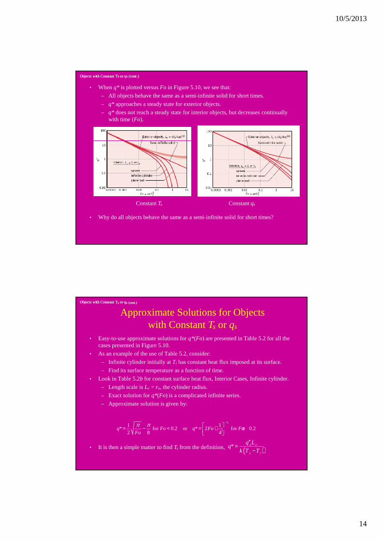
• When q* is plotted versus Fo in Figure 5.10, we see that:
– All objects behave the same as a semi-infinite solid for short times.
– q* approaches a steady state for exterior objects.
– q* does not reach a steady state for interior objects, but decreases continually with time (Fo).
Objects with Constant Ts or Objects with Constant Ts or qsqs (cont.)(cont.)
Constant Ts Constant qs
• Why do all objects behave the same as a semi-infinite solid for short times?
Objects with Constant TObjects with Constant Tssor or qqss (cont.)(cont.)
• Easy-to-use approximate solutions for q*(Fo) are presented in Table 5.2 for all the cases presented in Figure 5.10.
• As an example of the use of Table 5.2, consider:
– Infinite cylinder initially at Ti has constant heat flux imposed at its surface.
– Find its surface temperature as a function of time.
• Look in Table 5.2b for constant surface heat flux, Interior Cases, Infinite cylinder.
– Length scale is Lc = ro, the cylinder radius.
– Exact solution for q*(Fo) is a complicated infinite series.
– Approximate solution is given by:
Approximate Solutions for Objects with Constant Ts or qs
• It is then a simple matter to find Ts from the definition,
11 1
* for 0.2 or * 2 for 0.22 8 4
q Fo q Fo FoFo
π π − = − < = + ≥
( )* s c
s i
q Lq
k T T
′′=
−
10/5/2013
15
Problem: Thermal Energy StorageProblem: Thermal Energy Storage
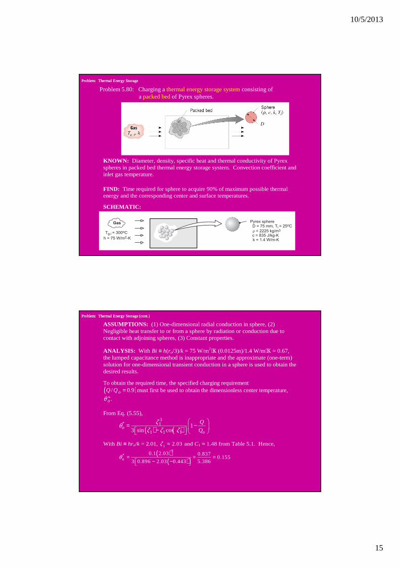
Problem 5.80: Charging a thermal energy storage systemconsisting ofa packed bedof Pyrex spheres.
KNOWN: Diameter, density, specific heat and thermal conductivity of Pyrex spheres in packed bed thermal energy storage system. Convection coefficient and inlet gas temperature.
FIND: Time required for sphere to acquire 90% of maximum possible thermal energy and the corresponding center and surface temperatures.
SCHEMATIC:
Problem: Thermal Energy Storage (cont.)Problem: Thermal Energy Storage (cont.)
ASSUMPTIONS: (1) One-dimensional radial conduction in sphere, (2) Negligible heat transfer to or from a sphere by radiation or conduction due to contact with adjoining spheres, (3) Constant properties.
ANALYSIS: With Bi ≡ h(ro/3)/k = 75 W/m2⋅K (0.0125m)/1.4 W/m⋅K = 0.67, the lumped capacitance method is inappropriate and the approximate (one-term) solution for one-dimensional transient conduction in a sphere is used to obtain the desired results.
To obtain the required time, the specified charging requirement ( )/ 0.9oQ Q = must first be used to obtain the dimensionless center temperature,
* .oθ
From Eq. (5.55),
( ) ( )31
1 1 11
3 sin cosoo
Q
Q
ζθζ ζ ζ
∗ = − −
With Bi ≡ hro/k = 2.01, 1 2.03ζ ≈ and C1 ≈ 1.48 from Table 5.1. Hence,
( )
( )
3
o0.1 2.03 0.837
0.1555.3863 0.896 2.03 0.443
θ ∗ = = =− −
10/5/2013
16
Problem: Thermal Energy Storage (cont.)Problem: Thermal Energy Storage (cont.)
From Eq. (5.53c), the corresponding time is
2
211
lno ort
C
θαζ
∗ = −
( )3 7 2/ 1.4 W/m K / 2225kg/m 835J/kg K 7.54 10 m /s,k cα ρ −= = ⋅ × ⋅ = ×
( ) ( )
( )
2
27 2
0.0375 ln 0.155 /1.481,020 s
7.54 10 m /s 2.03
mt
−= − =
×
From the definition of * ,oθ the center temperature is ( ), ,0.155 300°C 42.7°C 257.3°Co g i i g iT T T T= + − = − =
The surface temperature at the time of interest may be obtained from Eq. (5.53b)
with 1,r∗ =
( ) ( )1, ,
1
sin 0.155 0.896300°C 275°C 280.9°C
2.03o
s g i i g iT T T Tθ ζ
ζ
∗ × = + − = − =
Is use of the one-term approximation appropriate?
<
<
<
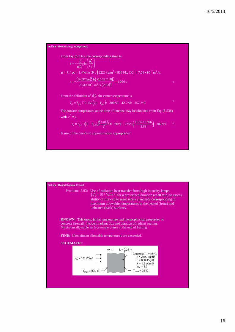
Problem: Thermal Response FirewallProblem: Thermal Response Firewall
Problem: 5.93: Use of radiation heat transfer from high intensity lampsfor a prescribed duration (t=30 min) to assess
ability of firewall to meet safety standards corresponding tomaximum allowable temperatures at the heated (front) andunheated (back) surfaces.
( )4 210 W/msq′′ =
KNOWN: Thickness, initial temperature and thermophysical properties of concrete firewall. Incident radiant flux and duration of radiant heating. Maximum allowable surface temperatures at the end of heating.
FIND: If maximum allowable temperatures are exceeded.
SCHEMATIC:
10/5/2013
17
Problem: Thermal Response of Firewall (cont.)Problem: Thermal Response of Firewall (cont.)
ASSUMPTIONS: (1) One-dimensional conduction in wall, (2) Validity of semi-infinite medium approximation, (3) Negligible convection and radiative exchange with the surroundings at the irradiated surface, (4) Negligible heat transfer from the back surface, (5) Constant properties.
ANALYSIS: The thermal response of the wall is described by Eq. (5.62)
( ) ( )1/2 22 /, exp erfc
4 2o o
iq t q xx x
T x t Tk t k t
α πα α
′′ ′′− = + −
where, 7 2/ 6.92 10 m /spk cα ρ −= = × and for
( )1/230 min 1800 s, 2 / / 284.5 K.ot q t kα π′′= = = Hence, at x = 0,
( )0,30 min 25°C 284.5°C 309.5°C 325°CT = + = <At
( ) ( )1/ 220.25 m, / 4 12.54; / 1,786 K, and / 2 3.54.ox x t q x k x tα α′′= − = − = =
Hence, ( ) ( ) ( )60.25 m, 30 min 25 284.5°C 3.58 10 1786°C ~ 0 25°CT C −= ° + × − × ≈
Problem: Thermal Response of Firewall (cont.)Problem: Thermal Response of Firewall (cont.)
Both requirements are met.
Is the assumption of a semi-infinite solid for a plane wall of finite thickness appropriate under the foregoing conditions?
COMMENTS: The foregoing analysis may or may not be conservative, since heat transfer at the irradiated surface due to convection and net radiation exchange with the environment has been neglected. If the emissivity of the surface and the temperature of the surroundings are assumed to be ε = 1 and Tsur = 298K, radiation exchange at Ts = 309.5°C would be
( )4 4 2rad sur 6080 W/m K,sq T Tεσ′′ = − = ⋅
which is significant (~ 60% of the prescribed radiation). However, under actual conditions, the wall would likely be exposed to combustion gases and adjoining walls at elevated temperatures.
<
10/5/2013
18
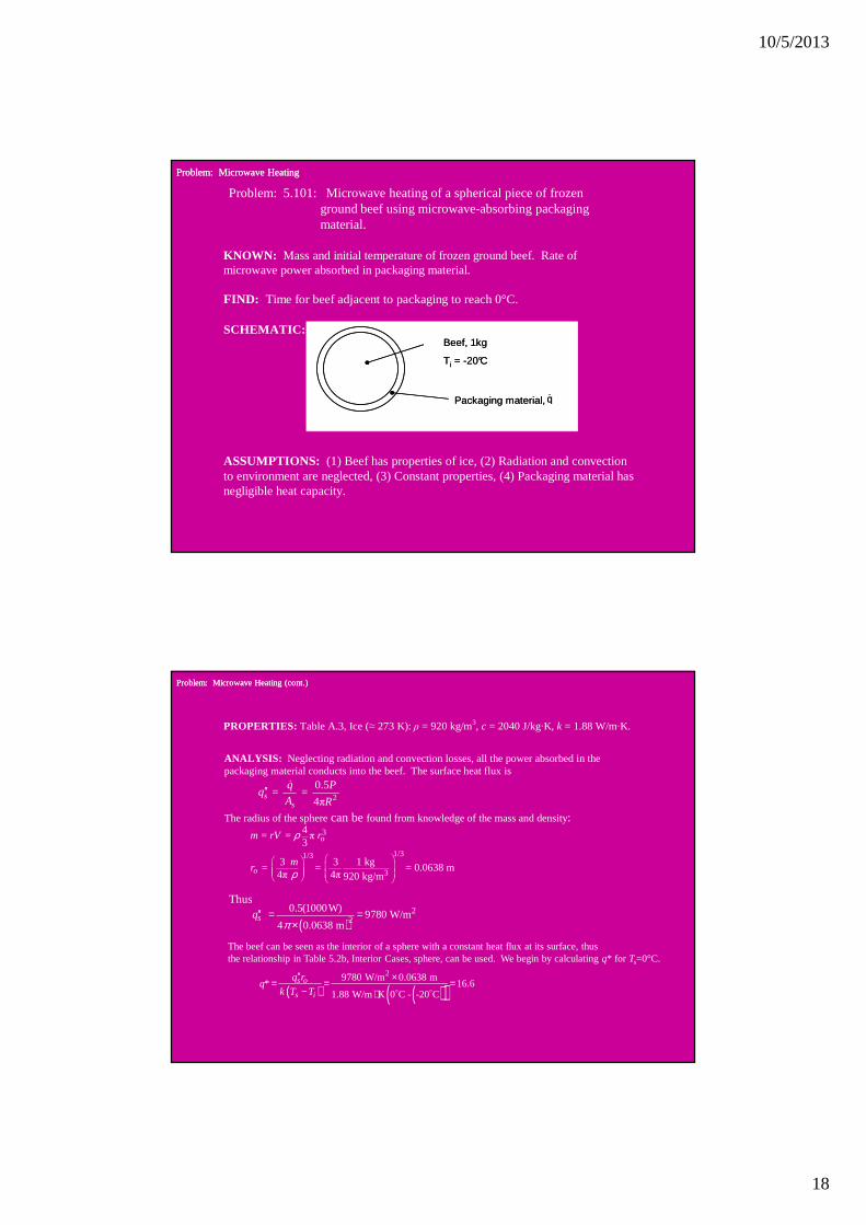
Problem: Microwave HeatingProblem: Microwave Heating
Problem: 5.101: Microwave heating of a spherical piece of frozen ground beef using microwave-absorbing packaging material.
KNOWN: Mass and initial temperature of frozen ground beef. Rate of microwave power absorbed in packaging material.
FIND: Time for beef adjacent to packaging to reach 0°C.
SCHEMATIC: Beef, 1kg
Ti = -20°C
Packaging material, &q
Beef, 1kg
Ti = -20°C
Packaging material, &q
ASSUMPTIONS: (1) Beef has properties of ice, (2) Radiation and convection to environment are neglected, (3) Constant properties, (4) Packaging material has negligible heat capacity.
Problem: Microwave Heating (cont.)Problem: Microwave Heating (cont.)
PROPERTIES: Table A.3, Ice (≈ 273 K): ρ = 920 kg/m3, c = 2040 J/kg·K, k = 1.88 W/m·K.
ANALYSIS: Neglecting radiation and convection losses, all the power absorbed in the packaging material conducts into the beef. The surface heat flux is
2
0.5 = =
4πs
s
q Pq
A R′′ &
The radius of the sphere can be found from knowledge of the mass and density: 3
1/31/3
3
4 = = π 3
1 kg3 3 = = = 0.0638 m4π 4π 920 kg/m
o
o
m rV r
mr
ρ
ρ
Thus
( )2
20.5(1000W)
9780 W/m4 0.0638 m
sqπ
′′ = =×
( ) ( )( )29780 W/m 0.0638 m
* 16.61.88 W/m K 0 C - -20 C
s o
s i
q rq
k T T
′′ ×= = =− ⋅ o o
The beef can be seen as the interior of a sphere with a constant heat flux at its surface, thus the relationship in Table 5.2b, Interior Cases, sphere, can be used. We begin by calculating q* for Ts=0°C.

10/5/2013
19
Problem: Microwave Heating (cont.)Problem: Microwave Heating (cont.)
We proceed to solve for Fo. Assuming that Fo < 0.2, we have
1 π π* -
2 4q
Fo≅
-2π
= π 2( * + ) = 0.00264
Fo q
Since this is less than 0.2, our assumption was correct. Finally we can solve for the time:
2 2
2 3
= / =
= (0.0026 × (0.0638 m) × 920 kg/m × 2040 J/kg K)/(1.88 W/m K) o ot Fo r Fo r c / kα ρ
⋅ ⋅
COMMENTS: At the minimum surface temperature of -20°C, with T∞
= 30°C and h = 15 W/m2·K from Problem 5.33, the convection heat flux is 750 W/m2, which is less than 8% of the microwave heat flux. The radiation heat flux would likely be less, depending on the temperature of the oven walls.
= 10.6 s <