
TRANSIENT THERMAL ANALYSIS OF SMALL … SJ_201505.pdf · simulation, computational fluid dynamics,...
4
560 | 2015 | MARCH | SCIENCE JOURNAL 1. INTRODUCTION All electrical machines generate losses in form of heat generation. Obviously, this quantity of heat must be cleared away to prevent damage of the machine. Furthermore, machine rating mainly depend on the thermal capability of the system. A lots of industry application problems of IMs relate to the thermal limitations of machine. Nowadays, the squirrel cage induction motor is most common used as industrial drives. Main benefits of IM is simple design and construction. Further IM is characterized reliable operation, low initial cost, easy operation and maintenance, relatively high efficiency, etc. Because IM has very important position in industry therefore thermal analysis is required at designing process of new IM. The maximizing use of electrical machines leads to an increase in electrical load of active components. Losses that arise in these parts, have resulted in increasing the temperature of active components, or the whole machine. This issue is important to address simultaneously the electromagnetic and mechanical design of IM. A magnetic circuit has similar, sort of limitations needed to be also took into account in machine design. From the above it is clear that identifying of the temperature of all critical parts is of key importance. Because this type of electric machines has very important position in industry and has very significant advantages, numerous studies were presented in the field of thermal analysis of IM. [Alberti 2008], [Zhang 2012], [Trigeol 2006]. 2. CALCULATION METHODS 2.1 Losses of Induction Motor At thermal analysis of IM is necessary to know the values of the losses and their exact location in the motor. The calculation of losses is based on known dimensions and electrical parameters of IM. These TRANSIENT THERMAL ANALYSIS OF SMALL SQUIRREL CAGE MOTOR THROUGH COUPLED FEA ROMAN PECHANEK 1 , VLADIMIR KINDL 1 , BOHUMIL SKALA 2 1 Faculty of Electrical Engineering Regional Innovation Centre for Electrical Engineering University of West Bohemia, Pilsen, Czech Republic 2 Faculty of Electrical Engineering University of West Bohemia, Pilsen, Czech Republic e-mail: [email protected] KEYWORDS induction motors, machine modelling, thermal analysis, simulation, computational fluid dynamics, finite element analysis, The thermal analysis is necessary in design process of new electric motor. During motor design process is necessary to know temperatures of induction motor’s (IM’s) construction parts. The calculated temperatures in all motor parts should be lower than critical temperatures. This paper deals with free-dimensional (3D) transient thermal analysis of small squirrel cage motor/induction motor. The design of new IM is based on dimensions of permanent magnet synchronous motor (PMSM). In the initial stage of motor's design the coupled finite element analysis (FEA) method gives enough valuable results of the IM's temperature rise. Coupled thermal analysis is made through computational fluid dynamics (CFD) and finite element method (FEM). The CFD model of IM is used for calculate boundary condition such as heat transfer coefficient. Results of CFD model are implemented in to transient thermal analysis as boundary condition. parameters are known from design stage. According this fact IM’s losses are set by analytical method. All formulas for calculating losses are presented. IM’s losses can be divided to I 2 R losses, iron core losses, additional losses and mechanical losses. The losses in magnetic circuit can be further divided into: eddy current and hysteresis losses, surface losses and the losses due to flux pulsation. [Kindl 2010] In simulation mechanical losses are neglected. Based on empirical relationships can be established only total mechanical losses. However there is a problem with their specific location and dividing in machine. They are therefore neglected. I 2 R losses in the stator and rotor windings are described by: (1) where m is number of phases, R 1,2 is stator/rotor winding resistance, I is supply current. Iron core losses are determined based on the relationship (2) where ∆p 1,0 is specific losses of used iron, f is supply frequency, β coefficient dependent on used lamination, k dj is coefficient representing inhomogeneous flux density distribution, B j is average flux density in division of magnetic circuit, m j is weight of division of magnetic circuit. Additional losses are considered as no-load losses incurred in: Surface of iron core in air gap (3) where D 1 is stator inner diameter, α is pole coverage coefficient, l e is length of stator/rotor packet, k 0 is factor of surface loss, Q 1,2 is number of slots, n is RPM, t d1 is slot pitch, β δ is pulsation in the air gap flux density. For the stator teeth the β 0x depends on the ratio of slots opening and the air gap length. Similarly are set teeth losses due to pulsating magnetic flux (4) where Q 1,2 is number of slots, n is RPM, m j1,2 is weight of stator/rotor teeth, B p1,2 is magnitude of flux density saturating stator/rotor teeth. 2.2 Fluid Dynamics Model The fluid flow calculation is the first indicator of the cooling capability of the electrical machine. The modeling of fluid flow generally are presented two basic approaches. Modelling through a lumped parameter method and through CFD methods. In presented paper is CFD method used. Simulation of coupled analysis is performed in software ANSYS. Due to this method is possible to simulate fluid flow by numerical solution of the Navier-Stokes equations. In principle, the Navier-Stokes equations describe both laminar and turbulent flows without the need for additional information. The turbulent flow is more often during a cooling process of electrical machine. [Kolondzovski 2010], [Kuosa 2004], [Marignetti 2008]. Navier-Stokes equation and continuity equation for an incompressible fluid (5) (5) where ρ is density, U is speed, ∇ is Laplace operator, p is pressure, η is dynamic viscosity and f is volume force acting on the fluid. Solving this equation is problematic because of the nonlinear inertia term which generates turbulence. Turbulence consists of fluctuations in the flow field in time and space. It is a complex process, mainly because it is three dimensional, unsteady and consists of many scales. It can have a significant effect on the characteristics of the flow. Turbulence occurs when the inertia forces in the fluid become significant compared
Transcript of TRANSIENT THERMAL ANALYSIS OF SMALL … SJ_201505.pdf · simulation, computational fluid dynamics,...

560 | 2015 | MARCH | SCIENCE JOURNAL| | | | | | | | | | | | | 2015 | MARCH | SCIENCE JOURNAL | 561
1. INTRODUCTIONAll electrical machines generate losses in form of heat generation. Obviously, this quantity of heat must be cleared away to prevent damage of the machine. Furthermore, machine rating mainly depend on the thermal capability of the system. A lots of industry application problems of IMs relate to the thermal limitations of machine.
Nowadays, the squirrel cage induction motor is most common used as industrial drives. Main benefits of IM is simple design and construction. Further IM is characterized reliable operation, low initial cost, easy operation and maintenance, relatively high efficiency, etc. Because IM has very important position in industry therefore thermal analysis is required at designing process of new IM.
The maximizing use of electrical machines leads to an increase in electrical load of active components. Losses that arise in these parts, have resulted in increasing the temperature of active components, or the whole machine. This issue is important to address simultaneously the electromagnetic and mechanical design of IM. A magnetic circuit has similar, sort of limitations needed to be also took into account in machine design. From the above it is clear that identifying of the temperature of all critical parts is of key importance.
Because this type of electric machines has very important position in industry and has very significant advantages, numerous studies were presented in the field of thermal analysis of IM. [Alberti 2008], [Zhang 2012], [Trigeol 2006].
2. CALCULATION METHODS 2.1 Losses of Induction MotorAt thermal analysis of IM is necessary to know the values of the losses and their exact location in the motor. The calculation of losses is based on known dimensions and electrical parameters of IM. These
TRANSIENT THERMAL ANALYSIS OF SMALL
SQUIRREL CAGE MOTOR THROUGH COUPLED FEA
ROMAN PECHANEK1, VLADIMIR KINDL1, BOHUMIL SKALA2
1Faculty of Electrical EngineeringRegional Innovation Centre for Electrical Engineering
University of West Bohemia, Pilsen, Czech Republic2Faculty of Electrical Engineering
University of West Bohemia, Pilsen, Czech Republic
e-mail: [email protected]
KEYWORDSinduction motors, machine modelling, thermal analysis,
simulation, computational fluid dynamics, finite element analysis,
The thermal analysis is necessary in design process of new electric motor. During motor design process is necessary to know temperatures of induction motor’s (IM’s) construction parts. The calculated temperatures in all motor parts should be lower than critical temperatures. This paper deals with free-dimensional (3D) transient thermal analysis of small squirrel cage motor/induction motor. The design of new IM is based on dimensions of permanent magnet synchronous motor (PMSM). In the initial stage of motor's design the coupled finite element analysis (FEA) method gives enough valuable results of the IM's temperature rise. Coupled thermal analysis is made through computational fluid dynamics (CFD) and finite element method (FEM). The CFD model of IM is used for calculate boundary condition such as heat transfer coefficient. Results of CFD model are implemented in to transient thermal analysis
as boundary condition.
parameters are known from design stage. According this fact IM’s losses are set by analytical method. All formulas for calculating losses are presented. IM’s losses can be divided to I2R losses, iron core losses, additional losses and mechanical losses. The losses in magnetic circuit can be further divided into: eddy current and hysteresis losses, surface losses and the losses due to flux pulsation. [Kindl 2010] In simulation mechanical losses are neglected. Based on empirical relationships can be established only total mechanical losses. However there is a problem with their specific location and dividing in machine. They are therefore neglected. I2R losses in the stator and rotor windings are described by:
(1)
where m is number of phases, R1,2 is stator/rotor winding resistance, I is supply current. Iron core losses are determined based on the relationship
(2)
where ∆p1,0 is specific losses of used iron, f is supply frequency, β coefficient dependent on used lamination, kdj is coefficient representing inhomogeneous flux density distribution, Bj is average flux density in division of magnetic circuit, mj is weight of division of magnetic circuit.
Additional losses are considered as no-load losses incurred in: Surface of iron core in air gap
(3)
where D1 is stator inner diameter, α is pole coverage coefficient, le is length of stator/rotor packet, k0 is factor of surface loss, Q1,2 is number of slots, n is RPM, td1 is slot pitch, βδ is pulsation in the air gap flux density. For the stator teeth the β0x depends on the ratio of slots opening and the air gap length. Similarly are set teeth losses due to pulsating magnetic flux
(4)
where Q1,2 is number of slots, n is RPM, mj1,2 is weight of stator/rotor teeth, Bp1,2 is magnitude of flux density saturating stator/rotor teeth.
2.2 Fluid Dynamics ModelThe fluid flow calculation is the first indicator of the cooling capability of the electrical machine. The modeling of fluid flow generally are presented two basic approaches. Modelling through a lumped parameter method and through CFD methods. In presented paper is CFD method used. Simulation of coupled analysis is performed in software ANSYS. Due to this method is possible to simulate fluid flow by numerical solution of the Navier-Stokes equations. In principle, the Navier-Stokes equations describe both laminar and turbulent flows without the need for additional information. The turbulent flow is more often during a cooling process of electrical machine. [Kolondzovski 2010], [Kuosa 2004], [Marignetti 2008]. Navier-Stokes equation and continuity equation for an incompressible fluid (5)
(5)
where ρ is density, U is speed, ∇ is Laplace operator, p is pressure, η is dynamic viscosity and f is volume force acting on the fluid.
Solving this equation is problematic because of the nonlinear inertia term which generates turbulence. Turbulence consists of fluctuations in the flow field in time and space. It is a complex process, mainly because it is three dimensional, unsteady and consists of many scales. It can have a significant effect on the characteristics of the flow. Turbulence occurs when the inertia forces in the fluid become significant compared
560 | 2015 | MARCH | SCIENCE JOURNAL 2015 | MARCH | SCIENCE JOURNAL | 561 | | | | | | | | | | | | |
rated power, rated current, rated voltage, rated speed and efficiency of IM. The value of efficiency consider all types of losses in IM from design stage.
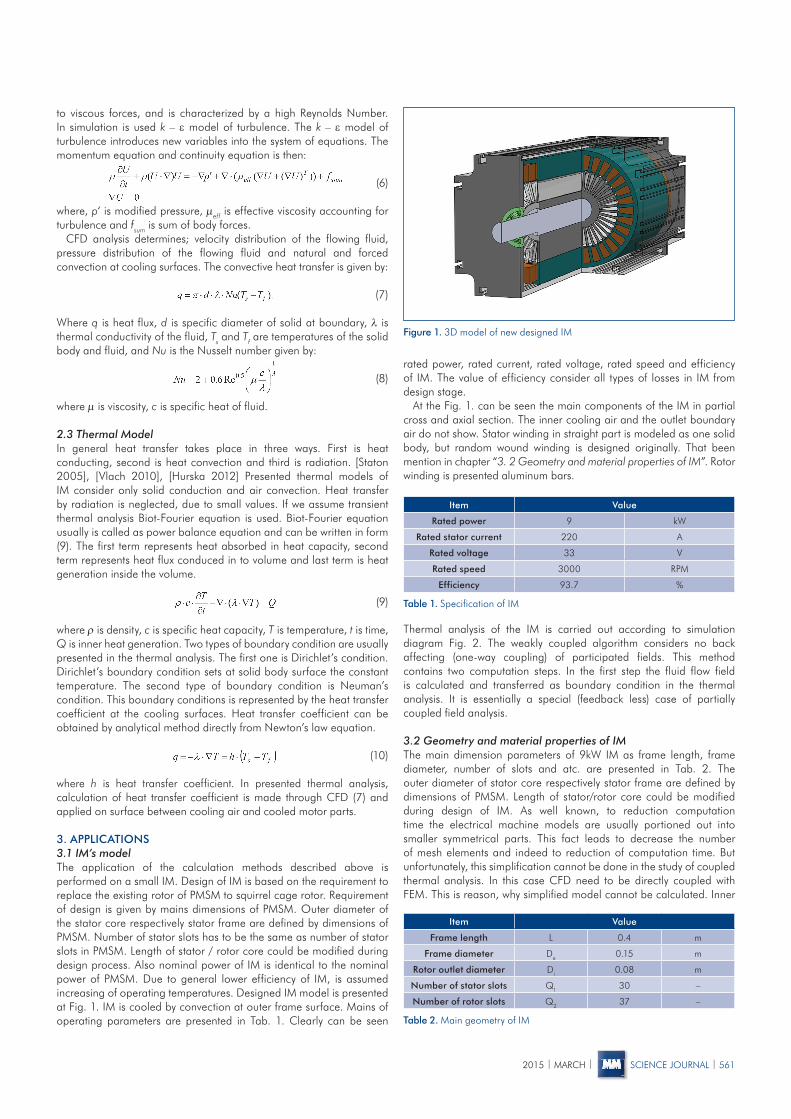
At the Fig. 1. can be seen the main components of the IM in partial cross and axial section. The inner cooling air and the outlet boundary air do not show. Stator winding in straight part is modeled as one solid body, but random wound winding is designed originally. That been mention in chapter “3. 2 Geometry and material properties of IM”. Rotor winding is presented aluminum bars.
Thermal analysis of the IM is carried out according to simulation diagram Fig. 2. The weakly coupled algorithm considers no back affecting (one-way coupling) of participated fields. This method contains two computation steps. In the first step the fluid flow field is calculated and transferred as boundary condition in the thermal analysis. It is essentially a special (feedback less) case of partially coupled field analysis.
3.2 Geometry and material properties of IMThe main dimension parameters of 9kW IM as frame length, frame diameter, number of slots and atc. are presented in Tab. 2. The outer diameter of stator core respectively stator frame are defined by dimensions of PMSM. Length of stator/rotor core could be modified during design of IM. As well known, to reduction computation time the electrical machine models are usually portioned out into smaller symmetrical parts. This fact leads to decrease the number of mesh elements and indeed to reduction of computation time. But unfortunately, this simplification cannot be done in the study of coupled thermal analysis. In this case CFD need to be directly coupled with FEM. This is reason, why simplified model cannot be calculated. Inner
Figure 1. 3D model of new designed IM
to viscous forces, and is characterized by a high Reynolds Number. In simulation is used k – ε model of turbulence. The k – ε model of turbulence introduces new variables into the system of equations. The momentum equation and continuity equation is then:
(6)
where, p‘ is modified pressure, µeff is effective viscosity accounting for turbulence and fsum is sum of body forces.
CFD analysis determines; velocity distribution of the flowing fluid, pressure distribution of the flowing fluid and natural and forced convection at cooling surfaces. The convective heat transfer is given by:
(7)
Where q is heat flux, d is specific diameter of solid at boundary, λ is thermal conductivity of the fluid, Ts and Tf are temperatures of the solid body and fluid, and Nu is the Nusselt number given by:
(8)
where µ is viscosity, c is specific heat of fluid.
2.3 Thermal ModelIn general heat transfer takes place in three ways. First is heat conducting, second is heat convection and third is radiation. [Staton 2005], [Vlach 2010], [Hurska 2012] Presented thermal models of IM consider only solid conduction and air convection. Heat transfer by radiation is neglected, due to small values. If we assume transient thermal analysis Biot-Fourier equation is used. Biot-Fourier equation usually is called as power balance equation and can be written in form (9). The first term represents heat absorbed in heat capacity, second term represents heat flux conduced in to volume and last term is heat generation inside the volume.
(9)
where ρ is density, c is specific heat capacity, T is temperature, t is time, Q is inner heat generation. Two types of boundary condition are usually presented in the thermal analysis. The first one is Dirichlet’s condition. Dirichlet’s boundary condition sets at solid body surface the constant temperature. The second type of boundary condition is Neuman’s condition. This boundary conditions is represented by the heat transfer coefficient at the cooling surfaces. Heat transfer coefficient can be obtained by analytical method directly from Newton’s law equation.
(10)
where h is heat transfer coefficient. In presented thermal analysis, calculation of heat transfer coefficient is made through CFD (7) and applied on surface between cooling air and cooled motor parts.
3. APPLICATIONS3.1 IM’s modelThe application of the calculation methods described above is performed on a small IM. Design of IM is based on the requirement to replace the existing rotor of PMSM to squirrel cage rotor. Requirement of design is given by mains dimensions of PMSM. Outer diameter of the stator core respectively stator frame are defined by dimensions of PMSM. Number of stator slots has to be the same as number of stator slots in PMSM. Length of stator / rotor core could be modified during design process. Also nominal power of IM is identical to the nominal power of PMSM. Due to general lower efficiency of IM, is assumed increasing of operating temperatures. Designed IM model is presented at Fig. 1. IM is cooled by convection at outer frame surface. Mains of operating parameters are presented in Tab. 1. Clearly can be seen
Item Value
Rated power 9 kW
Rated stator current 220 A
Rated voltage 33 V
Rated speed 3000 RPM
Efficiency 93.7 %
Item Value
Frame length L 0.4 m
Frame diameter De 0.15 m
Rotor outlet diameter Di 0.08 m
Number of stator slots Q1 30 –
Number of rotor slots Q2 37 –
Table 1. Specification of IM
Table 2. Main geometry of IM

562 | 2015 | MARCH | SCIENCE JOURNAL| | | | | | | | | | | | | 2015 | MARCH | SCIENCE JOURNAL | 563
cooling air is modeled separately as auxiliary part of motor solid body. Outer air is modeled as ambient enclosure.
Thermal parameters of machine parts are presented in Tab. 3. The computational model is in 3D. This fact allows to set different material properties in different directions. One of the most important parameter is thermal conductivity of stator winding. At original stator winding comprises of insulated wire. Insulated wire is placed in insulated slots. In 3D mathematical model is winding simplified into one volume. That means equivalent thermal conductivity of stator winding have to be defined. The equivalent thermal conductivity of windings is set by relation
(11)
where λw is equivalent thermal conductivity of winding, δ is length of windings parts.
3.3 Loads and Boundary ConditionsIn the case of thermal analysis, loads are presented by I2R losses in motor windings and losses in magnetic circuit. All thermal loads are calculated according analytical methods described in chapter 2.1. Thermal load are presented in Tab. 4.
Mechanical losses are neglected since their determination is uncertain in the calculation. Furthermore, it is not sufficient accuracy found a parts of the machine, where mechanical losses arises. Neglect of mechanical losses in simulation is seen as a zero heat source in the bearings. This concept is not correct with the physical theory. But in the case that more important is the calculation of the stator winding temperature, can be mechanical losses neglected. The value of mechanical losses in the design stage was set to 98W.
Boundary condition of thermal analysis are calculated through CDF and implement at cooling surface of machine. This fact leads to reduce calculating time. Initial temperature of transient thermal analysis is Tamb = 0°C.
In the case of CFD simulation. Two calculations are presented first is inner air, second is outer cooling air. The model of inner air of the motor represents convection heat transfer from rotor parts to IM frame, and heat
transfer through air gap of IM. Model of outer cooling air describes heat convection to ambient air. Boundary conditions of inner air CFD model are walls with equivalent friction f = 0.01 mm and with heat transfer. Inner calculation model in addition include rotating parts. Prerequisite are set rotating wall as boundary condition. Outer cooling air volume, the boundary conditions are set as wall with equivalent friction f = 0.01 mm and with heat transfer at border of machine frame and cooling air. Also “Opening” boundary condition is used at outer faces of air volume. “Relative Pressure” is set to 1 Pa and “Opening Temperature” is set to 0 °C. Presented process corresponds with solving diagram at Fig. 2.
4. RESULTSAt this place transient thermal analysis results of small IM are presented. Results are presented for nominal load 9 kW and nominal speed of machine 3000 RPM. We assume that all thermal heating move from motor by frame surface. Due to this fact two types of simulation results are presented at this chapter. First results from CFD analysis. That results are presented by heat transfer coefficient on frame of IM see Fig. 3. This result are directly coupled to transient thermal analysis.
Heat transfer coefficient at outer surface of IM frame are in range h = 13 – 17 Wm2/K. Heat transfer coefficient at inner surface depends on rotating speed respectively at air flow speed. At rotating surface heat transfer coefficient are in range h = 60 – 120 Wm2/K. The heat transfer coefficient at stationary surface reach lower values h = 45 – 70 Wm2/K.
MaterialThermal
conductivity[W/mK]
Specific heat[J/kgK]
Density[kg/m3]
Stator winding kx = 2ky = 4
kz = 380390 8900
Stator core kx = 40ky = 40kz = 2
460 7900
Rotor squirel cage 160 870 2270
Rotor core kx=40ky=40kz=2
460 7900-
Frame 160 870 2270
Air 0.03 1000 1.3
Table 3. Material data of IM
Item Value
Rotor speed 3 000 RPM
I2R stator losses 143.20 W
Iron core losses 100.63 W
I2R rotor losses 125.97 W
Addy losses 135.35 W
Table 4. Thermal loads of IM
Figure 2. Simulation diagram
Figure 3. Heat transfer coefficient
Second presented types of results are transient thermal analysis results. Simulation was starting from cold (ambient) temperature Tamb = 0°C. The simulation of temperature rise takes 1 hour. After this time the operating temperature of IM stabilizes. The time step are set to 60 seconds. IM at cross and axial section is presented at Fig. 4.Fig. 4. shows IM place with the lowest and highest final temperatures. Locations with the lowest steady-state temperature is bearing, bearing shields and motor frame. The steady-state temperature of bearing shields are 124 °C. The highest final temperature of stator frame is 132 °C.
The final temperature distributions at the stator geometry is presented in Fig. 5. Figure shows the difference in temperature of the stator

562 | 2015 | MARCH | SCIENCE JOURNAL 2015 | MARCH | SCIENCE JOURNAL | 563 | | | | | | | | | | | | |
Figure 4. Temperatures distribution
straight winding parts and the overhang winding parts. Minimum steady-state value of temperature stator overhang winding is 130 °C. Stator winding has maximum steady-state temperature 134 °C. Highest final temperature of winding is at straight parts. Result shows small temperature difference between straight stator winding part and stator iron core.
Fig. 6. presents the final temperature distribution at the rotor parts. Minimum final temperature of rotor windings is 124 °C. Maximum final temperature of rotor bars is 136 °C. At this place have to be mentioned steady-state temperatures of bearings. Steady-state temperature of non-drive end (NDE) bearing is 130 °C. Steady-state temperature of drive end (DE) bearing is 126 °C.
5. CONCLUSIONThis paper presents a 3D coupled transient thermal analysis. The theoretical background and physical laws are presented in an abstract. Thermal analysis is based on coupled CFD and FEM model. Theoretical bases are applied at new designed IM. The nominal power 9 kW and mains dimensions of IM are based on existing PMSM.
3D coupled thermal analysis used CFD to determinate boundary condition. 3D coupled model describes IM’s unsymmetrical and
Figure 5. Temperatures distribution at stator
Figure 6. Temperatures distribution of rotor IM
simulations are complex. The heat transfer coefficient is calculated and then implemented to thermal model as boundary condition at cooling surface. Advantage of presented method is in elimination of air ambient in transient thermal analysis. This fact leads to saving of computing times.
Losses of IM are calculated on the basis of knowledge of the magnetic circuit geometry and distribution of electromagnetic fields.
The final temperature range of motor is from 123 °C to 136 °C. The maximum steady-state temperature of stator winding is 134 °C. According to thermal analysis results, IM can operate in insulation class H without thermal damage. The presented paper has practical significance for designers of electrical machines.
ACKNOWLEDGEMENTSThis research has been supported by the European Regional Development Fund and the Ministry of Education, Youth and Sports of the Czech Republic under the Regional Innovation Centre for Electrical Engineering (RICE), project no. CZ.1.05/2.1.00/03.0094, TAČR project no. TA02000103 CIDAM and funding program SGS-2012-071.
REFERENCES[Alberti 2008] Alberti, L., Bianchi, N. A Coupled Thermal-Electromagnetic Analysis for a Rapid and Accurate Prediction of IM Performance, IEEE Transactions on Ind Electron, vol. 55, pp. 3575-3582, Oct 2008.[Hurska 2012] Hruska, K., Kindl, V., Pechanek, R.Design and FEM analyses of an electrically excited automotive synchronous motor, Power Electronics and Motion Control Conference (EPE/PEMC), 2012 15th International, vol., no., pp.LS2e.2-1, LS2e.2-7, 4-6 Sept. 2012[Kindl 2010] Kindl, V., Pechanek, R., Bouzek, L. Cooling of new designed machine, MECHATRONIKA, 2010 13th International Symposium, vol., no., pp. 95, 98, 2–4 June 2010[Kolondzovski 2010] Kolondzovski, Z., Sallinen, P., Arkkio, A. Thermal analysis of a high-speed PM machine using numerical and thermal-network method, ICEM 2010 – XIX International Conference on Electrical Machines, vol., no., pp.1, 6, 6-8 Sept. 2010[Kuosa 2004] Kuosa, M., Sallinen, P. and Larjola, J.Numerical and experimental modeling of gas flow and heat transfer in the air gap of an electric machine, Journal of Thermal Science, vol. 13, pp. 264-278, Aug. 2004.[Marignetti 2008] Marignetti, F. et al.Design of Axial Flux PM Synchronous Machines Through 3-D Coupled Electromagnetic Thermal and Fluid-Dynamical Finite-Element Analysis, IEEE Transactions on Industrial Electronics, vol. 55, pp. 3591-3601, Oct 2008.[Staton 2005] Staton, D., Boglietti, A., Cavagnino, A. Solving the More Difficult Aspects of Electric Motor Thermal Analysis in Small and Medium Size Industrial Induction Motors, Energy Conversion, IEEE Transactions on, vol.20, no. 3, pp.620, 628, Sept. 2005[Trigeol 2006] Trigeol, J. F., Bertin, Y. and Lagonotte, P. Thermal modeling of an induction machine through the association of two numerical approaches, IEEE Trans. Energy Conversion, vol. 21, pp. 314–323, Jun. 2006.[Vlach 2010] Vlach, R. Heating Prediction of Electric Machine Using Neural Network, MENDEL 2010 – 16th International Conference on Soft Computing. Brno. 2010. p. 298 – 302. ISBN 978-80-214-4120-0.[Zhang 2012] Zhang, Y., Sun, M., Ruan, J., Huang, T. Ventilation Structure Improvement of Large Motors Using 3-D Multi-Physical Coupled-Field Finite-Element Analysis,ICEF 2012 – 6th International Conference on Electromagnetic Field Problems and Applications, vol., no., pp. 1,4, 19-21 June 2012.
CONTACTIng. Roman Pechanek, Ph.D.Faculty of Electrical EngineeringRegional Innovation Centre for Electrical Engineering University of West Bohemia, Univerzitní 26, 306 14 Plzen, Czech Republic e-mail: [email protected], www.rice.cz