Transient response of inelastic shells of revolution
15
Compufcrs & Strucfures Vol. 2, pp. 975-989. Pergamon Press 1972. Printed in Great Britain TRANSIENT RESPONSE OF INELASTIC SHELLS OF REVOLUTION? PHILIP UNDERWOOD Lockheed Palo Alto Research Laboratory, 3251 Hanover Street, Palo Alto, California 94304, U.S.A Abstract-The paper presents a transient response finite difference solution in space and time for the shell of revolution equations derived by Sanders. Inelastic constitutive relationships and nonlinear kinematics are included. The spatial differencing technique is based on a checkerboard half-spacing mesh configuration that allows the use of lower order difference expressions than those normally used for accuracy. Several example problems are considered which illustrate convergence for elastic and elastic-plastic problems. Experimental results for cylindrical shells are compared with predictions based on linear and nonlinear kine- matics, various mesh spacings, and constitutivedifferences. INTRODUCTION THE PAST decade has seen considerable interest in finite difference solutions for the dynamic response of inelastic shell structures. Beginning with one-dimensional formulations the work has progressed to very sophisticated two-dimensional analyses [l-4]. In addition, Ref. [4] presents a historical viewpoint and Ref. [5] provides an excellent summary of the current state of the art in computer oriented shell analysis. This paper presents the theoretical development of the SH0RE (Shell of Revolution) code [6], which computes the transient response of two-dimensional nonlinear kinematic, inelastic shells based on Sanders’ equations [7, 81, plus various analytical studies and analytical-experimental correlations based on the code. The goal in developing the SHORE code was to provide a good engineering tool for everyday use so considerable effort was expended on determining the simplest and fastest method of solving the problem. The scheme finally settled on is a half-station checkerboard grid with 0(2X?) finite difference expressions for the spatial terms along with the O@s2) central difference technique for time integration. The numerical results included illustrate the convergence obtained for elastic and elastic-plastic problems. The elastic problem requires a much finer mesh for satisfactory results than the elastic-plastic problem. Secondly, experimental results for cylindrical shells are compared with predictions based on linear and nonlinear kinematics, various mesh spacings and different constitutive properties. THEORETICAL FORMULATION Busrc equations. The shell equations solved by the SH0RE code are those derived by Sanders [7, 81and include both the linear and nonlinear kinematics. For use in the SHORE code, the general equations presented by Sanders are specialized to a shell whose initial t Presented at the National Symposium on Computerized Structural Analysis and Design at the School of Engineering and Applied Science, George Washington University, Washington, D.C., 27-29 March (1972). 975
-
Upload
philip-underwood -
Category
Documents
-
view
213 -
download
0
Transcript of Transient response of inelastic shells of revolution

Compufcrs & Strucfures Vol. 2, pp. 975-989. Pergamon Press 1972. Printed in Great Britain
TRANSIENT RESPONSE OF INELASTIC SHELLS OF REVOLUTION?
PHILIP UNDERWOOD
Lockheed Palo Alto Research Laboratory, 3251 Hanover Street, Palo Alto, California 94304, U.S.A
Abstract-The paper presents a transient response finite difference solution in space and time for the shell of revolution equations derived by Sanders. Inelastic constitutive relationships and nonlinear kinematics are included. The spatial differencing technique is based on a checkerboard half-spacing mesh configuration that allows the use of lower order difference expressions than those normally used for accuracy. Several example problems are considered which illustrate convergence for elastic and elastic-plastic problems. Experimental results for cylindrical shells are compared with predictions based on linear and nonlinear kine- matics, various mesh spacings, and constitutive differences.
INTRODUCTION
THE PAST decade has seen considerable interest in finite difference solutions for the dynamic response of inelastic shell structures. Beginning with one-dimensional formulations the work has progressed to very sophisticated two-dimensional analyses [l-4]. In addition, Ref. [4] presents a historical viewpoint and Ref. [5] provides an excellent summary of the current state of the art in computer oriented shell analysis.
This paper presents the theoretical development of the SH0RE (Shell of Revolution) code [6], which computes the transient response of two-dimensional nonlinear kinematic, inelastic shells based on Sanders’ equations [7, 81, plus various analytical studies and analytical-experimental correlations based on the code. The goal in developing the SHORE code was to provide a good engineering tool for everyday use so considerable effort was expended on determining the simplest and fastest method of solving the problem. The scheme finally settled on is a half-station checkerboard grid with 0(2X?) finite difference expressions for the spatial terms along with the O@s2) central difference technique for time integration.
The numerical results included illustrate the convergence obtained for elastic and elastic-plastic problems. The elastic problem requires a much finer mesh for satisfactory results than the elastic-plastic problem. Secondly, experimental results for cylindrical shells are compared with predictions based on linear and nonlinear kinematics, various mesh spacings and different constitutive properties.
THEORETICAL FORMULATION
Busrc equations. The shell equations solved by the SH0RE code are those derived by Sanders [7, 81 and include both the linear and nonlinear kinematics. For use in the SHORE code, the general equations presented by Sanders are specialized to a shell whose initial
t Presented at the National Symposium on Computerized Structural Analysis and Design at the School of Engineering and Applied Science, George Washington University, Washington, D.C., 27-29 March (1972).
975

976 PHILIP UNDERWOOD
midsurface is definable by a surface of revolution. This greatly reduces the number of derivatives in the circumferential direction without severely restricting the class of practical problems that can be solved. The equilibrium equations may be written in the form
where
N= stress resultants
M= stress couples
Q = transverse stress resultants
pI = surface pressures
k, = linear foundation springs
A = damping coefficient
p/r/g = mass per unit area
t = time
I= 4, 8, z (coordinates).
The nonlinear terms are also included in the left-hand side of equation (1). The kinematic relationships may be expressed as
and
K+, K+, &=gl, 2, &I) (2)
where E*, .sO and yOe are in-plane strains and KO, K, and K,, are the changes in curvature. The stresses are based on the relationship for a Hookian orthotropic material for
elastic response. If yielding occurs (the von Mises’ criterion) the stresses are determined through an incremental plasticity theory. The plasticity theories available include both an elastic-perfectly plastic formulation with initially orthotropic material properties and an elastic-plastic linear strain hardening formulation [9]. In both cases the resulting equations are linearized so that standard algebraic solutions can be obtained for the stress increments. The elastic-perfectly plastic formulation has also been solved “exactly” through an iterative scheme.
The stress resultants and couples are defined as

Transient Response of Inelastic Shells of Revolution 977
and
(3)
For elastic response equations (3) may be expressed in algebraic form, which saves com- puter time. For elastic-plastic response the stresses are computed at five points through the thickness and Simpson’s rule is used for the integrations.
The boundary conditions included in the SH0RE code are-the classical simple and clamped supports plus conditions of symmetry and antisymmetry. The satisfaction of the boundary conditions is obtained through the use of prescribed fictitious points for the displacements. In addition, fictitious points are used for the stress resultants and couples, but only for the purpose of being able to use central difference expressions throughout the equilibrium equations, not for satisfying boundary conditions.
Finite d@rencing techniques. For the time integration, a simple procedure is employed using the central difference expression with displacement increments [ 10, 1 I]. For example the acceleration term in finite difference form is
d2U _%-1--2~k+~h+* $-- T\i2
and the displacement increments are defined as
and
where &I is the past increment in u and Au is the next increment in U. Thus the acceleration term can be written as
and an identical procedure for the velocity term obtains
du An + 611 -=- dt 2At *
Now the equilibrium equations may be written as
Au,={-du,(-&-$) +[P,--k,u,+Yv(N, M, Q)]
So at any given time (k), with 6~ (the past increment) known, the next increment in U, Au can be determined. Of course, when Au is computed it becomes the SU for the next

978 PHILIP UNDERWOOD
increment in time, AZ, so one need only store the variable Au. Using this formulation in terms of displacement increments produces a solution technique most compatible with the
incremental theories of plasticity.
This explicit time integration schemeisstable for At <As,/p/gE, where As is the smallest
spatial mesh size and ,/p/gE is the reciprocal of the maximum sound speed in the shell
wall. The spatial derivatives are based on second order three point differences [I?] in con-
junction with the checkerboard grid, Fig. 1, used by Cassell [13]. This grid system is essentially a two-dimensional version of the one-dimensional half spacing formulations as used by Ball for rings [14] and shells [15]. Not only does this gridwork greatly simplify the expressions for the various derivatives needed but it also appears to result in a lower truncation error than normally associated with second order finite difference expressions.
I-l I-4 I 1 I*1 I*1
J-l
J-l
J
J
Jtl
J*l
NOTE: NC, MeYw,r+e an med ot l atotionr for rlastii-plastic onalpir
FW. 1. Mesh configuration used in the SH0RE code.
With a whole station grid Sobel [16] has found that second order expressions require a much finer spacing than fourth order expressions to achieve equivalent results. With the checkerboard grid system and second order expressions, results are essentially equivalent to whole station fourth order expressions with the same spacing. Also the second order expressions are so simple considerable ease in programming and reductions in run times are achieved. The checkerboard grid pattern is also apparently widely used by chemical engineers [17]. The one drawback in using this grid occurs for plasticity formulations in which it is necessary to have the stresses known at the same point to properly apply the yield condition and compute the stress increments. As is seen in Fig. 1 the pivotal point for shear quantities is shifted which does destroy some of the previously stated advantages but it does eliminate the problem without any apparent loss of accuracy.

Transient Response of Inelastic Shells of Revolution 979
Computational sequence. By referring to the flowchart, Fig. 2, the computational sequence oan be quickly understood. Beginning with initial conditions, an initial Au can be specified for an initial velocity problem. Then after the time index is updated the required boundary conditions on the displacement increments are set. The increments and total strains and stresses are computed and then a check on the yield condition is made. If yiefding has occurred new stress increments are computed in the plasticity sub- routine. Now with the total stresses available the resultants are computed and their fictitious points are set. At selected times during the run various quantities of interest may be plotted or printed. Then using the resultants and their derivatives in the equilibrium equations (4) the next increment in the three displacement quantities is computed and the time loop commences again.
FIG. 2. SHBRE flowchart.
NUMERICAL RESULTS More interesting than the numerical techniques employed are the results of various
check cases, analytical studies for impulsively loaded shells and correlation studies for

980 PHILIP UNDERWAY
impulsive and blast loaded shells. Four different shell configurations were studied; the details of each are listed in Table 1.
TABLE 1. Example shell descriptions
Shell 1 Axisymmetric cylinder
Simple support boundary conditions
thickness=O.l in.
radius=3.0 in.
lengthE6.0 in.
modulus= IO>. IO6 psi
Poisson’s ratio = 0.3
weight density=O.IO lb/in-
loading: impulse, axisymmetric, uniform along the meridian
yield stress=45 x 103 psi
for the elastic-plastic case
yield stress =4O Y IO-1 psi
plastic moduIus=lOx 10s psi
Shell 2 Axisymmetric hemisphere
Simple support boundary condition with axial constraint
thickness=0.15 in.
radius=3.0 in.
modulus = IO x 106 psi
Poisson’sratio-0.3
weight density=O.lO tb/in3
Ioading: step, IOOO psi pressure, uniform
Shell 3 Asymmetrically loaded conical frustum
Identical to the cone problem of Ref. [51
SH0RE code analysis with identical mesh spacing and integration time step as the other 2D finite difference codes

Transient Response of Inelastic Shells of Revolution
TABLE 1. CONTINUED
Shell 4 Asymmetrically loaded cylindrical shell
981
Clamped boundary conditions
thickness-O.125 in.
radius = 3.0 in.
length =6.0 in.
modulus= 10 x 106 psi (6061-T6)
shear modulus=4 x 10⁶ psi
Poisson’s ratio=0.3
weight density=O.l lb/in3
loading: (a) impulse, 10=8400 taps (0.122 psi-set) uniform along the meridian
=locos 0 ; O”< fIc90”
=o; WC& 180”
(b) blast, uniform along the meridian
n(s, t)=[(PR--PI)EOS'e+p,]p,(t); 0"<8~!20
Pde,t)=PrP"(t); !wse< 180’
where I%=8200 psi
Pr=1200 psi
P,=exp(-r/31 psec)
yield stress=44 x 103 psi
shear yield stress=25.6 x 10s psi
plastic modulus=2 x 10s psi
modeling: 10 segments over half the length (symmetry at L/2)
18 segments over half the circumference (symmetry at 0” and 180’)
coarse: 5 segments over half the length
9 segments over half the circumference
982 PHILIP ~JNDERWWD
-M&lmJtial(eoModn) l ~0miFMcDiWmlce Solution. Ar=h
TIME (p-sac)
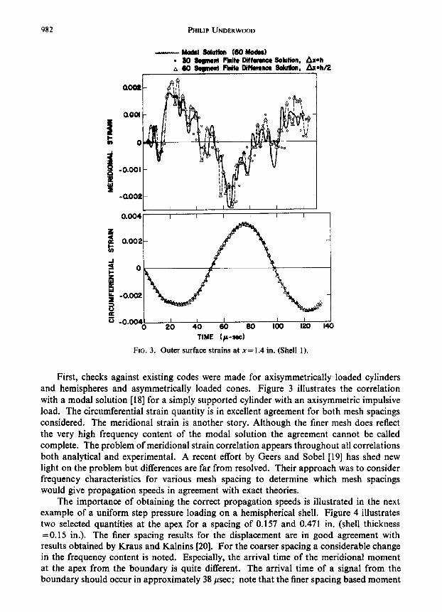
FIG. 3. Outer surface strains at x=1.4 in. (Shell 1).
First, checks against existing codes were made for axisymmetrically loaded cylinders and hemispheres and asymmetrically loaded cones. Figure 3 illustrates the correlation with a modal solution [ 181 for a simply supported cylinder with an axisymmetric impulsive load. The circumferential strain quantity is in excellent agreement for both mesh spacings considered. The meridional strain is another story. Although the finer mesh does reflect the very high frequency content of the modal solution the agreement cannot be called complete. The problem of meridional strain correlation appears throughout all correlations both analytical and experimental. A recent effort by Geers and Sobel 1191 has shed new light on the problem but differences are far from resolved. Their approach was to consider frequency characteristics for various mesh spacing to determine which mesh spacings would give propagation speeds in agreement with exact theories.
The importance of obtaining the correct propagation speeds is illustrated in the next example of a uniform step pressure loading on a hemispherical shell. Figure 4 illustrates two selected quantities at the apex for a spacing of 0.157 and 0.471 in. (shell thickness =0.15 in.). The finer spacing results for the displacement are in good agreement with results obtained by Kraus and Kalnins [20]. For the coarser spacing a considerable change in the frequency content is noted. Especially, the arrival time of the meridional moment at the apex from the boundary is quite different. The arrival time of a signal from the boundary should occur in approximately 38 psec; note that the finer spacing based moment

Transient Response of Inelastic Shells of Revolution 983
is in close agreement while the coarser spacing based moment arrives quite late. So the importance of obtaining the correct frequency characteristics for the finite difference equations is quite readily seen.
_ 0.010
B C
;;
I- 0.006 3 5 3 9r O 8
- 0.005
_o*o,o~ ,I u y y ::f!f 1 0 200 400 600 600 1000
200 1 f-l I
TIME (/L-WC) I
FIG. 4. Response quantities at the apex of a hemisphere (Shell 2).
Through the work of Hartung [5] several investigators have solved the asymmetrically loaded conical frustum problem [5] with fairly unanimous agreement. The comparison for the linear case, Fig. 5, was made with the SABBR-DRASTIC finite element code as a basis. Again, comparisons are good except for the meridional strain. Since this problem has been run by several others, a comparison of run times for the various techniques is available. The data shown in Table 2 is from Ref. [5] with the run times for the SHORE code added. Although the SH0RE code is not competitive with the one-dimensional codes, it is by far the fastest two-dimensional shell dynamics code included in this com- parison. The one-dimensional codes may look attractive for this problem, but the studies which follow on elastic-plastic response make the two-dimensional finite difference tech- nique shine a little brighter.

9x4 PHlLIP UNDERLWIOD
‘-i Ij
-. -----I 500
TIME (p-sac)
FIG, 5. Displacement and meridional stress resultant response at .c-; 6.5 in. and 0 and outer surface meridional strain at x=6.5 in. and PO (Shell 1).
TABLE 2. Summary of computer run times for cone problem%:
Computer code and computer
___~~ .~ Time required to compute I ms of response (min)
-- Linear Nonlinear
SAB0R3-DRASTiC fi
STAR 70 Finite Difference Univac 1108
SMERSH 2D Finite Difference CDC 6400
BALL 1 D Finite Difference IBM 360-67
DYNASBR ID Finite Element IBM 360-55
SHORE 2D Finite Difference Univac 1108
10 (estimated)
30 totai
(not applicable)
fl0 total
30 total (37 min CPU-I-3 min PP1
3.15 exclusive of compile time
5.3 exclusive of compile time
11.2 total R
12.2 total 19.0 total
t Ref. [5]

Transient Respwse of Inelastic Shells of Revolution 955
To look at the various effects of elastic-plastic response several cases are studied for axisymmetric impulsive loads on the simply supported shell considered in the modal correlation. The impulse to cause yielding in this shell is approximately 1500 taps (1000 taps==0.0145 psi-see). Figure 6 illustrates the differences for radial displacement and meridional strain quantities for an elastic and elastic perfectly plastic solution at 3000 taps
loading. The interesting result occurs for the meridional strain quantity, where it is seen that the very high frequency characteristic of the elastic response does not appear in the elastic perfectly plastic result. This result leads one to consider the possibilities of modeling with a coarser mesh for shell response into the plastic regime. For the same shell mesh spacings, Ax’s, of 1, 2, 3, 5 and 10 times the thickness were considered. The results, Fig. 7, are truly amazing. The radial displacement is slightly changed for the very coarse mesh. The meridional strain, the item of difficulty in elastic analysis, also shows very little change for the coarser mesh. Admittedly the details of the shape are different but the peaks and general shape are certainly retained. It would appear that modeling for plastic response is much less critical than for elastic response.
-0.041 I / I I I I I U.l?fJB 1 I
-“~““a*~-- 80 TIME (p-see)
FIG. 6. Displacement and outer surface meridional strain at x= 1.4 in. (Shell 1).
A comparison between elastic perfectly plastic and elastic plastic (linear strain harden- ing) response is shown in Fig. 8 for a 4000 tap axisymmetric load on the same shell. As would be expected the computations based on the strain hardening model predict less strain but the shape of the response is very similar. Therefore the conclusions regarding coarser mesh spacings should still hold for strain hardening models. Also for many practical problems it appears that a suitable choice for the yield stress would make an elastic perfectly plastic analysis quite adequate for engineering purposes.

986 PHILIP UNDERWAY
50 100
TIMC (p-see)
FIG. 7. Displacement and outer surface meridional strain at x:- 3.0 in. (Shell I ).
- Elastic Plastic ---- Elastic Pwtrctly Plastic
k_’ \.“’
-0.020 i I
0 !50 100 is0 ZOO
TIME (~-~rC)
FIG. 8. Outer surface strains at x=1.5 in. (Shell 1).

Transient Response of Inelastic Shells of Revolution 987
A correlation with experimental data was also made for a clamped cylinder (shell number 4) with both blast and impulse asymmetric loadings. The data was supplied by Stanford Research Institute [21, 221. The experimental data for the blast loaded cylinder is not the best in that the data as shown in Fig. 9 has been shifted by 30” to get the peak at 0” and the deformation about 0” is not very symmetric. In spite of the suspected inade- quacy of the data a relatively good correlation of permanent deformation was obtained for both the elastic perfectly plastic and elastic plastic solutions using the nonlinear kine- matics formulation. For 6061-T6 aluminium there is very little strain hardening so the slight difference between the two cases considered was expected. The linear kinematics solution predicts approximately 30 per cent less deformation than the nonlinear kinematics solution. So even for these moderate deformations the nonlinear terms become important.
-0.2 F
f - -0.4 t
- Erpwimntol a SHORE, Elortic-
Portectly Plortic, Caoru Wrh
8 ,, WORE, Elatic- Ploatic (Lineor
a’ Strain Hadming)
E
-0.6 Coorm Mesh
-120 -80 -40 0
SHORE, Elostic- Pwtutly Plastic, Limr Kimmoticr, caorn YIah
FIG. 9. Correlation for blast loaded cylinder (Shell 4)-Deformation at x=L/2 versus circumferential location and 0=0” versus meridional location.
Figure 10 illustrates the very good correlation obtained for a 8400 tap experiment [22]. For these relatively small deflections very little difference between the response based on linear or nonlinear kinematics is predicted. Also note the predictions for the coarse mesh (twice the spacing of the finer mesh)--five times the thickness-are in very good agreement with the experimental data. Although the rippling of the shell obtained in the experiment is not predicted, it is conjectured that by including initial imperfections in the nonlinear kinematics version of the code along with a finer mesh these results can be obtained.

98R PHILIP UNDERWOOD
Computed. Eladic Putrctly Pbrtic
0 Linear Kinematiir o Nonlinear Kinrmatia q Nonlinear Kinmatics, Coarw &ah
-0.15. ’ I 1 I / I -150 -100 -5O 0 50 loo 15O
e (Degreea)
FIG. 10. Correlation for impulse loaded cylinder (Shell 4)--deformation at .Y -L/2 versus circumferential location.
In both experimental-analytical correlations it is seen that the coarse mesh is entirely
adequate for the prediction of permanent deformations. Also for deformations approxi- mately twice the thickness no significant difference between linear and nonlinear kinematic
solutions are seen, but for the larger deformations shown in Fig. 9 the nonlinear kinematic
solution becomes quite important.
CONCLUSION
The lower order finite difference expressions in conjunction with the checkerboard
grid used in the SHORE code is numerically competitive with the higher order differencing schemes used in codes such as STAR [I, 21 while proving to be much more economical. Secondly, the selection of a mesh spacing is much more critical for elastic problems than
for elastic plastic problems. The work of the future lies in understanding the behavior of the meridional strain quantity from an analytical viewpoint and further comparisons of linear and nonlinear kinematic solutions for very large deformations. Hence experimental
data is needed for simple shell structures in the elastic response regime and for large deformation. Especially relevant would be strain gage data for the elastic response cases.
Acknowledgement-The author is indebted to Dr. J. M. Massard for his many discussions on the art and science of finite difference techniques and to Mr. R. F. Walz for providing the opportunity to develop the SH0RE code. The work reported herein was carried out under the Lockheed Missiles & Space Company’s Independent Research Program.
REFERENCES
[I] B. G. WRENN, L. H. SOBEL and W. SI~BY, Nonsymmetric and nonlinear response of thin shells, LMSC B-72-67-3, Lockheed Missiles & Space Co., Palo Alto, California (Dec. 1967).
[2] W. SILSBY, L. H. SOBEL and B. G. WRENN, Nonsymmetric and nonlinear dynamic response of thin shells, Vol. 1, User’s Manual for STAR (Shell Transient Asymmetric Response), LMSC B-70-68-19. Lockheed Missiles & Space Co.. Palo Alto, California (Dec. 1968).
[3] R. D. KRIEQ and H. C. MONTEITH, A large deflection transient analysis of arbitrary shells using finite differences. Proceedings of the Conference on Computer Oriented Analysis of Shell Structures, Lockheed Missiles & Space Co., Palo Alto, California (August, 1970).

Transient Response of Inelastic Shells of Revolution 989
[4] L. MORINO, J. W. LEECH and E. A. WITMER, An improved numerical calculation technique for large elastic-plastic transient deformations of thin shells, Parts 1 and 2. J. appt. Meeh. 423-436 (I971 1.
[5] R. F. HARTUNG, An assessment of current capability for computer analysis of shell structures. AFFDL- TR-71-54 (April 1971).
[6] P. G. UNDERWOOD. User’s guide to the SHORE code. LMSC-D244589, Lockheed Missiles & Space Co., Palo Alto, California (Nov. 1971).
[7] J. L. SANDERS, Jr., An improved first-approximation theory for thin shells. NASA Technical Report R-24 (1959).
[8] J. L. SANDERS, Jr., Nonlinear theories for thin shells. Q. o/J~/. Moth. 21. 21-36 (1963). (91 R. HILL, The Mathemntieal Theory of f/o~ficit)~. Chapter 2. 3, 12, Oxford University Press, London.
(1964). [IO] R. H. FRANKE, CYLINDER, a computer program for the inelastic dynamic response of orthotropic
cylindrical shells, Kaman Nuclear, KN-67-533(R) (Sept. 1967). [II] R. D. KRIEG, Unconditional stability in numerical rime integmtinn methods. Snndia Lahorntnries,
SC-DR-70-400 (Dec. 1970). [12] M. G. SALVADORI and M. L. BARON, Numerical Methods in Enginrerin,r, Prentice-Hall, Englewood
Cliffs, N.J. (1952). [I 31 A. C. CASSELL, Shells of revolution under arbitrary loading and the use of fictitious densities in dynamic
relaxation. Inst. civ. Engrs. Proc. 45, 65-78 (1970). [I41 R. E. BALL, Dynamic analysis of rings by finite differences. Proc. ASCEJ. En~np ~2lcch. Dir. 53, No.
EMl, l-10 (1967). [I51 R. E. BALL, A program for the nonlinear static and dynamic analysis of arbitrarily loaded shells of
revolution. Proceedings of the Conference on Computer Oriented Aria!,,,,, of Shell Structures. Lockheed Missiles & Space Co., Palo Alto, California (August 1970).
[16] L. H. SOREL, private conversations (1968-69). [17] D. U. VON ROSENRERG, Methods for the Numerical Solution of Partiol Diffcrentiol Equarions, American
Elsevier. New York (1969). [I81 P. G. UNDFRWOOD, Dynamic response of simply supported orthotropic Iayercd circular cylindrical
shells to time-dependent loads, Lockheed Missiles & Space Co. Report A819009 (March 1966). [19] T. L. GEERS and L. H. SOREL. Analysis of the transient response of shell structures by numerical methods,
presented at the Symposium on Dynamic Response of Structures, Stanford University (June 1971): aI90 Dynamic Response of‘.Sfructures (edited by George Hermann) Pcrgamon Press, Oxford (Jan. 1972).
[20] H. KRAUS and A. KALNINS, Transient vibration of thin elastic shells. .I. Acoust. Sot. Am. 38, 992-1002 (1965).
[21] H. E. LINDRERCI, private communications (1971). [22] H. E. LINDRERG and G. E. SLITER, Response of reentry-vehicle-type shells to transient surface pressures.
Stanford Research Institute Technical Report No. AFWL-TR-68-56 (June 1969).
(Received 10 February 1972)

![Single-Atomic-Level Probe of Transient Carrier Dynamics by ...1].pdf · spin-polarized STM (SP-STM) has been combined with the inelastic excitation of electrons, and spin dynamics](https://static.fdocuments.in/doc/165x107/5f5d57cd5aa223279c21976d/single-atomic-level-probe-of-transient-carrier-dynamics-by-1pdf-spin-polarized.jpg)


![A Discrete Model for Inelastic Deformation of Thin Shellsmrl.nyu.edu/~dzorin/papers/secord2004sds.pdf · A Discrete Model for Inelastic Deformation of Thin Shells ... [COPar] use](https://static.fdocuments.in/doc/165x107/5aa7093d7f8b9aee748b8aaa/a-discrete-model-for-inelastic-deformation-of-thin-dzorinpaperssecord2004sdspdfa.jpg)