TRANSIENT LIQUID PHASE BONDING - Eagar Group - MIT
24
Annu. Rm. Muter. Sci. 1992.22:23-46 Copyright 0 1992 by Annual Reviews Inc. All righis reserved TRANSIENT LIQUID PHASE BONDING W. D. MucDonald and T. W. Eagar r> Department of Materials Science and Engineering, Massachusetts Institute of Technology, Cambridge, Massachusetts 02 139 KEY WORDS: diffusion, diffusion welding, activated diffusion bonding, iso- thermal solidification INTRODUCTION Transient liquid phase (TLP) bonding is a joining process that has been applied to many metallic systems throughout the ages, and yet it still holds promise as a technique for joining in aerospace and semiconductor applications. The TLP process produces a strong, interface-free joint with no remnant of the bonding agent. It differs from diffusion bonding in that the formation of a thin liquid interlayer eliminates the need for a high bonding or clamping force. The interlayer can be provided by foils, electro- plate, sputter coats, or any other process that deposits a thin film on the faying surfaces. A schematic illustration of the process, shown in Figure 1, indicates that by placing a thin interlayer of an alloying metal containing a melting point depressant (MPD) between the two pieces of parent metal to be joined and heating the entire assembly, a liquid interlayer is formed. The liquid may form because the melting point of the interlayer has been exceeded, or because reaction with the parent metal results in a low melting liquid alloy. The liquid then fills voids formed by unevenness of the mating 4 surfaces and can sometimes dissolve residual surface contamination. With time the MPD diffuses into the parent metal resulting in isothermal solidi- fication. Upon cooling there remains no trace of the liquid phase, and ideally the joint becomes indistinguishable from other grain boundaries: It is illustrative to use a phase diagram to explain the process as was done by Tuah-Poku et a1 (1). In their paper, four stages corresponding to composition regimes on the phase diagram were delineated, although in
Transcript of TRANSIENT LIQUID PHASE BONDING - Eagar Group - MIT
Annu. Rm. Muter. Sci. 1992.22:23-46 Copyright 0 1992 by Annual Reviews Inc. All righis reserved
TRANSIENT LIQUID PHASE BONDING
W. D. MucDonald and T. W. Eagar
r> Department of Materials Science and Engineering, Massachusetts Institute of Technology, Cambridge, Massachusetts 02 139
KEY WORDS: diffusion, diffusion welding, activated diffusion bonding, iso- thermal solidification
INTRODUCTION
Transient liquid phase (TLP) bonding is a joining process that has been applied to many metallic systems throughout the ages, and yet it still holds promise as a technique for joining in aerospace and semiconductor applications. The TLP process produces a strong, interface-free joint with no remnant of the bonding agent. It differs from diffusion bonding in that the formation of a thin liquid interlayer eliminates the need for a high bonding or clamping force. The interlayer can be provided by foils, electro- plate, sputter coats, or any other process that deposits a thin film on the faying surfaces.
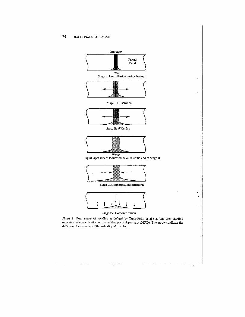
A schematic illustration of the process, shown in Figure 1, indicates that by placing a thin interlayer of an alloying metal containing a melting point depressant (MPD) between the two pieces of parent metal to be joined and heating the entire assembly, a liquid interlayer is formed. The liquid may form because the melting point of the interlayer has been exceeded, or because reaction with the parent metal results in a low melting liquid alloy. The liquid then fills voids formed by unevenness of the mating
4 surfaces and can sometimes dissolve residual surface contamination. With time the MPD diffuses into the parent metal resulting in isothermal solidi- fication. Upon cooling there remains no trace of the liquid phase, and ideally the joint becomes indistinguishable from other grain boundaries:
It is illustrative to use a phase diagram to explain the process as was done by Tuah-Poku et a1 (1). In their paper, four stages corresponding to composition regimes on the phase diagram were delineated, although in
24 MACDONALD & EAGAR
Interlaver
W o Stage 0: Interdiffusion during heatup.
Stage I: Dissolution
Stage 11: Widening
Stage 111: Isothermal Solidification
Stage IV: Homogenization
Figure 1 Four stages of bonding as defined by Tuah-Poku et a1 (I). The grey shading indicates the concentration of the melting point depressant (MPD). The arrows indicate the direction of movement of the solid-liquid interface.
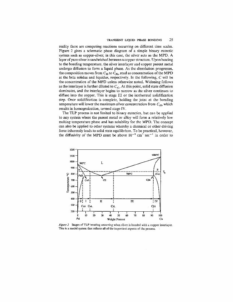
reality there are competing reactions occurring on different time scales. Figure 2 gives a schematic phase diagram of a simple binary eutectic system such as copper-silver; in this case, the silver acts as the MPD. A layer of pure silver is sandwiched between a copper structure. Upon heating to the bonding temperature, the silver interlayer and copper parent metal undergo diffusion to form a liquid phase. As the dissolution progresses, the composition moves from Cgg to Cm, read as concentration of the MPD at the beta solidus and liquidus, respectively. In the following, C will be the concentration of the MPD unless otherwise noted. Widening follows as the interlayer is further diluted to CUT. At this point, solid state diffusion dominates, and the interlayer begins to narrow as the silver continues to diffuse into the copper. This is stage I11 or the isothermal solidification step. Once solidification is complete, holding the joint at the bonding temperature will lower the maximum silver concentration from CEs, which results in homogenization, termed stage IV.
The TLP process is not limited to binary eutectics, but can be applied to any system where the parent metal or alloy will form a relatively low melting temperature phase and has solubility for the MPD. The concept can also be applied to other systems whereby a chemical or other driving force inherently leads to solid state equilibrium. To be practical, however, the diffusivity of the MPD must be above 1 0 8 cm2 s e c ' in order to
0 1 0 2 0 3 0 4 0 5 0 6 0 7 0 8 0 9 0 1 0 0 Ag Weight Percent Cu
Figure 2 Stages of TLP bonding occurring when silver is bonded with a copper interlayer. This is a model system that reflects all of the important aspects of the process.
achieve complete solidification in reasonable times (2). In essence, any system wherein a liquid phase disappears by diffusion, amalgamation, volatilization, or other processes is a candidate for TLP bonding.
The joining of metals using a transient interlayer dates back to ancient times. Granulation, as described by Cellini (3) in the sixteenth century, used copper oxide paint as the interlayer along with some tallow or glue to hold small gold balls on to a gold article such as a vase and act as a flux. The article was then heated in a reducing flame, which rendered the copper available to form an eutectic with gold. After homogenizing in the flame, an invisible diffusion bonded structure resulted. Recipes for the process are given in the twelfth century work by Theophilus, entitled De Re Deversis Artibus (4) . Reference is made in the eighth century Mappae Clavicula (5), or the Little Key to Medieval Arts, to a similar process. It has been suggested by Smith (6) that the ornamentation on King Tutankh- amen's gold dagger dating from 2500 B.C. was created using the process of granulation. The Etruscans were able to join decorative gold beads to gold articles using the same process. It is interesting to note that this first use of the TLP process was based on an isomorphous azeotropic system, whereas modem theory has been developed for binary eutectic systems. A very similar process was patented in 1933 by Littledale (7), whereby a mixture of oxide, fish glue, and water was used as the bonding agent. The glue allowed small parts to be cemented and also provided carbon to reduce the oxide at the bonding temperature.
A description of the theoretical aspects of the TLP process, especially the kinetics, is presented below. This is followed by a discussion of experi- mental measurements of the interface motion, which do not always agree with the theoretical predictions. Modern applications are then described in terms of the alloy system for which the process was developed and, finally, potential new uses are discussed.
THEORY
Several models have been proposed to describe the kinetics of the process. These are analytical descriptions based on Pick's laws using mass balance arguments, generally limited to a description of stages I and 111, dissolution and isothermal solidification, respectively. In the following, the analytical models are reviewed with a discussion of numerical results where applicable.
Thin Film Approach Wells (8) used the thin film diffusion equation as a first approximation to the TLP process for joining titanium with copper where the concentration profile, C(x, t) was given as
where a is the surface concentration in g/cm3, D is the diffusivity in cm2 sec"' x is the distance from the centerline in cm, and t is the time in seconds. From Equation 1 the maximum concentration at position x = 0 is Cmax, where
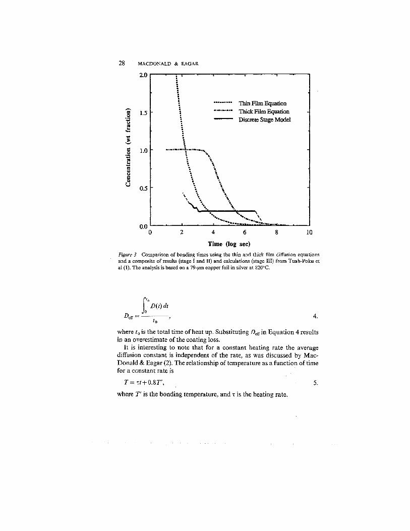
Through a series of fortuitous errors, Wells found that Equation 2 accurately predicted the correct bonding time, whereas in reality the actual bonding time using the correct values is almost 15 times longer. The thin film equation fails because the concentration of the MPD rapidly drops to the concentration at the a-rich liquidus by the process of dissolution. For this reason the thick film equation (9) also does not accurately describe the process. Figure 3 is a comparison of the predicted Cmax values, for the silver-copper system, as a function of time using the thin and thick film equations and the stage model. It is apparent that if an alloy interlayer is used, the thin film equation will predict a decrease in the concentration immediately, whereas in reality the concentration in the interlayer remains constant during the solidification stage.
Discreet Stage Approach The TLP process was first clearly described as consisting of four stages by Tuah-Poku et a1 (I), although other workers had already separated the process into individual stages. Here, Stage 0 is introduced to include the effects of heat up.
STAGE o Niemann & Garrett (10) were concerned with the loss of an electroplated copper interlayer experienced during heat up. The samples were aluminum-boron composites designed to be bonded in a sandwich structure. Following Darken & Gurry's analysis (1 l), the total amount of copper, the MPD, lost to the aluminum matrix was determined to be
where Wioss is the coating loss. This analysis is valid for constant temperature conditions, and actual coating losses were determined experimentally by electron microprobe. These experimental results can be compared with those attained by determining an effective diffusion coefficient, D&, following the method of Shewmon (12), where Deff is given by
Time (log sec)
Figure 3 Comparison of bonding times using the thin and thick film diffusion equations and a composite of results (stage I and XI) and calculations (stage 111) from Tuah-Poku et a1 (1). The analysis is based on a 79-pm copper foil in silver at 820°C
where t o is the total time of heat up. Substituting DeH in Equation 4 results in an overestimate of the coating loss.
It is interesting to note that for a constant heating rate the average diffusion constant is independent of the rate, as was discussed by Mac- Donald & Eagar (2). The relationship of temperature as a function of time for a constant rate is
where T' is the bonding temperature, and T is the heating rate.
Shewmon (12) has shown that below 80% of the bonding temperature the contribution to the diffusive flux is negligible. Substituting this equation along with the standard Arrhenius form of the diffusion constant into Equation 4 gives
where Do is the pre-exponential, Q is the activation energy for diffusion, and R is the gas constant. From Equation 6 it is apparent that the heat up rate cancels. The analytical solution of the integral is a slowly con- verging series function given by
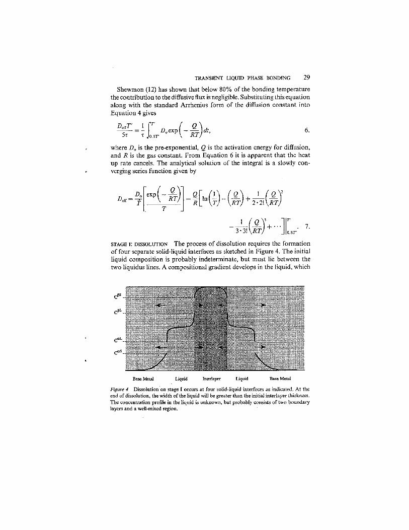
STAGE I: DISSOLUTION The process of dissolution requires the formation of four separate solid-liquid interfaces as sketched in Figure 4. The initial liquid composition is probably indeterminate, but must lie between the two liquidus lines. A compositional gradient develops in the liquid, which
Base Metal Liquid Interlayer Liquid Base Metal
Figure 4 Dissolution on stage I occurs at four solid-liquid interfaces as indicated. At the end of dissolution, the width of the liquid will be greater than the initial interlayer thickness. The concentration profile in the liquid is unknown, but probably consists of two boundary layers and a well-mixed region.
30 MACDONALD & EAGAR
in turn produces a rapid diffusive flux. Therefore early in the process, the liquid composition is controlled by atomic movement at the interface rather than diffusion through the liquid interlayer. Tuah-Poku et a1 (1) modeled stage I, assuming liquid diffusion control, using a general square root law, such that the movement of the interface was given as
where Y , is the position of the solid liquid interface, K l is a constant derived from the phase diagram, and DL is the diffusivity in the liquid, which follows from the solution to Pick's second law. Accordingly, the width of the liquid zone becomes equal to the width of the interlayer when Y , is equal to the half width such that
where Wo is the initial interlayer width. Upon substituting appropriate values using a 79-pm foil, a dissolution time of about three seconds was determined. This model assumes that the dissolution front grows into the interlayer and that the process is complete once the interlayer is liquid. That this assumption is not valid follows from consideration of the phase diagram, which indicates that to obtain a completely liquid phase, the copper concentration of the interlayer must be lowered to Cai. Hence, at 820°C the interlayer must widen by over two and one half times before it is completely liquid. In reality, there are four solid-liquid interfaces as sketched in Figure 4.
Nakao et a1 (1 3), using the Nernst-Brunner theory (14), determined an activation energy for dissolution in stage I. The concentration dependence of the interlayer with time was given as
where K is a dissolution rate constant, A is the surface area of solid, and V is the volumeof liquid interlayer. Equation 10 predicts that at long times the concentration of the diffusing species in the liquid phase will asymptotically approach the equilibrium value as given by the phase dia- gram. By differentiating Equation 10 and substituting in the appropriate constants, an expression relating the dissolution rate and the interface displacement is

TRANSIENT LIQUID PHASE BONDING 31
where P is the dissolution parameter, W is the instantaneous interlayer width, Wmm is the maximum interlayer width, p is the ratio of liquid to solid density, apd W, is the initial interlayer width. A linear dependence of the dissolution parameter with time was demonstrated for the superalloy MM 007 with a Ni-Cr-B interlayer. However, Equation 11 predicts that at long times dissolution will continue without bound. The Nernst-Brunner theory was formulated for a semi-infinite solid being dissolved in a finite liquid bath, whereas Equation 10 indicates that at long times the liquid will saturate with respect to the remaining solid. A linear relation is valid only until all the solid has dissolved, but since there are two solids involved, it is surprising that a linear relatio,n is obtained. The thermal dependence of K given as
where Q is the activation energy in J m o l l , R is the gas constant in J m o l l K ', and T is bonding temperature in Kelvin. An activation energy of 682 J m o l l was obtained from a plot of ln K vs l/T, which is greater than would be expected for a diffusion controlled process. But since K does not correspond directly to a physical process, the activation energy that is derived may not have much meaning. A straight line fit to the data is unwarranted, since at high and low temperatures K will go to infinity and zero, respectively, as dictated by the phase diagram. Also, in the same paper an activation energy of 226 kJ m o l l is reported for diffusion of boron into the nickel base alloys. Nakagawa et a1 (15) suggested that the Nernst-Brunner theory does not hold when the width of the required thin boundary layer is wider than the liquid interlayer, and thus there is no bulk liquid. At this time it is unclear what mechanisms control the dissolution process.
Liu et a1 (16) have outlined an analytic model that accounts for the fact that the dissolution front proceeds into the interlayer as well as the parent metal. A mass balance on the system gives the velocity of each interface as

32 MACDONALD & EAGAR
where Y\ refers to the position of the ith interface. Dissolution is controlled by the rate at which element B diffuses into the quiescent liquid as con- trolled by Fick's second law
which has the general solution,
subject to the appropriate boundary conditions. Equations 15 and 16 imply that the interface movement can be described as
and
which in turn gives an expression for the interface velocity as
and
By rearranging and combining these equations an expression for the con- centration gradient at the interface becomes
and
22.
By substituting the expressions for the interface velocities, Equations 19 and 20, and concentration gradients, Equations 21 and 22, into the mass
-
TRANSIENT LIQUID PHASE BONDING 33
balance, Equations 13 and 14? two explicit functions of the dimensionless growth constants are obtained as
A ~ G { exp ( G { ~ - G ~ ) - G: = 0 23.
and
where
and
The simultaneous equations are solved numerically to obtain values for the growth constants. Thus the time at which the interlayer is consumed is given by
and the half width of the liquid interlayer at this instant is given as
wL w~+~G;&. 28.
Using Liu et al's equations? the time for complete dissolution of the foil is still on the order of seconds, as was calculated by Tuah-Poku et a1 (1).
Nakagawa et a1 (1 5) developed a numerical model of heat up, dissolu- tion, and widening using an explicit forward finite difference approach. The model was devised to distinguish between constant and unrestrained interlayer widths. A constant interlayer width results when some form of an inert spacer is inserted between clamped faying surfaces. The time to completion for unrestrained dissolution was found to be about five times longer than for constant interlayer width. In each case, dissolution time was found to be proportional to the square of the filler metal thickness. The advance of the solid-liquid interface is approximately related to the inverse of the square root of the solute diffusivity in the liquid and not to the diffusivity in the solid. The influence of heating rate above the eutectic temperature was found to be dependent on the thickness of the filler metal. Decreasing the heating rate resulted in less dissolution for a thin interlayer and more dissoIution for a thick interlayer.
34 MACDONALD & EAGAR
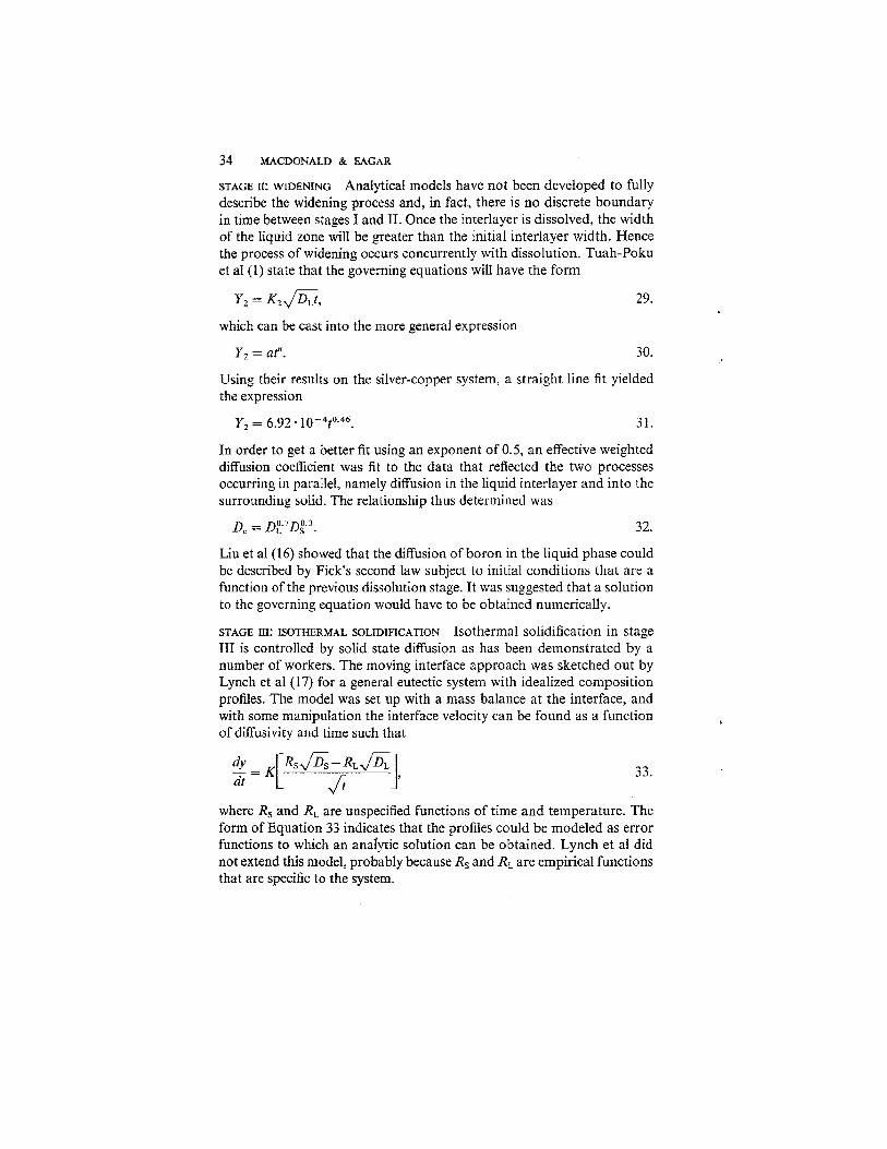
STAGE II: WIDENING Analytical models have not been developed to fully describe the widening process and, in fact, there is no discrete boundary in time between stages I and 11. Once the interlayer is dissolved, the width of the liquid zone will be greater than the initial interlayer width. Hence the process of widening occurs concurrently with dissolution. Tuah-Poku et a1 (1) state that the governing equations will have the form
which can be cast into the more general expression
Y2 = af".
Using their results on the silver-copper system, a straight line fit yielded the expression
In order to get a better fit using an exponent of 0.5, an effective weighted diffusion coefficient was fit to the data that reflected the two processes occurring in parallel, namely diffusion in the liquid interlayer and into the surrounding solid. The relationship thus determined was
Liu et a1 (16) showed that the diffusion of boron in the liquid phase could be described by Fick's second law subject to initial conditions that are a function of the previous dissolution stage. It was suggested that a solution to the governing equation would have to be obtained numerically.
STAGE 111: ISOTHERMAL SOLIDIFICATION Isothermal solidification in stage I11 is controlled by solid state diffusion as has been demonstrated by a number of workers. The moving interface approach was sketched out by Lynch et a1 (17) for a general eutectic system with idealized composition profiles. The model was set up with a mass balance at the interface, and with some manipulation the interface velocity can be found as a function of diffusivity and time such that
where Rs and RL are unspecified functions of time and temperature. The form of Equation 33 indicates that the profiles could be modeled as error functions to which an analytic solution can be obtained. Lynch et a1 did not extend this model, probably because Rs and RL are empirical functions that are specific to the system.
TRANSIENT LIQUID PHASE BONDING 35
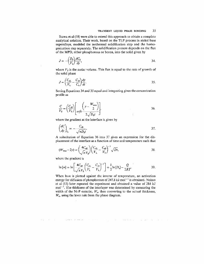
Ikawa et a1 (18) were able to extend this approach to obtain a complete analytical solution. Their work, based on the TLP process in nickel base superalloys, modeled the isothermal solidification step and the homo- genization step separately. The solidification process depends on the flux of the MPD, either phosphorous or boron, into the solid given by
where Vs is the molar ~olume. This flux is equal to the rate of growth of the solid phase
Setting Equations 34 and 35 equal and integrating gives the concentration profile as
where the gradient at the interface is given by
A substitution of Equation 36 into 37 gives an expression for the dis- placement of the interface as a function of time and temperature such that
where the gradient is
When lnm is plotted against the inverse of temperature, an activation energy for diffusion of phosphorous of 247.8 kJ mol- ' is obtained. Nakao et a1 (13) later repeated the experiment and obtained a value of 284 kJ mol-I. The thickness of the interlayer was determined by measuring the width of the Ni-P eutectic, We, then converting to the actual thickness, We, using the lever rule from the phase diagram.

36 MACDONALD & E A G a
In this work, the width of the interlayer was held constant by molyb- denum wire spacers. As Nakagawa et a1 (1 5) pointed out, the solidification time is shorter for the constrained width method used here. The time required for isothermal solidification, t3 , was derived by Nakao et a1 (13) as
A straight line fit was obtained in t ; I 2 vs Wmax/D'12 plots, but the kinetics are an order of magnitude faster than would be obtained using a reasonable pre-exponential factor for the diffusivity. Tuah-Poku et a1 (1) derived a slightly different governing equation for the variable width case. They found that the maximum width of the interlayer could be derived from the mass balance relationship
where Wo is the initial interlayer width, Wmax is the maximum interlayer width, and pips are the densities of the interlayer and the parent metal, respectively. Upon rearranging, Wmax was found to be 4.9 Wo, which is close to the experimentally obtained value of 5.3 Wo, the difference arising partly because the change in density during liquefaction was taken into account. Once again, the interface kinetics were modeled through the use of a general relation such that
The experimental value of K3 was found to be nearly three times that derived from the phase diagram. It was suggested that this discrepancy was the result of the solidification process, possibly involving a ledge-type migration mechanism, wherein the diffusional mobility of the interface is then controlled by the two-dimensional nucleation and growth of ledges, which involves a cooperative movement of groups of atoms. This process was said to speed up the advancement of the solid liquid interface and reduce the time needed for solidification. However, it should be a slower process than if each atom could attach at any site.
An estimate for the time required for the completion of solidification using a mass balance under the assumption that the densities were equal was given as
W C a ~ = WmaxCgL + 2 Ds - dt. l':

TRANSIENT LIQUD PHASE BONDING 37
The error function solution for concentration derived earlier is then inserted into the integral and an expression for solidification becomes
Using their experimental conditions, namely a 79-pm copper foil in silver at 82WC, Equation 44 predicts a time of 1200 hr as compared to the experimental extrapolated value of about 200 hr. This suggests that either the experimental method allowed some loss of the liquid interlayer, or some other solidification mechanism was operating. Writing Equation 44 explicitly to show the dependence of solidification time on temperature gives
As the temperature increases, the diffusivity increases via the exponential term, but the concentration CEs decreases, causing greater widening. By approximating the solidus as a straight line, a linear relationship is obtained between CEs and temperature. Substituting this into Equation 45, then taking the first derivative set to zero, gives an expression for the minimum solidification time temperature as
where l /n is the slope of the solidus and Cis a constant derived from the phase diagram equal to CnETM/(TMaTE). The temperature dependence was determined for several systems, but no experimental verification of this behavior has been presented. The maximum alloy concentration at this minimum may exceed the maximum allowable design concentration, thus requiring further homogenization time. A higher bonding temperature will result in a lower final concentration, which indicates that there is a trade-off in selecting the process temperature. The total isothermal solidi- fication time is then
when starting with a pure metal interlayer. Ramirez & Liu (19) performed TLP bonding experiments with the

nickel-boron system and found that there were two distinct regimes of solidification behavior. A faster initial regime had a displacement rate ten times as great as the second regime. That the interface will slow with time is apparent from consideration of Equations 12 and 13, which show that the displacement rate varies with the inverse root of time. The two distinct regimes that were found suggest that at early times excess liquid was being squeezed out of the joint. Despite this, an activation energy of 166 kJ m o l ' was obtained, which is significantly lower than the values reported earlier by Nakao et a1 (13) and Ikawa et a1 (18).
STAGE IV: HOMOGENIZATION There have been no explicit models developed to describe homogenization during TLP bonding. Homogenization of cast alloys in general, however, is a well-studied subject from which suitable models can be selected. The bonding temperature at which a specified maximum allowable concentration of the MPD is achieved in the minimum amount of time is not necessarily the same as that for the minimum in the solidification time.
EXPERIMENTAL
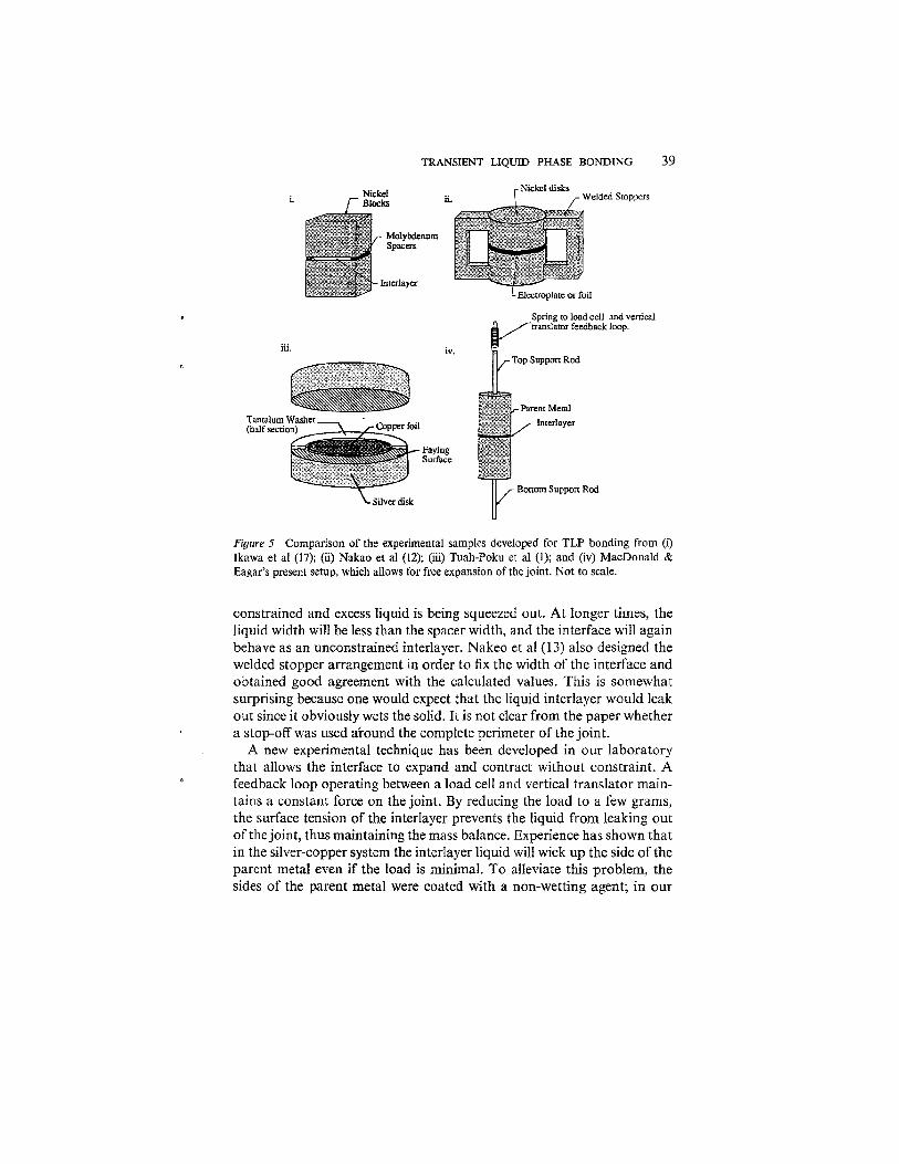
Interface Kinetics Measurement of the interface migration rate has been accomplished three different ways as shown in Figure 5. The earliest approach taken by Tuah- Poku et a1 had a tantalum washer to maintain a minimum spacing held in place by a miniature clamp. Their results indicated that the interlayer widened in an unconstrained manner, exceeding the theoretical maximum width as given by Equation 33. This is surprising since one would expect that the action of the clamp and washer would be to fix the interlayer width at the thickness of the tantalum foil used. That it did not do so indicates that lateral dissolution of the silver was not a factor. The extrapo- lated isothermal solidification time obtained was considerably shorter than the calculated time. Tuah-Poku et a1 suggest that this is due to the complex conditions prevailing at the interface. Another possible explanation is that the liquid interlayer leaked out of the joint region.
Nakao et a1 (13) used a hot press to hold samples together with a molybdenum wire spacer inserted to fix the liquid width. Under load, the liquid was extruded from the joint region, which reduced the overall solidification time. The accuracy of this measurement method would be reduced if there were deformation of the solid nickel alloy around the wire. There should also be a step in the interface displacement vs time plot. The solidification kinetics will be faster at the start when the interface is
TRANSIENT LIQUID PHASE BONDING 39
Spring to load cell and vertical translator feedback loop.
iii. iv.
Tantalum (half secti
Faying Surface
Bottom Support Rod
Figure 3 Comparison of the experimental samples developed for TLP bonding from (i) Ikawa et a1 (17); (ii) Nakao et a1 (12); (iii) Tuah-Poku et a1 (1); and (iv) MacDonald & Eagar's present setup, which allows for free expansion of the joint. Not to scale.
constrained and excess liquid is being squeezed out. At longer times, the liquid width will be less than the spacer width, and the interface will again behave as an unconstrained interlayer. Nakeo et a1 (13) also designed the welded stopper arrangement in order to fix the width of the interface and obtained good agreement with the calculated values. This is somewhat surprising because one would expect that the liquid interlayer would leak out since it obviously wets the solid. It is not clear from the paper whether a stop-off was used around the complete perimeter of the joint.
A new experimental technique has been developed in our laboratory that allows the interface to expand and contract without constraint. A feedback loop operating between a load cell and vertical translator main- tains a constant force on the joint. By reducing the load to a few grams, the surface tension of the interlayer prevents the liquid from leaking out of the joint, thus maintaining the mass balance. Experience has shown that in the silver-copper system the interlayer liquid will wick up the side of the parent metal even if the load is minimal. To alleviate this problem, the sides of the parent metal were coated with a non-wetting agent; in our
40 MACDONALD & EAGAR
case, chromium on copper with a silver interlayer. This method also prevents Kirkendall porosity, which develops when the two parent metals are constrained at a fixed distance.
Grain Size Effect Kokawa et al (20) were able to show a distinct effect of grain size and orientation on the solidification process. Pure nickel samples with grain sizes of 4 mm and 40 pm were TLP bonded with a 38-pm thick nickel- phosphorous interlayer at 1200 K for 2.75 hr. The interlayer width of the fine grain sample was 9 vs 18 pm for the coarse grain sample. The liquid penetration into the boundary was also shown to be a function of grain boundary orientation. A saw-toothed solid-liquid interface shape de- veloped with cusps at each grain boundary. The cusps are a result of surface tension effects as the liquid preferentially wets the grain boundaries. It was claimed that the resulting increase in the surface area of the interface promoted faster solidification in the fine-grained sample. It is also likely that phosphorous has a higher diffusion rate along grain boundaries. The rapid grain boundary diffusion enhances the migration rate of the MPD. An effective diffusion constant could be obtained from a rule-of-mixtures approach so that
D e f r = + A g f A b , 48.
where the subscripts refer to lattice and grain boundary.
Diffusion Profiles Concentration profiles of the MPD have been obtained for several bonding systems including titanium and nickel superalloys (1, 10, 18, 21, 22). Ikawa & Nakao (23) were the first to show the concentration profile of phosphorous in a nickel joint becoming flat after a 16 hr hold at 1200°C In general, an asymptotic approach to equilibrium is observed although the parent metal alloy composition is not reached. Even after extended homogenization, a slight variation on the composition can be seen at the original bond line. Analytical models usually predict less diffusion at early times, whereas some numerical models seem to agree more closely with the data (24).
Solidzfication Front It is not yet clear how the solid front advances into the liquid interlayer. Tuah-Poku et a1 suggest that grain growth is by a ledge-type mechanism that enhances the solidification rate. The presence of a cellular structure is often observed in specimens quenched from stage 111. Some of these cells align with grain boundaries and are manifestations of the wetting
phenomenon discussed earlier. Cells not associated with grain boundaries have been observed in samples with large grains, e.g. 4 mm, which suggests that there may be another reason. Cellular growth in eutectic alloys caused by constitutional supercooling is well known (25), hence impurities in the interlayer causing solute buildup at the interface may be responsible for these cellular structures.
APPLICATIONS
Titanium In 1955, while preparing silver-brazed joints, Tiner (21), working at North American Aviation, noticed that by bonding at high temperatures and long times silver could not be detected at the interlayer. Joints with ex- tremely high shear strengths were formed, although the grain growth slightly impaired the base metal properties. In 1959, Lynch et a1 (17) repeated the process by bonding titanium, using an unspecified alloy as an interlayer. Although no specific processing conditions were given, a series of micrographs revealed the progressive dissolution of the interlayer and the eventual formation of a joint that was "effectively just a grain boun- dary."
The NOR-TI-BOND process reported by Wu (26), based on a patent by Wells & Mikus (27), was developed by Northrop in 1971 for bonding titanium I and T beams, channels, and other structural shapes. The two- step process used local resistance heating to melt an electrolytically deposited copper interlayer. Subsequently, a diffusion treatment at 927OC for four hr reduced the peak copper content from 70 to below 6%, which produced a strong, tough joint. Freedman (28), in an extensive account of the mechanical properties of these joints, showed that parent metal strengths could be achieved using the optimum coating thickness and processing conditions. The plane strain fracture toughness varied from 40 to 90% of that for annealed Ti-6Al-4V. No effect on stress corrosion cracking susceptibility was observed.
Liquid interface diffusion (LID) bonding (also termed Rohr bonding) was developed by Rohr industries to bond titanium honeycomb sandwich structures using nickel-copper interiayers. Schwartz (29) showed how large structures containing several components, such as a jet engine case, are formed in one step. As of 1986 over 5000 engine ducts had been produced using this technology (22). The interlayer was originally deposited, but now 25-pm alloy foils are used, which melt congruently at the bonding temperature, thus avoiding dissolution. Fixturing of the joints is provided by thermal expansion controlled tooling, which on heating places the joint

in compression. The tensile properties of the joints are dependent on the surface finish, therefore a smoother finish results in stronger joints.
Nickel Superalloys Activated diffusion bonding was described by Hoppin & Berry (30) in 1970 for joining nickel base superalloys. This is the earliest reference to the TLP bonding with a melting point depressant (MPD). Interlayer compositions were prepared with the same nominal composition as the parent metal except for the addition of an unspecified MPD, probably boron or phos- phorous. Several superalloys were joined, including Renh 80, and subjected to stress-rupture tests. Joint strengths of 70-90% of the parent metal were obtained, but ductilities were low.
Using nickel-copper interlayers, Duvall et a1 (31), working at Pratt and Whitney, were able to diffusion weld the superalloy Udimet 700 without forming a brittle gamma prime precipitate at the interface. Interface-free welds were achieved using an electroplated nickel-cobalt interlayer with joint efficiencies approaching 100%. The process, patented by Owczarski et a1 (32), reportedly occurred in the solid state, but was more likely a TLP process. Subsequently this was clarified by Duvall et a1 (33) who, using the same materials, coined the term TLP. The patented process (34) was applied to turbine vane clusters used in the low pressure end of a jet engine. Joint efficiencies of 100% were achieved. Adam & Steinhauser (35) showed how this process could be applied to make and repair compound turbine vanes.
Nakao et a1 (36) extended the concept to include the use of a powder addition to the interlayer in order to reduce the solidification time. Termed transient liquid insert metal (TLIM) diffusion bonding, the process time was reduced by over two orders of magnitude as compared to the con- ventional method of TLP bonding superalloys. Suzumura et a1 (37) found that by using amorphous alloy interlayers close to the composition of the parent metal, solidification times were reduced. Joint efficiencies of 100% were also obtained.
Viskov et a1 (38) used a niobium powder interlayer, which forms a liquid phase with the nickel superalloy Kh20N80 at 1200°C After 36 hr of annealing, only a few particles of (Ni,Ci^Nb remained at the interface. The authors ruled out the use of phosphorous or boron as the MPD because of the adverse influence these elements have on mechanical prop- erties, which contrasts with previous investigations.
Dissimilar Metals A concept similar to TLP was developed by Owczarski (39) in 1961 for joining Zircaloy 2 to 304 stainless steel. At that time, no suitable braze
TRANSIENT LIQUID PHASE BONDING 43
filler metals had been found. The two materials were simply butted up to one another forming a liquid phase by a diffusion controlled eutectic reaction. The three major components, iron, chromium and nickel, formed low melting eutectic liquids with zirconium, and the nominally quaternary system 304-Zr formed a liquid at 980°C The joints so produced had fair strength and good corrosion resistance, but lacked ductility. This latter drawback was the consequence of forming intermetallic compounds at the interface. Other dissimilar metals such as aluminum and titanium have been joined in this manner, as described by Enjo et a1 (40). It is not really a TLP process because at long times the joint does not solidify, but rather continues to dissolve the parent metals.
Andryushechkin & Dahkova (41) investigated isothermal solidification of titanium coatings on steel to provide a protective coating. The interlayer width was only dependent on the width of the initial paste and consisted of an a-solid solution of Fe in Ti, FeTi intermetallic, and T i c particles. Contact melting occurred rapidly, thus making it difficult to control the structure and properties of the coating. Longer hold times resulted in an increase in both the size and volume fraction of titanium carbide particles.
Eagar (42) reported joining of copper to molybdenum using copper- gold-nickel interlayer alloys. By use of a circular geometry, which creates large compressive stresses on the liquid interlayer because of the thermal expansion of the two base metals, a very thin liquid region is produced that creates a TLP bond within a few tens of seconds. In this case, the gold diffuses only into the copper base metal and not into the molybdenum.
A completely different approach was proposed by Zhang et a1 (43) to join dissimilar metals. Termed instantaneous liquid phase (ILP) bonding, the process rapidly forms a thin liquid film on non-contacting faying surfaces, then quickly closes the joint and rapidly cools the parts. Unlike TLP, very little diffusion occurs, thus preventing the formation of un- desirable intermetallic compounds.
Semiconductors In 1966, Bernstein (44) and Bernstein & Bartholomew (45) developed the solid-liquid inter-diffusion (SLID) process for joining semiconductor components. The process was divided into five stages, namely, wetting, alloying, liquid diffusion, gradual solidification, and solid diffusion. It was concluded that bonding occurred as a result of interdiffusion, but no quantitative analysis was performed. Evaluation of the joints consisted of determining the unbending temperature, i.e. the temperature at which a joint would reliquefy and fail under a shear load. The scatter in their results was an indication of intermetallic formation by amalgamation, as discussed by MacDonald & Eagar (2). SLID bonding was designed to
44 MACDONALD & EAGAR
overcome the limitations imposed during device fabrication where each sequential joining operation has to be performed at a lower temperature.
Roman (46) investigated low temperature TLP bonding as a method for surface mounting of semiconductor chips. In this process, as in SLID bonding, the solidification reaction occurs as a result of intermetallic formation and not by diffusion of the MPD. Shear tests showed con- siderable scatter, which indicated that it is difficult to control the extent of bonding. To be an effective process, selection and control of the inter-
)
metallic formation are required.
Composites f
Niemann & Garrett (lo), of McDonnell-Douglas, described eutectic bond- ing as a reliable low pressure, low temperature method for fabricating aluminum-boron composites with a copper interlayer. Titanium to alumi- num joints were also made, achieving moderate properties; however a 0.040" reaction zone of intermetallics was observed. Evaluation of the joint was by a three point interlaminar shear bending test.
Klehn (47) applied the TLP process to aluminum metal matrix composites. A marked difference in the joint structure was noted between pure metal and alloy interlayers. A zone of high particulate density was produced along the bond line as a result of excess dissolution and squeezing out of the base metal. This effect was minimized when alloy interlayers such as aluminum-silicon eutectic were used. Again, a dependence on the surface finish was noted; smooth machined surfaces provided the strongest joints.
Other Systems A transient liquid phase was used to bond aluminum-lithium alloys as described by Ricks et a1 (48). A roll-clad zinc base alloy interlayer was used to overcome the tenacious surface oxide. The process was amenable to producing superplastic components. There are several other related processes that act in the same manner as TLP bonding. These are amal- gamation, transient liquid phase sintering, as applied to powdered metals t
(49) and ceramics (SO), and diffusion solidification (51). In each case, the process requires that the liquid phase disappears either by diffusion or , reaction as the equilibrium solid phase grows.
TLP bonds can also form during soldering operations. In one case, an eutectic Pb-Sn solder with a melting point of 183OC was attached to two pieces of copper. During thermal stress testing of the assembly for ten hr at 200°C the tin diffused into the base metal forming copper-tin inter- metallics. The remaining solder alloy consisted of approximately 95% Pb, which melted above 300° after the isothermal hold. This ability to pro-

TRANSIENT LIQUID PHASE BONDING 45
duce high temperature creep-resistant bonds using low temperatures is a key feature of a number of commercial TLP bonding processes.
SUMMARY
The process of transient liquid phase bonding has ancient origins, but is only recently finding new applications for specific alloy systems including titanium, nickel, aluminum, composites, and semiconductors. It has been used successfully for manufacturing aerospace components for nearly two decades. To expand the realm of application, systems amenable to the process need to be identified, selection criteria for the interlayer com- position and form and a method for determining the thinnest interlayer that can be used for a given system are required. Theoretically, it is not clear what effect intermetallics have on the kinetics of bonding or strength of the resulting joint, and experimental methods need to be developed that accurately measure the kinetics in order to determine the rate controlling steps. If these questions can be answered, it is clear that TLP bonding will find increasing application in a number of systems, particularly with advanced materials in which fusion of the base metal must be avoided.
The authors wish to thank the Office of Naval Research and the National Science Foundation for support of this work.
Literature Cited
1. Tuah-Poku, I., Dollar, M., Massalski, T, B. 1988. Metall. Trans. 19A: 675-86
2. MacDonald, W. D., Eagar, T. W. 1992. Proc. TMS Symp. Muter. Sci. Joining. In press
3. Cellini, B. 1568. "Due Trattati, uno intorno alle otto principuli urti del I'ore- ficiera. L'altro in material dell'arte delta sczilttira. " Florence
4. Hawthorne, J. G., Smith, C. S. 1963. On Divers Arts, The Treatise of Theophilus. Chicago: Univ. Chicago Press. 216 pp. (Translation)
5. Hawthorne, J. G., Smith, C. S. 1974. Mappae Clavicula. Trans. Am. Philos. Soc. 64: 3-128 (Translation)
6. Smith, C. S. 1981. A Search for Struc- ture, pp. 92-94. Cambridge, Mass.: MIT Press. 423 pp.
7. Littledale, H. A. P. 1933. Brit. Patent No. 415,181
8. Wells, R. R. 1976. Weld. J. 55: 1: 20s-27
9. Crank, J. 1956. The Mathematics of Diffusion, pp. 13-14. Oxford: Claren- don. 347 pp.
10. Niemann, J. T., Garrett, R. A. 1974. Weld. J. 53. 4: 175-83, 53: 8: 351s-60
11. Darken, L. S., Gurry, R. W. 1953. Physi- cal Chemistry of Metals, pp. 445-57. New York: McGraw-Hill. 458 pp.
12. Shewmon, P. 1989. D~ff i ion in Solids, pp. 37-39. Warrendale, Penn.: Metall. Soc. 246 pp. 2nd ed.
13. Nakao, Y., Nishimoto, K., Shinozaki, K., Kang, C. 1989. Trans. Jpn. Weld. Soc. 20: 1: 60-65
14. Melwyn-Hughes, E. A. 1947. The Kin- etics of Reaction in Solution, pp. 374-77. Oxford: Clarendon. 428 pp.
15. Nakagawa, H., Lee, C. H., North, T. H. 1991. Metal!. Trans. 22A: 2: 543-55
16. Liu, S., Olsen, D. L., Martin, G. P., Edwards, G. R. 1991. Weld. J. 70: 8: 207s-15

46 MACDONALD & EAGAR
Lynch, J. F., Feinstein, L., Huggins, R. A. 1959. Weld. J. 38: 2: 85s-89 Ikawa, H., Nakao, Y., Isai, T. 1979. Trans. Jpn. Weld. Soc. 10: 1: 24-29 Ramirez, J. E., Liu, S. 1990. Proc. A W S Svmp. pp. 272-73 Kokawa, H., Lee, C. H., North, T. H. 199 1. Metall. Trans. 22A: 7: 1627-3 1 Tiner, N. A. 1955. Weld. J. 34: 11: 846- 50 Norris, B. 1986. Proc. Inst. Metals Con/. Designing with Titanium, Bristol, pp. 83- aft ""
23. Ikawa, H., Nakao, Y. 1977. Trans. Jpn. Weld. Soc. 8: 1: 3-7
24. Nakao, Y., Nishimoto, K., Shinozaki, K., Kang, C. Y., Shigeta, H. 1990. Proc. Int. Svmu. Jon. Weld. Sac. 5th Tokyo. pp. 133-38 A
25. Flemings, M. C. 1974. Solidification Pro- cessina. DO. 58-91. New York: McGraw- Hill. 264 pp.
26. Wu, K. C. 1971. Weld. J. 50: 9: 386s-93 27. Wells, R. R., Mikus, E. B. 1968. US
Patent No. 3,417,461 28. Freedman, A. H. 1971. Weld. J. 50: 8:
343s-56 29. Schwartz, M. M. 1978. Weld. J. 57: 9:
35-38 30. Hoppin, G. S. Ill, Berry, T. F. 1970.
Weld. J. 49: 505s-9 31. Duvall. D. S.. Owczarski. W. A.. Pau-
lonis, D. F., King, W. H. 1972. Weld. J. 51: 2: 41s-49
32. Owczarski, W. A., King, W. H., Duvall, D. S. 1970. US Patent No. 3,530,568
33. Duvall, D. S., Owczarski, W. A., Pau- lonis, D. F. 1974. Weld. J . 53: 4: 203-14
34. Paulonis, D. F., Duvall, D. S., Owczar- ski, W. A. 1972. US Patent No. 3,678,570
35.Adam, P., Steinhauser, L. 1986. AGARD Adv. Join. Aerospace Mater. NTIS No. 1187-17059/3/HDM
36. Nakao, Y., Nishimoto, K., Shinozaki,
K., Kang, C. Y., Shigeta, H. 1990. Proc. Int. Symp. Jpn. Weld. Soc. 5th, Tokyo. nn. 139-44 r r - - - -
37. Suzumura, A., Onzawa, T., Tamura, H. 1985. J. Jpn. Weld. Soc. 3: 321-27
38. Viskov, A. S., Nesvetaeva, 0. A., Solov'eva, L. N. 1988. Metally 5: 173- 75
39. owczarski, W. A. 1962. Weld. J. 42: 78s- 83
40. Enjo, T., Ando, M.. Hamada, K. 1985. Trans. Jpn. Weld. Res. Inst. 14: 93-96
41. Andryushechkin, V. I., Dashkova, I. P. 1985. Steel in the USSR 15: 11: 558-60
42. Eagar, T. W. 1990. Proc. Adv. Join. Newer Struct. Mater. pp.3-14. Oxford: - - Pergamon
43. Zhang, Y.-C., Nakagawa, H., Matsuda, F. 1987. Trans. J R ~ . Weld. Res. lust. 16: 17-29
44. Bernstein, L. 1966. J. Electrochem, Soc. 113: 12: 1282-88
45. Bernstein, L., Bartholomew, H. 1966. Trans. AZME 236: 405-12
46. Roman, J. W. 1991. An Investigation of Low Temperature Transient Liquid Phase Bonding of Silver, Gold and Cop- per. MS thesis. Mass. Inst. Technol., Cam- bridge. 112 pp.
47. Klehn, R. 1991. Joining of 6061 Alumi- num Matrix-Ceramic Particle Reinforced Composites. MS thesis. Mass. Inst. Tech- nol., Cambridge. 77 pp.
48. Ricks, R. R., Winkler, P. J., Stoklossa, H., Grimes, R. 1989. Proc. Aluminum- Lithium Alloys, pp. 441-49. Birming- ham, England: Materials and Compon- ent Engineering
49. German, R. M., Dunlap, J. W. 1986. Metoff. Trans. 7A: 205-13
50. Atlas, L. M. 1957. J. Am. Ceram. Soc. 40: 196-99
51. Langford, G., Cunningham, R. E. 1978. Metall. Trans. 9B: 5-19