Transient Leak Detection in Crude Oil Pipelines - Atmos I · PDF fileProceedings of IPC 2004...
9
Proceedings of IPC 2004 International Pipeline Conference October 4 - 8, 2004 Calgary, Alberta, Canada IPC04-0766 TRANSIENT LEAK DETECTION IN CRUDE OIL PIPELINES Rainer Beushausen, Stefan Tornow, Harald Borchers Nord-West Oelleitung GmbH Zum Oelhafen 207 26384 Wilhelmshaven, Germany Tel.: +49 4421/62329 Fax : +49 4421/62382 Keefe Murphy, Dr Jun Zhang ATMOS International Limited 165D Burton Road Manchester M20 2LN, UK Tel 44-161-445 8080 Fax 44-161-434 6979 ABSTRACT This paper addresses the specific issues of transient leak detection in crude oil pipelines. When a leak occurs immediately after pumps are switched on or off, the pressure wave generated by the transients dominates the pressure wave that results from the leak. Traditional methods have failed to detect such leaks. Over the years, NWO has developed and implemented various leak detection systems both in-house and by commercial vendors. These systems work effectively under steady-state conditions but they are not able to detect leaks during transients. As it is likely for a leak to develop during transients, NWO has decided to have the ATMOS Pipe statistical leak detection system installed on their pipelines. This paper describes the application of this statistical system to two crude oil pipeline systems. After addressing the main difficulties of transient leaks, the field results will be presented for both steady-state and transient conditions. NOMENCLATURE ATMOS Pipe The statistical leak detection system using SPRT LAN Local Area Network NWO Nord-West Oelleitung GmbH PC Personal Computer RTU Remote Terminal Unit SCADA Supervisory Control And Data Acquisition SPLD The statistical pipeline leak detection system using SPRT SPRT Sequential Probability Ratio Test INTRODUCTION Nord-West oelleitung GmbH is the operator of two crude oil pipelines from Wilhelmshaven to Köln (the NWO Pipeline) and Hamburg (the NDO pipeline) respectively (Fig.1). To comply with the applicable rules and standards in Germany, especially the TRbF 301 and TRFL (Technical Rules for Inflammbale Substances), two working procedures are used to detect leaks. In addition, leak detection pigs are used on a basis to complement the surveillance systems. independent, continuously regular Figure 1 The Geographical Layout of NWO and NDO Pipelines Prior to this project, NWO has used the following two real- time leak detection procedures: Copyright © 2004 by ASME
Transcript of Transient Leak Detection in Crude Oil Pipelines - Atmos I · PDF fileProceedings of IPC 2004...

Proceedings of IPC 2004 International Pipeline Conference
October 4 - 8, 2004 Calgary, Alberta, Canada
IPC04-0766
TRANSIENT LEAK DETECTION IN CRUDE OIL PIPELINES
Rainer Beushausen, Stefan Tornow, Harald Borchers
Nord-West Oelleitung GmbH Zum Oelhafen 207
26384 Wilhelmshaven, Germany Tel.: +49 4421/62329 Fax : +49 4421/62382
Keefe Murphy, Dr Jun Zhang ATMOS International Limited
165D Burton Road Manchester M20 2LN, UK
Tel 44-161-445 8080 Fax 44-161-434 6979
ABSTRACT
This paper addresses the specific issues of transient leak detection in crude oil pipelines. When a leak occurs immediately after pumps are switched on or off, the pressure wave generated by the transients dominates the pressure wave that results from the leak. Traditional methods have failed to detect such leaks.
Over the years, NWO has developed and implemented
various leak detection systems both in-house and by commercial vendors. These systems work effectively under steady-state conditions but they are not able to detect leaks during transients. As it is likely for a leak to develop during transients, NWO has decided to have the ATMOS Pipe statistical leak detection system installed on their pipelines.
This paper describes the application of this statistical
system to two crude oil pipeline systems. After addressing the main difficulties of transient leaks, the field results will be presented for both steady-state and transient conditions.
NOMENCLATURE ATMOS Pipe The statistical leak detection system using SPRT LAN Local Area Network NWO Nord-West Oelleitung GmbH PC Personal Computer RTU Remote Terminal Unit SCADA Supervisory Control And Data Acquisition SPLD The statistical pipeline leak detection system using
SPRT SPRT Sequential Probability Ratio Test
INTRODUCTION
Nord-West oelleitung GmbH is the operator of two crude oil pipelines from Wilhelmshaven to Köln (the NWO Pipeline)
and Hamburg (the NDO pipeline) respectively (Fig.1). To comply with the applicable rules and standards in Germany, especially the TRbF 301 and TRFL (Technical Rules for Inflammbale Substances), two working procedures are used to detect leaks. In addition, leak detection pigs are used on a basis to complement the surveillance systems.
independent, continuously
regular
Figure 1 The Geographical Layout of NWO and NDO Pipelines
Prior to this project, NWO has used the following two real-time leak detection procedures:
Copyright © 2004 by ASME

1. Corrected mass balance. A comparison is carried out every 5 minutes between the amount of oil entering and exiting the pipeline. The linepack change over this time period is calculated using a hydraulic model and on-line measurements. The accuracy of the mass balance depends on the accuracy of the flow meters and the linepack calculations. This procedure is designed to detect a leak of 40 m /h within 60 minutes. 3
2. Pressure drop monitoring. Pressure transmitters installed along the pipeline are monitored for pressure drops. If changes in the pressure readings are typical of a leak, then an alarm is reported to the operators.
The above procedures work well under steady-state
operating conditions. However frequent operational changes are experienced by these pipelines. During such unsteady operations, these two leak detection procedures suffer from two major drawbacks:
• An increased number of false alarms. • Failure in detecting leaks.
In order to overcome the above problems, NWO decided to
have ATMOS Pipe (SPLD) system installed on their crude oil pipelines. PIPELINE DESCRIPTION
As shown in Fig. 2, crude oil is supplied to tanks at Wilhelmshaven by tankers. The NDO pipeline is used to transfer crude oil from the Wilhelmshaven tank farm to Hamburg (HER). The NDO-pipeline has a total length of 144 Kilometres. The nominal diameter of the pipeline changes from 22” to 34”. The main pump station at Wilhelmshaven has 3 pumps running in series.
Figure 2 Schematic Diagram of the NDO and NWO Pipelines
The NWO pipeline is used to transfer crude oil from the Wilhelmshaven tank farm to six delivery points (ERE, BGB, VO_OC, ROS, ROH, DEA[SDO]). In addition both BGB and VO_OC can act as feeder stations.
The NWO-pipeline has a total length of 353 Kilometres.
The nominal diameter of the pipeline is 28”. The main pump station at Wilhelmshaven has 4 pumps running in series. There are two intermediate pump stations along the pipeline at approximately 93 km (OSTW) and 173 km (OCHT) from the
inlet respectively. There are a number of block valve stations along the pipeline.
Since the crude oil is imported from different sources all
over the world, the property and quantity vary significantly. Table 1 summarises the range of the crude oil pumped.
Table 1 Crude Oil Properties and Batch Sizes
Density (kg/m3)
Viscosity (cSt@10oC)
Batch Size (m3)
Minimum 798 2.8 93 Maximum 925 309.2 111,245 Mean Value 845 18.9 17,000
Flow, pressure, density and temperature measurements are
available at all inputs and outputs of the pipelines. Pressure and temperature measurements are available at the block valve locations. Table 2 summarises all the measurements available in the SCADA system for both the NWO and NDO pipelines.
Table 2 List of Available Measurements
The above instrument measurements are collected by rem
he field data are transferred to the SPLD PC by means of text
Station Pressure
Temperature Density Flow
SITRANS P TEW TEU Firm IMS Firm Berthold
Ultrasonic Orifice
WHV1 • • • • • KM45 • • KM71 • OSTW • • EREAB • • • ERE • • • BGB-E • • BGB-A • • • • OCHT • • • VO-OC • • KM213 • • KM221 • KM234 • • KM238 • • • ROAB • • • ROS • • •,Treib. ROH • KM256 • • R1 • MLH • • R2 • HLD • • RDN • RDS • KM321 • • EFF • DEA • • • • WHV3 • • • • LV1 • • LV2 • LV3 • MST • • HER • •
km 0 km 353
28"
22"
km 0
km 14434"
NWO
NDO
km15km 716"
28"
WHV1 OSTW
ERE
OCHT
VO_OC
ROS ROH
DEA
HERWHV3
BGB
ote terminal units (RTUs) and transmitted to the PACOS SCADA system.
T
files over a LAN at 3 second intervals. The leak detection results are then passed back to the PACOS SCADA system for display on the operator interface.
Copyright © 2004 by ASME

PRINCIPLE OF THE SPLD SYSTEM eline leak detection)
syst
he SPLD system is unique as it applies three CPM (Co
d volume balance ng
he use of the above methods, combined with a com
ince the principle design criterion for the SPLD system is Min
eak determination is based on probability calculations at regu
he combination of the probability calculations and pattern reco
nder leak-free operations, the mass balance principle dete
t (1)
where τ(t) is called the corrected flow imbalance term at time
i(t) represents the flow measurement at the ingress points and
The key to the SPLD (statistical pipem is Sequential Probability Ratio Test (SPRT).
Comprehensive data validation is carried out after receiving pipeline data from the SCADA system. The validated data is then used to calculate the corrected flow imbalace, which is fed into the SPRT in order to decide if there is an increase in the flow imbalace. Finally pattern recognition is applied to distinquish a leak from operational changes.
T
mputational Pipeline Monitoring, API 1130) methods simultaneously:
• Modifie• Pressure and flow monitori• Statistical analysis. Tprehensive data validation procedure and a rigorous
decision making mechanism, makes the SPLD system reliable yet sensitive in detecting leaks.
Simum False Alarms, a leak alarm is generated only after
systematic checks that pipeline flow and pressure changes do conform to the patterns of a leak.
Llar sample intervals. The basic principle used for the
probability calculations is mass conservation and hypothesis testing: leak against no-leak. Although the flow and pressure measurements in a pipeline fluctuate due to operational changes, statistically the total mass entering and leaving a network must be balanced by the inventory variation inside the network. Such a balance cannot be maintained if a leak occurs in a network. The deviation from the established balance is detected by an optimal statistical test method - Sequential Probability Ratio Test (SPRT).
Tgnition provides the SPLD system with a very high level of
system reliability i.e. minimum spurious alarms. Urmines that the difference between the ingress and egress
flow-rate should be equal to the inventory variation in a pipeline. Therefore the following term is calculated:
M N L
τ ( ) ( ) ( ) ( )t Q t Q t Qi o j= − −∑ ∑ ∑1 1 1
∆
t. In practice τ(t) usually fluctuates around a non-zero value due to the inherent differences in the instruments and fluid compressibility.
Q
Qo(t) at the egress points. M is the number of ingress points, N the number of egress points and L is the number of pipeline sections.
∆Qj(t) is a correction term for the inventory variation over the sample period of t-1 to t. ∆Qj(t) is a function of pressure and temperature in the pipeline. Different product properties in the pipeline will introduce changes in the inventory calculations.
The mean value of the above signal τ(t) remains unchanged
unless a leak develops in a pipeline or an instrument error occurs. The distinction between these two failure modes has to be made by further analysis, e.g. instrument change pattern identification. The SPLD system can identify typical instrument faults thus informing operators of possible faulty instruments.
To detect leaks efficiently with a low false alarm rate,
SPRT is used to decide between the leak-free and leak-present hypotheses, e.g.
H0: τ(t) is gaussian with mean m and variance σ2 H1: τ(t) is gaussian with mean m+∆m and variance σ2 where m represents the mean value of τ(t) under normal
(leak-free) operations and ∆m is a parameter determined by the leak size to be
detected. To take into account instrument drifts over time, m is tuned slowly using measurements available during a no leak alarm period. The value σ2 depends on the fluctuations of the flow and pressure signals in a pipeline. For changing operating conditions in the pipeline, different values of σ2 are used. Usually three operating modes are identified automatically in a pipeline:
Steady state operation, operating status = 0, Small operational change, operating status = 1, Large operational change, operating status = 2. After a large operational change, it takes longer for the
SPLD system to detect a leak than during steady state operations. The choice of the different σ2 values is determined to achieve maximum system reliability, without loss of leak detection functionality.
The SPRT for testing hypothesis H1 against H0 is
transformed to the calculation of the following cumulative sum:
λ λσ
τ( ) ( ) ( ( ) )t t m t m m= − + − −1
22
∆ ∆ (2)
By comparing the on-line calculated value λ(t) (Lambda) with a preset threshold value 4.6, a leak alarm can be generated.
The above scheme is implemented using operational data
provided from NWO and NDO pipelines, in order to optimise the performance of the leak detection system. Parameter tuning is carried out both during the design stage and after the initial installation.
One key feature of the SPLD system is that it has learning
capability, e.g. operational changes introduced after the installation are used to further tune the system automatically and gradual instrument drift is incorporated for eliminating false alarms. Since no hydraulic models are used, variations in fluid properties e.g. composition change, viscosity variations, do not present a problem to the SPLD system.
Copyright © 2004 by ASME

LEAK TEST RESULTS
The above SPLD system was first installed in July 2002. The first leak test was carried out in August 2002. To date more than 47 leak tests have been carried out under both steady-state and transient conditions. The transient is usually introduced by one of the following methods:
• Pump switches 30 seconds before a leak test and
during testing; • Control valve action; • Supply and delivery changes. An example of typical pipeline transients is shown in Fig.3.
One of the most important criteria of this project is the
ability of detecting leaks under similar transient conditions as shown in Fig. 3 above. This is because other technologies have failed to detection leaks during pipeline transients. Over the last two years, NWO has conducted over 35 transient leaks that are all detected successfully. Some examples of such leak tests are shown in this section.
As shown in Fig. 4 and 5, continuous transients were experienced by the pipeline during the 5 hour operating period on the 27th September 2002. When a leak was generated at 10:20 hour, the SPRT showed an increased probability of a leak and a leak alarm was generated at 10:28 hour (Fig. 6). The recorded leak size was 186 m3/h i.e. 12.4% of the throughput.
Fig. 7 and 8 show the flow and pressure measurements over a two hour period on the 3rd October 2002. It is difficult to visualise when a leak was started. However Fig. 9 shows that Lambda1 and Lambda2 started to increase at 10:36 hours and when they became greater than the threshold value of 4.6, a leak alarm was generated at 11:06 hours. The recorded leak size was 286 m3/h i.e. 17.9% of the throughput.
It is of interest to note that there is a deadband of 0.3 bar in the pressure readings received from the SCADA system. A careful examination of the pressure changes in Figure 8 indicates that the minimum variation in the pressure is 0.3 bar. This is caused by the limited bandwidth of the telemetry system. While this has minimum effect on the detection time, it does introduce errors in the leak location estimates.
Fig. 10 and 11 show the flow and pressure measurements over a 17 hour period on the 9th May 2003. The pipeline was under steady state operating condition for the most of the day. As shown in Fig. 12, two leak alarms were generated at 9:39 and 11:14 hours respectively. Note that after each of the leak tests, Lambda1 and Lambda2 went back to –7 immediately and they stayed well below zero for the remaining part of the day. For example, large transient occurred between 16:00 and 16:50 hours when Lambda1 reached –3.4. However it was still well below zero indicating a low probability of leaks.
As shown in Fig. 13, 14 and 15, three leaks were generated on the 27th May 2003. The first two were under normal steady-state operating conditions. The first leak was started at 10:12 hours with a size of 106 m3/h i.e. 6.7% of throughput. The leak
was detected in 9 minutes (at 10:21 hours, Fig. 15). The second leak was started at 11:01 hours with a size of 123 m3/h i.e. 7.8% of throughput. The leak was detected in 7 minutes (at 11:08 hours, Fig.15). The third leak was generated 30 seconds after a pump switch over at 11:47 hours and it was detected in 12 minutes (at 11:59 hours, Fig.15). The recorded leak size was 280 m3/h i.e. 12.8% of throughput.
A summary of the leak test results is given in Table 2, which demonstrates that all the leaks have been detected within the specified time. For all the steady state leaks, the location error was less than 10 kilometres for the 353 KM long NWO line. Some of the transient leaks were also located within 10 kilometres. Due to the pressure transmitter deadband and uncertainties in the speed of sound in the varying crude, it has proven difficult to locate all the transient leaks within 10 kilometres.
In addition to detecting leaks successfully under transient
conditions, the another important criterion is the lack of false alarms during leak-free conditions. The NWO specification states a maximum of 4 false alarms per year i.e. no more than 1 false alarm for a three month period. The above examples show Lambda1 and Lambda2 always stayed below zero, indicating a very low probability of leaks even when the pipeline went through large transients. The ability to distinguish between a leak and operational changes is unique among real-time leak detection systems.
OBSERVATIONS
The SPLD system was installed on the NWO pipelines based on the existing instrumentation and SCADA system. During the implementation of the SPLD system, several issues have been encountered that have made the project completion more difficult.
Flow meter discrepancy The main supply and delivery flow meters available are in
line two-pass ultrasonic type. The only exception is the flow meter at ROS delivery point where an orifice flow meter is used. When the crude type changes or when temperature varies, the flow meter discrepancy may change by as much as 3%.
Fig.16 shows the flow meter readings and the
corresponding flow difference under steady-state operating conditions, between the 12th and 15th April 2002. An increase of 30 m3/h occurred when the delivery changed from ROS to DEA. As the minimum leak to be detected was specified as 1.25% or 25 m3/h at a throughput of 2000 m3/h, a false leak alarm could be generated if no action were taken by the SPLD system in learning the flow meter discrepancy.
Copyright © 2004 by ASME

Table 2 List of Leak Tests Performed
* The inlet flow meter was stuck when the leak test started, resulting a longer detection time than specified.
There are three main reasons for the flow discrepancy to occur:
1. Crude oil property changes either due to tank switch or batch variation.
2. Temperature change in the crude oil. 3. Water in oil.
The first time when the flow discrepancy increased by
more than, say 30 m3/h, the SPLD system generated a false alarm. However such alarms were removed by tuning the system to recognise such unusual events.
Communication system bottleneck The existing communication hardware has limited
bandwidth that makes it difficult for the dead band of the pressure transmitter readings to be reduced below 0.3 bar. This restriction has had some negative effect on the leak location estimates as an additional delay may be introduced in the pressure readings sent to the SCADA system after a leak. Such a delay is unpredictable depending on the leak size, location and crude oil in the pipeline.
Test # Date & Time Size (m3/h) Size (%)Detection Time (min)
SpecifiedDet. Time (Min) Transient Type
1 8 Aug 02 12:00 190 10.6 05:45 09:00 None2 8 Aug 02 13:11 195 11.0 16:48 45:00 P6 P7 Change-over3 12 Aug 02 11:00 90 6.9 11:25 55:00 P6, P12 off, P6 on later
4 27 Sep 02 10:21 186 10.3 08:47 40:00P1 off, CV OSTW, P11 off
5 3 Oct 02 10:50 200 14.3 16:20 35:00P6 on, P11 off/on,P6 off, P6 on
6 4 Oct 02 10:40 78 4.6 07:00 59:00P11 off, P6 off, P12 on, P6 on
7 31 Oct 02 8:00 240 17.1 21:14 30:00P1 off, P3 P4 change,P4 P3 change, P12 off, on
8 20 Nov 02 19:00 160 9.1 06:02 10:00 None
9 10 Dec 02 10:27 77 4.1 33:45 60:00
P11 off, P7, P6 change, P6, P7 change, P12 off, on, CV OCHT
10 13 Dec 02 10:45 250 13.9 13:20 30:00P1 off, P11 off, P7 off, P6 on, P12 off
11 15 Jan 03 9:46 213 10.6 23:00 35:00
P1 off, P7 off, P6 on, P11 off, on, P1 on, P6 off, P7 on, off, P11 off
12 15 Jan 03 12:04 119 5.7 07:48 55:00
P11, P12 Change, P12 on, P2 on, P11 off, P3 off, P11 on, P7 off, P12 off, P7 on, P12 on, P3 on, P11 on) CV OSTW, CV WHV
13 15 Jan 03 13:38 392 19.6 24:51 28:00 P3 off, on, P1 on, off, P3 off, on14 25 Feb 03 14:09 90 6.4 06:13 25:00 none15 25 Feb 03 15:02 170 12.1 08:06 10:00 None16 26 Feb 03 13:31 300 23.0 10:36 28:00 P12 off, P11 on, P12 on, off
17 26 Feb 03 15:04 100 5.9 35:13 55:00
P3 on, P1 on, P2 off, P1 off, on, P12 on, P1 off, P3 off, P2 on
18 27 Feb 03 8:25 95 7.3 21:48 55:00P2, P1 change-over, P1, P2 change-over
19 27 Feb 03 9:32 170 11.3 17:26 45:00 P1 on, off20 3 Mar 03 10:47 67 3.5 13:36 28:00 None21 3 Mar 03 11:53 91 4.8 09:33 20:00 None
22 3 Mar 03 13:14 180 10.0 09:33 40:00P1 off, P11 off, P12 off, on, CV OSTW
23 8 May 03 15:22 300 18.8 07:18 28:00P3 off, P1 off, P7 off, P6 on
24 9 May 03 9:34 140 6.4 05:48 10/45 CV OCHT25 9 May 03 11:07 150 6.8 07:25 45:00 P11 off, on, CV OCHT26 27 May 03 10:12 106 6.6 10:22 20:00 None27 27 May 03 11:00 123 7.7 08:33 50:00 CV OCHT28 27 May 03 11:47 280 13.3 12:38 30:00 P1, P2 change-over29 6 Jun 03 09:30 210 9.5 36:35 39:00 CV OCHT30 23 Jun 03 12:30 65 4.2 27:17 28:00 CV OCHT, CV WHV31 23 Jun 03 13:50 50 3.3 34:50 >60 P6 on, CV OCHT32 25 Jun 03 8:50 440 31.0 06:20 03:24 None*33 25 Jun 03 9:40 75 5.3 14:50 28:00 None
34 25 Jun 03 10:33 360 25.7 03:22 28:00CV OCHT failure, Hidden operations
35 25 Jun 03 12:19 240 18.5 13:40 30:00 P2 off, P3 on36 6 Aug 03 08:50 100 5.9 07:41 15:00 CV OCHT, Pt-EREAB failure37 20/10/2003 11:26 220 12.0 08:00 10:00 None38 20/10/2003 12:57 185 12.0 49:00 50:00 Delivery switch from ROS to DEA39 31/10/2003 10:47 109 5.0 08:00 27:00 None40 31/10/2003 11:45 235 10.0 14:00 40:00 P1 off41 17/12/2003 13:25 280 13.0 10:00 30:00 P1 on42 19/12/2003 10:34 261 15.0 02:00 07:30 None43 19/12/2003 12:37 75 4.0 16:00 60:00 P1 on/off44 30/01/2004 10:18 291 19.0 10:00 28:00 P1 on/off45 18/03/2004 14:27 235 10.0 12:00 28:00 Pipeline start up46 21/05/2004 10:02 133 8.0 11:00 50:00 P12 off, P11 on47 21/05/2004 10:37 73 3.0 52:00 >60 Delivery switch from DEA to ROS
Numerous operational scenarios NWO pumps more than 400 types of crude through their
pipelines. The properties of the crude vary significantly: density between 798 and 925 kg/m3, viscosity between 2.8 and 309 cSt at 10 oC. It is certain that none of the leak tests was carried out under the same condition as another test. Such variability makes it impossible to estimate the leak location accurately under transient conditions.
Another operational scenario experienced is slack flow that
is caused by draining the pipeline after the main pumps stop. The SPLD system can cope with such slack flow conditions without false alarms but the system sensitivity is reduced during such operations.
NWO also practices some operations that are similar to
leak tests when a pigging section gets filled or when a bypass is introduced. Such operations do introduce leak alarms, which are defined as “self-induced leak alarms”. As the operators are in control of such operations, no action is taken to block such alarms.
CONCLUSIONS
ATMOS Pipe has been installed and tested successfully
under both steady-state and severe transient conditions. It has detected more than 47 leaks on the NWO pipeline over a period of 20 months. No false alarm has been generated due to normal transients in the pipeline, while leaks occurring during such transients are detected reliably. The following conclusions can be drawn from the implementation of the SPLD system on the NWO and NDO pipelines:
1. It is essential for the end user and vendor to work as a team to drive both the hardware and software technology forward.
2. The system has detected leaks under severe transient conditions where model-based technology has failed previously.
3. Reliable instrumentation system is an important factor in reducing false alarms, particularly when crude type changes. In addition the learning capability of the SPLD system improves its reliability by allowing it to adapt and handle flow meter discrepancy changes caused by crude batch changes.
4. The SPLD system has performed well given the following adverse conditions:
• The communication system has a deadband of 0.3 bar.
• The density of the crude batch varies between 798 and 925 kg/m3, viscosity between 2.8 and 309 cSt at 10 oC.
Copyright © 2004 by ASME

Figure 3 Transient Pressure Behaviour Along the Pipeline Over a 9 hour Period
Figure 5 Corresponding Pressure Measurements as Shown in Figure 4 above
• More than 400 types of crude is pumped with batch sizes between 90 and 111,245 m3.
• Flow meter discrepancy changes by more the 3% when the crude type varies.
ACKNOWLEDGMENTS The authors are grateful for the continuous support from both NWO and
ATMOSi.
REFERENCES 1. API, 2002, “Computational Pipeline Monitoring”, API Publication 1130. 2. API, 1995, “Evaluation Methodology for Software Based Leak Detection
Systems”, API Publication 1155. 3. Bruce Tindell, J. Zhang, 2004, “Liquid Pipeline Leak Detection: The Esso
Experience”, Pipeline & Gas Journal, Feb 2004, P40-42 4. John Lewis, Joep Hoeijmakers, 2002, “Pipeline leak detection methodology
change on the crude oil pipeline network for NV Rotterdam Rijn Pijpleiding Maatschappij (RRP) in the Netherlands”, Presented at the International Pipeline Conference 2002, between 29th September and 3rd October 2002 in Calgory, Canada
5. TUV, 2002, “TRFL: Technische Regel für Rohrfernleitungsanlagen”, Ausgabe 2002 (Stand 16.09.2002) Figure 4 Flow Measurements Between 8:00 and 13:00 hours on
27/September/2002
Copyright © 2004 by ASME

Figure 6 Lambda1 and Lambda2 Increase to Alarm a Leak At 10:28 hours (AlarmStatus Changes from 0 to 1, then 2). This is the same time window as shown in Fig. 4 and 5.
Figure 7 Flow Measurements Between 10 and 12 hours on 03/October/2002
Figure 8 Corresponding Pressure Measurements as Shown in Figure 7 above
Figure 9 Lambda1 and Lambda2 Increase to Alarm a Leak At 11:06 hours (AlarmStatus Changes from 0 to 1, then 2)
Copyright © 2004 by ASME
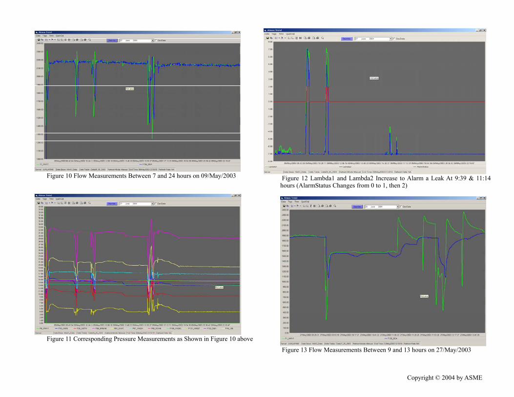
Figure 10 Flow Measurements Between 7 and 24 hours on 09/May/2003 ours (AlarmStatus Changes from 0 to 1, then 2)
Figure 12 Lambda1 and Lambda2 Increase to Alarm a Leak At 9:39 & 11:14
Figure 11 Corresponding Pressure Measurements as Shown in Figure 10 above
h
Figure 13 Flow Measurements Between 9 and 13 hours on 27/May/2003
Copyright © 2004 by ASME

Figure 14 Corresponding Pressure Measurements as Shown in Figure 13 above
Figure 15 Lambda1 and Lambda2 Increase to Alarm a Leak At 10:21, 11:08 & 1:59 hours (AlarmStatus Changes from 0 to 1, then 2)
(light green noisy line, the start of the trend, it
Figure 16 Flow Measurements and the Corresponding Flow Difference Under
1
Steady-State Operating Conditions. Flow Difference cale on right hand axis) started at around –10 m3/h at s
decreased to –20 when there was a small change in the flow-rate probably due to tank change. When the delivery changed from ROS (magenta line) to DEA (blue line), the flow difference increased from –20 to +10 m3/h, and it decreased slightly during this transfer. When the delivery switched back to ROS, the flow difference went back to –20 m3/h and it increased slightly before the end of the trend.
Copyright © 2004 by ASME