Transient Analysis of Electric Power System in … Analysis of Electric Power System in Refinery...
5
International Journal of Scientific & Engineering Research, Volume 7, Issue 4, April-2016 87 ISSN 2229-5518 IJSER © 2016 http://www.ijser.org Transient Analysis of Electric Power System in Refinery Industry: Case Study in PT. KIAS Gresik Eko Nugroho, T. Haryono, Suharyanto Abstract— Power quality of electric power system is a set of problems in industry which is necessary to be investigated. Dominating inductive load causes quality of the power factor decreasing. To improve power factor is obtained by installing a capacitor bank units. However, the existence of the capacitor causes other problems in power system. Analysis and simulation of electromagnetic transient is the basic methodology for understanding the performance of the power system, determining the level of reliability of electrical equipment, explaining the failure of equipment or testing of electrical equipment protection. Transient phenomenon in power systems related to the disturbance is caused by operating errors, the process of switching, lightning or load variations. This research is focusing in analyzing transient in PT. Alam Indah Karya Sejahtera (KIAS) Gresik, a refinery factory of palm oil processing. Transient analysis of the power system has not been done yet before. Therefore, transient analysis and simulation of the PT. KIAS Gresik power system is very important in this research. Transient simulation was done by software EMTP (electromagnetic transient program). From the analysis and simulation it was showed that biggest contributor transient overvoltage was the induction motor switching operation reaching 2251 V. To reduce the overvoltage, added a surge arrester could cut voltage to 400 V. Index Terms— EMTP, industry, overvoltage, protection, surge arrester, switching, transient. —————————— —————————— 1 INTRODUCTION ransient analysis is very important in manufacturing industrial system model which is steady-state or balanced is not reached. Transients in power system can be caused by normal and abnormal operations such as switching capacitors, switching circuit breaker, lightning, or a system with fluctuating workloads and other disturbances in the system [1]. Transient become very important because at the time a sudden change will be manifested in the form of current or voltage. In extreme conditions will cause damage to the system such as machine shutdown, disconnecting of electricity, disconnecting of communication systems, and others. Transients will not reach 2 p.u. in primary distribution system. However, the load close to the capacitor is increase the transient over voltage at the end of the rail to customers at low voltage capacitors. This indication will generate transient overvoltage up to 3-4 pu [2]. Transient will be damped when passing through the resistive part of a system. It is important reduce the voltage and current below the maximum operating limit of power system equipment and electrical machinery equipment. PT. Karya Indah Alam Sejahtera (KIAS) Gresik is a palm oil refinery industry was established in 2010 and started production in 2012. Transient analysis has not been done yet. The power system is still frequent disturbances, errors, malfunctions in production process and damage the electrical equipment. Analysis of the harmonics of the power system has been carried out and the results of the analysis showed good harmonic boundary with THD value 4, but electric power system transient analysis has not been done because of the limitation tools to analyse transient event. Therefore, this study will do a transient analysis of electric power systems for possibility occur of transient and these cause. The result of analysis are used as reference to explore opportunities for improvement as a recommendation to achieve a good power system and reliable so that the entire production process could run continuously. 2 SWITCHING OVERVOLTAGE OVERVIEW Switching surge is one type of voltage disturbances over highly affect the transmission and distribution systems. Circuited surge occurred due to opening and closing the breaker equipment interruption or CB (circuit breaker). Each installation of electrical circuits, both low voltage and high voltage must be equipped with device that is able to disconnect and reconnect the electrical installation called CB (circuit breaker). Other, the CB can also break the short circuit current during the disturbance, overcurrent and overvoltage protection. According to the CB functions will frequently open and close when the circuit power system disorders. The most feared of the transmission and distribution line is if the transformer suddenly turned on, means the CB will close and if the transformer is turned off, the CB will come open. Turning on the transformer suddenly will cause greater line stress and can cause traveling wave in a long time, while opening and closing the CB is probably over and over again. Traveling wave caused by CB operation is also called switching surge. In the switching process, transients will occur if a system switch is opening and closing. Temporary suspension by the switching operation in an electrical circuit which has the burden of inductances and capacitance will cause a transient T ———————————————— • Eko Nugroho is currently pursuing masters degree program in electric power engineering in Gadjah Mada University, Indonesia, PH-+6285643290219. E-mail: [email protected] • T. Haryono is a lecturer in masters degree program in electric power engineering in Gadjah Mada University, Indonesia. E-mail: [email protected] • Suharyanto is a lecturer in masters degree program in electric power engineering in Gadjah Mada University, Indonesia. E-mail: [email protected] IJSER
Transcript of Transient Analysis of Electric Power System in … Analysis of Electric Power System in Refinery...
International Journal of Scientific & Engineering Research, Volume 7, Issue 4, April-2016 87 ISSN 2229-5518
IJSER © 2016 http://www.ijser.org
Transient Analysis of Electric Power System in Refinery Industry: Case Study in PT. KIAS Gresik
Eko Nugroho, T. Haryono, Suharyanto
Abstract— Power quality of electric power system is a set of problems in industry which is necessary to be investigated. Dominating inductive load causes quality of the power factor decreasing. To improve power factor is obtained by installing a capacitor bank units. However, the existence of the capacitor causes other problems in power system. Analysis and simulation of electromagnetic transient is the basic methodology for understanding the performance of the power system, determining the level of reliability of electrical equipment, explaining the failure of equipment or testing of electrical equipment protection. Transient phenomenon in power systems related to the disturbance is caused by operating errors, the process of switching, lightning or load variations. This research is focusing in analyzing transient in PT. Alam Indah Karya Sejahtera (KIAS) Gresik, a refinery factory of palm oil processing. Transient analysis of the power system has not been done yet before. Therefore, transient analysis and simulation of the PT. KIAS Gresik power system is very important in this research. Transient simulation was done by software EMTP (electromagnetic transient program). From the analysis and simulation it was showed that biggest contributor transient overvoltage was the induction motor switching operation reaching 2251 V. To reduce the overvoltage, added a surge arrester could cut voltage to 400 V.
Index Terms— EMTP, industry, overvoltage, protection, surge arrester, switching, transient.
—————————— ——————————
1 INTRODUCTIONransient analysis is very important in manufacturing industrial system model which is steady-state or balanced is not reached. Transients in power system can be caused
by normal and abnormal operations such as switching capacitors, switching circuit breaker, lightning, or a system with fluctuating workloads and other disturbances in the system [1]. Transient become very important because at the time a sudden change will be manifested in the form of current or voltage. In extreme conditions will cause damage to the system such as machine shutdown, disconnecting of electricity, disconnecting of communication systems, and others.
Transients will not reach 2 p.u. in primary distribution system. However, the load close to the capacitor is increase the transient over voltage at the end of the rail to customers at low voltage capacitors. This indication will generate transient overvoltage up to 3-4 pu [2]. Transient will be damped when passing through the resistive part of a system. It is important reduce the voltage and current below the maximum operating limit of power system equipment and electrical machinery equipment.
PT. Karya Indah Alam Sejahtera (KIAS) Gresik is a palm oil refinery industry was established in 2010 and started production in 2012. Transient analysis has not been done yet. The power system is still frequent disturbances, errors, malfunctions in production process and damage the electrical equipment. Analysis of the harmonics of the power system has
been carried out and the results of the analysis showed good harmonic boundary with THD value 4, but electric power system transient analysis has not been done because of the limitation tools to analyse transient event. Therefore, this study will do a transient analysis of electric power systems for possibility occur of transient and these cause. The result of analysis are used as reference to explore opportunities for improvement as a recommendation to achieve a good power system and reliable so that the entire production process could run continuously.
2 SWITCHING OVERVOLTAGE OVERVIEW Switching surge is one type of voltage disturbances over
highly affect the transmission and distribution systems. Circuited surge occurred due to opening and closing the breaker equipment interruption or CB (circuit breaker).
Each installation of electrical circuits, both low voltage and high voltage must be equipped with device that is able to disconnect and reconnect the electrical installation called CB (circuit breaker). Other, the CB can also break the short circuit current during the disturbance, overcurrent and overvoltage protection. According to the CB functions will frequently open and close when the circuit power system disorders. The most feared of the transmission and distribution line is if the transformer suddenly turned on, means the CB will close and if the transformer is turned off, the CB will come open.
Turning on the transformer suddenly will cause greater line stress and can cause traveling wave in a long time, while opening and closing the CB is probably over and over again. Traveling wave caused by CB operation is also called switching surge.
In the switching process, transients will occur if a system switch is opening and closing. Temporary suspension by the switching operation in an electrical circuit which has the burden of inductances and capacitance will cause a transient
T
———————————————— • Eko Nugroho is currently pursuing masters degree program in electric power
engineering in Gadjah Mada University, Indonesia, PH-+6285643290219. E-mail: [email protected]
• T. Haryono is a lecturer in masters degree program in electric power engineering in Gadjah Mada University, Indonesia. E-mail: [email protected]
• Suharyanto is a lecturer in masters degree program in electric power engineering in Gadjah Mada University, Indonesia. E-mail: [email protected]
IJSER

International Journal of Scientific & Engineering Research, Volume 7, Issue 4, April-2016 88 ISSN 2229-5518
IJSER © 2016 http://www.ijser.org
oscillation. This condition causes more stress on the system. Switching surge with a very high increase may produce a spark jumps repetitive (arching) between the CB contacts, because of the excessive workload may result damage the CB.
Seen from Figure 1 which is described capacitor currents that preceded the (leading) voltage 90°. When the CB separated from the system, sparks will occur between the contacts CB then the current will continue to flow.
When the current reach the zero base value, sparks conductivity losses will interrupt. From Figure 1 Cs states the deviate of capacitance (stray capacitance). Arc suppressed indirect because the voltage VB which cut off CB contact where the value is equal to VS - VC too small. Hence, the capacitor remains charged with a voltage equal to the peak value of the supply voltage, i.e. 1 pu, or in other words voltage trapped on the capacitor is 1 pu. When the voltage polarity reversed, VB on CB will rise. Currently, VS has been changed to 1 pu in the cycle, there is a voltage cut off CB contact ± 2 pu. If the CB has get back the dielectric strength to withstand this voltage, the switching operation will be successful, otherwise it will penetrate between the insulator and the CB contact will be a short circuit.
Fig. 1. Transient overvoltage caused opening CB contact.
2.1 Capacitor Switching Capacitor bank was installed to provide reactive power in
order to resolve system voltage drop due to induction load, e.g. induction motor. In this case, capacitor switching causes the transient overvoltage. Some factor that affect the transient overvoltage gain during the switching capacitor process is the size of capacitor bank, short circuit capacity of the location where capacitor stored, power of transformer and load characteristic. Oscillation phenomenon of the switching capacitor transient is result of inductive and capacitive energy exchange element. Stored energy in capacitor element flows to the inductive element and oscillation transient occur during switching process.
Generally, transient will not reach 2 p.u. in primary distribution system, but in low voltage system which load near the capacitor, transient will reach 3-4 p.u. Figure 2 shown transient overvoltage that observed in upstream network where overshoot reach 1.34 pu.
2.2 Switching Transient of Induction Motor There was a large surge when the motor start which 5-7
times of nominal current that occurs in a short time and
resulting voltage transient. Generally, there are 3 method to minimize this, direct-on-line starting, star-delta starting, and autotrafo starting. This starting method is use to maintain voltage and current input. Transient in starting induction motor shown in Figure 3.
Fig. 2. Transient overvoltage caused opening CB contact.
Fig. 3. Transient overvoltage caused induction motor switching.
2.3 Standard Overvoltage Transient Level Connected equipment must have overvoltage transients
withstand. It’s equipment must have initial impulse voltage not smaller than the voltage level that applicable in the place of installation, as shown in Table 1.
TABLE 1 STANDARD MAXIMUM OVERVOLTAGE LEVEL
IJSER

International Journal of Scientific & Engineering Research, Volume 7, Issue 4, April-2016 89 ISSN 2229-5518
IJSER © 2016 http://www.ijser.org
PLN 20 kV CB2V VCB1 V
CB10
CB9
H L
CB6 P5613D1IM
I
I
CB8 P501 1/2IM
I
CB3
CB4
CB5
CB7 P5613D2IM
I
TR1P1 P2 P3
3 EMTP SIMULATION As a manufacturing company engaged in palm oil
processing, PT. KIAS Gresik is consists of two main processing unit, refinery and fractionation. To meet electric energy needs in production process, electrical power supplied from PLN as a primary source and generator as a backup source.
The amount of existing power is 2500 kVA which step-down by a transformer from 20 kV to 380 Volt L-L. Power is distributed to the production machines and lighting throughout the plant through the main panel MDP (main distribution panel) and SDP (sub distribution panels). For power factor correction 12 capacitors banks 125 kVar are installed, as shown in Figure 4.
For this analysis, electrical load are classified in lighting, induction motor and capacitor bank as shown in Figure 4. Simulation done with some cases of load switching. The observation point is located at P3.
Fig. 4. One line diagram power system in PT. KIAS Gresik.
4 RESULT AND DISCUSSION 4.1 Experiment Result
According to SNI 04-0225-200 standard protection equipment against overvoltage transients in equipment that works with a nominal voltage of 220/380 V is allowed to category 1. That is equipment in electronic circuits with a maximum voltage is 1500 Volt. In this chapter will explain EMTP simulation with load switching cases variated. This experiment focused switching operation when CB close and open in 0° and 90° sinusoidal sine. The 0° is determine zero crossing of sinusoidal sine and 90° is determine maximum amplitude of sinusoidal sine. Overvoltage reaching maximum value if CB contact close or open in 90° sinusoidal sine.
Fig. 5. Overvoltage transient when CB9 close at t = 0.025 s. Fig. 6(a). Overvoltage transient when CB6 close at t = 0.025 s.
Fig. 6(b). Overvoltage transient in Y-Δ starting of induction motor. Fig. 7. Overvoltage transient when CB3 close at t = 0.02 s and CB9 close
at t = 0.08 s.
Fig. 8. Overvoltage transien when CB6 close at t = 0.02 s and CB9 close
at t = 0.14 s.
IJSER
International Journal of Scientific & Engineering Research, Volume 7, Issue 4, April-2016 90 ISSN 2229-5518
IJSER © 2016 http://www.ijser.org
PLN 20 kV CB2V VCB1 V
CB10
CB9
H L
CB6 P5613D1IM
I
I
CB8 P501 1/2IM
I
CB3
CB4
CB5
CB7 P5613D2IM
I
TR1P1 P2 P3
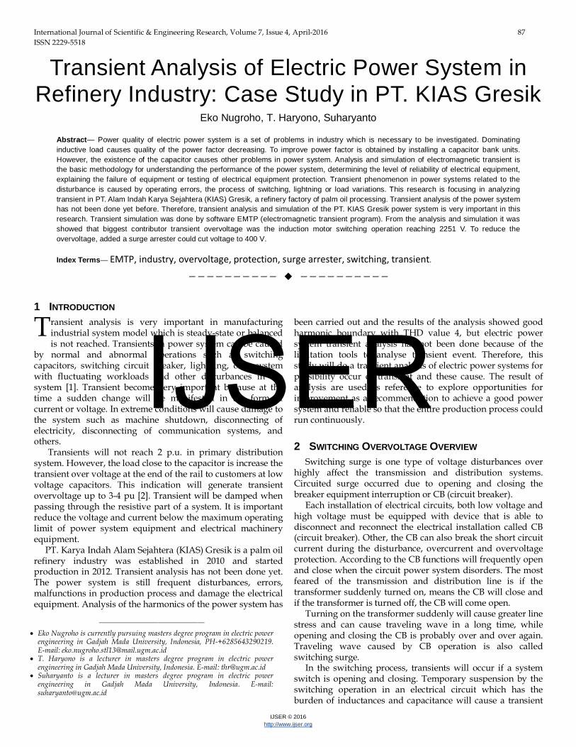
Fig. 9. Overvoltage transient in P3 when CB3 close at t = 0.02 s, CB6 close at t = 0.04 s and CB9 close t = 0.1 s.
Figure 5 is sinus voltage that observed in P3 during the
switching operation of CB9 switching with capacitor bank load. When CB9 close (on) at t = 0.2 s show the maximum voltage is 731 V and CB9 close (on) at t = 0.205 s is 758 V.
Figure 6(a) and 6(b) show the switching operation with a load circulation cooling water pump (P5613D1) with an induction motor that has a power of 90 kW. Switching operation of the motor is using Y-Δ starting method. When CB6 closed, CBY connected (on) and CBΔ open (off) and then after a delay time of 0.08 seconds CBY open (off) and CBΔ connected (on). When CBY connected, there is no overvoltage transient, but in case switching transfer to CBY-Δ there is a large transient overvoltage with maximum voltage is 2251 V. The voltage is reaching 2251 V during the switching transition which CBΔ open at 90° as shown in Figure 6(b).
Figure 7 show the switching operation of CB3 and CB9 interchangeably. When CB3 closed (on) at t = 0.02 s and CB9 closed at t = 0.08 s result maximum voltage of 730 V.
Figure 8 show the switching operation of CB6 and CB9 interchangeably. When CB6 closed (on) at t = 0.02 s and CB9 closed at t = 0.14 s result maximum voltage of 707 V.
Figure 9 show the switching operation of CB3, CB6 and CB9 interchangeably. When CB3 closed (on) at t = 0.02 s, CB6 at t = 0.04 s and CB9 at t = 0.1 s result maximum voltage of 700 V.
From the experiment above show the most problem in transient overvoltage appear when the switching operation occur in phase 90°. In this case, switching operation can not controlled in phase 0° because of the device tools limitation. Solution for this case is explained in the next chapter.
4.1 Experiment Result
Transient overvoltage can causes problems both production and equipment process, increasing cost production and decrease production yield. Transient overvoltage can not be avoided in PT. KIAS with fluctuating load characteristic, but it can be avoided by installing a surge arrester.
Surge arrester is protective devices in electrical system that restrict the overvoltage. If there is a transient overvoltage that goes into a power system that exceeds the limits of the voltage arresters will be deflected and discharged to the grounding. Thus the surge arrester will provide security for electronic equipment due to overvoltage transients which resulting from switching operations or lightning. Surge arrester installed in parallel with power system as shown in Figure 10.
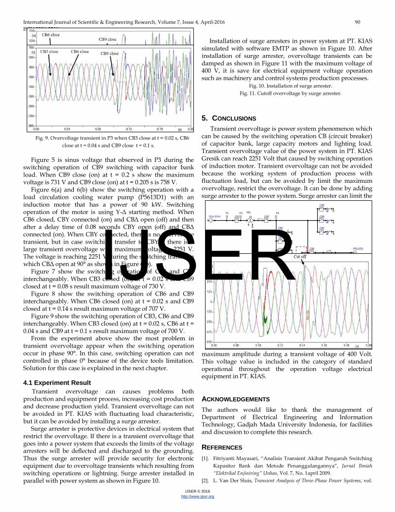
Installation of surge arresters in power system at PT. KIAS simulated with software EMTP as shown in Figure 10. After installation of surge arrester, overvoltage transients can be damped as shown in Figure 11 with the maximum voltage of 400 V, it is save for electrical equipment voltage operation such as machinery and control systems production processes.
Fig. 10. Installation of surge arrester. Fig. 11. Cutoff overvoltage by surge arrester.
5. CONCLUSIONS Transient overvoltage is power system phenomenon which
can be caused by the switching operation CB (circuit breaker) of capacitor bank, large capacity motors and lighting load. Transient overvoltage value of the power system in PT. KIAS Gresik can reach 2251 Volt that caused by switching operation of induction motor. Transient overvoltage can not be avoided because the working system of production process with fluctuation load, but can be avoided by limit the maximum overvoltage, restrict the overvoltage. It can be done by adding surge arrester to the power system. Surge arrester can limit the
maximum amplitude during a transient voltage of 400 Volt. This voltage value is included in the category of standard operational throughout the operation voltage electrical equipment in PT. KIAS.
ACKNOWLEDGEMENTS The authors would like to thank the management of Department of Electrical Engineering and Information Technology, Gadjah Mada University Indonesia, for facilities and discussion to complete this research.
REFERENCES [1]. Fitriyanti Mayasari, “Analisis Transient Akibat Pengaruh Switching
Kapasitor Bank dan Metode Penanggulangannya”, Jurnal Ilmiah “Elektrikal Enjiniring” Unhas, Vol. 7, No. 1april 2009.
[2]. L. Van Der Sluis, Transient Analysis of Three-Phase Power Systems, vol.
IJSER

International Journal of Scientific & Engineering Research, Volume 7, Issue 4, April-2016 91 ISSN 2229-5518
IJSER © 2016 http://www.ijser.org
6. 2001. [3]. G. Gopakumar, H. Yan, B. a Mork, and K. K. Mustaphi, “Shunt
Capacitor Bank Switching Transients : a Tutorial and Case Study,” Minnesota Power Syst. Conf., pp. 2–4, 1999.
[4]. C. Hwang and J. N. Lou, “Transient analysis of capacitance switching for industrial power system by PSpice,” Electr. Power Syst. Res., vol. 45, no. November 1997, pp. 29–38, 1998.
[5]. M. F. McGranaghan, D. R. Mueller, and M. J. Samotyj, “Voltage sags in industrial systems,” IEEE Trans. Ind. Appl., vol. 29, no. 2, pp. 397–403, 1993.
[6]. M. Ghaseminezhad, A. Doroudi, and S. H. Hosseinian, “A Novel Equivalent Circuit for Induction Motors under Voltage Fluctuation Conditions,” no. 1, pp. 53–61, 2012.
[7]. A. Shendge and N. Nagaoka, “EMTP Induction Motor Model from Modal Measurements for Inverter Surge Analysis,” vol. 2013, no. January, pp. 16–19, 2013.
[8]. F. Waskito and C. Banmongkol, “Simulation of the voltage sag effects on an induction motor,” 2011 Int. Conf. Consum. Electron. Commun. Networks, CECNet 2011 - Proc., pp. 731–734, 2011.
[9]. E. H. Camm, “Shunt Capacitor Overvoltages and a Reduction Technique,” 1999.
[10]. H. Tjahjono, “Sistem pengendali arus start motor induksi phasa tiga dengan variasi beban,” vol. 1, no. 2, pp. 1–5, 2012.
[11]. S. Rusnok, P. Sobota, V. Mach, P. Ka, and S. Mišák, “Possibilities of Program EMTP – ATP to Analyze the Starting Current of Induction Motor in Frequent Switching,” vol. 00, no. 8, pp. 1–6, 2015.
[12]. User Guide, “ETAP PowerStation 4.0,” no. 949, pp. 0–58, 2001. [13]. Nuri Haryati dan Mirna Nuriana Haryanto, “Fenomena Transien
Pada Starting Motor Induksi”, available: https://www.academia.edu
IJSER