Transformers
20
Transformers Workshop on Basic Electrical Engineering held at VVCE, Mysuru, on 30-April-2016 R S Ananda Murthy Associate Professor Department of Electrical & Electronics Engineering, Sri Jayachamarajendra College of Engineering, Mysore 570 006 R S Ananda Murthy Transformers
-
Upload
rsamurti -
Category
Engineering
-
view
134 -
download
1
Transcript of Transformers

TransformersWorkshop on Basic Electrical Engineering held at
VVCE, Mysuru, on 30-April-2016
R S Ananda Murthy
Associate ProfessorDepartment of Electrical & Electronics Engineering,
Sri Jayachamarajendra College of Engineering,Mysore 570 006
R S Ananda Murthy Transformers

Learning Outcomes
After completing this lecture the student should be able to –State why transformers are necessary in power systems.Describe the principle of operation of transformers.Describe the construction of core and shell types ofsingle-phase transformers.Calculate the induced E.M.F. in a transformer.Define voltage regulation of a transformer.Describe various power losses in a transformer.Find the efficiency of a transformer.
R S Ananda Murthy Transformers

Photograph of a Power Transformer
Power transformers are used at transmission level.
R S Ananda Murthy Transformers

Photograph of a Distribution Transformer
R S Ananda Murthy Transformers

Necessity of Transformers in Power Systems
Transformers are necessary to step up from generationvoltage which is typically 11 kV to transmission voltagelevels which are typically 220 kV or 400 kV.They are also required to step down voltage fromtransmission levels which are typically 220 kV or 400 kV todistribution levels which are typically 11 kV, 415 V(three-phase) or 230 V (single-phase).
R S Ananda Murthy Transformers

Core and Shell Types
Core TypeCross-section of core type transformer
L.V. Winding H.V. Winding
L.V. Winding H.V. Winding
Shell Type Cross-section of shell type transformer.
Cor
e
Yoke
Yoke
Cor
e
Laminations
Yoke
Yoke
Cor
e
Cor
e
Cor
e
Laminations
R S Ananda Murthy Transformers

Core Type Transformer
R S Ananda Murthy Transformers

Shell Type Transformer
R S Ananda Murthy Transformers

Principle of Operation of Transformer
Load
When supply is given to the primary winding having T1 turns,an alternating flux is established in the transformer core. Due tothis, there will be change of flux linkage in the primary and alsoin the secondary winding. Then, according to Faraday’s law,voltage is induced in both the primary and secondary windings.
R S Ananda Murthy Transformers

Induced E.M.F. in Transformer
When the primary applied voltage is sinusoidal, the mutual fluxφ also varies sinusoidally. So, let
φ = Φmax sinωt (1)
where ω = 2πf and f = supply frequency. Let the flux linkage ofthe primary and secondary be
λ1 = φT1 and λ2 = φT2 (2)
According to Faraday’s law, when φ changes, voltage isinduced in both primary and secondary. The voltage induced inthe primary is given by
e1 =−dλ1
dt=−T1
ddt
(Φmax sinωt) = ωT1Φmax sin(ωt−90◦) (3)
R S Ananda Murthy Transformers
Induced E.M.F. in Transformer
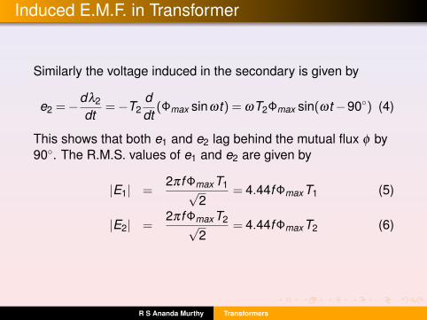
Similarly the voltage induced in the secondary is given by
e2 =−dλ2
dt=−T2
ddt
(Φmax sinωt) = ωT2Φmax sin(ωt−90◦) (4)
This shows that both e1 and e2 lag behind the mutual flux φ by90◦. The R.M.S. values of e1 and e2 are given by
|E1| =2πf ΦmaxT1√
2= 4.44f ΦmaxT1 (5)
|E2| =2πf ΦmaxT2√
2= 4.44f ΦmaxT2 (6)
R S Ananda Murthy Transformers

Voltage Transformation Ratio
In a practical transformer, the voltage drop in primary andsecondary winding impedances is very small — typically lessthan 5% of the rated voltage. So, by applying K.V.L. to theprimary and secondary we get
V1 ≈ E1 and V2 ≈ E2 (7)
Hence we can write
|V1||V2|
≈ |E1||E2|
=T1
T2= a12 (8)
This is known as voltage transformation ratio.
R S Ananda Murthy Transformers

Current Transformation Ratio
Due to good magnetic material used for the core, it can beshown that the reluctance of the core is almost zero. Thismeans that
F1 = F2 =⇒ |F1|= T1|I1|= |F2|= T2|I2|
where F1 is the primary M.M.F. and F2 is the secondary M.M.F.Therefore,
|I1|T1 ≈ |I2|T2 =⇒ |I1||I2|
=T2
T1= a21 =
1a12
(9)
This shows that current transformation ratio is the reciprocal ofvoltage transformation ratio.
R S Ananda Murthy Transformers

Voltage Regulation
Voltage regulation of a transformer is defined as
Regulation =|V2NL|− |V2FL||V2FL|
×100%
where V2NL = secondary terminal voltage when there is noload, V2FL = secondary terminal voltage when there is fullload.Ideally the regulation should be zero which means that thesecondary terminal voltage should not vary from no-load tofull-load.Typically the regulation of practical transformers would beless than 5%.
R S Ananda Murthy Transformers

Power Losses in Transformer
Copper Loss (Pcu) in primary and secondary windings.Iron Loss (Pi) which has two components
Hysteresis loss Ph = khtfB1.6max
Eddy current loss Pe = kef 2t2B2max
where Pe = eddy current loss, Ph = hysteresis loss, t =thickness of laminations used in the core. kh = hysteresis lossconstant, and ke =eddy current loss constant which areconstants for a particular material used for the core.Bmax = Φmax/Ai is the maximum flux density of in the core.
This shows that by using very thin laminations, iron loss can bereduced and by using good conducting material like copper oraluminium for the windings, copper loss can be reduced.
R S Ananda Murthy Transformers

Copper Loss (Pcu)
This is nothing but I2R loss occurring in the primary andsecondary winding resistances. Since I2R power loss isproportional to square of current in the windings, it is obviousthat this power loss varies with load.
If Pcu(r) is the copper loss in the transformer at full-load current,then, at any multiple x of full load, the copper loss will bePcu = x2Pcu(r).
R S Ananda Murthy Transformers

Iron Loss (Pi)
Maximum value of flux in the transformer core is given by
Φmax ≈|V1|
4.44fT1(10)
Since the primary supply voltage |V1| and frequency f areconstant, Φmax will also be constant.The iron loss in a transformer is given by
Pi = Pe + Ph = kef 2t2B2max + khtfB1.6
max (11)
This shows that, at constant frequency and supply voltagethe iron loss Pi will remain practically constant even if theload varies.
R S Ananda Murthy Transformers

Efficiency of Transformer
The efficiency of transformer at any multiple x of full-load isgiven by
η =Pout
Pin=
x |V2r | · |I2r |cosθ
x |V2r | · |I2r |cosθ + Pi + x2Pcu(r)(12)
which is same as
η =x |Sr |cosθ
x |Sr |cosθ + Pi + x2Pcu(r)
where x = any multiple of full load, |Sr |= rated volt-amperes ofthe transformer, cosθ = power factor of the load, Pi = iron lossof the transformer which is constant, and Pcu(r) = copper loss inthe transformer at rated load.
R S Ananda Murthy Transformers

Condition for Maximum Efficiency
At maximum efficiency, dη/dx = 0. Applying this condition weget the condition for maximum efficiency as
Pi = x2Pcu(r) =⇒ x =
√Pi
Pcu(r)
This gives the multiple x of full load at which efficiency will bemaximum. In this equation, for full load we have to take x = 1,for half-load x = 0.5, for quarter load x = 0.25, and so on.
R S Ananda Murthy Transformers

License
This work is licensed under aCreative Commons Attribution 4.0 International License.
R S Ananda Murthy Transformers