Transformer Replacement Program - National Grid ... National Grid, Transformer Replacement Program...
32
Transformer Replacement Program for Low-Voltage Dry-Type Transformers Implementation Manual Version 2013.1 | April 4, 2013
Transcript of Transformer Replacement Program - National Grid ... National Grid, Transformer Replacement Program...
Transformer Replacement Program
for Low-Voltage Dry-Type Transformers Implementation Manual Version 2013.1 | April 4, 2013

Disclaimer: Please acquire and review the latest version of this document before submitting a project for an incentive pre-approval. Ongoing consultation with the National Grid program manager during development of the project is essential to maximize the chances for receiving an incentive. Circumstances may require additional requirements for the customer to receive an incentive.

National Grid, Transformer Replacement Program Implementation Manual i
Table of Contents
Purpose of this Guide ............................................................................................................................................ 2
Section 1. About Transformers .............................................................................................................................. 3
What is a transformer? ............................................................................................................................................. 3
Transformer Energy Consumption and Losses .......................................................................................................... 3
History of Transformer Energy Codes ....................................................................................................................... 5
Transformer Loading ................................................................................................................................................. 7
Energy Savings .......................................................................................................................................................... 9
Efficiency Improvements .......................................................................................................................................... 9
Transformer Life Expectancy ................................................................................................................................... 11
Measure Lifetimes for Transformer Replacement Projects ..................................................................................... 12
Section 2. Transformer Program Description ....................................................................................................... 14
Equipment Eligible for Funding ............................................................................................................................... 14
Transformer Downsizing ......................................................................................................................................... 15
Savings Calculations ................................................................................................................................................ 16
Qualifying Criteria ................................................................................................................................................... 17
Incentive Levels ....................................................................................................................................................... 17
Section 3. Transformer Program Application Process .......................................................................................... 18
Application Form ..................................................................................................................................................... 18
Post-Installation Inspection .................................................................................................................................... 19
Post-Installation Evaluation .................................................................................................................................... 20
Section 4. Transformer Savings Tool .................................................................................................................... 21
Worksheet Descriptions .......................................................................................................................................... 22
Required Inputs ....................................................................................................................................................... 23
Step-by-Step Instructions ........................................................................................................................................ 24
References ........................................................................................................................................................... 26
Attachment 1—Metering Transformers ............................................................................................................... 27
Metering Challenges ............................................................................................................................................... 27
Basic Metering Requirements ................................................................................................................................. 27
Harmonic Considerations ........................................................................................................................................ 28
Characteristics of Commonly Used Meters ............................................................................................................. 28
Meters and Power Harmonics .............................................................................................................................. 30

National Grid, Transformer Replacement Program Implementation Manual 2
Purpose of this Guide National Grid provides incentives to commercial and industrial customers for early replacement of low-voltage dry-type transformers with transformers that meet or exceed the current TP-1 standard. This guide provides the background information and guidelines for identifying, qualifying, and submitting applications for transformer replacement projects. The replacement of failed transformers does not qualify for incentives. Section 1 provides background information about transformers and key terms used in this guide. Section 2 describes the incentive program available to commercial, industrial, and municipal electric customers, including equipment and project eligibility requirements. Section 3 describes the application process for submitting a transformer replacement project and receiving the program incentive. Section 4 describes how to identify eligible transformers for replacement, and the process for: collecting the required inputs, specifying replacement transformers, and determining whether the project qualifies for an incentive. It also contains a user manual for the Transformer Replacement Calculation Tool, which must be used to estimate peak demand and energy savings for the application process. Program Manager Contact the program manager with questions about the program, incentives, or access to the Transformer Savings Tool (TST). Name Dinesh Patel Phone 781-907-2250 Email [email protected]

National Grid, Transformer Replacement Program Implementation Manual 3
Section 1. About Transformers This section provides information about low-voltage dry-type distribution transformers, including:
• Descriptions of transformer energy consumption and losses; • Transformer efficiency and energy codes; • Typical loading profiles; and • Expected equipment lifetimes.
What is a transformer? Transformers pass alternating current electricity, and normally are used to step voltage up or down. This specification focuses on is low-voltage dry-type transformers used in commercial, industrial, and municipal facilities to transform 408/277 volt power to 208/120 power used for equipment or plug-loads within buildings. These transformer sizes range from 15 kVA to 750 kVA, with most transformers in the 45 kVA and 75 kVA size categories. Commercial and industrial facilities served by three-phase power from a utility typically use low-voltage dry-type transformers to distribute power internally at 208/120 Volts. Loads commonly served by such transformers include: wall plugs, lights, fans, and equipment such as computers, printers, and small industrial machinery. Figure 1 shows a typical low-voltage dry-type transformer and Figure 2 shows a sample transformer nameplate. The transformer nameplate provides information about the transformer type (dry type), size (150 kVA), and rated temperature rise (150 deg. C).
Figure 1. Low-voltage Dry-type Transformer Figure 2. Nameplate for Existing Transformer
Transformer Energy Consumption and Losses Transformer designs seek to transform power and energy rather than consume it. A perfect transformer provides useful output power equal to the input power. In reality, the transformation process is not 100% efficient and some power and energy is lost through waste heat and vibration. The total transformer loss is the difference between the input power and the useful output power.
National Grid, Transformer Replacement Program Implementation Manual 4
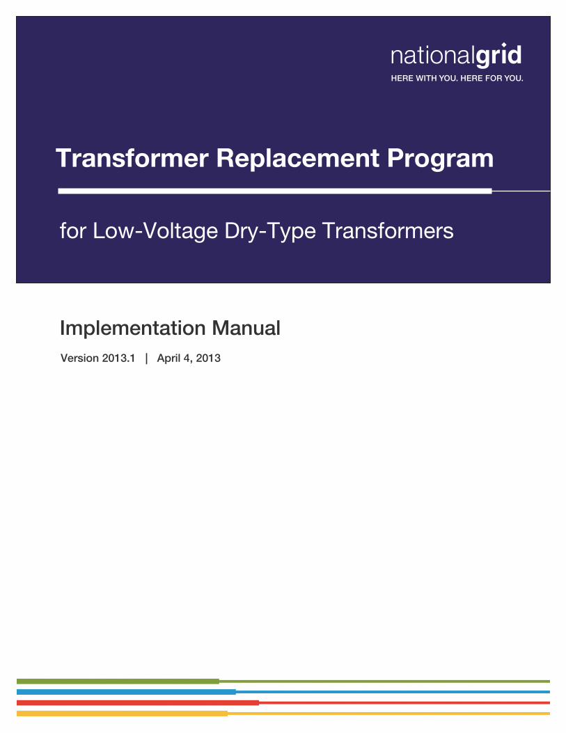
Transformers lose energy through two pathways:
• Core Losses or No-Load Losses (NLL). Core losses, often referred to as NLL, remain relatively constant, and do not vary with the load.
• Winding Losses or Full Load Losses (FLL). Winding losses, normally expressed as FLL, arise from current traveling through a transformer’s coils, and vary with the square of the load.
Table 1 shows typical total energy losses at various load, three-phase, low voltage dry-type transformers, manufactured prior to the TP-1 standard. The table shows the NLL and FLL values and the total energy waste in watts at various load factors.
Table 1. Expected Losses (Watts) for Pre-TP-1 Transformers
Figure 3 shows how expected transformer losses increase with loading.
Figure 3. Expected Losses for Pre TP-1 Transformers
0% 5% 10% 15% 20% 25% 30% 35% 40% 45% 50% 55% 60% 65% 70% 75% 80% 85% 90% 95% 100%15 162 712 200 200 200 200 200 200 200 200 300 300 300 300 400 400 500 500 600 700 700 800 90030 256 1,274 300 300 300 300 300 300 300 400 400 500 500 600 700 700 800 900 1,000 1,100 1,300 1,400 1,50045 322 1,655 300 300 300 400 400 400 400 500 500 600 700 800 800 900 1,100 1,200 1,300 1,500 1,600 1,800 2,00075 462 2,542 500 500 500 500 500 600 600 700 800 900 1,000 1,100 1,300 1,400 1,600 1,800 2,000 2,200 2,500 2,700 3,000
112.5 604 3,457 600 600 600 700 700 800 800 900 1,100 1,200 1,300 1,500 1,700 1,900 2,100 2,400 2,700 3,000 3,300 3,700 4,100150 661 4,690 700 700 700 700 800 900 1,000 1,100 1,300 1,500 1,700 1,900 2,100 2,400 2,800 3,100 3,500 3,900 4,400 4,800 5,400225 862 6,242 900 900 900 1,000 1,100 1,200 1,300 1,500 1,700 1,900 2,200 2,500 2,800 3,200 3,700 4,100 4,600 5,200 5,800 6,400 7,100300 1,087 7,397 1,100 1,100 1,100 1,200 1,300 1,400 1,600 1,800 2,100 2,300 2,700 3,000 3,400 3,900 4,400 4,900 5,500 6,200 6,900 7,700 8,500500 1,648 11,166 1,600 1,700 1,700 1,800 2,000 2,200 2,400 2,700 3,100 3,500 4,000 4,600 5,200 5,900 6,600 7,500 8,400 9,400 10,500 11,600 12,900750 2,189 14,830 2,200 2,200 2,300 2,400 2,600 2,900 3,200 3,600 4,100 4,700 5,300 6,100 6,900 7,800 8,800 9,900 11,100 12,500 13,900 15,400 17,100
1000 2,677 18,139 2,700 2,700 2,800 3,000 3,200 3,600 4,000 4,500 5,100 5,700 6,500 7,400 8,400 9,500 10,800 12,100 13,600 15,200 17,000 18,900 20,900
Size (kVA) NLL FLL Load Factor

National Grid, Transformer Replacement Program Implementation Manual 5
Figure 4 shows how the efficiency of pre TP-1 transformers varies with loading.
Figure 4. Typical Efficiency for Pre TP-1 Transformers
History of Transformer Energy Codes In 1996, the National Electrical Manufacturer’s Association (NEMA) established the TP-1 standard for transformer efficiency, which recommends efficiency requirements for various sizes of transformers. For dry-type transformers, these efficiency standards set minimum efficiency requirements for a 35% load fraction, at least 0.5% higher than standard transformers available at the time of the specification. Although a 0.5% rise in efficiency seems small, these transformers had operating efficiencies of roughly 97% to 98%, meaning losses of 2% to 3%. Improving the efficiency by 0.5% out of 2% results in cutting energy and power losses by 25%. Current Federal Standard1 In its rulemaking for a national standard, the U.S. adopted the NEMA TP-1 standard of 1996 and 2002. The standard states:
The efficiency of a low-voltage dry-type distribution transformer manufactured on or after January 1, 2007, shall be no less than that required for their kVA rating in the table below. Low-voltage dry-type distribution transformers with kVA ratings not appearing in the table shall have their minimum efficiency level determined by linear interpolation of the kVA and efficiency values immediately above and below that kVA rating.
1 http://www1.eere.energy.gov/buildings/appliance_standards/product.aspx/productid/66
National Grid, Transformer Replacement Program Implementation Manual 6
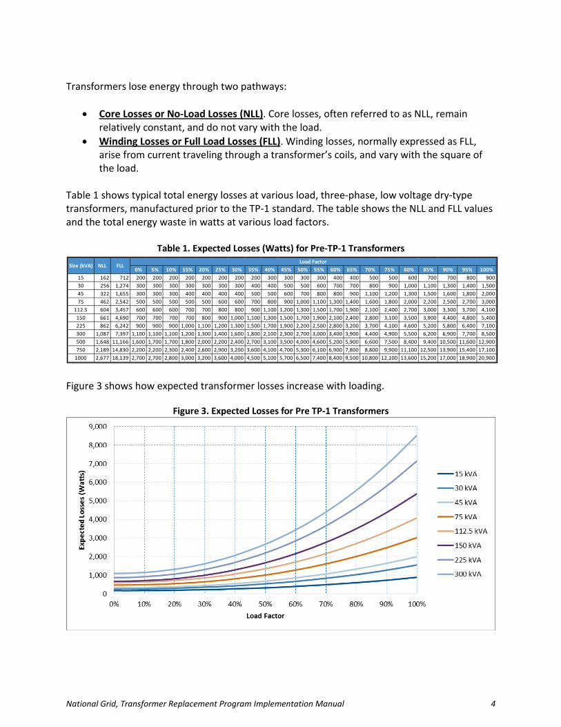
Table 2. Minimum Efficiency* Requirements for Low-Voltage Dry-Type Transformers
Single-phase Three-phase kVA Efficiency (%) kVA Efficiency (%) 15 97.7% 15 97.0% 25 98.0% 30 97.5% 37.5 98.2% 45 97.7% 50 98.3% 75 98.0% 75 98.5% 112.5 98.2% 100 98.6% 150 98.3% 167 98.7% 225 98.5% 250 98.8% 300 98.6% 333 98.9% 500 98.7% 750 98.8% 1000 98.9%
*Efficiencies are determined at the following reference conditions: (1) for NLLs, at the temperature of 20°C; and (2) for load-losses, at the temperature of 75°C, and 35% of nameplate load. (Source: Table 4–2 of NEMA Standard TP–1–2002, “Guide for Determining Energy Efficiency for Distribution Transformers.”)
NEMA Premium® Efficiency Transformer Program After the Federal government adopted the TP-1 standards in their rulemaking, NEMA developed the Premium® Efficiency Transformer program, which specifies the criteria to qualify low-voltage dry-type transformers as NEMA Premium® Compliant Transformers. The program applies to low-voltage dry-type transformers between 15 kVA and 333 kVA for single-phase units and between 15 kVA and 1000 kVA for three-phase units. To qualify as a NEMA Premium® Compliant Transformer, units must meet or exceed the nominal energy-efficiency levels presented in Table 3. NEMA Premium® Compliant Transformer specifications became effective in May 2010.

National Grid, Transformer Replacement Program Implementation Manual 7
Table 3. Minimum Efficiency Requirements* for NEMA Premium® Efficiency Transformers
Single-phase Three-phase kVA Efficiency (%) kVA Efficiency (%) 15 98.39% 15 97.90% 25 98.60% 30 98.25% 37.5 98.74% 45 98.39% 50 98.81% 75 98.60% 75 98.95% 112.5 98.74% 100 99.02% 150 98.81% 167 99.09% 225 98.95% 250 99.16% 300 99.02% 333 99.23% 500 99.09% 750 99.16% 1000 99.23%
*Efficiencies are determined at the following reference conditions: (1) for NLLs, at the temperature of 20°C; and (2) for load-losses, at the temperature of 75°C and 35% of nameplate load. (Source: Table 4–2 of NEMA Standard TP–1–2002, “Guide for Determining Energy Efficiency for Distribution Transformers.”)
Distribution transformers meeting the NEMA Premium® specification typically include the NEMA Premium® Mark on the equipment nameplate (shown in Figure 5).
Figure 5. NEMA Premium® Mark
Transformer Loading Many National Grid vendors and contractors have observed that most commercial distribution transformers are oversized. A 1999 study found low-voltage transformers in commercial and municipal facilities had average loading of 16% of the nameplate.2 Figure 6 shows the average load factor for transformers, per various building types, as measured during the same study. The data show that the typical transformer load is about half of the 35% load factor on which the TP-1 efficiency standards are based.
2 The Cadmus Group, Inc. 1999. Low-Voltage Transformer Loads in Commercial, Industrial, and Public Buildings. Prepared for Northeast Energy Efficiency Partnerships.

National Grid, Transformer Replacement Program Implementation Manual 8
Figure 6. Typical Average Transformer Loads by Building Type*
*The Cadmus Group, Inc. 1999. Low-Voltage Transformer Loads in Commercial, Industrial, and Public Buildings. Prepared for Northeast Energy Efficiency Partnerships.
Many transformers are oversized for the following reasons:
1. In commercial buildings, transformers sizes are specified based on power density tables in the electrical code and the number of receptacles, or on outdated lighting power density assumptions. In industrial applications, they are based on the nameplate of the connected loads, which engineers calculate using conservative values, allowing for future load growth (which often does not occur). When this happens for many pieces of equipment and loads throughout the building, the compounded oversizing effect makes the transformer sizing much larger than required by loads.
2. Transformer sizing often neglects or underestimates load diversity factors.
3. National Grid has conducted energy-efficiency programs for more than 20 years, thus
reducing loads on transformers. For example, lighting power densities have fallen from 1.5 watts/sq. ft. to less than 1.0 watts/sq. ft., resulting in a large reduction in the loading of transformers serving lighting loads. Lighting controls—such as occupancy controls, scheduling controls, daylight dimming, and others—have further reduced loads on existing transformers. Office equipment, including computers, printers, and monitors, has become more efficient. These devices also now go into sleep mode when not in use. Roughly five years ago, computers drew 80 watts, and CRT monitors drew 60 watts. Today’s desktop computers use roughly 45 watts, and LCD monitors use roughly 20 watts, while laptops use even less. Consequently, peak office plug loads have dropped by more than half, and, due to sleep functions, average loads have dropped even further.

National Grid, Transformer Replacement Program Implementation Manual 9
Figure 7 shows the average weekday (WD) and weekend (WE) load profile for a transformer in a commercial application.
Figure 7. Typical Transformer Load Profile3
Energy Savings Energy and demand savings can be achieved by replacing existing transformers with new transformers that are more efficient and by downsizing transformers to reduce the core losses.
Efficiency Improvements Energy-savings opportunities arise from the higher efficiency of new transformers, compared to those installed in facilities prior to that state’s or the Federal adoption of the TP-1 efficiency standard. Commonly sized transformers can produce efficiency gains of 1% and NLL savings of nearly 400 Watts. For example, a pre TP-1 225 kVA unit typically produced core losses of 860W, and the same size NEMA Premium® models produces core losses of about 480W. Based on 24/7 operations, replacing this pre-TP-1 transformer with the premium unit would save 3.3 MWh each year.4 Table 4 shows the expected annual kWh losses for a pre-TP-1 transformer, a TP-1 compliant transformer, and a NEMA Premium® transformer; and the expected annual kWh savings from replacing a typical pre-TP-1 transformer with a TP-1 compliant or NEMA Premium® transformer of the same size.
3 The typical load profile is based metered data for commercial transformers. 4 (860 Watts – 480 Watts) * 8760 hours/year / 1,000,000 Watts/MW
National Grid, Transformer Replacement Program Implementation Manual 10
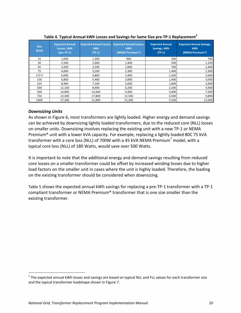
Table 4. Typical Annual kWh Losses and Savings for Same Size pre-TP-1 Replacement5
Downsizing Units As shown in Figure 6, most transformers are lightly loaded. Higher energy and demand savings can be achieved by downsizing lightly loaded transformers, due to the reduced core (NLL) losses on smaller units. Downsizing involves replacing the existing unit with a new TP-1 or NEMA Premium® unit with a lower kVA capacity. For example, replacing a lightly loaded 80C 75 kVA transformer with a core loss (NLL) of 700W with a 45 kVA NEMA Premium® model, with a typical core loss (NLL) of 180 Watts, would save over 500 Watts. It is important to note that the additional energy and demand savings resulting from reduced core losses on a smaller transformer could be offset by increased winding losses due to higher load factors on the smaller unit in cases where the unit is highly loaded. Therefore, the loading on the existing transformer should be considered when downsizing. Table 5 shows the expected annual kWh savings for replacing a pre-TP-1 transformer with a TP-1 compliant transformer or NEMA Premium® transformer that is one size smaller than the existing transformer.
5 The expected annual kWh losses and savings are based on typical NLL and FLL values for each transformer size and the typical transformer loadshape shown in Figure 7.
Size (kVA)
Expected Annual Losses, kWh
(pre-TP-1)
Expected Annual Losses, kWh
(TP-1)
Expected Annual Losses, kWh
(NEMA Premium®)
Expected Annual Savings, kWh
(TP-1)
Expected Annual Savings, kWh
(NEMA Premium®)
15 1,600 1,300 900 300 70030 2,500 2,000 1,400 500 1,10045 3,200 2,500 1,800 700 1,40075 4,600 3,200 2,300 1,400 2,300
112.5 6,000 4,800 3,400 1,200 2,600150 6,800 5,400 3,800 1,400 3,000225 8,900 7,100 5,000 1,800 3,900300 11,100 8,900 6,200 2,200 4,900500 16,800 13,400 9,400 3,400 7,400750 22,300 17,800 12,500 4,500 9,800
1000 27,300 21,800 15,300 5,500 12,000

National Grid, Transformer Replacement Program Implementation Manual 11
Table 5. Typical Annual kWh Savings for pre-TP-1 Replacement and Downsize6
The expected annual energy savings for a downsized replacement are typically higher than the expected annual energy savings for a same size replacement. However, for highly loaded units, the lower core losses (NLL) could be offset by the higher load levels (and therefore, higher winding losses) on the smaller transformer. Generally, the benefit from downsizing is the lower cost of the smaller transformer, rather than the increased savings, which improves the project cost-effectiveness and reduces the payback period.
Transformer Life Expectancy In typical use, transformers last more than 20 to 30 years, with a transformer’s life expectancy generally related to its average operating temperature (which is proportional to its average loading conditions). Most transformer designs operate at a 150 ºC temperature rise upon fully-loaded conditions, but do not operate at those fully loaded conditions continuously. Given light loads, most transformers never operate at maximum design conditions, and, in reality, run much cooler than conditions for which they were designed. Consequently, life expectancies can increase many times, and most transformers last much longer than 50 years. Electricians and building inspectors, which Cadmus contacted in writing this manual, stated they rarely see transformers fail, and almost never have to replace these devices. Figure 8 shows a curve of average transformer life versus loading, which Cadmus adapted from a Square D publication7 that predicted transformer life with temperature rises. The curve shows a transformer operated continuously at full capacity experiences a very short life, but continuous operation an average load of 50% lengthens its life to 75 years.
6 The expected annual kWh savings are based on typical NLL and FLL values for each transformer size and the typical transformer loadshape shown in Figure 7. The loadshape on the downsized 7 Power Logic Solutions. Volume 3, Issue 3. Square D Corporation. October 2003.
Original Size (kVA)
New Size(kVA)
Expected Annual Savings, kWh
(TP-1)
Expected Annual Savings, kWh
(NEMA Premium®)
15 N/A N/A N/A30 15 800 1,30045 30 900 1,60075 45 1,500 2,400
112.5 75 1,800 3,100150 112.5 1,500 3,100225 150 2,300 4,300300 225 3,100 5,500500 300 5,500 8,900750 500 6,000 10,900
1000 750 7,300 13,300

National Grid, Transformer Replacement Program Implementation Manual 12
Figure 8. Average Transformer Life vs. Fractional Loading
Source: Square D Life versus temperature data, converted to age versus load by Cadmus using full load and 35% load temperatures. In a study of 89 randomly selected transformers, Cadmus only found one transformer with a 60% load, and only four with a 40% to 50% load. The remaining 84 transformers operated at average loads less than 37%, and, averaged over all transformers, operated at load factors just 16% of the transformers’ nameplate capacity. Based on Cadmus’ findings, National Grid’s program estimates a conservative effective useful life (EUL) of 50 years for low-voltage dry-type transformers in nonresidential facilities.
Measure Lifetimes for Transformer Replacement Projects Energy-efficiency measures have a maximum allowable lifetime of 30 years; so measure savings can only be claimed for the first 30 years of a new transformer’s lifetime. Two components make up this 30-year period: (1) the remaining useful life (RUL) of the existing transformer; and (2) the additional lifetime of the new transformer, compared to a new code-compliant transformer. One calculates the RUL of an existing transformer as the difference between the EUL and the age of the existing transformer:
RUL = EUL – Age

National Grid, Transformer Replacement Program Implementation Manual 13
Energy and demand savings during this RUL period can be calculated by comparing the new transformer to the existing transformer. Given the maximum measure life of 30 years, the RUL can last no longer than 30 years. Energy and demand savings for any years following the RUL (up to 30 years) can be calculated by comparing the new transformer to a code-compliant transformer, as this period would be assumed to follow the EUL of an existing transformer. This period, the code baseline lifetime (CBL), can be calculated as the difference between the measure life and the RUL:
CBL = Measure Life – RUL Figure 9 shows how these two baselines—the existing transformer baseline and the code-compliant baseline—apply over the measure life for early-replacement transformer projects.
Figure 9. Dual Baseline over Transformer Replacement Measure Life
National Grid, Transformer Replacement Program Implementation Manual 14
Section 2. Transformer Program Description The National Grid transformer program provides incentives for early replacements of existing, inefficient distribution transformers with new transformers meeting or exceeding the minimum efficiency required by Federal Standards. The replacement of failed transformers does not qualify for incentives. This program focuses on the early replacement of low-voltage dry-type transformers in commercial, industrial, and municipal facilities, installed prior to state and Federal adoption of the TP-1 standard. These older transformers have much lower efficiencies, varying from 92% to 95% at rated load conditions, and even lower efficiencies at typical loading conditions. Due to economic reasons, customers often do not replace the transformers unless they fail in service; so many old transformers continue to operate in existing commercial and industrial facilities and have long RULs. If an existing transformer is lightly loaded, the replacement project may also include downsizing existing equipment (replacing the existing unit with a new, smaller unit). Downsizing the transformer may increase the project’s demand and energy savings by optimizing the unit’s operating efficiency, and may improve the project’s cost-effectiveness by reducing the project’s cost.
Equipment Eligible for Funding The existing transformer must be a low-voltage dry-type that does not meet the TP-1 efficiency standard. The age of the existing transformer can be compared to the state’s TP-1 adoption year (Table 6) to determine whether it is eligible for the Transformer Replacement Program:
• Transformers installed before the state’s TP-1 adoption date likely do not meet the TP-1 standard and qualify for replacement.
• Transformers installed after the state’s TP-1 adoption date most likely meet the TP-1 standard and do not qualify for replacement.
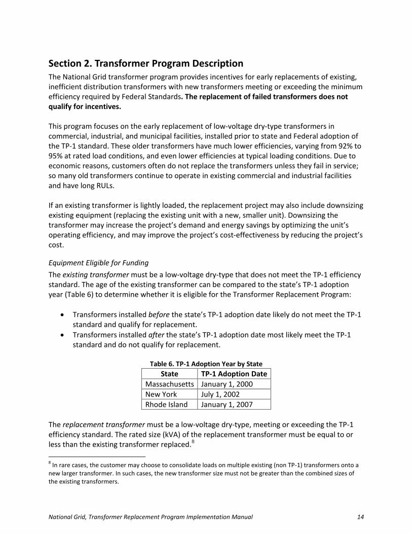
Table 6. TP-1 Adoption Year by State
State TP-1 Adoption Date Massachusetts January 1, 2000 New York July 1, 2002 Rhode Island January 1, 2007
The replacement transformer must be a low-voltage dry-type, meeting or exceeding the TP-1 efficiency standard. The rated size (kVA) of the replacement transformer must be equal to or less than the existing transformer replaced.8 8 In rare cases, the customer may choose to consolidate loads on multiple existing (non TP-1) transformers onto a new larger transformer. In such cases, the new transformer size must not be greater than the combined sizes of the existing transformers.
National Grid, Transformer Replacement Program Implementation Manual 15
Transformer Downsizing Most projects involve replacement of an existing, non-TP-1 transformer with a new transformer of the same size. As discussed previously, code requirements based on outdated load density assumptions lead to oversizing most transformers. Efficiency standards for equipment served by transformers (including lighting, computers, and other plug-in appliances) have greatly reduced loads served by transformers, resulting in many transformers operating outside of their peak efficiency ranges. Reducing the new transformer’s size can improve the unit’s operating efficiency, provide additional savings due to reduced losses, and make a transformer replacement project more cost–effective due to lower material costs for a smaller transformer. Downsizing transformers should only be considered upon meeting the following criteria:
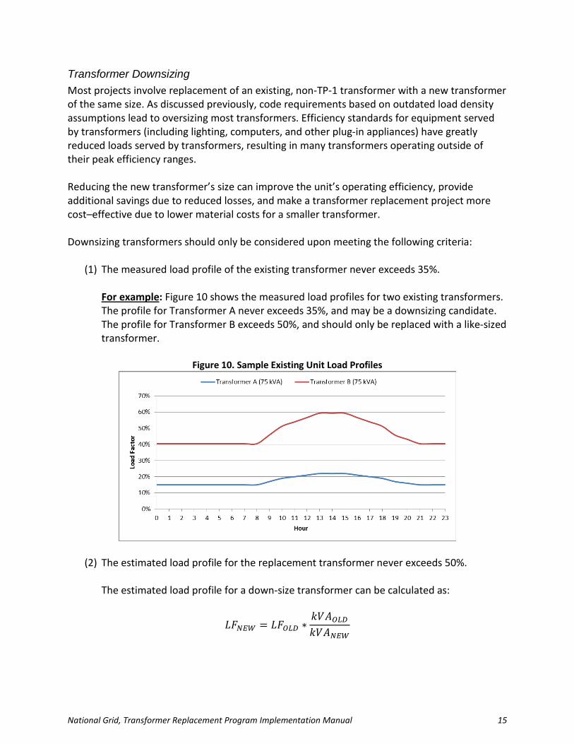
(1) The measured load profile of the existing transformer never exceeds 35%. For example: Figure 10 shows the measured load profiles for two existing transformers. The profile for Transformer A never exceeds 35%, and may be a downsizing candidate. The profile for Transformer B exceeds 50%, and should only be replaced with a like-sized transformer.
Figure 10. Sample Existing Unit Load Profiles
(2) The estimated load profile for the replacement transformer never exceeds 50%.
The estimated load profile for a down-size transformer can be calculated as:
𝐿𝐹𝑁𝐸𝑊 = 𝐿𝐹𝑂𝐿𝐷 ∗𝑘𝑉𝐴𝑂𝐿𝐷𝑘𝑉𝐴𝑁𝐸𝑊
National Grid, Transformer Replacement Program Implementation Manual 16
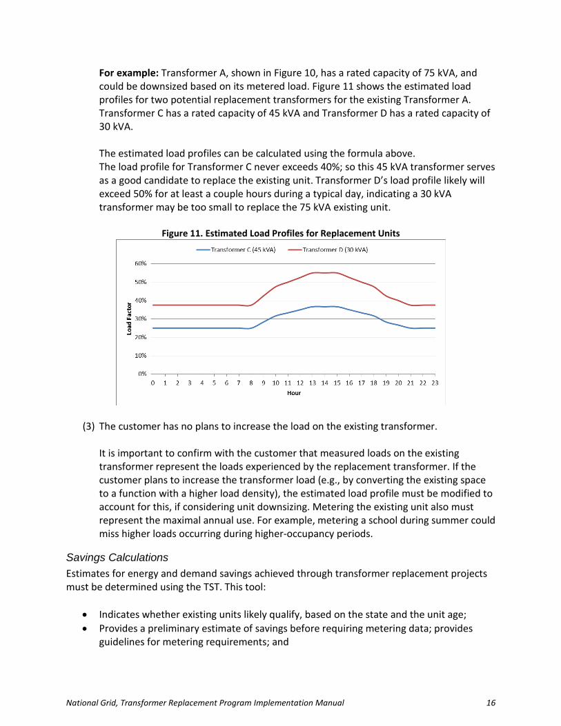
For example: Transformer A, shown in Figure 10, has a rated capacity of 75 kVA, and could be downsized based on its metered load. Figure 11 shows the estimated load profiles for two potential replacement transformers for the existing Transformer A. Transformer C has a rated capacity of 45 kVA and Transformer D has a rated capacity of 30 kVA. The estimated load profiles can be calculated using the formula above. The load profile for Transformer C never exceeds 40%; so this 45 kVA transformer serves as a good candidate to replace the existing unit. Transformer D’s load profile likely will exceed 50% for at least a couple hours during a typical day, indicating a 30 kVA transformer may be too small to replace the 75 kVA existing unit.
Figure 11. Estimated Load Profiles for Replacement Units
(3) The customer has no plans to increase the load on the existing transformer.
It is important to confirm with the customer that measured loads on the existing transformer represent the loads experienced by the replacement transformer. If the customer plans to increase the transformer load (e.g., by converting the existing space to a function with a higher load density), the estimated load profile must be modified to account for this, if considering unit downsizing. Metering the existing unit also must represent the maximal annual use. For example, metering a school during summer could miss higher loads occurring during higher-occupancy periods.
Savings Calculations Estimates for energy and demand savings achieved through transformer replacement projects must be determined using the TST. This tool:
• Indicates whether existing units likely qualify, based on the state and the unit age; • Provides a preliminary estimate of savings before requiring metering data; provides
guidelines for metering requirements; and

National Grid, Transformer Replacement Program Implementation Manual 17
• Calculates energy and demand savings, based on uploaded meter data. See Section 4. for more information about using the tool.
Qualifying Criteria Program contacts should be consulted to determine project eligibility. All projects should receive an incentive preapproval before moving to purchase or installation phases. To qualify for an incentive, a transformer replacement project generally must meet all standard criteria for an custom retrofit project:
• Benefit-Cost Ratio (BCR) ≥ 1 • Customer Simple Payback > 1 and < 15 • Payback with Incentive > 1
BCR ≥ 1 The BCR criterion ensures the project proves cost-effective and the project’s lifetime benefits outweigh project costs. The BCR calculation, performed in the TST, requires the following inputs:
• Annual kWh savings: a value calculated in the tool using the required project inputs. • Peak kW savings: a value calculated in the tool using the required project inputs. • Project lifetime: a value set to 30 for all new transformers. • Material and labor costs for the replacement transformers. These should be the full
costs of the replacement projects, and do not factor in the incentive to reduce the customer’s share of the project costs.
The TST provides many of these inputs, but the project must be screened using the most recent version of the Duel Fuel Custom Screening Tool to calculate the BCR and to indicate whether the project qualifies for an incentive.
Incentive Levels Incentives will be provided to reduce customer costs for qualifying projects. The program manager should be contacted for details regarding project incentives. For the first program year, incentive levels must be determined using the custom screening tool.
National Grid, Transformer Replacement Program Implementation Manual 18
Section 3. Transformer Program Application Process This section describes the process for completing an application for a transformer replacement project.
Application Form
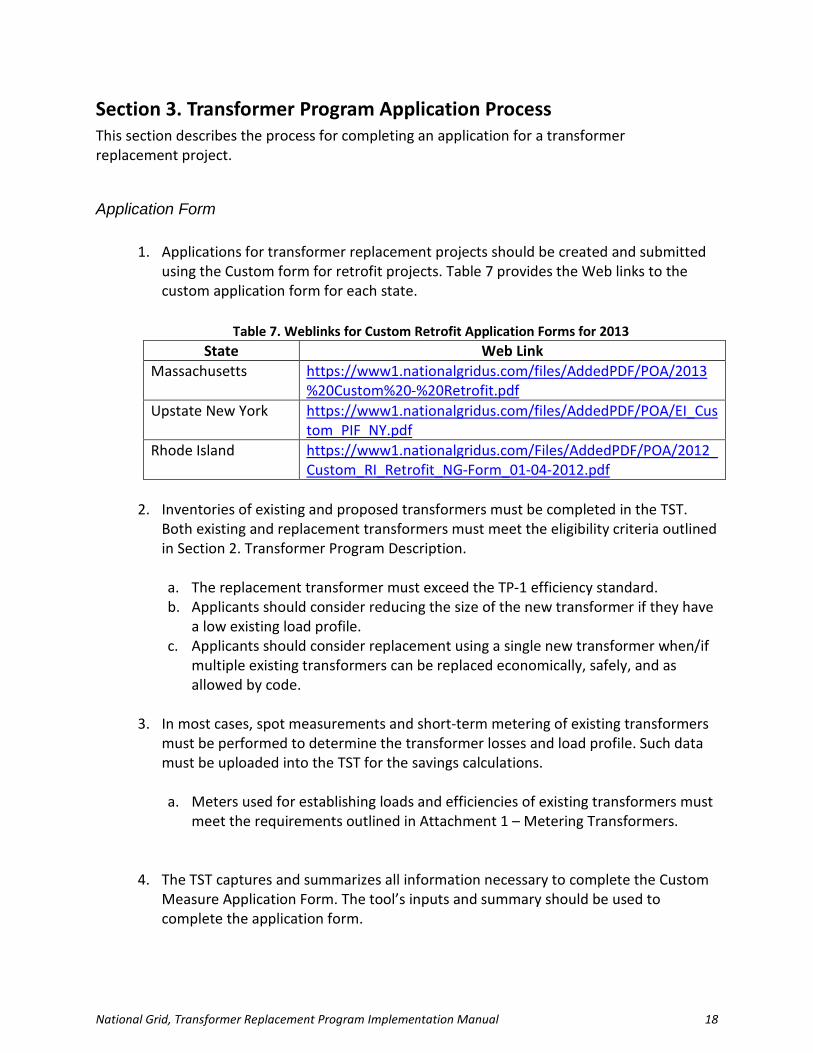
1. Applications for transformer replacement projects should be created and submitted using the Custom form for retrofit projects. Table 7 provides the Web links to the custom application form for each state.
Table 7. Weblinks for Custom Retrofit Application Forms for 2013
State Web Link Massachusetts https://www1.nationalgridus.com/files/AddedPDF/POA/2013
%20Custom%20-%20Retrofit.pdf Upstate New York https://www1.nationalgridus.com/files/AddedPDF/POA/EI_Cus
tom_PIF_NY.pdf Rhode Island https://www1.nationalgridus.com/Files/AddedPDF/POA/2012_
Custom_RI_Retrofit_NG-Form_01-04-2012.pdf
2. Inventories of existing and proposed transformers must be completed in the TST. Both existing and replacement transformers must meet the eligibility criteria outlined in Section 2. Transformer Program Description.
a. The replacement transformer must exceed the TP-1 efficiency standard. b. Applicants should consider reducing the size of the new transformer if they have
a low existing load profile. c. Applicants should consider replacement using a single new transformer when/if
multiple existing transformers can be replaced economically, safely, and as allowed by code.
3. In most cases, spot measurements and short-term metering of existing transformers
must be performed to determine the transformer losses and load profile. Such data must be uploaded into the TST for the savings calculations.
a. Meters used for establishing loads and efficiencies of existing transformers must
meet the requirements outlined in Attachment 1 – Metering Transformers.
4. The TST captures and summarizes all information necessary to complete the Custom
Measure Application Form. The tool’s inputs and summary should be used to complete the application form.

National Grid, Transformer Replacement Program Implementation Manual 19
a. The Energy and Demand Reduction parameters in Table 1 of the Custom form must match the TST.
b. The Cost Estimates in Table 2 of the Custom form must match the values entered into the TST. Documentation for these cost estimates must be provided with the application materials.
c. No non-electric benefits should be claimed for transformer replacement projects. The values in Table 3 of the Custom form should be left blank or set to zero.
d. The TST generates the Minimum Requirements Document (MRD). To complete the MRD for the Custom form, print the MRD page from the TST, and obtain the required signatures.
5. Perform project screening using the Dual Fuel Custom Screening Tool. Savings values
and costs from the TST should be used as inputs in the Custom Screening Tool.
a. Contact the Technical Service Consultant for a copy of the screening tool, or ask them to run the screen, given the savings and costs values on the TST Summary tab.
6. The following documents must be submitted with the project application:
a. A completed TST. b. Excel files with spot-measurement and short-term power meter data. c. Documentation of project costs estimated. d. A completed MRD. e. Results of the Custom Screening Tool.
Post-Installation Inspection Installation of new transformers must comply with all local, state, and federal requirements, and should be performed as outlined in the project MRD. Once installation has been completed, the customer must provide access to National Grid representatives to perform a post-installation verification inspection of the installed equipment. National Grid is not obligated to pay any incentives until it has performed a satisfactory post-installation verification of the installation. If National Grid determines the project has not been installed in accordance with this program manual or with the terms and conditions described on the Custom Project Application Form, National Grid will have the right to require modifications before making any incentive payments. At its discretion, National Grid may withhold payment of incentives until all project documentation has been submitted.

National Grid, Transformer Replacement Program Implementation Manual 20
Post-Installation Evaluation National Grid must evaluate its energy-efficiency programs to determine the percentage of predicted energy savings actually realized, and to utilize those results to make program improvements. Typically, National Grid performs evaluations of such energy-efficiency projects on a subset of projects each year. National Grid reserves the right to perform monitoring and inspection of any transformer projects for a three-year period following installation completion to evaluate the project’s energy and demand impacts. As a condition of receiving an incentive, the customer agrees to provide access and information to National Grid and to cooperate with National Grid and its selected third-party evaluators regarding such activity.

National Grid, Transformer Replacement Program Implementation Manual 21
Section 4. Transformer Savings Tool This section describes the TST and the step-by-step instructions for using the tool to: collect project information; determine metering and replacement transformer specifications; and calculate project savings parameters. The TST can be made available through requests to the Program Manager. The TST should be used for all transformer replacement projects. It collects all project information required for transformer replacement projects, calculates the project energy and peak demand impacts, and provides the summary information required to: complete a project application form; perform the Custom BCR calculation; determine project incentives; and complete the MRD. As project information is updated in the TST, the tool provides: preliminary savings estimates; guidance for the project metering requirements; and recommendations for replacement transformer specifications. Figure 12 shows the process flow for completing the TST.
Figure 12. Process Flow for the TST
[TST] Complete general project information on SUMMARY tab
[TST] Inventory existing
transformers on SCREENING tab
[TST] Review transformer eligibility on
SCREENING tab
[TST] Review preliminary savings
estimates on SCREENING tab
Conduct primary and secondary spot
measurements to assess losses
[TST] Enter spot data on SCREENING tab
and review metering recommendation
Indicate planned metering on
SCREENING tab and conduct power
metering
[TST] Complete METER SUMMARY tab and enter data
on METER DATA tab
[TST] Specify replacement
transformers on SCREENING tab
[TST] Review any warning on
SUMMARY tab
[TST] Review project
SUMMARY and UnitSavings tab.
Metering required
Metering not required
[TST] Input Project Costs on SCREENING tab

National Grid, Transformer Replacement Program Implementation Manual 22
Worksheet Descriptions Table 8 describes each Worksheet in the TST Workbook. The last column notes whether each Worksheet requires user inputs.
Table 8. TST Worksheet Descriptions
Worksheet Description Requires Inputs?
Instructions Provides contact information for questions about the program and the step-by-step instructions outlined below.
No
Definitions Provides detailed descriptions of each of the columns in sheets that require user input.
Yes
MRD Shows the completed MRD when all project inputs are completed. Print this Worksheet to show the MRD.
No
SUMMARY Provides project summary information necessary for the project application form.
Yes
Unit Savings Shows the calculated energy and demand savings for each unit in the project.
No
SCREENING Shows the equipment inventory table, which must be filled out by the user.
Yes
METER SUMMARY
Shows the summary table for meter data collecting. User provides information about metering performed and metering equipment specifications.
Yes
METER DATA Stores the meter data uploaded by the user. The data uploaded on this sheet is used to create the unit load profiles.
Yes
Loadshape_ Existing
Shows the hourly load profiles for the existing units based on meter data. This sheet should be reviewed to check the typical loading levels on each existing transformer. This Worksheet is locked and should not be modified by the user.
No
Loadshape_ Replacement
Shows the hourly load profiles for the replacement units, based on meter data and replacement unit specifications. This sheet should be reviewed to check the expected loading levels on each replacement transformer. This Worksheet is locked and should not be modified by the user.
No
MeteredLosses Shows the average hourly profiles for metered losses when power metering is performed (and data entered into the METER DATA tab) for both primary and secondary power.
No
Savings Hourly savings are calculated in this spreadsheet. The top table shows the expected total project savings, based on all project inputs. This Worksheet is locked and should not be modified by the user.
No
Reference Reference tables store information used throughout the workbook. This Worksheet is hidden and locked and should not be modified by the user.
No

National Grid, Transformer Replacement Program Implementation Manual 23
Required Inputs The TST requires the following project inputs:
• General project information: o Customer information o Technical Assitance (TA) Vendor information
• Existing transformers: o Description of locations and loads o Nameplate data (make, model, size [kVA], age)
• Power metering data (existing transformers): o Spot kW measurements o Short-term metering specification o Transformer kW measurements on primary and or secondary
• Replacement transformer information: o Nameplate data (make, model, size [kVA])
• Project costs: o Material and labor cost
All inputs required to perform calculations in the TST are mandatory for the project application process.
National Grid, Transformer Replacement Program Implementation Manual 24
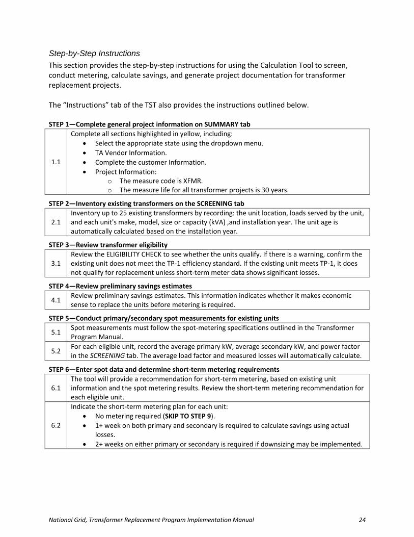
Step-by-Step Instructions This section provides the step-by-step instructions for using the Calculation Tool to screen, conduct metering, calculate savings, and generate project documentation for transformer replacement projects. The “Instructions” tab of the TST also provides the instructions outlined below. STEP 1—Complete general project information on SUMMARY tab
1.1
Complete all sections highlighted in yellow, including: • Select the appropriate state using the dropdown menu. • TA Vendor Information. • Complete the customer Information. • Project Information:
o The measure code is XFMR. o The measure life for all transformer projects is 30 years.
STEP 2—Inventory existing transformers on the SCREENING tab
2.1 Inventory up to 25 existing transformers by recording: the unit location, loads served by the unit, and each unit's make, model, size or capacity (kVA) ,and installation year. The unit age is automatically calculated based on the installation year.
STEP 3—Review transformer eligibility
3.1 Review the ELIGIBILITY CHECK to see whether the units qualify. If there is a warning, confirm the existing unit does not meet the TP-1 efficiency standard. If the existing unit meets TP-1, it does not qualify for replacement unless short-term meter data shows significant losses.
STEP 4—Review preliminary savings estimates
4.1 Review preliminary savings estimates. This information indicates whether it makes economic sense to replace the units before metering is required.
STEP 5—Conduct primary/secondary spot measurements for existing units
5.1 Spot measurements must follow the spot-metering specifications outlined in the Transformer Program Manual.
5.2 For each eligible unit, record the average primary kW, average secondary kW, and power factor in the SCREENING tab. The average load factor and measured losses will automatically calculate.
STEP 6—Enter spot data and determine short-term metering requirements
6.1 The tool will provide a recommendation for short-term metering, based on existing unit information and the spot metering results. Review the short-term metering recommendation for each eligible unit.
6.2
Indicate the short-term metering plan for each unit: • No metering required (SKIP TO STEP 9). • 1+ week on both primary and secondary is required to calculate savings using actual
losses. • 2+ weeks on either primary or secondary is required if downsizing may be implemented.
National Grid, Transformer Replacement Program Implementation Manual 25
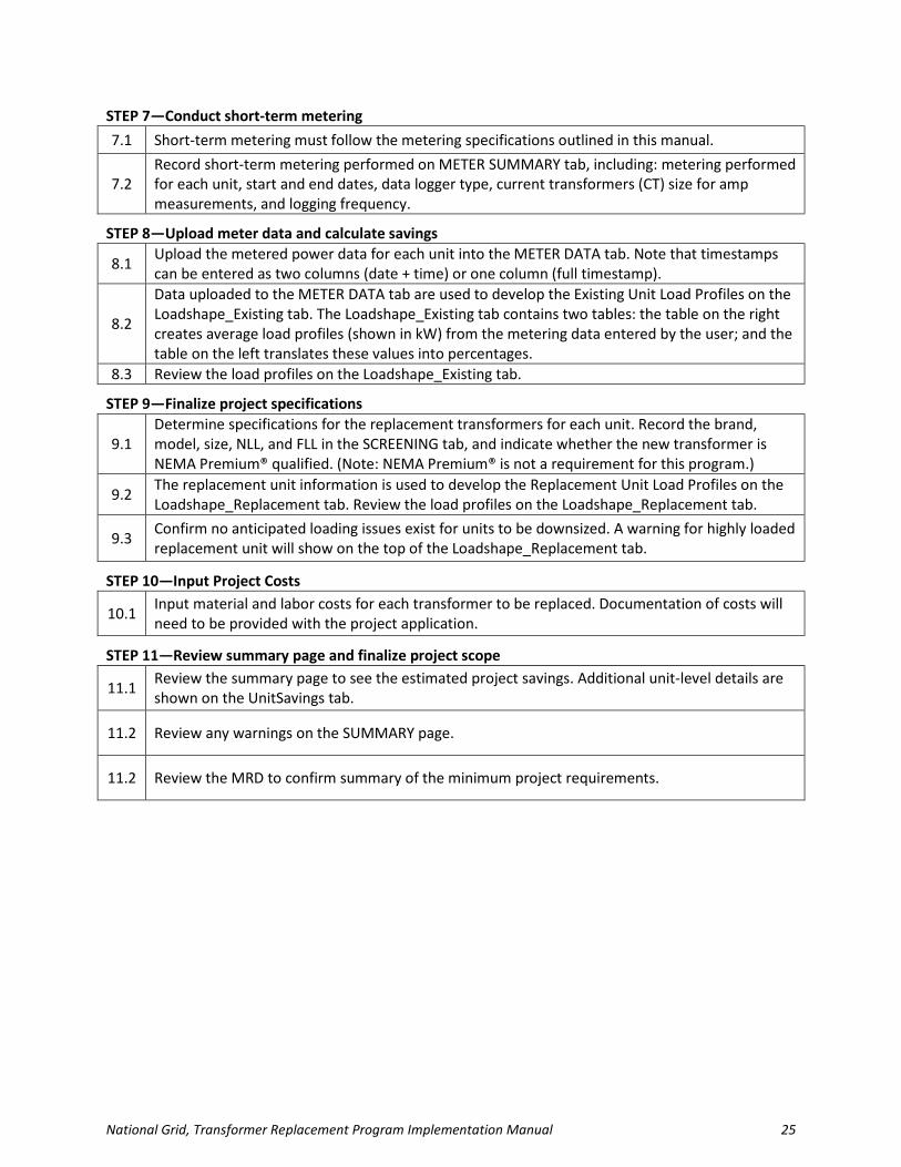
STEP 7—Conduct short-term metering 7.1 Short-term metering must follow the metering specifications outlined in this manual.
7.2 Record short-term metering performed on METER SUMMARY tab, including: metering performed for each unit, start and end dates, data logger type, current transformers (CT) size for amp measurements, and logging frequency.
STEP 8—Upload meter data and calculate savings
8.1 Upload the metered power data for each unit into the METER DATA tab. Note that timestamps can be entered as two columns (date + time) or one column (full timestamp).
8.2
Data uploaded to the METER DATA tab are used to develop the Existing Unit Load Profiles on the Loadshape_Existing tab. The Loadshape_Existing tab contains two tables: the table on the right creates average load profiles (shown in kW) from the metering data entered by the user; and the table on the left translates these values into percentages.
8.3 Review the load profiles on the Loadshape_Existing tab.
STEP 9—Finalize project specifications
9.1 Determine specifications for the replacement transformers for each unit. Record the brand, model, size, NLL, and FLL in the SCREENING tab, and indicate whether the new transformer is NEMA Premium® qualified. (Note: NEMA Premium® is not a requirement for this program.)
9.2 The replacement unit information is used to develop the Replacement Unit Load Profiles on the Loadshape_Replacement tab. Review the load profiles on the Loadshape_Replacement tab.
9.3 Confirm no anticipated loading issues exist for units to be downsized. A warning for highly loaded replacement unit will show on the top of the Loadshape_Replacement tab.
STEP 10—Input Project Costs
10.1 Input material and labor costs for each transformer to be replaced. Documentation of costs will need to be provided with the project application.
STEP 11—Review summary page and finalize project scope
11.1 Review the summary page to see the estimated project savings. Additional unit-level details are shown on the UnitSavings tab.
11.2 Review any warnings on the SUMMARY page.
11.2 Review the MRD to confirm summary of the minimum project requirements.
National Grid, Transformer Replacement Program Implementation Manual 26
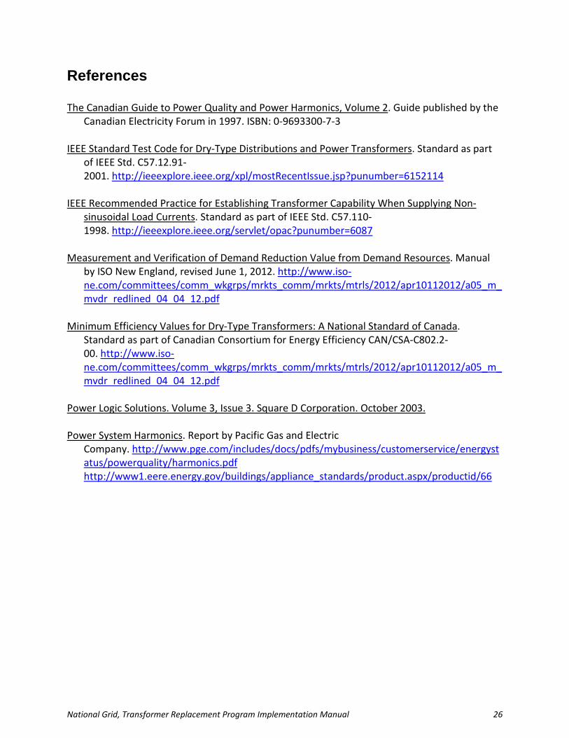
References The Canadian Guide to Power Quality and Power Harmonics, Volume 2. Guide published by the
Canadian Electricity Forum in 1997. ISBN: 0-9693300-7-3 IEEE Standard Test Code for Dry-Type Distributions and Power Transformers. Standard as part
of IEEE Std. C57.12.91-2001. http://ieeexplore.ieee.org/xpl/mostRecentIssue.jsp?punumber=6152114
IEEE Recommended Practice for Establishing Transformer Capability When Supplying Non-
sinusoidal Load Currents. Standard as part of IEEE Std. C57.110-1998. http://ieeexplore.ieee.org/servlet/opac?punumber=6087
Measurement and Verification of Demand Reduction Value from Demand Resources. Manual
by ISO New England, revised June 1, 2012. http://www.iso-ne.com/committees/comm_wkgrps/mrkts_comm/mrkts/mtrls/2012/apr10112012/a05_m_mvdr_redlined_04_04_12.pdf
Minimum Efficiency Values for Dry-Type Transformers: A National Standard of Canada.
Standard as part of Canadian Consortium for Energy Efficiency CAN/CSA-C802.2-00. http://www.iso-ne.com/committees/comm_wkgrps/mrkts_comm/mrkts/mtrls/2012/apr10112012/a05_m_mvdr_redlined_04_04_12.pdf
Power Logic Solutions. Volume 3, Issue 3. Square D Corporation. October 2003. Power System Harmonics. Report by Pacific Gas and Electric
Company. http://www.pge.com/includes/docs/pdfs/mybusiness/customerservice/energystatus/powerquality/harmonics.pdf http://www1.eere.energy.gov/buildings/appliance_standards/product.aspx/productid/66
National Grid, Transformer Replacement Program Implementation Manual 27
Attachment 1—Metering Transformers
Metering Challenges One does not measure the losses of a transformer metered in situ directly, but, rather, one determines losses by subtracting output from input. The percent of losses equal losses divided by the metered input energy. At low loads, losses are the same magnitude of the output power, and small errors in measurement do not appreciably impact the loss calculation. For example, consider a 75 kVA transformer with an output of 6 kW and an input of 5.5 kW. Losses by subtraction would be 500 W, or 8%. As power meters have an accuracy approaching 1%, some uncertainty exists to the loss calculation, but the loss would be known fairly precisely. At a load of 35%, a transformer operates at roughly 98% efficiency, and has losses of about 2%. Assuming power measurements are accurate to 1%, metering errors would be nearly as large as the losses, and the loss calculated by subtraction would be relatively uncertain. Thus, the challenge facing a technician metering the transformer would be to match the equipment to the load, making the measurements as accurate as possible. This could best be done by ensuring: the CTs have been sized to meter the load; and even a spot measurement lasts for 10 minutes to damp out some errors.
Basic Metering Requirements
1. The meter must be rated to give true RMS values of current and voltage. 2. The CTs for the up and downstream metering of the transformer must be sized so loads
fall within the recommended range, typically 5% to 125% of the CT rating. Data outside of these ranges should be discarded.
3. Power must be recorded up and downstream of the transformer, and meters must be launched at the same start time to ensure the two meters collect readings during similar time periods.
4. Power measurements must be averaged through pulse accumulation or by other methods, and averages must be logged at a frequency no less than one logged reading per five minutes.
5. To account for varying schedules and loads, power readings must be logged for at least seven consecutive 24-hour periods for the base condition, and for 14 days for any transformer to be replaced with a smaller size.
6. Power measurements must be converted into watts, and the loss must be calculated by subtracting the transformer output from the transformer input. All zero and negative readings must be discarded.
National Grid, Transformer Replacement Program Implementation Manual 28
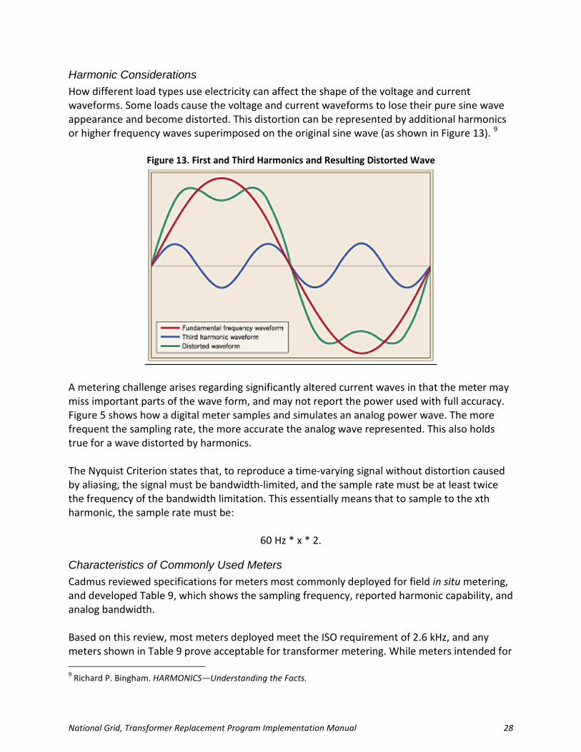
Harmonic Considerations How different load types use electricity can affect the shape of the voltage and current waveforms. Some loads cause the voltage and current waveforms to lose their pure sine wave appearance and become distorted. This distortion can be represented by additional harmonics or higher frequency waves superimposed on the original sine wave (as shown in Figure 13). 9
Figure 13. First and Third Harmonics and Resulting Distorted Wave
A metering challenge arises regarding significantly altered current waves in that the meter may miss important parts of the wave form, and may not report the power used with full accuracy. Figure 5 shows how a digital meter samples and simulates an analog power wave. The more frequent the sampling rate, the more accurate the analog wave represented. This also holds true for a wave distorted by harmonics. The Nyquist Criterion states that, to reproduce a time-varying signal without distortion caused by aliasing, the signal must be bandwidth-limited, and the sample rate must be at least twice the frequency of the bandwidth limitation. This essentially means that to sample to the xth harmonic, the sample rate must be:
60 Hz * x * 2.
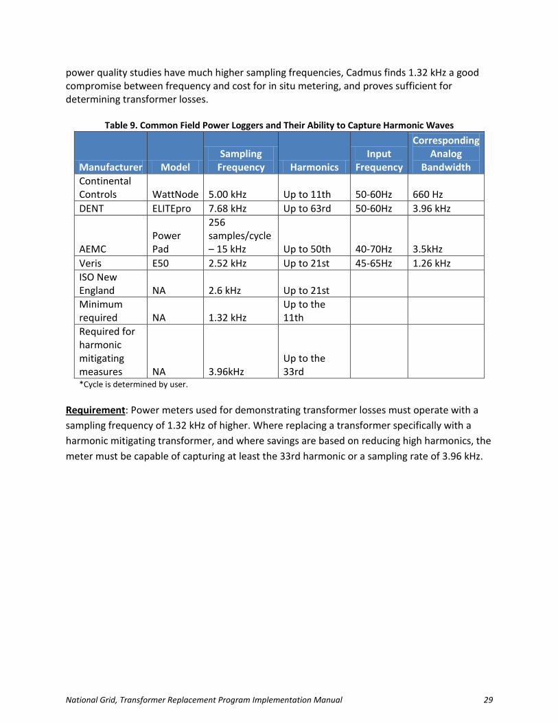
Characteristics of Commonly Used Meters Cadmus reviewed specifications for meters most commonly deployed for field in situ metering, and developed Table 9, which shows the sampling frequency, reported harmonic capability, and analog bandwidth. Based on this review, most meters deployed meet the ISO requirement of 2.6 kHz, and any meters shown in Table 9 prove acceptable for transformer metering. While meters intended for 9 Richard P. Bingham. HARMONICS—Understanding the Facts.
National Grid, Transformer Replacement Program Implementation Manual 29
power quality studies have much higher sampling frequencies, Cadmus finds 1.32 kHz a good compromise between frequency and cost for in situ metering, and proves sufficient for determining transformer losses.
Table 9. Common Field Power Loggers and Their Ability to Capture Harmonic Waves
Manufacturer Model Sampling
Frequency Harmonics Input
Frequency
Corresponding Analog
Bandwidth Continental Controls WattNode 5.00 kHz Up to 11th 50-60Hz 660 Hz DENT ELITEpro 7.68 kHz Up to 63rd 50-60Hz 3.96 kHz
AEMC Power Pad
256 samples/cycle – 15 kHz Up to 50th 40-70Hz 3.5kHz
Veris E50 2.52 kHz Up to 21st 45-65Hz 1.26 kHz ISO New England NA 2.6 kHz Up to 21st Minimum required NA 1.32 kHz
Up to the 11th
Required for harmonic mitigating measures NA 3.96kHz
Up to the 33rd
*Cycle is determined by user. Requirement: Power meters used for demonstrating transformer losses must operate with a sampling frequency of 1.32 kHz of higher. Where replacing a transformer specifically with a harmonic mitigating transformer, and where savings are based on reducing high harmonics, the meter must be capable of capturing at least the 33rd harmonic or a sampling rate of 3.96 kHz.

National Grid, Transformer Replacement Program Implementation Manual 30
Meters and Power Harmonics
CCS WattNode (http://www.ccontrolsys.com/ww/images/3/3e/Data_Sheet_WNB_Pulse.pdf) (http://www.eetasia.com/ARTICLES/2001OCT/2001OCT04_HBM_AN2.PDF?SOURCES=DOWNLOAD)
(http://www.ccontrolsys.com/w/Internal_Computations)
• Sampling Frequency: 5.00 kHz • The WattNode measures harmonic energy, but its solid-state measurement circuitry
cannot make measurements if the noise level is too high. • “Too high” is assumed to be anything above the 11th harmonic.
DENT ELITEpro (http://www.goodmart.com/products/dent-instruments-elitepro-indoor-
recording-poly-phase-power-meter-512kb-line-power-ep-u-h-ps-d-c.htm) (http://www.goodmart.com/pdfs/dent/elitepro.pdf)
• Harmonic Level: to the 63rd harmonic. • Sampling Frequency: 7.68 kHz (128 points per current waveform).
AEMC Power Pad (http://www.aemc.com/products/index.asp) (http://www.instrumart.com/products/34388/aemc-powerpad-model-3945-b-power-
quality-analyzer) (http://www.instrumart.com/assets/AEMC-3945-B-Data-Sheet.pdf)
• Measurement of harmonic angles and rates (referenced to the fundamental or RMS value) for voltage, current, or power, up to 50th harmonic.
• Display of harmonic sequencing and direction, and of calculation of overall harmonics. • Recording, time stamping, and characterization of disturbance (swells, sags and
interruptions; exceedence of power; and harmonic thresholds). • Sampling Frequency: 256 samples/cycle.
Veris E50 (http://www.powermeterstore.com/crm_uploads/veris_e50b1_installation_guide.pdf)
• Sample Rate: 2,520 samples per second. • Type of measurement: True RMS, up to the 21st harmonic @ 60 Hz.