Failure of Circuit Breaker at Ranasan and Transformer at Limdi ...
Upload
michaeljmackCategory
view
138download
3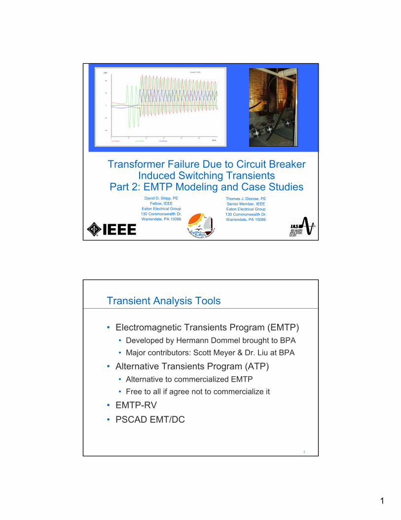
1
Transformer Failure Due to Circuit Breaker Induced Switching Transients
Part 2: EMTP Modeling and Case StudiesDavid D. Shipp, PE
Fellow, IEEEEaton Electrical Group130 Commonwealth Dr.Warrendale, PA 15086
Thomas J. Dionise, PESenior Member, IEEEEaton Electrical Group130 Commonwealth Dr.Warrendale, PA 15086
2 2
Transient Analysis Tools
• Electromagnetic Transients Program (EMTP)• Developed by Hermann Dommel brought to BPA• Major contributors: Scott Meyer & Dr. Liu at BPA
• Alternative Transients Program (ATP)• Alternative to commercialized EMTP• Free to all if agree not to commercialize it
• EMTP-RV• PSCAD EMT/DC

2
3 3
ATP
• ATP Draw interface• 3-phase modeling• Solution method - Trapezoidal integration
• Robust for wide variety of modeling needs
• Extensive library of models• Many options and features
4 4
Source Model
• “3-phase wye cosine”• Resistance in ohms• Inductance in mili-Henries• Source Impedance
• Z1 and X/R• Z0 and X/R
SYSTEM SOURCEAT 13.8 KV
XUTILRUTIL
VUTIL
UN
U UT
3
5 5
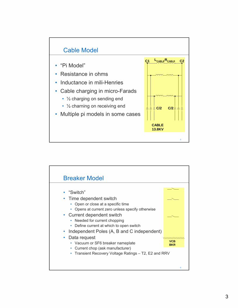
Cable Model
• “Pi Model”• Resistance in ohms• Inductance in mili-Henries• Cable charging in micro-Farads
• ½ charging on sending end• ½ charning on receiving end
• Multiple pi models in some cases
CABLE13.8KV
C1 LCABLERCABLE C2
C/2C/2
6 6
Breaker Model
• “Switch”• Time dependent switch
• Open or close at a specific time• Opens at current zero unless specify otherwise
• Current dependent switch• Needed for current chopping• Define current at which to open switch
• Independent Poles (A, B and C independent)• Data request
• Vacuum or SF6 breaker nameplate• Current chop (ask manufacturer)• Transient Recovery Voltage Ratings – T2, E2 and RRV
VCBBKR

4
7 7
Transformer Model
• “Three Phase Model”• Resistance in ohms• Inductance in mili-Henries• Magnetizing current• Winding capacitance
• CH and CL for dry-types• CHL for oil-filled
• More detailed modeling• Saturation• Hysteresis
• Data Request• %Z and X/R, MVA• BIL TRANSFORMER
RLRG
LTRAN RTRANT1 T2
CH CL
N:1
8 8
Complete System Model
TRANSFORMER
RLRG
LTRAN RTRANT1 T2
CH CL
N:1
CABLE13.8KV
C1 LCABLERCABLE C2
C/2C/2
SYSTEM SOURCEAT 13.8 KV
XUTILRUTIL
VUTIL
UN
U UT
VCBBKR
5
9 9
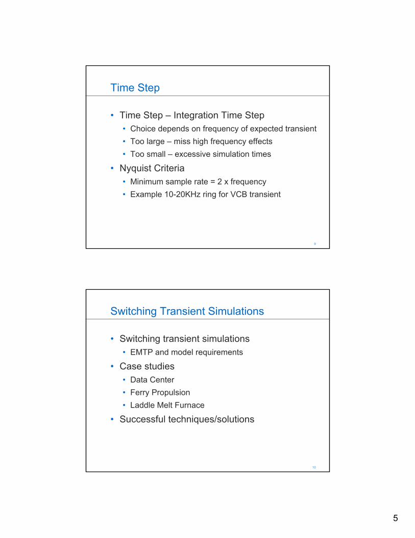
Time Step
• Time Step – Integration Time Step• Choice depends on frequency of expected transient• Too large – miss high frequency effects• Too small – excessive simulation times
• Nyquist Criteria• Minimum sample rate = 2 x frequency• Example 10-20KHz ring for VCB transient
10 10
Switching Transient Simulations
• Switching transient simulations• EMTP and model requirements
• Case studies• Data Center• Ferry Propulsion• Laddle Melt Furnace
• Successful techniques/solutions

6
11 11
Ferry Propulsion
Highlights• 60K passengers per day• 20M passengers per year• 4160V distribution• 3 x 2865kW diesel gens• 2 x 1865KW forward propulsion motors• 2 x 1865KW reverse propulsion
12 12
Problem
• Forward propulsion drives ferry• Upon reaching dock, reverse propulsion stops ferry• July 1, 2009, reverse propulsion was lost entering dock
• lost power and hit a pier at full speed• one serious injury and nine minor injuries• 750 to 800 passengers were aboard • impact did not send any passengers overboard
• 1185KVA rectifier transformer failed on reverse propulsion motor
• Evidence of insulation failure on first few turns of primary winding
• Investigation into source of such failure VCB switching
7
13 13
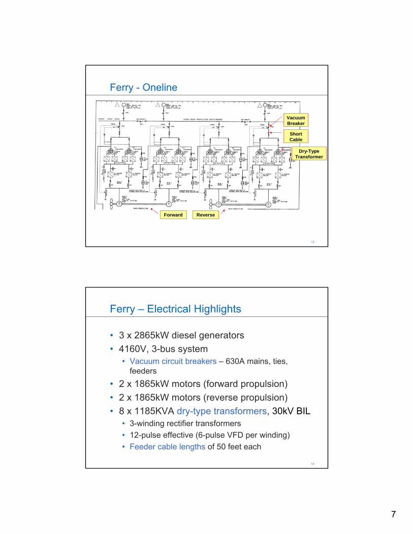
Ferry - Oneline
VacuumBreaker
Short Cable
Dry-Type Transformer
Forward Reverse
14 14
Ferry – Electrical Highlights
• 3 x 2865kW diesel generators• 4160V, 3-bus system
• Vacuum circuit breakers – 630A mains, ties, feeders
• 2 x 1865kW motors (forward propulsion)• 2 x 1865kW motors (reverse propulsion)• 8 x 1185KVA dry-type transformers, 30kV BIL
• 3-winding rectifier transformers• 12-pulse effective (6-pulse VFD per winding)• Feeder cable lengths of 50 feet each
8
15 15
Worst Case Scenarios
• Feeder cable lengths of 50 feet• Each 1185KVA transformer has one 4160V feeder• Need to examine both feeders for each transformer• “Worst Case” Switching Transient Simulations
• Close 4160V VCB to transf. with 50ft. cable (model validation)• Close 4160V VCB to transf. with 50ft. cable (re-ignition)• Open 4160V VCB to transf. with 50ft. cable (current chop)
• Repeat each case with Snubber
16 16
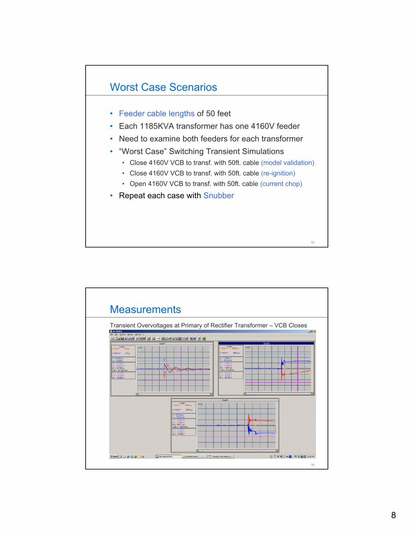
MeasurementsTransient Overvoltages at Primary of Rectifier Transformer – VCB Closes

9
17 17
Study Cases
• Case 1 – Closing the 4.16 kV feeder breaker feeding the three winding rectifier transformer with the distance of 50 feet. Simulated to match the Siemens measurements to ensure that the computer model is accurate. (Model Validation)
• Case 2 – Same as Case 1, except with the RC snubber.• Case 3 - Closing the 4.16 kV feeder breaker feeding the three
winding rectifier transformer, then the 4.16 kV feeder breaker opens during the inrush current. Shows the possibility of the vacuum breaker re-ignition. (Re-ignition)
• Case 4 - Same as Case 3, except with the RC snubber.• Case 5 - Open the 4.16 kV feeder breaker feeding the three
winding rectifier transformer under the light load condition. (Current Chop)
• Case 6 – Same as Case 5, except with the RC snubber.
18 18
Case 1 – Model ValidationTransformer primary voltage
V max of 4.96kV < 30kV BILOscillation of 20,203Hz > 1000Hz
10
19 19
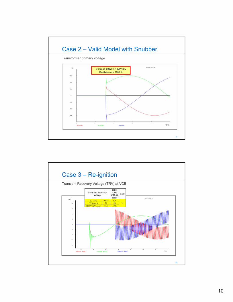
Case 2 – Valid Model with SnubberTransformer primary voltage
V max of 3.982kV < 30kV BILOscillation of < 1000Hz
20 20
Case 3 – Re-ignitionTransient Recovery Voltage (TRV) at VCB

11
21 21
Case 4 – Re-ignition with SnubberTransient Recovery Voltage (TRV) at VCB
22 22
Case 5 – Current ChopTransformer primary voltage
V max of 31.9kV > 30kV BILOscillation of 958Hz ~ 1000Hz
12
23 23
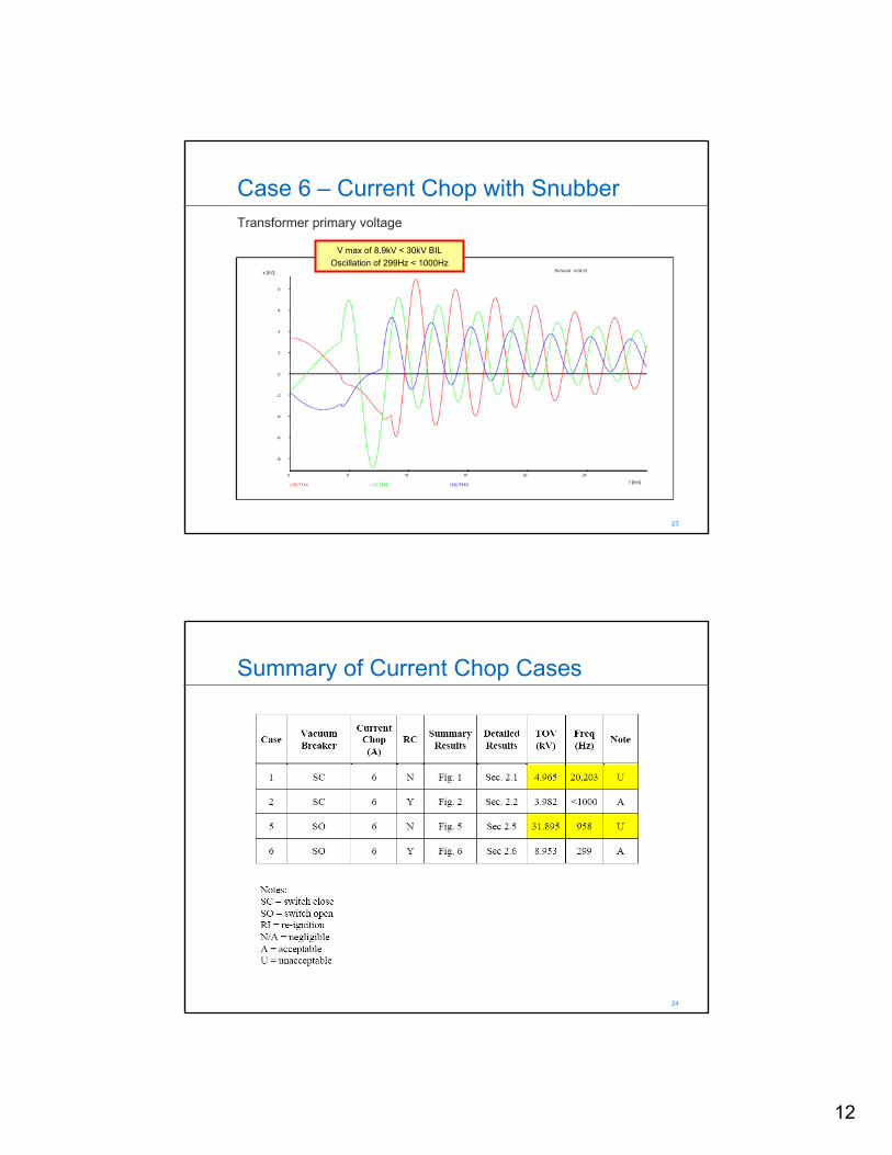
Case 6 – Current Chop with SnubberTransformer primary voltage
V max of 8.9kV < 30kV BILOscillation of 299Hz < 1000Hz
24 24
Summary of Current Chop Cases

13
25 25
Summary of Re-Ignition Cases
26 26
Recommendations
• Install snubber at primary of each 1185KVA rectifier transformer
• 40ohm resistor• Non-inductive• Peak voltage – 6 kVpeak• Peak energy – 2100 Joules• Average power – 190 Watt
• 0.5uF capacitor• Rated voltage - 4.16kV
14
27 27
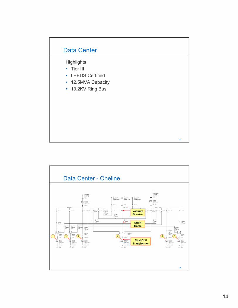
Data Center
Highlights• Tier III• LEEDS Certified• 12.5MVA Capacity• 13.2KV Ring Bus
28 28
Data Center - Oneline
VacuumBreaker
Short Cable
Cast-Coil Transformer

15
29 29
Data Center – Electrical Highlights
• 2 x 24.9 kV lines from Factory Shoals and Buzzard Roast
• 2 x 12.5 MVA transformers • 13.2 kV “ring-bus” configuration
• MSA and MSB and generator bus GPS• Vacuum circuit breakers – 600A mains & ties, 200A feeders
• 3 x 2250 KW generators• 6 x 3750KVA cast coil transformers, 90kV BIL
• 3 x DE Subs CSA, CSB and CSC• 3 x SE Subs MDSA, MDSB and MLB• Feeder cable lengths vary from 109 to 249 Feet
30 30
Worst Case Scenario
• Feeder cable lengths vary from 109 to 249 Feet• Each 3750KVA transformer has two 13.2kV feeders• Need to examine both feeders for each transformer• Shortest of all 13.2kV cable runs to 3750KVA
Transformers• MSB to Transformer CSC – 109 feet• MSA to Transformer CSC – 111 feet
• “Worst Case” Switching Transient Simulation• Open 13.2 kV VCB at MSB to CSC with 109ft. cable• Open 13.2 kV VCB at MSA to CSC with 111ft. cable

16
31 31
Worst Case – Study Case 13
• Study Case 13 - Open the 13.2 kV feeder breaker at Bus MSB feeding the 3,750 kVA dry type transformer CSC with the shorter distance of 109 feet. The result for this case will represent the “worst-case” condition, the other feeder from Bus MSA has a longer feeder distance of 111 feet.
• Study Case 14 – Same as Case 13, except with the application of the 0.25 μF surge capacitor.
• Study Case 15 – Same as Case 13, except with the application of the snubber circuit with 30ohm and 0.25 μF surge capacitor.
32 32
Case 13 – no surge protectionLoad current at 13.2kV VCB
Load current of 10A
Chopped current of 6A
17
33 33
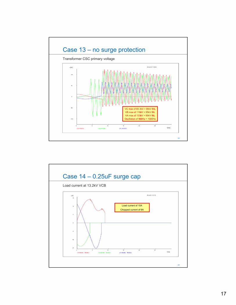
Case 13 – no surge protectionTransformer CSC primary voltage
VC max of 65.3kV > 95kV BILVB max of 116kV > 95kV BILVA max of 123kV > 95kV BILOscillation of 969Hz > 1000Hz
34 34
Case 14 – 0.25uF surge capLoad current at 13.2kV VCB
Load current of 10A
Chopped current of 6A

18
35 35
Case 14 – 0.25uF surge capTransformer CSC primary voltage
VA max of 29.4kV < 95kV BILVB max of 19.1kV < 95kV BIL VC max of 15.7kV < 95kV BIL Oscillation of 215Hz < 1000Hz
36 36
Case 15 – snubber 30ohm and 0.25uFLoad current at 13.2kV VCB
Load current of 10A
Chopped current of 6A
19
37 37
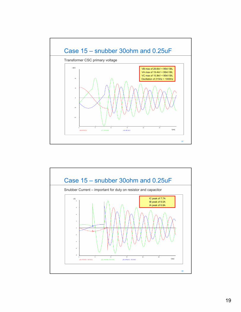
Case 15 – snubber 30ohm and 0.25uFTransformer CSC primary voltage
VB max of 28.6kV < 95kV BILVA max of 19.4kV < 95kV BIL VC max of 15.9kV < 95kV BIL Oscillation of 215Hz < 1000Hz
38 38
Case 15 – snubber 30ohm and 0.25uFSnubber Current – important for duty on resistor and capacitor
IC peak of 7.7AIB peak of 8.0A IA peak of 6.8A
20
39 39
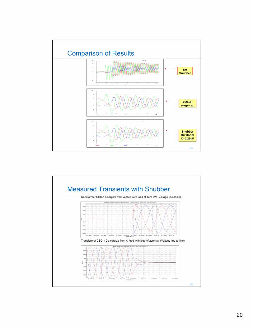
Comparison of Results
No Snubber
0.25uF surge cap
SnubberR=30ohmC=0.25uF
40 40
Measured Transients with Snubber
21
41 41
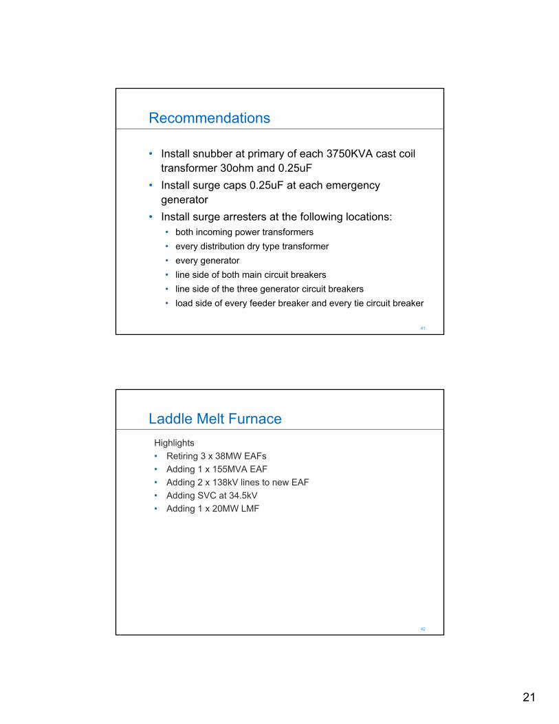
Recommendations
• Install snubber at primary of each 3750KVA cast coil transformer 30ohm and 0.25uF
• Install surge caps 0.25uF at each emergency generator
• Install surge arresters at the following locations:• both incoming power transformers• every distribution dry type transformer• every generator• line side of both main circuit breakers• line side of the three generator circuit breakers• load side of every feeder breaker and every tie circuit breaker
42 42
Laddle Melt FurnaceHighlights• Retiring 3 x 38MW EAFs• Adding 1 x 155MVA EAF• Adding 2 x 138kV lines to new EAF• Adding SVC at 34.5kV• Adding 1 x 20MW LMF

22
43 43
LMF & EAF - Oneline
VacuumBreaker
Short Bus
Oil-Filled Transformer
Existing EAF New
LMF
44 44
138KV
UTILITY4713MVA 3PH SC9.26 X/R
50/66/83MVA135.3/26.4KV
7.5%Z
SF-6 BREAKER2000A
1600A
27KV13OHM
AUTO LTC56MVA
27-10KV3.3%Z
ALUMINUMIPS BUS53FEET
VACUUM BREAKER1200A
LMF XFMR50/56MVA25/.53KV
2.5%Z
HEAVY DUTYCOPPER PIPE
28FEET
LMF20MW
LMF
VacuumBreaker
Short Bus
Oil-Filled Furnace
TransformerNewLMF
SF6Breaker
Short Bus
Oil-Filled Auto-Regulating
Transformer

23
45 45
LMF Circuit – Electrical Highlights
• 50MVA Power Transformer 135/26.4kV• 27kV system
• SF6 circuit breaker – 2000A• Bus length of 53 feet• 56MVA autoregulating transformer, 200kV BIL• Vacuum circuit breaker – 1200A• Bus length of 28 feet• 50MVA oil-filled LMF transformer, 200kV BIL
• 20MW LMF
46 46
Worst Case Scenarios
• Examine switching transients at both transformers• “Worst Case” Switching Transients for Auto-Reg Transf
• Open SF6 breaker to transf. with 53ft. bus (6A current chop)• 3 cycles after energizing Auto-Reg Tran, open SF6 bkr to transf.
with 53ft. bus (re-ignition) highly inductive current
• “Worst Case” Switching Transients for LMF Transf• Open VCB to transf. with 28ft. bus (6A current chop)• 3 cycles after energizing LMF Tran, open VCB to transf. with
28ft. bus (re-ignition) highly inductive current
• Repeat each case with Snubber

24
47 47
Case 1 – Open VCBLMF Transformer primary voltage
V max of 386kV > 200kV BILOscillation of 1217Hz > 1000Hz
48 48
Case 2 – Open VCB with SnubberLMF Transformer primary voltage
V max of 56.4kV < 200kV BILOscillation of 200Hz < 1000Hz

25
49 49
Case 3 – Open SF6 BreakerAuto-regulating Transformer primary voltage
V max of 23kV < 200kV BILNo oscillating frequency
50 50
Case 4 – Open SF6 Breaker with SnubberAuto-regulating Transformer primary voltage
VB max of 54.7kV < 200kV BILOscillation of 197Hz < 1000Hz
26
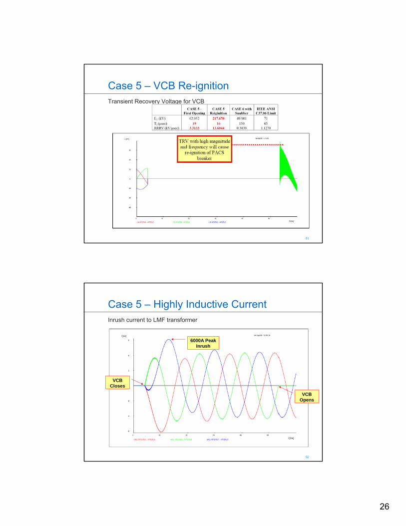
51 51
Case 5 – VCB Re-ignitionTransient Recovery Voltage for VCB
52 52
Case 5 – Highly Inductive CurrentInrush current to LMF transformer
6000A Peak Inrush
VCB Opens
VCB Closes

27
53 53
Case 6 – VCB Re-ignition & SnubberTransient Recovery Voltage for VCB
54 54
Case 7 – SF6 Breaker Re-ignitionTransient Recovery Voltage for Siemens SF6

28
55 55
Case 7 – Highly Inductive CurrentInrush current to Auto-Regulating transformer
14000A Peak Inrush
SF6 CB Opens
SF6 CB Closes
56 56
Case 8 – SF6 Breaker Re-ignition & SnubberTransient Recovery Voltage for SF6 Breaker

29
57 57
Summary of Current Chop Cases
58 58
Summary of Re-Ignition Cases
30
59 59
Recommendations
• Install snubber (100ohm and 0.15uF) at primary of each transformer
• 100ohm resistor• Non-inductive• Peak voltage – 38 kVpeak• Peak energy – 17,500 Joules• Average power – 1000 Watt
• 0.15uF, 34.5kV surge capacitor (not available)• 1-pole, 24kV, 0.13uF• 2-pole, 14.4kV, 0.5uF• Series combination gives 0.103uF