Transform Instructions - 34106947 - The Home Depot · Pre-drill using a ¼" drill bit through ......
16
INSTALLATION INSTRUCTIONS • Level Rail ......................................... 2 • Level Angle ....................................... 8 • Stair Rail .......................................... 9 • Care & Maintenance, Finishing ...... 15 TRANSFORM TM
Transcript of Transform Instructions - 34106947 - The Home Depot · Pre-drill using a ¼" drill bit through ......

INSTALLATION INSTRUCTIONS
• Level Rail ......................................... 2• Level Angle ....................................... 8• Stair Rail .......................................... 9• Care & Maintenance, Finishing ...... 15
TRANSFORM
TM
2
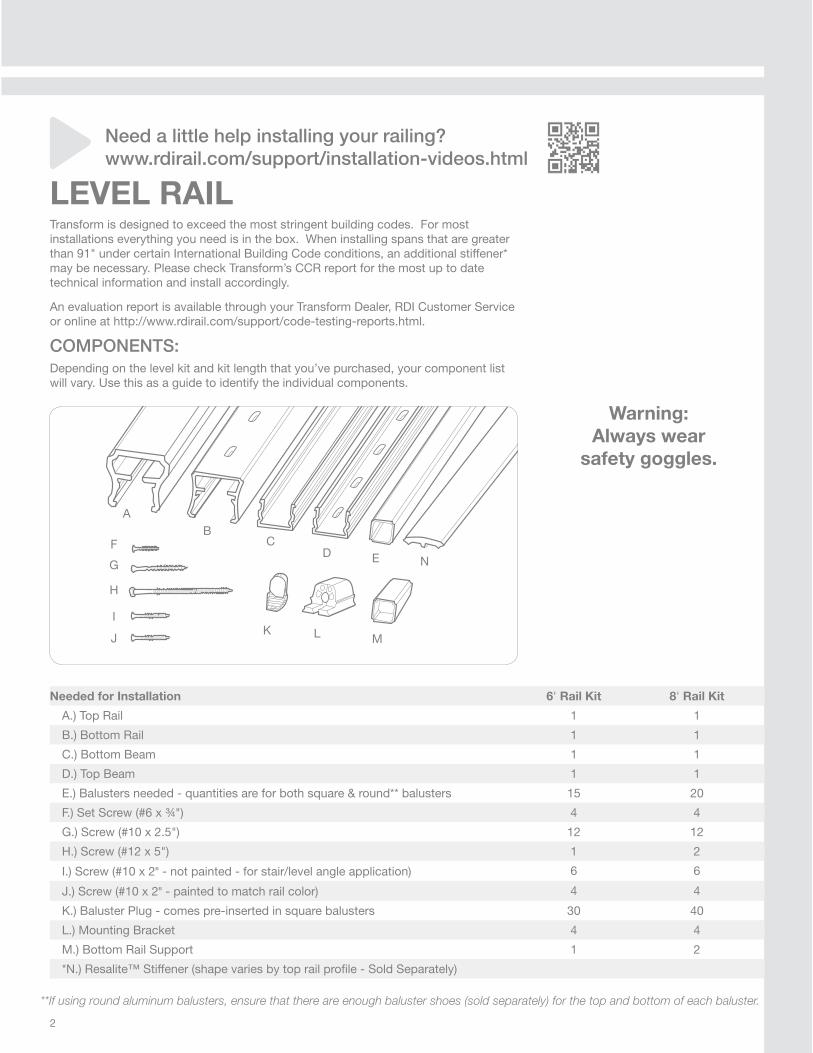
LEVEL RAILTransform is designed to exceed the most stringent building codes. For most installations everything you need is in the box. When installing spans that are greater than 91" under certain International Building Code conditions, an additional stiffener* may be necessary. Please check Transform’s CCR report for the most up to date technical information and install accordingly.
An evaluation report is available through your Transform Dealer, RDI Customer Service or online at http://www.rdirail.com/support/code-testing-reports.html.
COMPONENTS:Depending on the level kit and kit length that you’ve purchased, your component list will vary. Use this as a guide to identify the individual components.
Warning:
Always wear
safety goggles.
Needed for Installation 6' Rail Kit 8' Rail Kit
A.) Top Rail 1 1
B.) Bottom Rail 1 1
C.) Bottom Beam 1 1
D.) Top Beam 1 1
E.) Balusters needed - quantities are for both square & round** balusters 15 20
F.) Set Screw (#6 x ¾") 4 4
G.) Screw (#10 x 2.5") 12 12
H.) Screw (#12 x 5") 1 2
I.) Screw (#10 x 2" - not painted - for stair/level angle application) 6 6
J.) Screw (#10 x 2" - painted to match rail color) 4 4
K.) Baluster Plug - comes pre-inserted in square balusters 30 40
L.) Mounting Bracket 4 4
M.) Bottom Rail Support 1 2
*N.) Resalite™ Stiffener (shape varies by top rail profi le - Sold Separately)
Need a little help installing your railing?
www.rdirail.com/support/installation-videos.html
**If using round aluminum balusters, ensure that there are enough baluster shoes (sold separately) for the top and bottom of each baluster.
AB
CD
F
H
G
I
E
JK L M
N
3
(Fig. 1)
(Fig. 2)
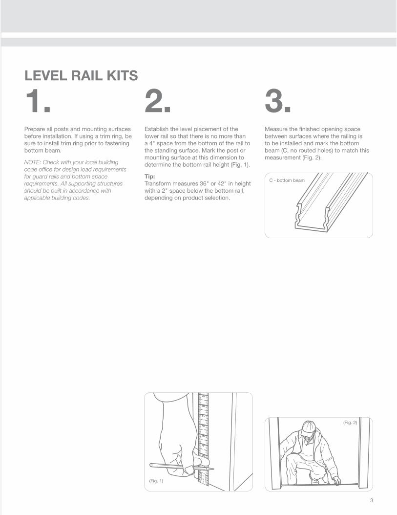
C - bottom beam
1.Prepare all posts and mounting surfaces before installation. If using a trim ring, be sure to install trim ring prior to fastening bottom beam.
NOTE: Check with your local building
code offi ce for design load requirements
for guard rails and bottom space
requirements. All supporting structures
should be built in accordance with
applicable building codes.
2.Establish the level placement of the lower rail so that there is no more than a 4" space from the bottom of the rail to the standing surface. Mark the post or mounting surface at this dimension to determine the bottom rail height (Fig. 1).
Tip:
Transform measures 36" or 42" in height with a 2" space below the bottom rail, depending on product selection.
3.Measure the fi nished opening space between surfaces where the railing is to be installed and mark the bottom beam (C, no routed holes) to match this measurement (Fig. 2).
LEVEL RAIL KITS
4
(Fig. 3)
(Fig. 5)
(Fig. 6)(Fig. 4)
(Fig. 8)
(Fig. 7)
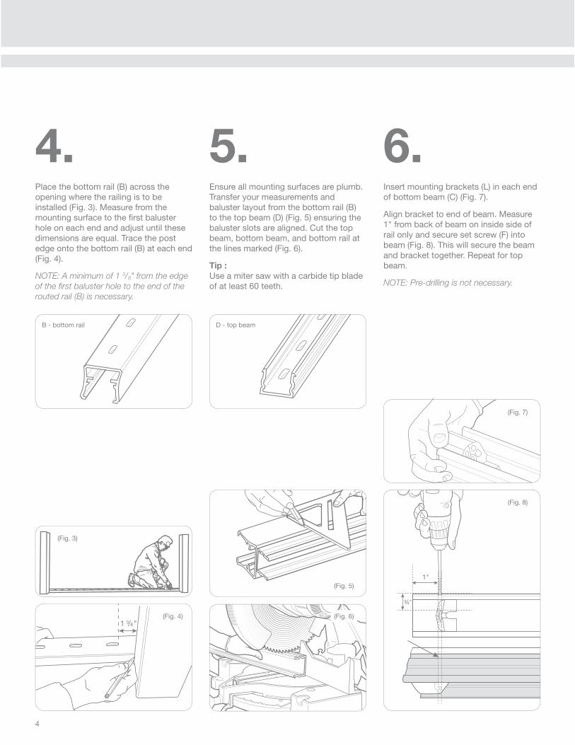
5.Ensure all mounting surfaces are plumb. Transfer your measurements and baluster layout from the bottom rail (B) to the top beam (D) (Fig. 5) ensuring the baluster slots are aligned. Cut the top beam, bottom beam, and bottom rail at the lines marked (Fig. 6).
Tip :
Use a miter saw with a carbide tip blade of at least 60 teeth.
4.Place the bottom rail (B) across the opening where the railing is to be installed (Fig. 3). Measure from the mounting surface to the fi rst baluster hole on each end and adjust until these dimensions are equal. Trace the post edge onto the bottom rail (B) at each end (Fig. 4).
NOTE: A minimum of 1 3/8" from the edge
of the fi rst baluster hole to the end of the
routed rail (B) is necessary.
6.Insert mounting brackets (L) in each end of bottom beam (C) (Fig. 7).
Align bracket to end of beam. Measure 1" from back of beam on inside side of rail only and secure set screw (F) into beam (Fig. 8). This will secure the beam and bracket together. Repeat for top beam.
NOTE: Pre-drilling is not necessary.
B - bottom rail D - top beam

5
(Fig. 9)
(Fig. 10)
(Fig. 11)
(Fig. 12)
(Fig. 13)
7.Align the bottom beam with the marks determined in Step 2.
Secure the lower bracket & beam to the post using 6 mounting screws (G), 3 per bracket (Fig. 9). Begin with the bottom center screw as shown to avoid misalignment.
Tip:
Cut wood blocks to support the bottom beam at the proper height during installation (Fig. 10). Place the blocks under the ends of the rail against the posts
8.Cut the bottom rail support (K) to the bottom space determined in Step 2 and place it under the bottom beam at the center point (Fig. 11 and 12).
If installing a section longer than 6', evenly space the two rail supports along the span of the bottom rail.
Pre-drill using a ¼" drill bit through the beam (Fig. 13). Screw through the bottom beam (C) and bottom rail support (M) into the standing surface with the screws provided (H). Do not over-tighten.
(Fig. 15)
(Fig. 14)
9.Snap the bottom rail (B) over the bottom beam (D) (Fig. 14, 15).
Insert a baluster (E) into each slot of the bottom rail (B) (Fig. 16). Baluster plugs are pre-installed in the baluster for easy assembly. Align the bottom baluster plugs in the same direction when installing into the bottom rail. This will allow the balusters to lean in the same direction and help during installation of the top beam. Lean balusters in the direction of the round edge of the baluster plug as shown in fi gure 17.
(Fig. 17)
(Fig. 16)
6
(Fig. 18) (Fig. 19) (Fig. 21)
(Fig. 20)
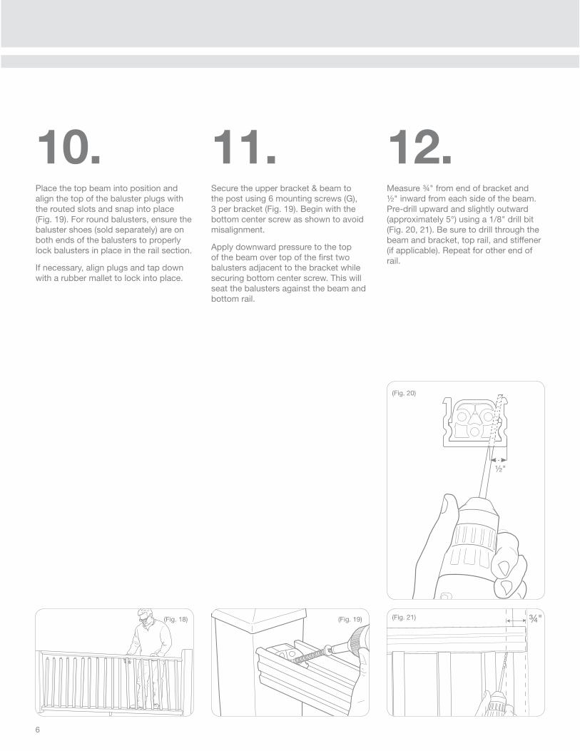
10.Place the top beam into position and align the top of the baluster plugs with the routed slots and snap into place (Fig. 19). For round balusters, ensure the baluster shoes (sold separately) are on both ends of the balusters to properly lock balusters in place in the rail section.
If necessary, align plugs and tap down with a rubber mallet to lock into place.
11.Secure the upper bracket & beam to the post using 6 mounting screws (G), 3 per bracket (Fig. 19). Begin with the bottom center screw as shown to avoid misalignment.
Apply downward pressure to the top of the beam over top of the fi rst two balusters adjacent to the bracket while securing bottom center screw. This will seat the balusters against the beam and bottom rail.
12.Measure ¾" from end of bracket and ½" inward from each side of the beam. Pre-drill upward and slightly outward (approximately 5°) using a 1/8" drill bit (Fig. 20, 21). Be sure to drill through the beam and bracket, top rail, and stiffener (if applicable). Repeat for other end of rail.
½"
7
(Fig. 23)
(Fig. 22)
(Fig. 24) (Fig. 25)
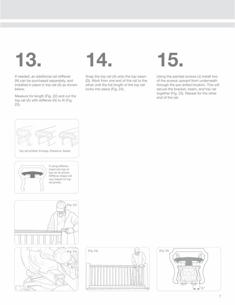
13.If needed, an additional rail stiffener (N) can be purchased separately, and installed in place in top rail (A) as shown below.
Measure for length (Fig. 22) and cut the top rail (A) with stiffener (N) to fi t (Fig. 23).
14.Snap the top rail (A) onto the top beam (D). Work from one end of the rail to the other until the full length of the top rail locks into place (Fig. 24).
15.Using the painted screws (J) install two of the screws upward from underneath through the pre-drilled location. This will secure the bracket, beam, and top rail together (Fig. 25). Repeat for the other end of the rail.
Top rail profi les: Emerge, Presence, Aspire
If using stiffener, insert into top of top rail as shown. Stiffener shape will vary based on top rail profi le.
½"

8
LEVEL ANGLE INSTALLATIONBrackets are designed for use in level angle applications up to 45°. Note that the Presence and Aspire top rails will not fi t on a 5" x 5" post if cut at 45°. Emerge top rail can be cut to 45° and mounted on a 5" x 5" post.
1.Secure brackets into beam using masking tape wrapped around bracket. Mark beam and bracket at desired level angle and cut.
2.Install set screws to wider side of bracket only, as shown in Figure 3, to secure bracket to beam.
3.Secure bracket to post, beginning with the center screw. If using an RDI structural post, you may have to use the shorter 2" unpainted screws (I) provided.
Pre-drill down through top of bracket and top beam in location shown (Fig. 4).
Snap the top rail (A) onto the top beam (D). Work from one end of the rail to the other until the full length of the top rail locks into place. Using the painted screws (J) install two of the screws upward from underneath through the pre-drilled location. This will secure the bracket, beam, and top rail together. Repeat for the other end of the rail.
(Fig. 2)
(Fig. 1) (Fig. 3) (Fig. 4)
9
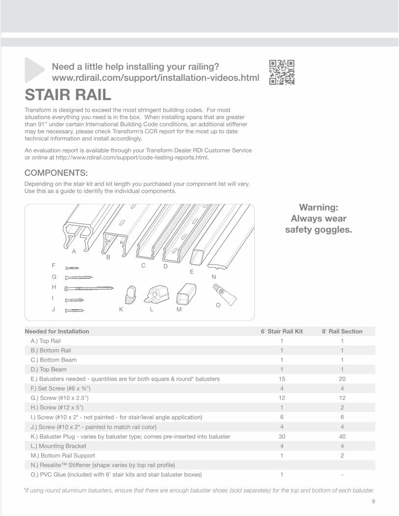
COMPONENTS:Depending on the stair kit and kit length you purchased your component list will vary. Use this as a guide to identify the individual components.
Warning:
Always wear
safety goggles.
Needed for Installation 6' Stair Rail Kit 8' Rail Section
A.) Top Rail 1 1
B.) Bottom Rail 1 1
C.) Bottom Beam 1 1
D.) Top Beam 1 1
E.) Balusters needed - quantities are for both square & round* balusters 15 20
F.) Set Screw (#6 x ¾") 4 4
G.) Screw (#10 x 2.5") 12 12
H.) Screw (#12 x 5") 1 2
I.) Screw (#10 x 2" - not painted - for stair/level angle application) 6 6
J.) Screw (#10 x 2" - painted to match rail color) 4 4
K.) Baluster Plug - varies by baluster type; comes pre-inserted into baluster 30 40
L.) Mounting Bracket 4 4
M.) Bottom Rail Support 1 2
N.) Resalite™ Stiffener (shape varies by top rail profi le)
O.) PVC Glue (included with 6' stair kits and stair baluster boxes) 1 -
*If using round aluminum balusters, ensure that there are enough baluster shoes (sold separately) for the top and bottom of each baluster.
STAIR RAILTransform is designed to exceed the most stringent building codes. For most situations everything you need is in the box. When installing spans that are greater than 91" under certain International Building Code conditions, an additional stiffener may be necessary, please check Transform’s CCR report for the most up to date technical information and install accordingly.
An evaluation report is available through your Transform Dealer RDI Customer Service or online at http://www.rdirail.com/support/code-testing-reports.html.
Need a little help installing your railing?
www.rdirail.com/support/installation-videos.html
AB
C DF
H
J K L M
N
O
GE
I
10
(Fig. 2) (Fig. 3)
(Fig. 1)
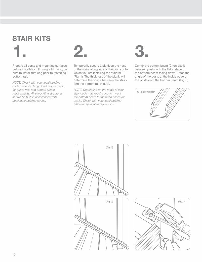
1.Prepare all posts and mounting surfaces before installation. If using a trim ring, be sure to install trim ring prior to fastening bottom rail.
NOTE: Check with your local building
code offi ce for design load requirements
for guard rails and bottom space
requirements. All supporting structures
should be built in accordance with
applicable building codes.
2.Temporarily secure a plank on the nose of the stairs along side of the posts onto which you are installing the stair rail (Fig. 1). The thickness of the plank will determine the space between the stairs and the bottom rail (Fig. 2).
NOTE: Depending on the angle of your
stair, code may require you to mount
the bottom beam to the tread noses (no
plank). Check with your local building
offi ce for applicable regulations.
3.Center the bottom beam (C) on plank between posts with the fl at surface of the bottom beam facing down. Trace the angle of the posts at the inside edge of the posts onto the bottom beam (Fig. 3).
STAIR KITS
C - bottom beam
11
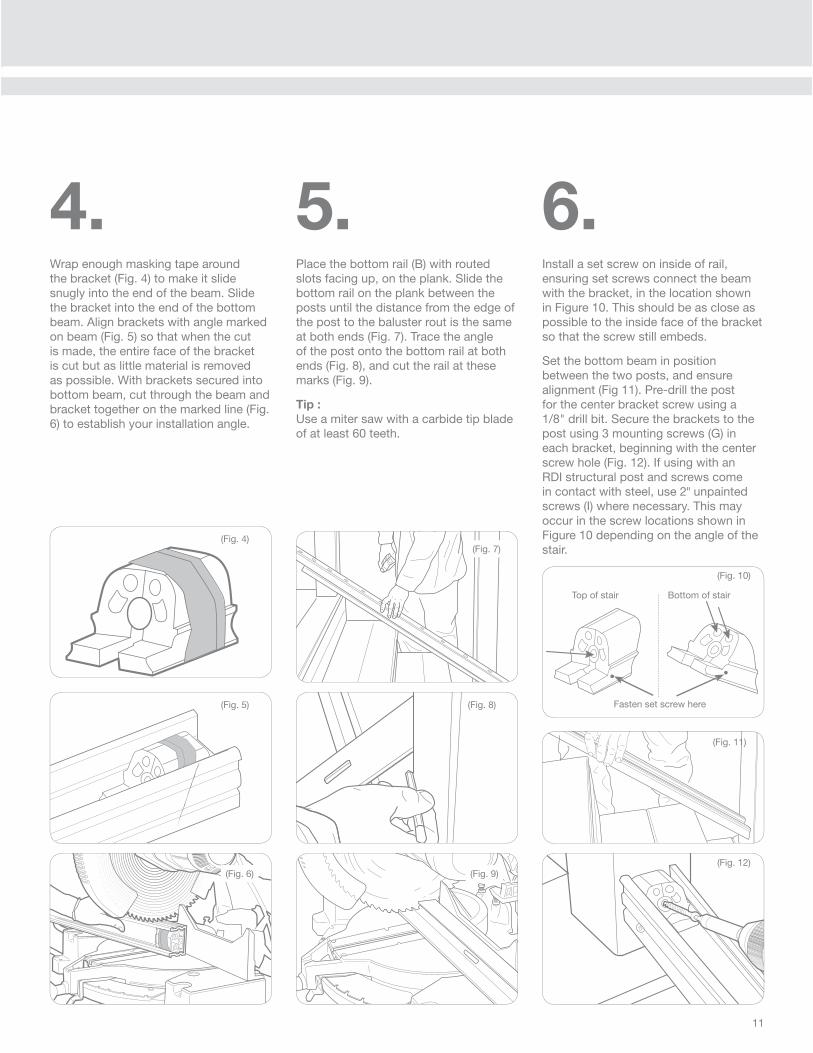
6.Install a set screw on inside of rail, ensuring set screws connect the beam with the bracket, in the location shown in Figure 10. This should be as close as possible to the inside face of the bracket so that the screw still embeds.
Set the bottom beam in position between the two posts, and ensure alignment (Fig 11). Pre-drill the post for the center bracket screw using a 1/8" drill bit. Secure the brackets to the post using 3 mounting screws (G) in each bracket, beginning with the center screw hole (Fig. 12). If using with an RDI structural post and screws come in contact with steel, use 2" unpainted screws (I) where necessary. This may occur in the screw locations shown in Figure 10 depending on the angle of the stair.
5.Place the bottom rail (B) with routed slots facing up, on the plank. Slide the bottom rail on the plank between the posts until the distance from the edge of the post to the baluster rout is the same at both ends (Fig. 7). Trace the angle of the post onto the bottom rail at both ends (Fig. 8), and cut the rail at these marks (Fig. 9).
Tip :
Use a miter saw with a carbide tip blade of at least 60 teeth.
(Fig. 8)
(Fig. 9)(Fig. 12)
(Fig. 11)
4.Wrap enough masking tape around the bracket (Fig. 4) to make it slide snugly into the end of the beam. Slide the bracket into the end of the bottom beam. Align brackets with angle marked on beam (Fig. 5) so that when the cut is made, the entire face of the bracket is cut but as little material is removed as possible. With brackets secured into bottom beam, cut through the beam and bracket together on the marked line (Fig. 6) to establish your installation angle.
(Fig. 5)
(Fig. 7)(Fig. 4)
(Fig. 6)
(Fig. 10)
Fasten set screw here
Top of stair Bottom of stair
12
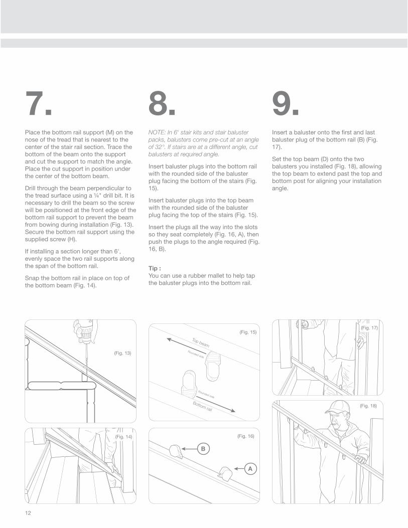
7.Place the bottom rail support (M) on the nose of the tread that is nearest to the center of the stair rail section. Trace the bottom of the beam onto the support and cut the support to match the angle. Place the cut support in position under the center of the bottom beam.
Drill through the beam perpendicular to the tread surface using a ¼" drill bit. It is necessary to drill the beam so the screw will be positioned at the front edge of the bottom rail support to prevent the beam from bowing during installation (Fig. 13). Secure the bottom rail support using the supplied screw (H).
If installing a section longer than 6', evenly space the two rail supports along the span of the bottom rail.
Snap the bottom rail in place on top of the bottom beam (Fig. 14).
(Fig. 14)
(Fig. 18)
(Fig. 17)
(Fig. 16)
(Fig. 13)
8.NOTE: In 6' stair kits and stair baluster
packs, balusters come pre-cut at an angle
of 32°. If stairs are at a different angle, cut
balusters at required angle.
Insert baluster plugs into the bottom rail with the rounded side of the baluster plug facing the bottom of the stairs (Fig. 15).
Insert baluster plugs into the top beam with the rounded side of the baluster plug facing the top of the stairs (Fig. 15).
Insert the plugs all the way into the slots so they seat completely (Fig. 16, A), then push the plugs to the angle required (Fig. 16, B).
Tip :
You can use a rubber mallet to help tap the baluster plugs into the bottom rail.
9.Insert a baluster onto the fi rst and last baluster plug of the bottom rail (B) (Fig. 17).
Set the top beam (D) onto the two balusters you installed (Fig. 18), allowing the top beam to extend past the top and bottom post for aligning your installation angle.
Bottom rail
Top beamRounded side
Rounded side
(Fig. 15)
B
A
13
(Fig. 22)
(Fig. 24)
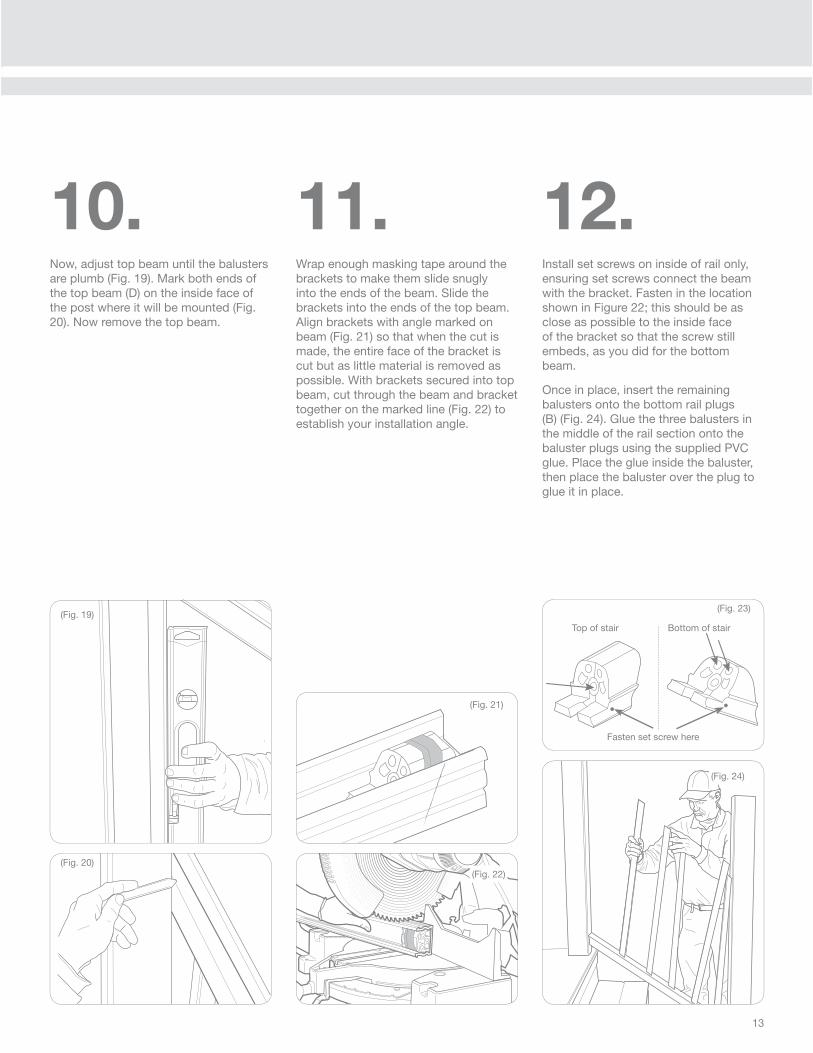
11.Wrap enough masking tape around the brackets to make them slide snugly into the ends of the beam. Slide the brackets into the ends of the top beam. Align brackets with angle marked on beam (Fig. 21) so that when the cut is made, the entire face of the bracket is cut but as little material is removed as possible. With brackets secured into top beam, cut through the beam and bracket together on the marked line (Fig. 22) to establish your installation angle.
12.Install set screws on inside of rail only, ensuring set screws connect the beam with the bracket. Fasten in the location shown in Figure 22; this should be as close as possible to the inside face of the bracket so that the screw still embeds, as you did for the bottom beam.
Once in place, insert the remaining balusters onto the bottom rail plugs (B) (Fig. 24). Glue the three balusters in the middle of the rail section onto the baluster plugs using the supplied PVC glue. Place the glue inside the baluster, then place the baluster over the plug to glue it in place.
(Fig. 21)
(Fig. 23)
Fasten set screw here
Top of stair Bottom of stair(Fig. 19)
(Fig. 20)
10.Now, adjust top beam until the balusters are plumb (Fig. 19). Mark both ends of the top beam (D) on the inside face of the post where it will be mounted (Fig. 20). Now remove the top beam.
14
(Fig. 28)
(Fig. 30)
(Fig. 29)
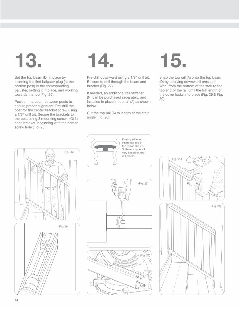
14.Pre-drill downward using a 1/8" drill bit. Be sure to drill through the beam and bracket (Fig. 27).
If needed, an additional rail stiffener (N) can be purchased separately, and installed in place in top rail (A) as shown below.
Cut the top rail (A) to length at the stair angle (Fig. 28).
15.Snap the top rail (A) onto the top beam (D) by applying downward pressure. Work from the bottom of the stair to the top end of the rail until the full length of the cover locks into place (Fig. 29 & Fig. 30).
If using stiffener, insert into top of top rail as shown. Stiffener shape will vary based on top rail profi le.
(Fig. 25)
(Fig. 26)
13.Set the top beam (D) in place by inserting the fi rst baluster plug (at the bottom post) in the corresponding baluster, setting it in place, and working towards the top (Fig. 25).
Position the beam between posts to ensure proper alignment. Pre-drill the post for the center bracket screw using a 1/8" drill bit. Secure the brackets to the post using 3 mounting screws (G) in each bracket, beginning with the center screw hole (Fig. 26).
(Fig. 27)

15
Formula 409® is a registered trademark of The Clorox Company
Glass Plus® is a registered trademark used under authority of Reckitt Benckiser, Llc.
Comet®, Mr. Clean®, and Spic and Span® are registered trademarks of the Procter and
Gamble Company
Soft Scrub® is a registered trademark of Henkel Consumer Goods, Inc.
In general, the following chemicals may be safely used with Transform acrylic capped railing system at ambient temperature conditions:
• Formula 409® Cleaner
• Glass Plus® Cleaner
• Liquid Comet® Cleaner
• Mineral Oil
• Mr. Clean® Cleaner
• Soap and water
• Soft Scrub® Cleaner
• Spic and Span® Cleaner
16.Using the painted screws (J) install two of the screws upward from underneath each end through the pre-drilled location. This will secure the bracket, beam, and top rail together (Fig. 31).
(Fig. 31)
Care & Maintenance:Acrylic capstock resins have good resistance to a variety of common cleaners and application environments. It is recommended that you test any cleaner in an inconspicuous area prior to cleaning Transform railing systems. Use proper safety precautions & follow the manufacturers instructions when working with any chemical agents. Properly dispose of chemicals according to your local municipality’s regulations for chemical disposal.
Mr. Clean® Magic Erasers® (original style) are the recommended method of cleaning all colors of Transform railing products.

RAILING DYNAMICS, INC.
FOR HOME, FOR LIFE®
135 STEELMANVILLE ROAD
EGG HARBOR TOWNSHIP, NJ 08234
TEL: (877) 420-7245
FAX: (866) 277-5160
E-MAIL: [email protected]
URL: WWW.RDIRAIL.COM
34106947 / 12.13
Need a little help installing your railing?
www.rdirail.com/support/installation-videos.html
TM