Transfer Gear Pumps KF3/100KF6/730 · Mounting flange- and angle foot type flanged pipe...
28
Transfer Gear Pumps KF 3/100...KF 6/730
Transcript of Transfer Gear Pumps KF3/100KF6/730 · Mounting flange- and angle foot type flanged pipe...
Transfer Gear Pumps
KF 3/100...KF 6/730
Transfer Gear Pumps KF 3/100...KF 6/730
2
Technical Data
Page
Applications / Suitable fluids . . . . . . . . . . . . . . . . . . . . . . . . . . . . . . . . . . . . . . . . . . . 3
Construction . . . . . . . . . . . . . . . . . . . . . . . . . . . . . . . . . . . . . . . . . . . . . . . . . . . . . . . 4
Variants / Direction of rotation . . . . . . . . . . . . . . . . . . . . . . . . . . . . . . . . . . . . . . . . . . 5
ATEX design . . . . . . . . . . . . . . . . . . . . . . . . . . . . . . . . . . . . . . . . . . . . . . . . . . . . . . . 6
Materials / Characteristics . . . . . . . . . . . . . . . . . . . . . . . . . . . . . . . . . . . . . . . . . . . . . . 7
Noise optimized . . . . . . . . . . . . . . . . . . . . . . . . . . . . . . . . . . . . . . . . . . . . . . . . . . . . . 8 – 9
Technical data – Discharge flow / Input power . . . . . . . . . . . . . . . . . . . . . . . . . . . . . . . 10
Type key . . . . . . . . . . . . . . . . . . . . . . . . . . . . . . . . . . . . . . . . . . . . . . . . . . . . . . . . . . 11
Dimension Sheets
Flange type pumps . . . . . . . . . . . . . . . . . . . . . . . . . . . . . . . . . . . . . . . . . . . . . . . . . . 12
Flange type pumps with pressure relief valve . . . . . . . . . . . . . . . . . . . . . . . . . . . . . . . 13
Flange type pumps with mechanical seal . . . . . . . . . . . . . . . . . . . . . . . . . . . . . . . . . . 14
Flange type pumps with mechanical seal and pressure relief valve . . . . . . . . . . . . . . . . 15
Motor pump assemblies KF 3 . . . . . . . . . . . . . . . . . . . . . . . . . . . . . . . . . . . . . . . . . . . 16
Motor pump assemblies KF 4 . . . . . . . . . . . . . . . . . . . . . . . . . . . . . . . . . . . . . . . . . . . 17
Motor pump assemblies KF 5 . . . . . . . . . . . . . . . . . . . . . . . . . . . . . . . . . . . . . . . . . . . 18
Motor pump assemblies KF 6 . . . . . . . . . . . . . . . . . . . . . . . . . . . . . . . . . . . . . . . . . . . 19
Flange-type pumps with universal arrangement . . . . . . . . . . . . . . . . . . . . . . . . . . . . . 20
Connecting flange . . . . . . . . . . . . . . . . . . . . . . . . . . . . . . . . . . . . . . . . . . . . . . . . . . . 21
Couplings . . . . . . . . . . . . . . . . . . . . . . . . . . . . . . . . . . . . . . . . . . . . . . . . . . . . . . . . . 22
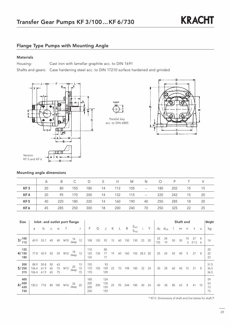
Flange type pumps with mounting angle . . . . . . . . . . . . . . . . . . . . . . . . . . . . . . . . . . 23
Characteristic curves . . . . . . . . . . . . . . . . . . . . . . . . . . . . . . . . . . . . . . . . . . . . . . . . . 24 – 26
Contents
3
Transfer Gear Pumps KF 3/100...KF 6/730
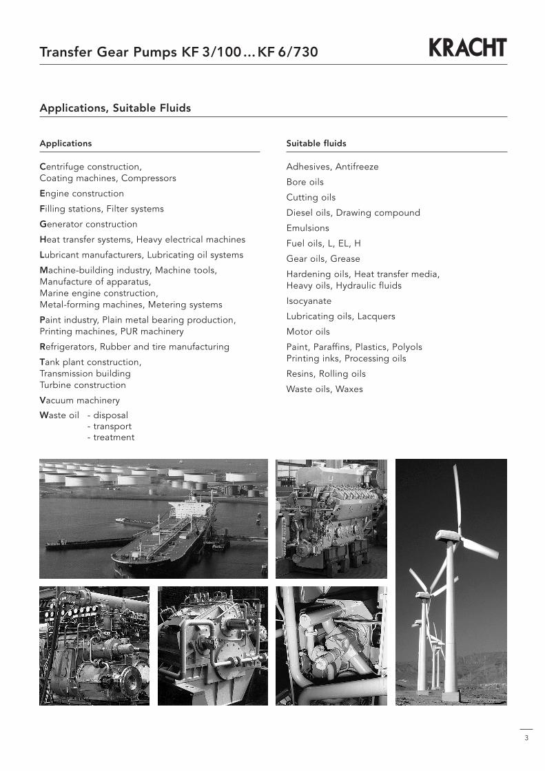
Applications, Suitable Fluids
Applications
Centrifuge construction,Coating machines, Compressors
Engine construction
Filling stations, Filter systems
Generator construction
Heat transfer systems, Heavy electrical machines
Lubricant manufacturers, Lubricating oil systems
Machine-building industry, Machine tools,Manufacture of apparatus,Marine engine construction,Metal-forming machines, Metering systems
Paint industry, Plain metal bearing production,Printing machines, PUR machinery
Refrigerators, Rubber and tire manufacturing
Tank plant construction,Transmission buildingTurbine construction
Vacuum machinery
Waste oil - disposal- transport- treatment
Suitable fluids
Adhesives, Antifreeze
Bore oils
Cutting oils
Diesel oils, Drawing compound
Emulsions
Fuel oils, L, EL, H
Gear oils, Grease
Hardening oils, Heat transfer media,Heavy oils, Hydraulic fluids
Isocyanate
Lubricating oils, Lacquers
Motor oils
Paint, Paraffins, Plastics, PolyolsPrinting inks, Processing oils
Resins, Rolling oils
Waste oils, Waxes

4
Transfer Gear Pumps KF 3/100...KF 6/730
Function
KF gear pumps are used for pumping a wide variety of fluids.
KF gear pumps are distinguished especially by theirwide range of variants which are assembled as requiredon the modular principle and also permit subsequentupgrade.
The pumps are also suitable for media with low lubricating properties.
The standard housing sections are of grey cast iron. The gear units are manufactured from high strength case hardening steel, hardened and mounted in specialmulticompound plain bearing bushes.
The standard drive shaft is sealed by rotary shaft liptype seal.
All pump sizes incorporate helical tooth system. This feature, combined with special gear geometry, results in extremely low noise levels and reduced pressure pulsation.
Working Notes
• The fluids should ensure a certain minimumlubricating properties, should not contain solids andshould be chemically compatible.
• Avoid dry operation.
• The pumps may only be operated in the specifieddirection of rotation, as otherwise the shaft seal willbe destroyed.
• In order to prevent excessive overpressure, a safetyvalve should be provided in the system or on thepump.
• The pressure relief valve attached to the pumpmay only be used as safety valve for short-termoperation.
• A separate pressure relief valve with return line tothe reservoir must be foreseen, if a partial dischargeflow has to be drained over a prolonged period.
Plain bearing bush
End cover
Housing Driven shaft pinion
Shaft end seal
Drive shaft end
Outboard bearing
Flange mounting cover
Gear
Construction
Transfer Gear Pumps KF 3/100...KF 6/730
5
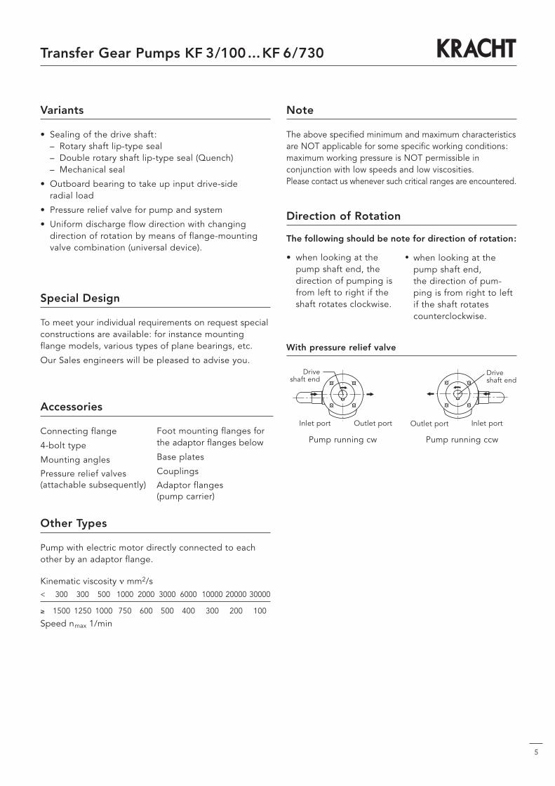
Variants
• Sealing of the drive shaft:– Rotary shaft lip-type seal– Double rotary shaft lip-type seal (Quench)– Mechanical seal
• Outboard bearing to take up input drive-sideradial load
• Pressure relief valve for pump and system
• Uniform discharge flow direction with changingdirection of rotation by means of flange-mountingvalve combination (universal device).
Note
The above specified minimum and maximum characteristicsare NOT applicable for some specific working conditions:maximum working pressure is NOT permissible in conjunction with low speeds and low viscosities.Please contact us whenever such critical ranges are encountered.
Kinematic viscosity ν mm2/s< 300 300 500 1000 2000 3000 6000 10000 20000 30000
≥ 1500 1250 1000 750 600 500 400 300 200 100
Speed nmax 1/min
Other Types
Pump with electric motor directly connected to eachother by an adaptor flange.
Pump running ccw
Outlet port
Pump running cw
Inlet portOutlet port
• when looking at thepump shaft end, thedirection of pumping isfrom left to right if theshaft rotates clockwise.
Direction of Rotation
The following should be note for direction of rotation:
With pressure relief valve
Drive shaft end
Driveshaft end
Inlet port
• when looking at thepump shaft end,the direction of pum-ping is from right to leftif the shaft rotatescounterclockwise.
Special Design
To meet your individual requirements on request specialconstructions are available: for instance mountingflange models, various types of plane bearings, etc.
Our Sales engineers will be pleased to advise you.
Accessories
Connecting flange
4-bolt type
Mounting angles
Pressure relief valves(attachable subsequently)
Foot mounting flanges forthe adaptor flanges below
Base plates
Couplings
Adaptor flanges(pump carrier)
6
Transfer Gear Pumps KF 3/100...KF 6/730
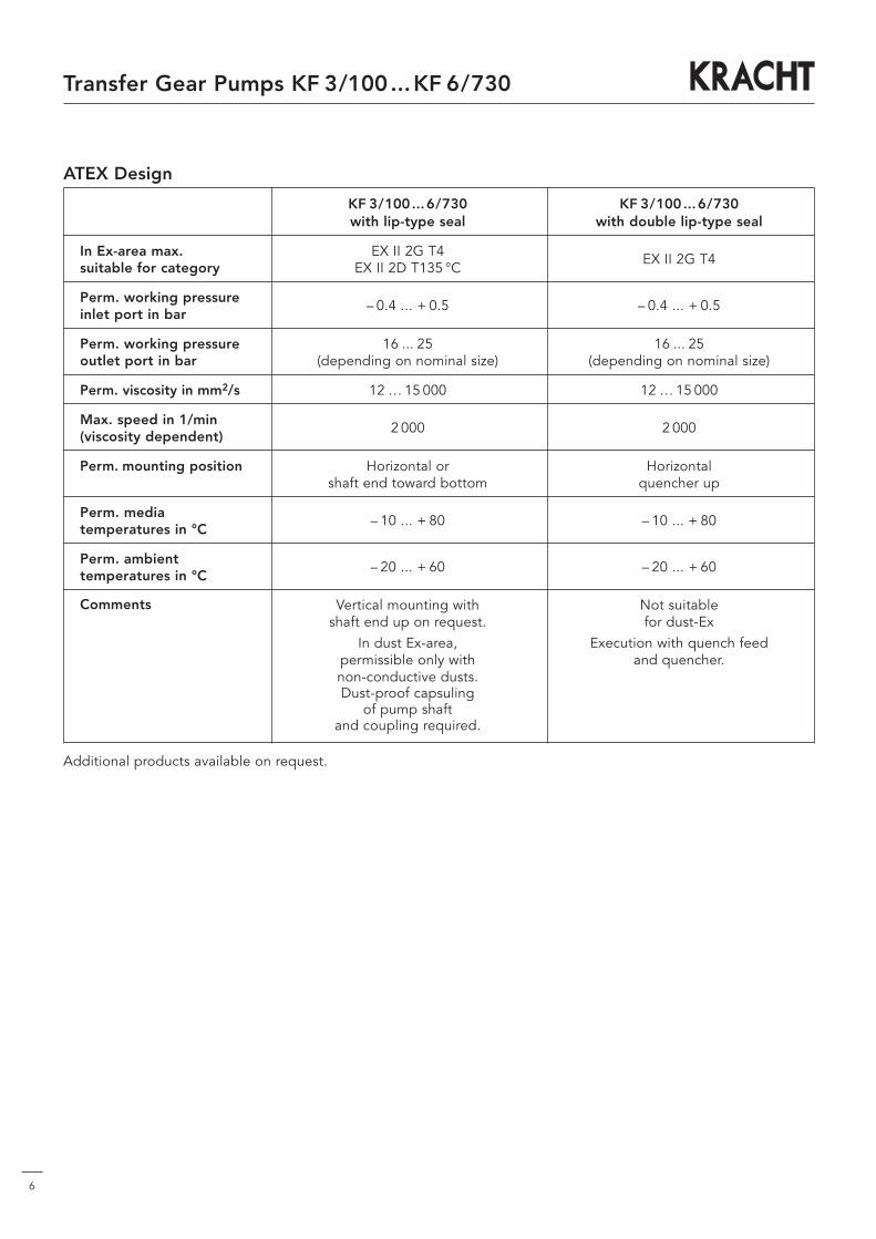
ATEX Design
KF 3/100...6/730 KF 3/100...6/730with lip-type seal with double lip-type seal
In Ex-area max. EX II 2G T4 EX II 2G T4suitable for category EX II 2D T135 °C
Perm. working pressure – 0.4 ... + 0.5 – 0.4 ... + 0.5inlet port in bar
Perm. working pressure 16 ... 25 16 ... 25outlet port in bar (depending on nominal size) (depending on nominal size)
Perm. viscosity in mm2/s 12 … 15 000 12 … 15 000
Max. speed in 1/min 2 000 2 000(viscosity dependent)
Perm. mounting position Horizontal or Horizontalshaft end toward bottom quencher up
Perm. media – 10 ... + 80 – 10 ... + 80temperatures in °C
Perm. ambient – 20 ... + 60 – 20 ... + 60temperatures in °C
Comments
Additional products available on request.
Not suitablefor dust-Ex
Execution with quench feed and quencher.
Vertical mounting with shaft end up on request.
In dust Ex-area,permissible only with non-conductive dusts.Dust-proof capsuling
of pump shaft and coupling required.

7
Transfer Gear Pumps KF 3/100...KF 6/730
Materials
Type of material Housing /Cover Gears Bearing Shaft end sealing O-Ringand sealing*
0DP1/7DP1 EN-GJL-250 NBR NBR0DP2/7DP2 (GG 25) Case hardening P 10 FKM FKM0VP1/7VP1 EN-GJS-400-15 steel NBR NBR0VP2/7VP2 (GGG 40) (1.7139) FKM FKM
* See nameplate on the pump: KF...
Characteristics
Mounting position Optional (for exeptions refer to Universal Arrangement)
Direction of rotation clockwise or counterclockwiseclockwise and counterclockwise
Mounting flange- and angle foot type
flanged pipe connections, 4-bolt type (straight flangePipe connection couplings, welding connectors, in addition Intermediate
flange heatable), threaded ports
pe min-- 0.4 bar (Vacuum) for short time duty e.g. when starting:down to -- 0.6 bar are permissible, observe the limitationof pe min for pumps with Universal Arrangement
standard 0.5 bar for PTFE rotary shaft lip type sealspe max 1.0 bar for NBR- and FKM rotary shaft lip type seals
10 bar for mechanical seals
Working pressures 309pe min -- 0.9 bar
Inlet port pe max 0.2 bar
196pe min -- 0.4 bar, Starting condition -- 0.6 bar
pe max 25 bar
197pe min -- 0.4 bar, Starting condition -- 0.6 bar
pe max 1 bar
Working pressure Outlet port Pn 25 bar*
nmin 200 1/min
Speed nmax 2000 1/mnThe permissible max. speed depends upon the viscosityof the medium operated acc. to the table on page 10
νmin 12 mm2/sViscosity
νmax 15000 mm2/s (Viscosities other than within this range on request)
Weight kg see dimensional sheets
ϑm min -- 10 °C
ϑm max 90 °C for NBR rotary shaft lip type seals
Fluid temperature 150 °C for FKM rotary shaft lip type seals
and mechanical seals SAVGG200 °C for PTFE rotary shaft lipv type seals200 °C for mechanical Seals SATGG or ord. code refer to p.11
Ambient temperatureϑm min -- 20 °C
ϑm max +60 °C
Low temperature on request
Filter Filter fineness ≤ 60 µm
* higher pressures only with prior consent from Kracht GmbH
Transfer Gear Pumps KF 3/100...KF 6/730 noise optimized
8
General
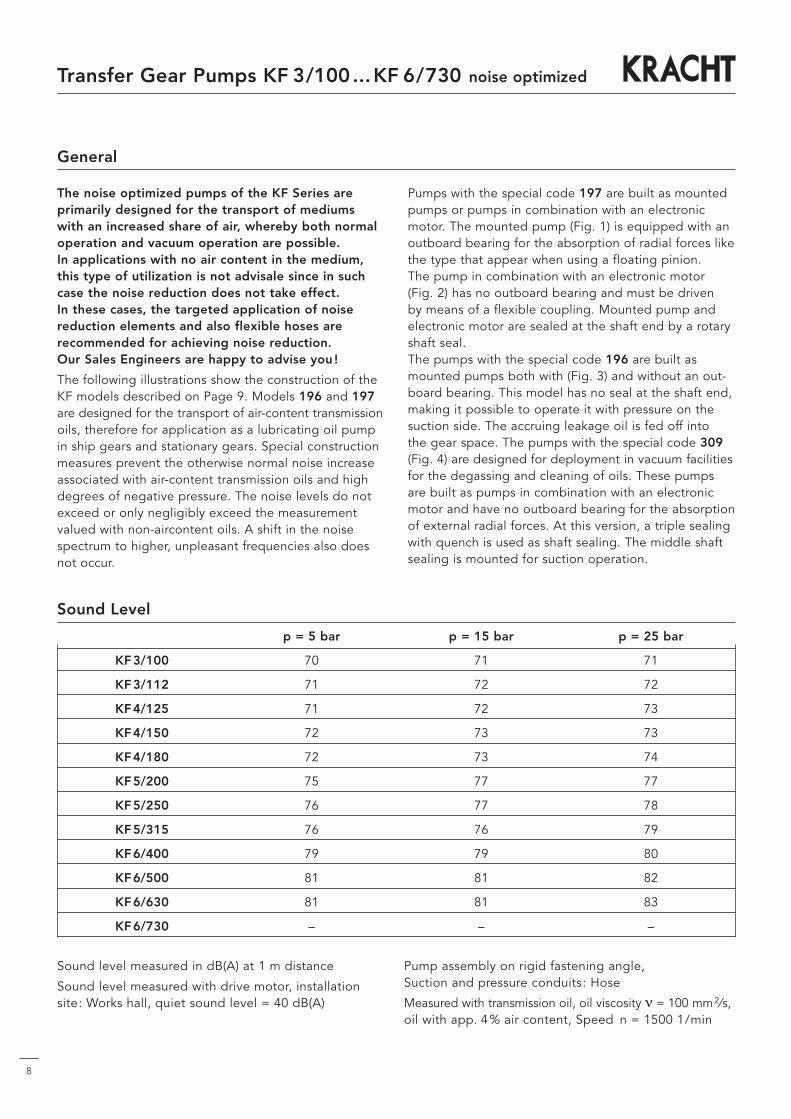
The noise optimized pumps of the KF Series areprimarily designed for the transport of mediumswith an increased share of air, whereby both normaloperation and vacuum operation are possible.In applications with no air content in the medium,this type of utilization is not advisale since in suchcase the noise reduction does not take effect.In these cases, the targeted application of noisereduction elements and also flexible hoses arerecommended for achieving noise reduction.Our Sales Engineers are happy to advise you !
The following illustrations show the construction of theKF models described on Page 9. Models 196 and 197are designed for the transport of air-content transmissionoils, therefore for application as a lubricating oil pumpin ship gears and stationary gears. Special constructionmeasures prevent the otherwise normal noise increaseassociated with air-content transmission oils and highdegrees of negative pressure. The noise levels do notexceed or only negligibly exceed the measurementvalued with non-aircontent oils. A shift in the noisespectrum to higher, unpleasant frequencies also doesnot occur.
Pumps with the special code 197 are built as mountedpumps or pumps in combination with an electronicmotor. The mounted pump (Fig. 1) is equipped with anoutboard bearing for the absorption of radial forces likethe type that appear when using a floating pinion.The pump in combination with an electronic motor(Fig. 2) has no outboard bearing and must be drivenby means of a flexible coupling. Mounted pump andelectronic motor are sealed at the shaft end by a rotaryshaft seal.The pumps with the special code 196 are built asmounted pumps both with (Fig. 3) and without an out-board bearing. This model has no seal at the shaft end,making it possible to operate it with pressure on thesuction side. The accruing leakage oil is fed off intothe gear space. The pumps with the special code 309(Fig. 4) are designed for deployment in vacuum facilitiesfor the degassing and cleaning of oils. These pumpsare built as pumps in combination with an electronicmotor and have no outboard bearing for the absorptionof external radial forces. At this version, a triple sealingwith quench is used as shaft sealing. The middle shaftsealing is mounted for suction operation.
Sound Level
p = 5 bar p = 15 bar p = 25 bar
KF3/100 70 71 71
KF3/112 71 72 72
KF4/125 71 72 73
KF4/150 72 73 73
KF4/180 72 73 74
KF5/200 75 77 77
KF5/250 76 77 78
KF5/315 76 76 79
KF6/400 79 79 80
KF6/500 81 81 82
KF6/630 81 81 83
KF6/730 – – –
Sound level measured in dB(A) at 1 m distance
Sound level measured with drive motor, installationsite: Works hall, quiet sound level = 40 dB(A)
Pump assembly on rigid fastening angle,Suction and pressure conduits: Hose
Measured with transmission oil, oil viscosity ν = 100 mm2⁄s,oil with app. 4% air content, Speed n = 1500 1/min

Transfer Gear Pumps KF 3/100...KF 6/730 noise optimized
9
Construction Noise Optimized Design
Fig. 4 Pump without outboard bearing,special code 309 (Vacuum design)
1 Housing2 Flange cover3 Driving shaft4 Gears5 End cover6 Bearing bush7 Shaft end sealing8 O-Ring9 Connection pipe
Fig. 1 Pump with outboard bearing,special code 197 (with Shaft end seal)
1 Housing2 Flange cover3 Driving shaft4 Gears5 End cover6 Bearing bush7 Shaft end sealing8 O-Ring9 Outboard bearing
Fig. 2 Pump without outboard bearing,special code 197 (with Shaft end seal)
1 Housing2 Flange cover3 Driving shaft4 Gears5 End cover6 Bearing bush7 Shaft end sealing8 O-Ring
Fig. 3 Pump with outboard bearing,special code 196 (without Shaft end seal)
1 Housing2 Flange cover3 Driving shaft4 Gears5 End cover6 Bearing bush7 Shaft end sealing8 O-Ring9 Outboard bearing
Note: Dimensions conformable standard Transfer Gear Pumps KF.

10
Transfer Gear Pumps KF 3/100...KF 6/730
The dispersion of discharge flow Q as specified in the above table may be: Q + 2.5 % up to -- 5 %.At viscosities of ν <30 mm2/s reduction of the discharge flow Q. At viscosities of ν >300 mm2/s, the speed must be reduced.The drive motor output must be selected 20 % higher than the data for P as specified in the above table.For viscosities of ν > 100 mm2/s the power input must be increased. The values count to oils without share of air.
NominalWorking pressure pb in barsize
Working pressure pb in bar
2 4 6 8 10 12 14 16 18 20 22 25 2 4 6 8 10 12 14 16 18 20 22 25142 141 140 139 138 137 136 135 134 133 132 130 1.2 1.7 2.2 2.7 3.2 3.7 4.2 4.7 5.2 5.7 6.2 6.9157 156 155 154 153 152 151 150 149 148 147 145 1.4 2.0 2.6 3.1 3.7 4.3 4.7 5.3 5.8 6.4 7.0 7.8180 178 176 175 173 171 169 168 166 164 162 160 1.6 2.2 2.8 3.4 4.0 4.6 5.2 5.8 6.4 7.0 7.6 8.5215 213 212 210 208 206 205 203 201 199 197 195 1.9 2.6 3.3 4.0 4.8 5.5 6.2 7.0 7.7 8.4 9.2 10.6262 260 258 257 255 254 253 251 250 248 247 245 2.2 3.0 3.9 4.8 5.7 6.6 7.5 8.4 9.3 10.2 11.0 12.4285 283 281 279 278 276 274 273 271 269 267 265 2.4 3.4 4.4 5.4 6.5 7.5 8.6 9.6 10.7 11.7 12.7 14.2356 354 351 349 347 344 342 340 338 335 3.0 4.3 5.5 6.8 8.1 9.4 10.7 12.0 13.3 14.6450 448 447 446 444 443 442 441 3.7 5.3 6.9 8.6 10.2 11.7 13.4 15.0575 572 569 566 563 560 557 554 551 548 545 540 5.8 7.7 9.6 11.6 13.5 15.5 17.5 19.5 21.4 23.3 25.3 28.3715 711 707 703 699 695 691 688 685 681 7.3 9.8 12.3 14.7 17.2 19.6 22.0 24.5 27.0 29.4895 891 887 883 878 874 870 865 9.3 12.0 15.0 18.0 21.0 24.0 27.0 30.0
1060010470103401022010080 993 978 11.0 14.8 18.6 22.4 26.2 30.0 33.7
Discharge flow Q in l/min Power input required P in kW
Size Nominal Geometrical. Working Maximum Speed Perm. forces Momentdisplacement displace- pressure pressure range (n = 1450 1/min) of inertia
volumen (without coupling x10-4)Vg pb pmax nmin nmax Fradial Faxial J
cm3 bar bar 1/min 1/min N N kgm2
3 /100 100.8 25 30 200 2000 1500 200 6.75112 112.6 25 25 200 2000 1500 200 7.50125 129 25 40 200 2000 1500 200 13.75
4 / 150 153 25 30 200 2000 1500 200 16,00180 184 25 25 200 2000 1500 200 19.25200 204 25 30 200 2000 2000 300 27.50
5 / 250 255 20 25 200 2000 2000 300 34.50315 321 16 20 200 2000 2000 300 43,00400 405 25 30 200 2000 3000 500 105,000
6 /500 505 20 25 200 2000 3000 500 130,000630 629 16 20 200 2000 3000 500 160,000730 730 14 16 200 1500 3000 500 –
Note: Working pressure pb = permissible continuous pressureMaximum pressure pmax = only applicable to the operation with mineral oils at speed
> 700 1/min and viscosities ν = 30 mm2/s up to 1000 mm2/sPermissible forces only applicable to the types fitted with outboard bearing Fradial to the middle of the shaft end.
3/ 100112125
4/ 150180200
5/ 250315400
6/ 500630730
Technical Data
Version standard – Speed n = 1450 1/min
NominalWorking pressure pb in barsize
Working pressure pb in bar
2 4 6 8 10 12 14 16 18 20 22 25 2 4 6 8 10 12 14 16 18 20 22 25138 137 136 135 134 133 132 131 130 129 128 126 1.2 1.7 2.2 2.7 3.2 3.7 4.2 4.7 5.2 5.7 6.2 6.9152 151 150 149 148 147 146 146 145 144 143 141 1.4 2.0 2.6 3.1 3.7 4.3 4.7 5.3 5.8 6.4 7.0 7.8175 173 171 170 168 166 164 163 161 159 157 155 1.6 2.2 2.8 3.4 4.0 4.6 5.2 5.8 6.4 7.0 7.6 8.5209 207 206 204 202 200 199 197 195 193 191 189 1.9 2.6 3.3 4.0 4.8 5.5 6.2 7.0 7.7 8.4 9.2 10.6254 252 250 249 247 246 245 243 243 241 240 238 2.2 3.0 3.9 4.8 5.7 6.6 7.5 8.4 9.3 10.2 11.0 12.4276 275 273 271 270 268 266 265 263 261 259 257 2.4 3.4 4.4 5.4 6.5 7.5 8.6 9.6 10.7 11.7 12.7 14.2345 343 340 339 337 334 332 330 328 325 3.0 4.3 5.5 6.8 8.1 9.4 10.7 12.0 13.3 14.6437 435 434 433 431 430 429 428 3.7 5.3 6.9 8.6 10.2 11.7 13.4 15.0558 555 552 549 546 543 540 537 534 532 529 524 5.8 7.7 9.6 11.6 13.5 15.5 17.5 19.5 21.4 23.3 25.3 28.3694 690 686 682 678 674 670 667 664 661 7.3 9.8 12.3 14.7 17.2 19.6 22.0 24.5 27.0 29.4868 864 860 857 852 848 844 839 9.3 12.0 15.0 18.0 21.0 24.0 27.0 30.0
102801016010030 991 978 963 949 11.0 14.8 18.6 22.4 26.2 30.0 33.7
Discharge flow Q in l/min Power input required P in kW
3/ 100112125
4/ 150180200
5/ 250315400
6/ 500630730
Version noise optimized – Speed n = 1450 1/min
Discharge flow / Input power
11
Transfer Gear Pumps KF 3/100...KF 6/730
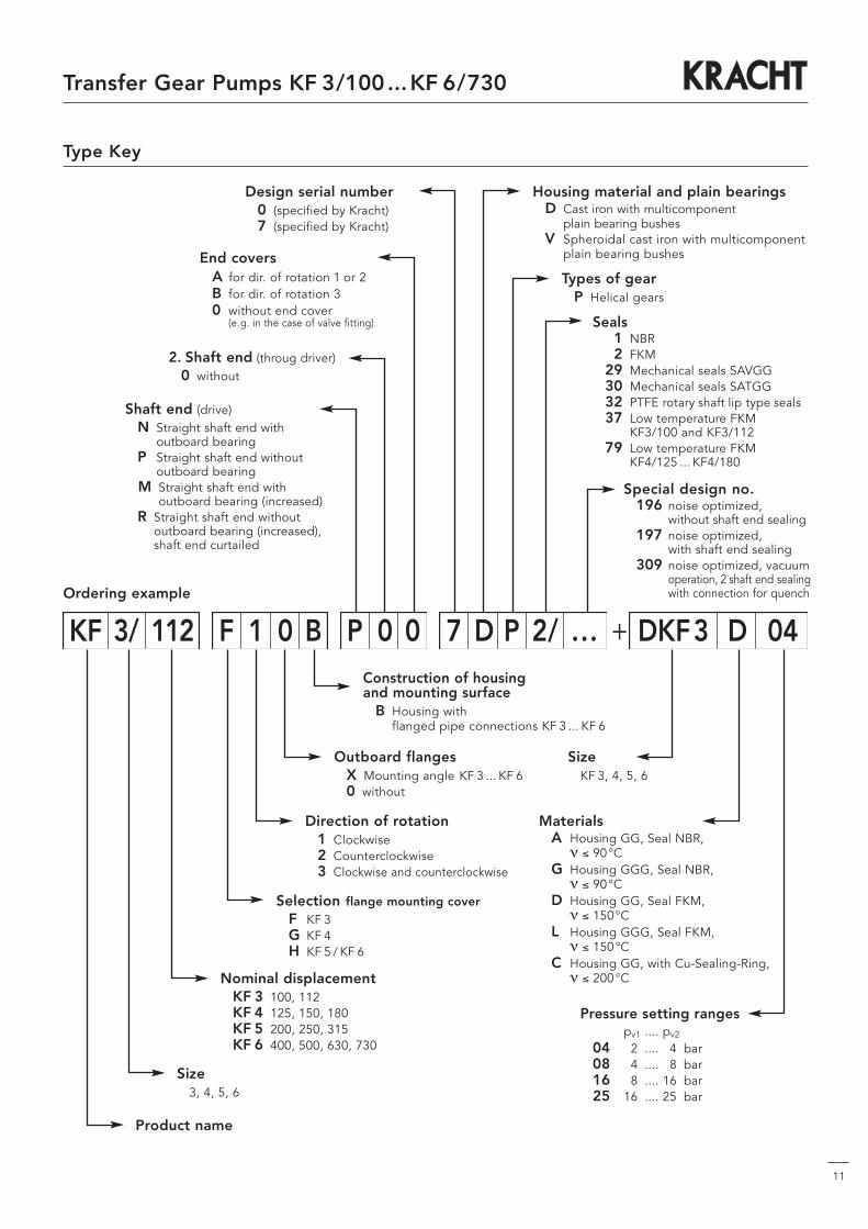
Type Key
Ordering example
Size3, 4, 5, 6
Product name
Pressure setting rangespv1 .... pv2
04 2 .... 4 bar08 4 .... 8 bar16 8 .... 16 bar25 16 .... 25 bar
SizeKF 3, 4, 5, 6
Seals1 NBR2 FKM
29 Mechanical seals SAVGG30 Mechanical seals SATGG32 PTFE rotary shaft lip type seals37 Low temperature FKM
KF3/100 and KF3/11279 Low temperature FKM
KF4/125 ... KF4/180
Types of gearP Helical gears
Housing material and plain bearingsD Cast iron with multicomponent
plain bearing bushesV Spheroidal cast iron with multicomponent
plain bearing bushes
Design serial number0 (specified by Kracht)7 (specified by Kracht)
End coversA for dir. of rotation 1 or 2B for dir. of rotation 30 without end cover
(e.g. in the case of valve fitting)
2. Shaft end (throug driver)0 without
Shaft end (drive)N Straight shaft end with
outboard bearingP Straight shaft end without
outboard bearingM Straight shaft end with
outboard bearing (increased)R Straight shaft end without
outboard bearing (increased),shaft end curtailed
Construction of housingand mounting surface
B Housing with flanged pipe connections KF 3 ... KF 6
Outboard flangesX Mounting angle KF 3 ... KF 60 without
Direction of rotation1 Clockwise2 Counterclockwise3 Clockwise and counterclockwise
Selection flange mounting coverF KF 3G KF 4H KF 5 / KF 6
Nominal displacementKF 3 100, 112KF 4 125, 150, 180KF 5 200, 250, 315KF 6 400, 500, 630, 730
Special design no.196 noise optimized,
without shaft end sealing197 noise optimized,
with shaft end sealing309 noise optimized, vacuum
operation, 2 shaft end sealingwith connection for quench
MaterialsA Housing GG, Seal NBR,
ν ≤ 90°CG Housing GGG, Seal NBR,
ν ≤ 90°CD Housing GG, Seal FKM,
ν ≤ 150°CL Housing GGG, Seal FKM,
ν ≤ 150°CC Housing GG, with Cu-Sealing-Ring,
ν ≤ 200°C
KF 3/ 112 F 1 0 B P 0 0 7 D P 2/ ... + DKF3 D 04

12
Flange Type Pumps
Transfer Gear Pumps KF 3/100...KF 6/730
Parallel keyacc. to
DIN 6885
Size Inlet- and outlet port Shaft endpipe thread
a b c e f r C D E F G J K L M R Sh6 i y d1 dk6 l m n t u kg
3/10069.9 35.7 40 40 M10 16 12 150 180 14 108 120 92 15 60 5 130 130 23 20
25 24 50 30 10 27 813.5
112 deep *20 19 50 30 5 21.5 6
12518
110 80 18.54/150 77.8 42.9 50 50 M12 deep 12 185 220 18 125 130 77 19 60 8 160 150 28.3 20 25 24 50 40 5 27 8 20f
180 135 77 21f
200 88.9 50.8 55 6320
13 155 93 28f5/250 106.4 61.9 65 75 M12 deep 15 215 250 18 170 150 109 22 70 8 198 180 32 24 30 28 60 40 10 31 8 33f
315 106.4 61.9 65 75 15 170 109 33f
400 180 124 51f
6/ 500130.2 77.8 80 100 M16 32 20 215 250 18
200200
12625 95 8 244 180 40 24 40 38 80 63 8 41 10
55f630 deep 200 159 65f730 200 159 65f
* KF3: Dimensions of shaft end line below for shaft P
KF 3 / . F 0B N 0 A 7DPP B V
123
KF 4 / . G 0B N 0 A 7DPP B V
123
12
32
KF 5 / . H 0B N 0 A 0DPP B V
123
12
32
KF 6 / . H 0B N 0 A 7DPP B V
123
12
32
Ordering code12
32
Weight

13
Transfer Gear Pumps KF 3/100...KF 6/730
Parallel keyacc. to
DIN 6885
Flange Type Pumps with Pressure Relief Valve
Size Inlet- and outlet port Shaft end Weightpipe thread
a b c e f r C D E F G J1 K L M R Sh6 Y i y1 d1 dk6 l m n t u kg
3/ 10069.9 35.7 40 40 M10 16 12 150 180 14 108 120 137 15 60 5 130 130 160 23 65
25 24 50 30 10 27 815
s112 deep *20 19 50 30 5 21.5 6
12518
110 132 20.04/ 150 77.8 42.9 50 50 M12 deep 12 185 220 18 125 130 129 19 60 8 160 150 171 28.3 72 25 24 50 40 5 27 8 21.5
180 135 129 21.5
200 88.9 50.8 55 6320
13 155 149 30s5/ 250 106.4 61.9 65 75 M12 deep 15 215 250 18 170 150 165 22 70 8 198 180 196 32 80 30 28 60 40 10 31 8 35s
315 106.4 61.9 65 75 15 170 165 35s
400 180 217 59s
6/ 500130.2 77.8 80 100 M16 32 20 215 250 18
200200
21925 95 8 244 180 238 40 117 40 38 80 63 8 41 10
63s630 deep 200 252 73s730 200 252 73s
* KF3: Dimensions of shaft end line below for shaft P
KF 3 / . F 0B N 00 7DP + DKF 3 •P V12
12
32
ADCG
KF 4 / . G 0B N 00 7DP + DKF 4 •P V12
12
32
ADCG
KF 5 / . H 0B N 00 0DP + DKF 5 •P V12
12
32
ADCG
KF 6 / . H 0B N 00 7DP + DKF 6 •P V12
12
32
ADCG
Ordering code
14
Transfer Gear Pumps KF 3/100...KF 6/730
Parallel keyacc. to
DIN 6885
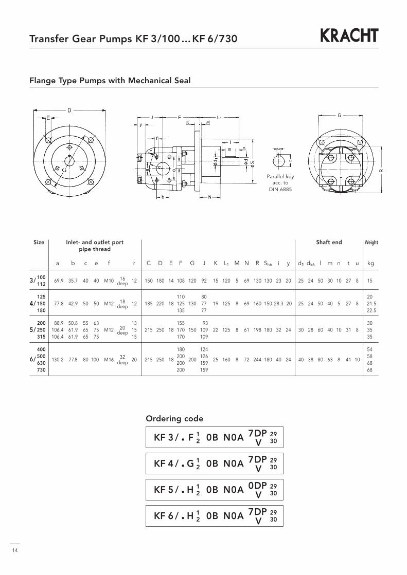
Flange Type Pumps with Mechanical Seal
Size Inlet- and outlet port Shaft end Weightpipe thread
a b c e f r C D E F G J K L1 M N R Sh6 i y d1 dk6 l m n t u kg
3/ 10069.9 35.7 40 40 M10 16 12 150 180 14 108 120 92 15 120 5 69 130 130 23 20 25 24 50 30 10 27 8 15s
112 deep
12518
110 80 20s4/ 150 77.8 42.9 50 50 M12 deep 12 185 220 18 125 130 77 19 125 8 69 160 150 28.3 20 25 24 50 40 5 27 8 21.5
180 135 77 22.5
200 88.9 50.8 55 6320
13 155 93 30s5/ 250 106.4 61.9 65 75 M12 deep 15 215 250 18 170 150 109 22 125 8 61 198 180 32 24 30 28 60 40 10 31 8 35s
315 106.4 61.9 65 75 15 170 109 35s
400 180 124 54s
6/ 500130.2 77.8 80 1000 M16 32 20 215 250 18
200200
12625 160 8 72 244 180 40 24 40 38 80 63 8 41 10
58s630 deep 200 159 68s730 200 159 68s
KF 3 / . F 0B N0A 7DP12
2930
KF 4 / . G 0B N0A 7DP12
2930
KF 5 / . H 0B N0A 0DP12
2930
KF 6 / . H 0B N0A 7DP12
2930
Ordering code
V
V
V
V
15
Transfer Gear Pumps KF 3/100...KF 6/730
Parallel keyacc. to
DIN 6885
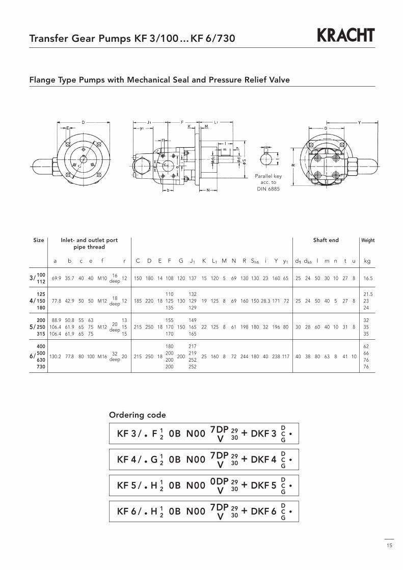
Flange Type Pumps with Mechanical Seal and Pressure Relief Valve
Size Inlet- and outlet port Shaft end Weightpipe thread
a b c e f r C D E F G J1 K L1 M N R Sh6 i Y y1 d1 dk6 l m n t u kg
3/ 10069.9 35.7 40 40 M10 16 12 150 180 14 108 120 137 15 120 5 69 130 130 23 160 65 25 24 50 30 10 27 8 16.5
112 deep
12518
110 132 21.54/ 150 77.8 42.9 50 50 M12 deep 12 185 220 18 125 130 129 19 125 8 69 160 150 28.3 171 72 25 24 50 40 5 27 8 23_
180 135 129 24_
200 88.9 50.8 55 6320
13 155 149 32_5/ 250 106.4 61.9 65 75 M12 deep 15 215 250 18 170 150 165 22 125 8 61 198 180 32 196 80 30 28 60 40 10 31 8 35_
315 106.4 61.9 65 75 15 170 165 35_
400 180 217 62_
6/ 500130.2 77.8 80 100 M16 32 20 215 250 18
200200
21925 160 8 72 244 180 40 238 117 40 38 80 63 8 41 10
66_630 deep 200 252 76_730 200 252 76_
KF 3 / . F 0B N00 7DP + DKF 3 •12
2930
DCG
KF 4 / . G 0B N00 7DP + DKF 4 •12
2930
DCG
KF 5 / . H 0B N00 0DP + DKF 5 •12
2930
DCG
KF 6 / . H 0B N00 7DP + DKF 6 •12
2930
DCG
Ordering code
V
V
V
V

16
Transfer Gear Pumps KF 3/100...KF 6/730
Pumps with electric motor
1
2
1
Ø C
Ø E
Ø A
23
L
136
L
Ø D
k
s
w
10892
e
a
B
Ø g
x
p
120
160
f
b
h
c
When ordering a flange type pump with electric motor please specifythe rated voltage, the frequency, the speed and the enclose requested
Mounting arrangement: IM B35 (IM V15; IM V36)
Size Power Speed Bell Coupling Totalhousing weight * L1 L2
kW 1/min kg
100 L4A 2.2 1420 37 633 677100 L4B 3.0 1430 Z3/250/135 RA28-Z35/19-Z35/28 40 633 677112 M4B 4.0 1440 47 670 714
132 S4C 5.5 1450 Z3/300/180 RA38-Z45/19-Z45/38 58 748 792132 M4B 7.5 1450 79 779 823
160 M4B 11.0 1450 Z3/350/204 RA38/45-Z45/19-Z45/42 94 870 914160 L4A 15.0 1450 108
180 M4B 18.5 1450 Z3/350/204 RA42/55-Z50/19-Z50/48 138 923 967180 L4B 22.0 1455 146
* Additional weight for units with pressure relief valve 1.5 kg
Size Ø A B Ø C Ø D Ø E a b c e f g h k p s w1 x
100 250 135 215 190 14 140 160 12 172 192 213 100 298 232 12 63 96112 190 224 234 112 335 252 70 106
132 S 300 180 265 234 14 140 216 12 187 264 265 132 358 283 12 89 112132 M 178 218 266 298 399 303 118
160 M 350 204 300 260 17 210 254 18 306 306 323 160 466 341 15 108 114160 L 254
180 M 350 204 300 260 17 241 279 22 343 344 370 180 519 387 15 121 136180 L 279
The values specified in the table above relate after DIN 42 G 73 / G 77(Motors from other manufactures are available on request)
Motor Pump Assemblies KF 3
17
Transfer Gear Pumps KF 3/100...KF 6/730
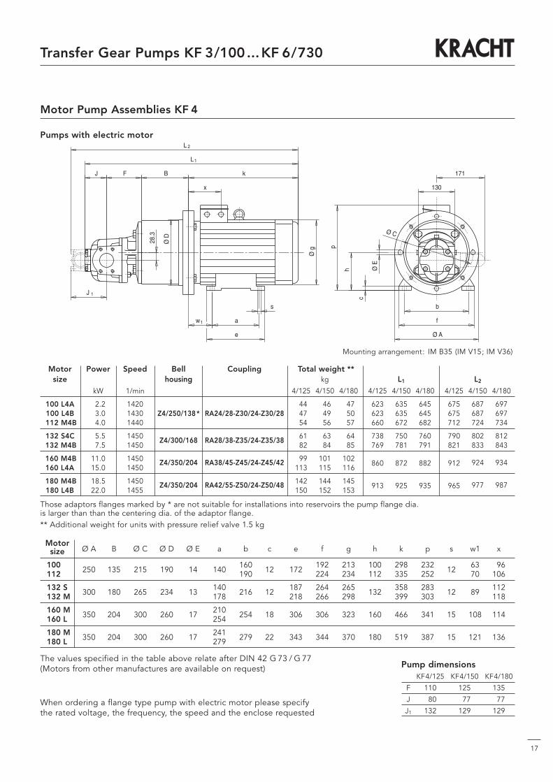
Pumps with electric motor
Motor Pump Assemblies KF 4
2
1
1
1
c
L
L
J
kØ
D
w
28.3
J F B
e
a
Ø g
x
s
Ø C
Ø E
Ø A
171
130
f
b
p
h
When ordering a flange type pump with electric motor please specifythe rated voltage, the frequency, the speed and the enclose requested
Mounting arrangement: IM B35 (IM V15; IM V36)
Motorsize Ø A B Ø C Ø D Ø E a b c e f g h k p s w1 x
100 250 135 215 190 14 140 160 12 172 192 213 100 298 232 12 63 96112 190 224 234 112 335 252 70 106
132 S 300 180 265 234 13 140 216 12 187 264 265 132 358 283 12 89 112132 M 178 218 266 298 399 303 118
160 M 350 204 300 260 17 210 254 18 306 306 323 160 466 341 15 108 114160 L 254
180 M 350 204 300 260 17 241 279 22 343 344 370 180 519 387 15 121 136180 L 279
The values specified in the table above relate after DIN 42 G 73 / G 77(Motors from other manufactures are available on request)
Motor Power Speed Bell Coupling Total weight **size housing kg L1 L2
kW 1/min 4/125 4/150 4/180 4/125 4/150 4/180 4/125 4/150 4/180
100 L4A 2.2 1420 44 46 47 623 635 645 675 687 697100 L4B 3.0 1430 Z4/250/138* RA24/28-Z30/24-Z30/28 47 49 50 623 635 645 675 687 697112 M4B 4.0 1440 54 56 57 660 672 682 712 724 734
132 S4C 5.5 1450Z4/300/168 RA28/38-Z35/24-Z35/38
61 63 64 738 750 760 790 802 812132 M4B 7.5 1450 82 84 85 769 781 791 821 833 843
160 M4B 11.0 1450 Z4/350/204 RA38/45-Z45/24-Z45/42 99 101 102860 872 882 912 924 934
160 L4A 15.0 1450 113 115 116
180 M4B 18.5 1450 Z4/350/204 RA42/55-Z50/24-Z50/48 142 144 145913 925 935 965 977 987
180 L4B 22.0 1455 150 152 153
Those adaptors flanges marked by * are not suitable for installations into reservoirs the pump flange dia. is larger than than the centering dia. of the adaptor flange.** Additional weight for units with pressure relief valve 1.5 kg
Pump dimensionsKF4/125 KF4/150 KF4/180
F 110 125 135
J 80 77 77
J1 132 129 129

18
Transfer Gear Pumps KF 3/100...KF 6/730
Ø E
Ø C
c
Ø A
196
150
f
b
p
h
2
1
1
1
L
L
J
k
s
Ø D
J F B
32
w
e
aØ
g
x
When ordering a flange type pump with electric motor please specifythe rated voltage, the frequency, the speed and the enclose requested
Mounting arrangement: IM B35 (IM V15; IM V36)
Motorsize Ø A B Ø C Ø D Ø E a b c e f g h k p s w1 x
132 S 300 195 265 234 14 140 216 12 187 264 265 132 358 283 12 89 112132 M 178 218 266 298 399 303 118
160 M 350 204 300 260 17 210 254 18 306 306 323 160 466 341 15 108 114160 L 254
180 M 350 204 300 260 17 241 279 22 343 344 370 180 519 387 15 121 136180 L 279
The values specified in the table above relate after DIN 42 G 73 / G 77(Motors from other manufactures are available on request)
Motor Power Speed Bell Coupling Total weight **size housing kg L1 L2
kW 1/min 5/200 5/250 5/315 5/200 5/250 5/315 5/200 5/250 5/315
132 S4C 5.5 1450 Z5/300/195* RA42-Z50/28-Z50/38 73 78 78 811 842 842 867 898 898132 M4B 7.5 1450 94 99 99 842 873 873 898 929 929
160 M4B 11.0 1450 Z5/350/204 RA38/45-Z45/28-Z45/42 109 114 114918 949 949 974 1005 1005
160 L4A 15.0 1450 123 128 128
180 M4B 18.5 1450 Z5/350/204 RA42/55-Z50/28-Z50/48 153 158 158971 1002 1002 1027 1058 1058
180 L4B 22.0 1455 161 166 166
Those adaptors flanges marked by * are not suitable for installations into reservoirs the pump flange dia. is larger than than the centering dia. of the adaptor flange.
** Additional weight for units with pressure relief valve 2 kg
Pump dimensionsKF5/200 KF5/250 KF5/315
F 155 170 170
J 93 109 109
J1 149 165 165
Pumps with electric motor
Motor Pump Assemblies KF 5
19
Transfer Gear Pumps KF 3/100...KF 6/730
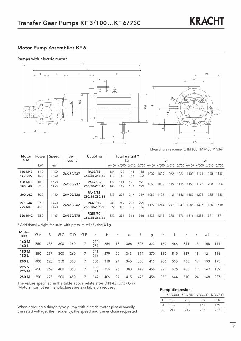
Pumps with electric motor
Ø E
Ø C
Ø A
c
238
200
f
b
p
h
1
2
1
1
s
L
L
k
J
Ø D
J F B
40
w
e
a
Ø g
x
When ordering a flange type pump with electric motor please specifythe rated voltage, the frequency, the speed and the enclose requested
Mounting arrangement: IM B35 (IM V15; IM V36)
Motorsize Ø A B Ø C Ø D Ø E a b c e f g h k p s w1 x
160 M 350 237 300 260 17 210 254 18 306 306 323 160 466 341 15 108 114160 L 254
180 M 350 237 300 260 17 241 279 22 343 344 370 180 519 387 15 121 136180 L 279
200 L 400 228 350 300 17 306 318 24 365 388 415 200 555 435 19 133 175
225 S 450 262 400 350 17 286 356 26 383 442 456 225 626 485 19 149 189225 M 311
250 M 550 275 500 450 17 349 406 27 415 495 456 250 644 510 24 168 207
The values specified in the table above relate after DIN 42 G 73 / G 77(Motors from other manufactures are available on request)
Pump dimensionsKF6/400 KF6/500 KF6/630 KF6/730
F 180 200 200 200
J 124 126 159 159
J1 217 219 252 252
Motor Pump Assemblies KF 6
Motor Power Speed Bell Coupling Total weight *size housing kg L1 L2
kW 1/min 6/400 6/500 6/630 6/730 6/400 6/500 6/630 6/730 6/400 6/500 6/630 6/730
160 M4B 11.0 1450Z6/350/237
RA38/45- 134 138 148 1481007 1029 1062 1062 1100 1122 1155 1155
160 L4A 15.0 1450 Z45/38-Z45/42 148 152 162 162
180 M4B 18.5 1450Z6/350/237
RA42/55- 177 181 191 1911060 1082 1115 1115 1153 1175 1208 1208
180 L4B 22.0 1455 Z50/38-Z50/48 185 189 199 199
200 L4C 30.0 1450 Z6/400/228RA42/55-
235 239 249 249 1087 1109 1142 1142 1180 1202 1235 1235Z50/38-Z50/55
225 S4A 37.0 1460Z6/450/262
RA48/60- 285 289 299 2991192 1214 1247 1247 1285 1307 1340 1340
225 M4C 45.0 1460 Z56/38-Z56/60 322 326 336 336
250 M4C 55.0 1465 Z6/550/275RG55/70-
352 356 366 366 1223 1245 1278 1278 1316 1338 1371 1371Z65/38-Z65/65
* Additional weight for units with pressure relief valve 8 kg

20
Transfer Gear Pumps KF 3/100...KF 6/730
Size Inlet- and outlet port Shaft end Weight Permissiblepipe thread manometric
vacuum at thepump inlet port
a b c e f r A B C D E F G K L M O P Sh6 U i d1 dk6 l m n t u kg Pe in bar
0.363/ 100 77.8 42.9 50 50 M12 12 200 183 150 180 14 93 120 15 60 5 90 140 130 298 23 25 24 50 30 10 27 8 340.35112
125 190 185 95 39 0.344/ 150 77.8 42.9 50 50 M12 12 202 200 185 220 18 110 130 19 60 8 96 146 150 298 28.3s 25 24 50 40 5 27 8 40 0.33
180 212 210 120 41 0.32
200 248 252 122 80 0.385/ 250 106.4 61.9 65 75 M12 15 279 267 215 250 18 137 150 22 70 8 129 199 180 442 32 30 28 60 40 10 31 8 85 0.37
315 279 267 137 85 0.36
400 Inlet port 304 277 147 103 0.376/ 500 130.2 77.8 80 100 M16 20 326 297 215 250 18 167 200 25 95 8 171 241 180 442 40 40 38 80 63 8 41 10 107 0.36
630 Outlet port 359 297 167 117 0.33730 106.4 61.9 65 75 M12 15 359 297 167 117 —
Flange-Type Pumps with Universal Arrangement
KF 3/ . F3 0B N0B 7DP . + KF4U 04
KF 4/ . G3 0B N0B 7DP . + KF4U 05
KF 5/200 H3 0B N0B 0DP . + KF5U 06
KF 5/250 H3 0B N0B 0DP . + KF5U 07
KF 5/315 H3 0B N0B 0DP . + KF5U 07
KF 6/ . H3 0B N0B 7DP . + KF6U 08
Ordering code
V
V
V
V
V
V
Parallel keyacc. to
DIN 6885
Fitting position: horizontal (ill.)

21
Transfer Gear Pumps KF 3/100...KF 6/730
Accessories connecting flange
Welding connector KF 3, KF 4
Ordering example
complete welding connector with gasket and screws for the size KF 4
Size Nom. Screws Nom- Pipe Weightdisplace- DIN size external
ment a b c e f g h m n r s t 912-8.8 Ø kg
KF 3 69.9 35.7 40 9 M10 13 26 45 49 13 15 – M10x25 40 48.3 0.44KF 4 77.8 42.9 50 9 M12 17 26 57 61 13 15 – M12x30 50 60.3 0.63KF 5 / 200 88.9 50.8 55 – M12 16 18 68 77 15 12 12 M12x35 65 76.1 0.86
KF 5 / 250 106.4 61.9 65 – M12 16 18 82 90 15 12 12 M12x35 80 88.9 1.20/ 315KF 6 130.2 77.8 80 – M16 24 24 107j 115.3 20 15 20 M16x50 100j 114.3 2.50
Material: ST 42–2
Material: ST 42–2
2 Pieces Welding Connector KF 4
Material: ST 42–2
Size Screws Weighta b c d e f g h r t DIN 912-8.8 kg
KF3 69.9 35.7 40 G 11⁄2 9 M10 13 26 13 – M10x25 0.44
KF4 77.8 42.9 50 G 2 9 M12 17 26 13 – M12x30 0.63
Welding connector KF 3, KF 4
Ordering example
complete threaded connector with gasket and screws for the size KF 4
2 Pieces Threaded Connector KF 4
Welding connector KF 5, KF 6
Ordering example
complete welding connector with gasket and screws for the size KF 5 / 250
2 Pieces Welding Connector KF 5
Gasket
hex. Socket headcap screw acc. to DIN 912single coil springlock washer acc. to DIN 7980
hex. Socket headcap screw acc. to DIN 912single coil springlock washer acc. to DIN 7980
hex. Socket headcap screw acc. to DIN 912single coil springlock washer acc. to DIN 7980
Gasket
Gasket

Coup- Hub material: Rough Finished bore Dimensions Ordering codeling Aluminium boresize
Weight Moment Part Part Part Part Part Partof inertia 1 2 1 2 1 2
Kg Kgm2 min. min. max. max. l1; l2 E s b L M DH D D1 dh
Version 28 0.39 0.0002 8 – 10 – 28 – 35 20 2.5 15 90 28 65 48 – 30 RA 28-Z 35/..-Z 35/..
A 38 0.82 0.0007 10 – 12 – 38 – 45 24 3 18 114 37 80 66 – 38 RA 38-Z 45/..-Z 45/..
24/28 0.26 0.0001 6 22 8 24 24 28 30 18 2 14 78 24 55 40 48 27 RA 24/28-Z 30/..-Z 30/..
28/38 0.46 0.0003 8 26 10 28 28 38 35 20 2.5 15 90 28 65 48 65 30 RA 28/38-Z 35/..-Z 35/..
38/45 0.89 0.0008 10 36 12 38 38 45 45 24 3 18 114 37 80 66 76 38 RA 38/45-Z 45/..-Z 45/..
Version 38/45 0.89 0.0020 10 36 12 38 38 45 45/70 24 3 18 139 37 80 66 76 38 RA 38/45-Z 45/..-Z 70/..
B 42/55 1.39 0.0018 12 40 14 42 42 55 50 26 3 20 126 40 95 75 94 46 RA 42/55-Z 35/..-Z 50/..
42/55 1.39 0.0050 12 40 14 42 42 55 50/75 26 3 20 151 40 95 75 94 46 RA 42/55-Z 35/..-Z 75/..
48/60 1.86 0.0030 13 46 15 48 48 60 56 28 3.5 21 140 45 105 85 102 51 RA 48/60-Z 35/..-Z 56/..
55/70 7.37 0.0160 18 52 20 55 55 70 65 30 4 22 160 – 120 98 120 60 RG 55/70-Z 65/..-Z 65/..
22
Transfer Gear Pumps KF 3/100...KF 6/730
Type Key KF-Coupling
Working temperature:– 10 °C to + 80 °C(short-time temperature peaks up to + 120 °C are permissible)
Weights as well as moments of inertia relate to the max. bore dia. after final machining – but without key way.Bore finish acc. to ISO – fit, class H7;Key-ways acc. to DIN 6885 / part 1
Ordering example
coupling hub lengt and hub bore
Pump sidecylindrical
Motor sidecylindrical
R .* 38 - Z 45/38 - Z 45/38
Coupling size
.* Hub material
A AL
G GG
Accessories, Couplings
Internal flexible coupling blockof Polyurethane (Vulkollan)Shore hardness: 92°Colour: nature
Version A Version B
Part 1 Part 1 Part 1 Part 2
23
Transfer Gear Pumps KF 3/100...KF 6/730
Size Inlet- and outlet port flange Shaft end Weight
a b c e f r F G J K L R SH7 i Y d1 dk6 l m n t u kgSh6
3/ 10069.9 35.7 40 40 M10 16 12 108 120 92 15 60 130 130 23 20
25 2450 30
10 27 814s
112 deep *200 19 5 21.5 6
125 110 80 20s4/ 150 77.8 42.9 50 50 M12 18 12 125 130 77 19 60 160 150 28.3 20 25 24 50 40 5 27 8 22s
180deep
135 77 23s
200 88.9 50.8 50 63 13 155 93 31.55/ 250 106.4 61.9 65 75 M12 20 15 170 150 109 22 70 198 180 32 24 30 28 60 40 10 31 8 36.5
315 106.4 61.9 65 75deep
15 170 109 36.5
400 180 124 59s
6/ 500130.2 77.8 80 1000 M16 32 20
200200
12625 95 244 180 40 24 40 38 80 63 8 41 10
63s630 deep 200 159 73s730 200 159 73s
* KF 3: Dimensions of shaft end line below for shaft P
Parallel keyacc. to DIN 6885
VersionKF 5 and KF 6
A B C D E H M N O P T V
KF 3 20 80 150 180 14 112 105 – 180 202 15 15
KF 4 20 95 170 200 14 132 115 – 220 242 15 20
KF 5 40 220 180 220 14 160 190 40 250 285 18 20
KF 6 45 285 250 300 18 200 240 70 250 325 22 25
Mounting angle dimensions
Flange Type Pumps with Mounting Angle
Materials
Housing: Cast iron with lamellar graphite acc. to DIN 1691
Shafts and gears: Case hardening steel acc. to DIN 17210 surface hardened and grinded

24
Transfer Gear Pumps KF 3/100...KF 6/730
Characteristic Curves
KF 3/100 ..P.ν = 33 mm2/s
flow (variance): ΔQ = + 3.25 l/min-- 6.50l/min
relative to p = 25 bar
KF 3/112 ..P.ν = 33 mm2/s
flow (variance): ΔQ = + 3.6 l/min-- 7.2 l/min
relative to p = 25 bar
Charts for KF 4/125 ... KF 4/180
KF 4/180 ..P.ν = 33 mm2/s
flow (variance): ΔQ = + 6.0 l/min-- 12.0 l/min
relative to p = 25 bar
KF 4/150 ..P.ν = 33 mm2/s
flow (variance): ΔQ = + 17.0 l/min-- 34.0 l/min
relative to p = 25 bar
n in 1/min n in 1/min n in 1/min
n in 1/min n in 1/min
KF 4/125 ..P.ν = 33 mm2/s
flow (variance): ΔQ = + 4.0 l/min-- 8.0 l/min
relative to p = 25 bar
Q in
l/m
in
Q in
l/m
in
Q in
l/m
in
Q in
l/m
in
Q in
l/m
in
Charts for KF 3/100 ... KF 3/112
0 500 1000 1500 2000 0 500 1000 1500 2000
250
200
150
100
50
0
0 500 1000 1500 2000
250
200
150
100
50
00 500 1000 1500 2000
300
250
200
150
100
50
00 500 1000 1500 2000
350
300
250
200
150
100
50
0
250
200
150
100
50
0

Transfer Gear Pumps KF 3/100...KF 6/730
25
Characteristic Curves
KF 5/200 ..P.ν = 33 mm2/s
flow (variance): ΔQ = + 6.56 l/min-- 13.00 l/min
relative to p = 25 bar
KF 5/250 ..P.ν = 33 mm2/s
flow (variance): ΔQ = + 8.5 l/min-- 17.2 l/min
relative to p = 20 bar
Charts for KF 6/400 ... KF 6/630
KF 6/630 ..P.ν = 33 mm2/s
flow (variance): ΔQ = + 22.0 l/min-- 44.0 l/min
relative to p = 16 bar
KF 6/500 ..P.ν = 33 mm2/s
flow (variance): ΔQ = + 17.0 l/min-- 34.0 l/min
relative to p = 20 bar
n in 1/min n in 1/min n in 1/min
n in 1/min n in 1/min n in 1/min
KF 6/400 ..P.ν = 33 mm2/s
flow (variance): ΔQ = + 13.5 l/min-- 27.0 l/min
relative to p = 25 bar
KF 5/315 ..P.ν = 33 mm2/s
flow (variance): ΔQ = + 11.0 l/min-- 22.0 l/min
relative to p = 16 bar
Q in
l/m
in
Q in
l/m
in
Q in
l/m
inQ
in l
/min
Q in
l/m
in
Q in
l/m
in
Charts for KF 5/200 ... KF 5/315
0 500 1000 1500 2000
400
350
300
250
200
150
100
50
00 500 1000 1500 2000
500
450
400
350
300
250
200
150
100
50
00 500 1000 1500 2000
600
550
500
450
400
350
300
250
200
150
100
50
0
0 500 1000 1500 2000
800
750
700
650
600
550
500
450
400
350
300
250
200
150
100
50
00 500 1000 1500 2000
1000
950
900
850
800
750
700
650
600
550
500
450
400
350
300
250
200
150
100
50
00 500 1000 1500 2000
1300
1250
1200
1150
1100
1050
1000
950
900
850
800
750
700
650
600
550
500
450
400
350
300
250
200
150
100
50
0
26
Transfer Gear Pumps KF 3/100...KF 6/730
Characteristic Curves
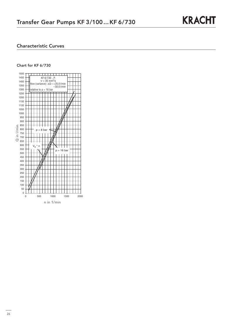
Chart for KF 6/730
KF 6/730 ..P.ν = 35 mm2/s
flow (variance): ΔQ = + 25.0 l/min-- 50.0 l/min
relative to p = 16 bar
n in 1/min
Q in
l/m
in
0 500 1000 1500 2000
1500
1450
1400
1350
1300
1250
1200
1150
1100
1050
1000
950
900
850
800
750
700
650
600
550
500
450
400
350
300
250
200
150
100
50
0
Vg * n
p = 8 bar
p = 16 bar

Note
27
Transfer Gear Pumps KF 3/100...KF 6/730
KF3/100...KF6/730/GB/05.11
Transfer PumpsTransfer pumps for lubricating oil supply equipment, low pressure filling and feed systems, dosing and mixing systems.
Mobile HydraulicsSingle and multistage high pressure gear pumps, hydraulic motors and valves for construction machinery, vehicle-mounted machines.
Flow MeasurementGear and turbine flow meters and electronics for volume and flow metering technology in hydraulics, processing and laquering technology.
Industrial Hydraulics /Test Bench ConstructionCetop directional control and proportional valves, hydraulic cylinders, pressure, quantity and stop valves for pipe and slab construction, hydraulic accessories for industrial hydraulics (mobile and stationary use).
Technology Test benches / Fluid Test benches.
Product Portfolio