Transair , advanced air pipework systems 40 6604 63 40 91,0 161,0 245,0 61,0 116,0 2,050 kg 6604 5...
32
Transair ® , advanced air pipework systems Product catalogue
-
Upload
truongnguyet -
Category
Documents
-
view
224 -
download
2
Transcript of Transair , advanced air pipework systems 40 6604 63 40 91,0 161,0 245,0 61,0 116,0 2,050 kg 6604 5...

Transair®, advanced air pipework systemsProduct catalogue
legrisanglais2 9/07/02 11:42 Page 1

2
Transair®, advanced air pipework systems
Transair® technologyThe quick and easy assembly of Transair® is provided by its innovative technology :quick assembly connection to aluminium pipe (patented system).
Technical specifications Suitable fluids :
• Compressed air(dry, wet, lubricated)
• Vacuum • Inert gas :
argon, nitrogen (other fluids,please consult us)
Max working pressure :• 16 bar - please consult us
for temperature range• 13 bar from -20°C to +60°C
Vacuum level :• 98,7% (13 mbar
absolute pressure)Working temperature :
• From -20°C to +60°C
Excellent resistance to :• Compressor oils
(mineral or synthetic)• Ultra-violet rays
(For other fluids please consult us)
Storage temperature :• From -40°C to +80°C
Certification
Our manufacturing process includes individualcontrol and unit dating for all Transair® fittingsand pipe, in order to guaranteetheir quality and traceability.Regarding security, Transair® conforms toEuropean standard 97/23 CEE - § 3.3 (equipment under pressure).
Identification
Transair® is an innovative aluminium pipework system for the distribution of air, easy toassemble thanks to its rapid connection technology. With a wide product range and manyaccessories, Transair® helps you with your air network projects by offering a modern andenergy efficient solution.
Double clamp ring
Mount the nut and double clamp ring onto the pipe ; then tighten
1/2 turn with a spanner
and the connectionis secured
• Quick connection with double clamp ringØ 63 mm
Gripping ring Insert the pipe into the component The connection is made
• Quick connection with gripping ringØ 16,5 mm - 25 mm - 40 mm
Part numbers have been chosen by a method ofmnemonics. Each Transair® component is identified by :
• Its series• Pipe OD• Thread code or second pipe OD
Series
Ø Pipe OD
Thread code6661 40 21
Transair®
meets the requirements of
ASME B31.1
Transair® components are non-flammable, with no propagation of flame.Materials 100 % recyclable. For silicone free applications : please contact us.
legrisanglais2 9/07/02 11:42 Page 2

T r a n s a i r®
3
4-5
6
7
8
9
10-11
11
12-13
14-15
16-19
20-22
23
24-26
27
28
29
30
31
Contents
Legris has a policy of continual product development and, therefore, reserves the right to modify any productsshown in this catalogue, without notification. All dimensions are indicative.
Pipe-to-pipe and stud connectors
Rigid aluminium pipe & Flexible hose
Quick assembly brackets
Ball valves
Wall brackets
Tools
Pressurised system outlets
Fixture accessories
Air distribution columns
Composite automatic safety couplers
Metal automatic safety couplers
Hose reels & Blowgun
Connection accessories
Tubes & Hoses
FRLs, Automatic drain & Accessories
Installation guide
Index
Transair® worldwide
ABC
legrisanglais2 9/07/02 11:43 Page 3

Pipe-to-pipe and stud connectors
Male stud fitting, BSP taper
ØD C Transair® E G H16,5 R1/4 6605 17 13 9,5 34,0 62,5 0,101
16,5 R1/2 6605 17 21 15,0 34,0 68,0 0,111
25 R1/2 6605 25 21 15,0 44,5 70,5 0,165
25 R3/4 6605 25 27 15,0 44,5 71,5 0,178
25 R1” 6605 25 34 16,0 44,5 71,5 0,230
40 R1” 6605 40 34 16,0 67,0 111,5 0,585
40 R1”1/4 6605 40 42 21,5 67,0 111,5 0,540
40 R1”1/2 6605 40 49 24,5 67,0 114,5 0,625
63 R2” 6605 63 48 20,0 91,0 118,5 1,090
63 R2”1/2 6605 63 47 25,0 91,0 130,5 1,480
kg
6605 Equal elbow
ØD Transair® G L Z16,5 6602 17 00 34,0 58,0 31,0 0,069
25 6602 25 00 44,5 68,0 40,0 0,129
40 6602 40 00 67,0 107,0 45,0 0,415
63 6602 63 00 91,0 122,0 61,0 0,980
kg
6602
45° elbow
ØD Transair® G L Z25 6612 25 00 44,5 57,0 29,0 0,115
40 6612 40 00 67,0 90,0 45,0 0,370
kg
6612Equal pipe-to-pipe connector
ØD Transair® G L Z16,5 6606 17 00 34,0 120,5 33,5 0,071
25 6606 25 00 44,5 151,5 48,0 0,129
40 6606 40 00 67,0 205,0 57,0 0,400
63 6606 63 00 91,0 171,5 25,0 0,860
kg
6606
4
Materials6605 Ø 16,5 - 25 - 40 Ø 63
• Body Plated-brass Treated brass• Nuts Engineering grade plastic Treated aluminium
6606/6676/6602/6612/6604 Ø 16,5 - 25 - 40 Ø 63• Body Engineering grade plastic Treated aluminium • Nuts Engineering grade plastic Treated aluminium
Equal pipe-to-pipe connector with vent
ØD Transair® G L Z25 6676 25 00 44,5 151,5 48,0 0,150
40 6676 40 00 67,0 205,0 57,0 0,420
63 6676 63 00 91,0 171,5 49,0 0,855
kg
6676 Equal tee
ØD Transair® G H L Z1 Z216,5 6604 17 00 34,0 58,0 120,5 33,5 31,0 0,100
25 6604 25 00 44,5 67,5 151,5 48,0 40,0 0,190
40 6604 40 00 67,0 102,5 205,0 57,0 57,0 0,595
63 6604 63 00 91,0 122,0 245,0 61,0 61,0 1,410
kg
6604
Model supplied with 1/4" fitting and Ø8 mm plug-in cap
• Quick connection• Full bore design• Interchangeable and reusable• Non-flammable materials
(UL94-HB standard) The range of Transair® pipe-to-pipe and stud connectors provides versatility of design and helps to overcome constraints often encountered
with the structure of industrial buildings
• Max working pressure :- 16 bar – please consult us for temperature range- 13 bar from -20°C to +60°C
• Vacuum level : 98,7% (13mbar absolute pressure)• Working temperature : -20°C to +60°C
legrisanglais2 9/07/02 11:43 Page 4

T r a n s a i r®
Equal cross
L2
L1
Z1
Z2
ØG
ØD Transair® G L1 L2 Z1 Z225 6607 25 00 44,5 152,0 135,0 48,0 40,0 0,240
kg
6607
Reducing tee
ØG
L
Z1
ØD2
ØD1Z2
H
ØD1 ØD2 Transair® G H L Z1 Z263 40 6604 63 40 91,0 161,0 245,0 61,0 116,0 2,050
kg
6604
5
Materials6604/6607/6625 Ø 16,5 - 25 - 40 Ø 63
• Bodies Engineering grade plastic Treated aluminium• Nuts Engineering grade plastic Treated aluminium
6621 :Treated aluminium
6666/6651 Ø 16,5 - 25 - 40 Ø 63• Bodies Plated brass Treated aluminium• Nuts Engineering grade plastic Treated aluminium
Male adaptor, BSP taper
ØD
C
L
H
Ø 6
3
Ø 40
61
116
2580
Ø 63
Ø 40
ØD C Transair® L H16,5 R1/2 6621 17 21 42,2 5,0 0,020
25 R1/2 6621 25 21 49,0 7,0 0,035
25 R3/4 6621 25 27 49,0 7,0 0,057
40 R1”1/4 6621 40 42 73,7 8,0 0,139
40 R1”1/2 6621 40 49 75,7 10,0 0,172
kg
6621
Manifold
L1
Ø12
L2 N N N
ØG
ØD
L
Z Z
ØD Transair® G L L1 L2 N Z25 6651 25 12 04 44,5 271,0 151,0 23,0 35,0 108,0 1,060
40 6651 40 12 04 67,0 400,0 204,0 27,0 50,0 152,0 2,800
kg
6651
Vented end-cap
ØG
E
ØD
L
H
ØD Transair® E G H L16,5 6625 17 00 25,5 34,0 45,5 62,5 0,145
25 6625 25 00 33,0 44,5 47,0 75,0 0,164
40 6625 40 00 34,5 67,0 55,0 98,5 0,189
63 6625 63 00 31,0 91,0 74,0 105,0 0,480
kg
6625
Plug-in reducer
ØG ØD2ØD1
Z
L
ØD1 ØD2 Transair® G Z L25 16,5 6666 17 25 34,0 50,0 77,0 0,050
40 25 6666 25 40 44,5 71,5 99,0 0,116
kg
6666
Screw-on reducer
L
ØGØD2
ØD1 ØD2 Transair® G L63 40 6666 40 63 67,0 112,5 0,940
kg
6666
Supplied with 4 Ø12 mm plugs (3126 12 00)
The 63 mm to 40 mm reducer is secured by a 63 mm screw-on nut.
Model Ø16,5 mm : supplied with Ø6 mm plug Models Ø25, Ø40 and Ø63 mm : supplied with Ø8 mm plug.
legrisanglais2 9/07/02 11:43 Page 5

Rigid aluminium calibrated pipe • Clean air • Optimum flow rate performance• Low weight• Suitable fluids : compressed air, vacuum, nitrogen, argon
(other fluids, please consult us)• Max working pressure :
- 16 bar – please consult us for temperature range- 13 bar from -20°C to +60°C
• Vacuum : 98,7% (13 mbar absolute pressure)• Working temperature : -20°C to +60°C• Extruded pipe (conforms to EN 755.2, EN 755.8
and EN 573.3 standards)
Flexible hose• Compressor outlets (absorption of vibration)• To bypass obstacles and join different levels• Expansion loops• Max working pressure :
- 16 bar – please consult us for temperature range- 13 bar from -20°C to +60°C
• Vacuum : 98,7% (13 mbar absolute pressure)• Working temperature : -20°C to +70°C• Resistant to mineral and synthetic compressor oils• Fire resistant (conforms to ISO 8030 standard for compressed
air flexible hose and EN 12115 for vacuum flexible hose)
Rigid aluminium pipe & Flexible hose
3m rigid aluminium pipe
Øext. Øint. Transair® L (m)
16,5 13 1003A17 04 00 2,930 0,750
25 22 1003A25 04 00 2,903 1,100
40 37 1003A40 04 00 2,885 1,900
63 59 1003A63 04 00 2,950 3,200
kg
1003A
6 m rigid aluminium pipe
Øext. Øint. Transair® L (m)
25 22 1006A25 04 00 5,903 2,200
40 37 1006A40 04 00 5,885 4,000
63 59 1006A63 04 00 5,950 6,400
kg
1006A
Flexible hose for compressed air networks
Min For use withØext. Øint. Transair® L bend Transair®
radius (mm) pipe diameterkg
1001E
6
Materials
38 25 1001E25 00 01 0,570 75 25 0,544
38 25 1001E25 00 03 1,500 75 25 1,488
38 25 1001E25 00 04 2,000 75 25 1,997
54 40 1001E40 00 02 1,150 160 40 2,075
54 40 1001E40 00 04 2,000 160 40 3,319
54 40 1001E40 00 05 3,000 160 40 4,000
79,5 63 1001E63 00 08 1,400 300 63 3,920
79 63 1001E63 00 05 3,000 250 63 8,060
79 63 1001E63 00 06 4,000 250 63 10,700
Flexible hose for vacuum networks
Anti whip-lash strap (1)
Min For use withØext. Øint. Transair® L bend Transair®
radius (mm) pipe diameterkg
1001E
36 25 1001E25V00 01 0,570 75 25 0,900
36 25 1001E25V00 03 1,500 75 25 2,500
36 25 1001E25V00 04 2,000 75 25 3,000
52 40 1001E40V00 07 0,950 160 40 1,750
52 40 1001E40V00 04 2,000 160 40 4,000
52 40 1001E40V00 05 3,000 160 40 4,500
79,5 63 1001E63 00 08 1,400 300 63 3,920
76 63 1001E63V00 05 3,000 250 63 8,740
76 63 1001E63V00 06 4,000 250 63 10,890
Sticker for vacuum networks
Transair®
0000 01 68
(1) Prevents whip-lash should Transair® flexible hose become disconnected whilst under pressure.Conforms to the ISO 4414 safety standard.
0000
• Rigid aluminium pipe :- Paint Qualicoat certified
• Anti whip-lash strap- steel
• Flexible hose for air compressed networks :- Hose and coating : black SBR- Reinforcement : synthetic braiding
• Flexible hose for vacuum networks :- Hose and coating : black SBR/NBR- Reinforcement : spiral steel wire
6 m
3 m
L
L
6698
Anti whip-lash strap (1)
6698
6698 99 03
6698 99 03
legrisanglais2 9/07/02 11:43 Page 6

• Quick assembly without cutting the pipe
• Horizontal or vertical connection
• Integral condensate retention device
• Non-flammable (conforms to UL94-HB standard)
In order to add a new outlet without shutting off the air supply, please use the "Pressurised System Connection Tool" (page 11).
Reduced overall dimension.Protection of downstream network.
• Max working pressure :- 16 bar – please consult us for temperature range- 13 bar from -20°C to +60°C
• Vacuum : 98,7% (13 mbar absolute pressure)
• Working temperature : -20°C to +60°C
Quick assembly bracketsT r a n s a i r®
Quick assembly bracket
ØG
ØD
E
H
L N
ØD
Z
ØD Transair® E G H L N Z25 6662 25 00 31,0 44,5 79,5 36,0 47,5 52,0 0,115
40 6662 40 00 37,0 67,0 119,5 72,0 74,5 74,0 0,365
kg
6662
Mini-bracket with coupler
ØD C Transair® Profile Bore (mm)25 G1/2 6660 25 U1 ISO B 5,5
25 G1/2 6660 25 U2 ISO B 8
25 G1/2 6660 25 E4 EURO 7,2
25 G1/2 6660 25 A1 ARO 5,5
40 G1/2 6660 40 U1 ISO B 5,5
40 G1/2 6660 40 U2 ISO B 8
40 G1/2 6660 40 E4 EURO 7,2
40 G1/2 6660 40 A1 ARO 5,5
63 G1/2 6660 63 U1 ISO B 5,5
63 G1/2 6660 63 U2 ISO B 8
63 G1/2 6660 63 E4 EURO 7,2
63 G1/2 6660 63 A1 ARO 5,5
6660Quick assembly reducing bracket
ØD1
E
HZ
L N
ØG
ØD2
ØD1 ØD2 Transair® E G H L N Z25 16,5 6662 25 17 30,8 34,0 84,0 36,0 47,5 57,0 0,099
40 16,5 6662 40 17 39,0 34,0 99,8 37,2 67,5 73,0 0,138
40 25 6662 40 25 39,0 44,5 95,0 37,2 67,5 68,0 0,154
63 25 6662 63 25 63,5 44,5 103,0 50,0 108,5 75,0 0,330
kg
6662
Quick assembly mini-bracket with female thread
Ø D
L N
C
E
HM
ØD C Transair® E H L N M25 G1/2 6661 25 21 30,8 51,3 36,0 46,5 90,1 0,116
40 G1/2 6661 40 21 39,2 66,0 37,2 58,2 113,4 0,156
63 G1/2 6661 63 21 63,5 75,4 50,0 98,5 148,0 0,320
63 G3/4 6661 63 27 63,5 75,4 50,0 98,5 148,0 0,460
kg
6661
7
Materials6662/6661*/6660 Ø 16,5 - 25 - 40 Ø 63
• Body Engineering grade plastic* Engineering grade plastic• Nut Engineering grade plastic Engineering grade plastic
Coupler : composite material(see details p16-19)
*Brass insert
legrisanglais2 9/07/02 11:43 Page 7

• Quick connection• Available in lockable version• Manual or piloted operation• Non-flammable
(conforms to UL94-HB standard) Transair® ball valves placed regularly throughout the network and at key locations, such as compressor outlets and upstream of pneumatic tools, allow ease of system isolation, adaptation and maintenance.
• Working pressure :- 16 bar – please consult us for temperature range- 13 bar from -20°C to +60°C
• Vacuum level : 98,7% (13 mbar absolute pressure)• Working temperature : -20°C to +60°C
Ball valves
Double female
ØG
L
N
ØD
kg
4002 Remote controlshut-off valve
ØG
L
ØD
Ø4 Ø4
ØD Transair® E G40 4230 00 40 67 261 1,805
kg
4230
Lockable valve
ØG
L
N
ØD
4012
Pilot kit
H K
L
K1
4299Double female, vented
ØG
L
Z2Z1
ØD
N
ØD Transair® G L N Z1 Z216,5 4089 17 00 34,0 120,0 69,5 27,0 40,0 0,340
25 4089 25 00 44,5 152,0 108,5 41,0 59,0 1,090
kg
4089
Lockable valve, vented4099
8
Materials4089/4099/4230 Ø 16,5 - 25 - 40• Body Plated brass• Nut Engineering grade plastic
4002/4012 Ø 40 Ø63• Body Engineering grade plastic Engineering grade plastic• Nut Engineering grade plastic Plated aluminium
4934/4981• Body Plated brass• Seal PTFE and nitrile
Min working pressure : 4 bar • Max working pressure. : 13 barThe Transair® remote control shut-off valve is supplied with a plugged vent hole. This allows venting of the downstream network, after closing the valve.
Model 4099 17 00 : supplied with Ø6 mm plug Model 4099 25 00 : supplied with Ø8 mm plug
Mini valve, male and female,BSP taper
CC
M
H
L
F
C Transair® F H L MR1/2 10 4981 10 21TR 25 31 46 20,5 0,137
kg
4981
Ball valve,male and female, BSP taper
FC
L
M
H
H1
L2 L1
C
C Transair® F H H1 L L1 L2 MR3/4 20 4934 20 27TR 31 39 60 16 18,5 110 0,36 0,385
R1" 25 4934 25 34 TR 38 49 64 19 21,5 110 0,57 0,591
R1"1/4 32 4934 32 42TR 48 59 78 21 24 160 0,94 1,069
R1"1/2 40 4934 40 49TR 54 73 86 21 24 160 1,5 1,515
kg
4934
Transair® H K K1 L4299 03 01 145 106 70 82 0,795
This pilot kit comprises : pneumatic ON/OFF switch, maximum 10 bar operating pressure, twin 4mm OD polyurethane tube, length 10m, plastic box.
kg
DN
DN
Max working pressure. : 25 bar
Max Working pressure : 10 bar
ØG
L
ØD
N
ØD Transair® G L N40 4002 40 00 67,0 205,0 122,0 0,600
63 4002 63 00 67,0 278,0 185,0 2,425
kg
ØD Transair® G L N Z1 Z216,5 4099 17 00 34,0 121,0 69,0 27,0 40,0 0,392
25 4099 25 00 44,5 151,7 108,3 41,0 59,0 1,230
kg
Model 4099 17 00 : supplied with Ø6 mm plug Model 4099 25 00 : supplied with Ø8 mm plug
ØD Transair® G L N63 4012 63 00 67 278,0 185,0 2,425
kg
Ø40 Ø63
legrisanglais2 9/07/02 11:44 Page 8

• Working pressure :- 16 bar – please consult us for temperature range- 13 bar from -20°C to +60°C
• Vacuum level : 98 ,7% (13 mbar absolute pressure)• Working temperature : -20°C to +60°C
Wall bracketsT r a n s a i r®
9
Materials 6670/6671/6680/6681/6685/6686 Ø 16,5 - 25• Body Plated brass• Nut Engineering grade plastic
1 port wall bracket,BSP parallel
6680
H
K N
ØG
ØD
C
66.5
19,5
ØD C Transair® G H K N16,5 G1/2 6680 17 21 34 65 70,5 82 0,462
25 G1/2 6680 25 21 44,5 81 70,5 82 0,494
kg
2 port wall bracket,BSP parallel
6681
H
K N
ØG
ØD
C
66.5
19,5
ØD C Transair® G H K N16,5 G1/2 6681 17 21 34 65 74,5 82 0,411
25 G1/2 6681 25 21 44,5 81 74,5 82 0,450
kg
1 port wall bracket,with coupler
6670
ØD Transair® Profile Bore (mm)16,5 6670 17 U1 ISO B 5,5
16,5 6670 17 U2 ISO B 8,0
16,5 6670 17 E4 EURO 7,2
16,5 6670 17 A1 ARO 5,5
25 6670 25 U1 ISO B 5,5
25 6670 25 U2 ISO B 8,0
25 6670 25 E4 EURO 7,2
25 6670 25 A1 ARO 5,5
2 port wall bracket,with coupler
6671
ØD Transair® Profile Bore (mm)16,5 6671 17 U1 ISO B 5,5
16,5 6671 17 U2 ISO B 8,0
16,5 6671 17 E4 EURO 7,2
16,5 6671 17 A1 ARO 5,5
25 6671 25 U1 ISO B 5,5
25 6671 25 U2 ISO B 8,0
25 6671 25 E4 EURO 7,2
25 6671 25 A1 ARO 5,5
1 port threaded wall bracket,BSP parallel
6685
N C1
C2
H
66,5 K
C1 C2 Transair® H K NG1/2 G1/2 6685 21 21 48 72,5 82 0,475
kg C1 C2 Transair® H K NG1/2 G1/2 6686 21 21 48 66,5 82 0,420
kg
2 port threaded wall bracket,BSP parallel
6686
N
66,5
C1
C2
H
K
1/2” BSP parallel connection between the wall bracket and the composite safety coupler. 1/2” BSP parallel connection between the wall bracket and composite safety coupler.Couplers supplied with the wall bracket are ready for immediate use.
Coupler : composite material (see details p16-19)
• 1 port or 2 ports• Pre-assembled composite safety coupler (6670)• Mounting on walls or machinery• Non-flammable (conforms to UL94-HB standard)
legrisanglais2 9/07/02 11:44 Page 9

• Practical tools for the installation and extension of Transair® air pipe networks • Presented in a carrying case, or available as separate parts
Tools
10
Drilling jig for rigid aluminium pipeØ 25 mm and Ø 40 mm
6698
Transair® H L6698 01 01 120 80 0,860
kg
Deburring toolfor rigid aluminium pipe
6698
Transair® L6698 04 02 140 0,020
kg
Cutterfor rigid aluminium pipe
6698
Transair®
6698 03 01 0,760
kg
Drilling jig for rigid aluminium pipeØ 63 mm
6698
H
L
Transair® H L6698 01 02 134 155 2,245
kg
Chamfer toolfor rigid aluminium pipe
6698
Transair® H6698 04 01 64 0,113
kg
Drilling toolfor rigid aluminium pipe
6698
ØD1 ØD2 Transair® H16 12 6698 02 02 25 71 0,147
22 12 6698 02 01 40 - 63 71 0,148
kgFor pipeTransair®
May be used with all types of drills. • Rotation speed : 650 rpm maximum.
For Ø 16.5, 25, 40 and 63 mm.
After drilling, deburr and clean the pipe.
After drilling, deburr and clean the pipe. For Ø 16.5, 25 and 40 mm.
legrisanglais2 9/07/02 11:44 Page 10

We recommend however that the pipework networkis drained prior to assembly of an outlet
Thanks to lateral dismantling of Transair® pipe andthe “easily assembled” outlet brackets (see pages 6 and 7),
this operation can be done very quickly(less than 7 min. for a new outlet)
and guarantees the interior cleanliness of the circuit.
T r a n s a i r®
T r a n s a i r®
11
Set of tightening spanners for 63 mm nuts
Transair®
6698 05 03 0,734
kg
6698
Pressurised system drilling tool
C Ø Transair® L E NG1/2 13 EA98 06 00 330,0 154,0 30,5 0,545
kg
EA98 Pressurised system bracket
ØD Transair®
25 EA98 06 01
40 EA98 06 02
63 EA98 06 03
EA98
Tool case
Transair® H L6698 00 03 315 290 5,900
kg
6698
Pressurised system outlets
This set includes 2 tightening spanners. This tool case simplifies the use and transportation of tools.It contains all the tools necessary for completing a Transair® installation :
- Drilling jigs 6698 01 01 and 6698 01 02- Drilling tools 6698 02 01 and 6698 02 02- Cutter for rigid pipe 6698 03 01- Chamfer tool 6698 04 01- Deburring tool 6698 04 02- Set of tightening spanners 6698 05 03- Marking tool 6698 04 03
• Ideal for fast assembly of new pressurised outlets,without venting the compressed air network.
• The drilling tool can be used with moststandard drills
Marking toolfor aluminium pipe
6698
L1
L2
H
Transair® H L1 L26698 04 03 88 73 33 0,040
kg
Materials Pressurised system drilling tool :• Body - aluminium• Drill - steel• Adaptor and Cap - brass• Silencer - plastic
Ball valve with bracket(1/2” BSP parallel thread)
The marking tool enables connection guidelines to be marked on cut lengths of Transair® pipe. Thesemarks indicate the insertion limits of the pipe into the fitting in order to ensure good airtight connectionand security of grip.
legrisanglais2 9/07/02 11:44 Page 11

• Can be adapted to all pipework configurations • For suspension of pipes, from walls, partitions, beams, cable trays, Canalis electrical installations, etc…,
vertically and horizontally• Perfectly suited for use with Transair® networks
Fixture accessories
12
U-channel clip fixing setØ 63 mm
6699
C Transair® H K LM10 6699 01 03 35 20 50 0,095
kg
U-channel, 2 metres
Transair® H L (m) L16699 01 01 25 2 25 1,500
kg
6699Fixing clip for rigid pipe
ØD C Transair® H1 H K L16,5 M6X1 6697 17 00 46 61 30 32,5 0,027
25 M6X1 6697 25 00 46 65,5 30 38,5 0,030
40 M6X1 6697 40 00 46 74,5 30 50 0,036
63 M10X1,5 6697 63 00 90 127,5 30 73,5 0,050
6697
Clip adaptor for threaded rod
C1 C2 Transair® E F HM6x1 M8x1,25 6697 00 01 16 13 30 0,035
M6x1 M10x1,5 6697 00 02 16 13 30 0,054
6697
U-channel fixing bracket
L
H
Transair® H L6699 01 02 106 40 0,170
kg
6699
Transair® fixing clips are designed to bear a maximum weight of 20 kg. However, to ensure good stability of the network, we recommend the use of at least 2 clips per pipe i.e :
- maximum 1,5 m space between clips for 3 m lengths of pipe.- maximum 3 m space between clips for 6 m lengths of pipe.
Use only this clip for fixing Transair® rigid pipe, all other type of pipe clips are to be avoided.Fix the clip to a rigid support (U-channel, cable tray) to allow for expansion whilst retaining the pipe. For RSJ fixing clips please see 6699 03 02 on Page 13
The use of this adaptor facilitates the suspension of Transair® under M8 or M10 threaded rod.
Materials - Fixing clips : polymer H.R. - Spacer : polymer H.R.- Clip adaptor : brass- U-channel : galvanised steel
- Set of fixing accessories : galvanised steel- Clip fixing set Ø 63 mm : galvanised steel
The set comprises :- 1 channel nut + M10 threaded rod- 1 washer- 1 nut
The set comprises :- 1 bracket- 1 screw- 1 nut- 1 end cap
kg
Spacer
ØD Transair® H H1 K L11 6697 00 03 49,5 44 34 33 0,020
6697
This spacer, in association with the Transair® clip, allows consistent alignment of pipes.
kg
90mm
46mm
44mm
Ø63 Ø40
90 mm46 mm44 mm
legrisanglais2 9/07/02 11:44 Page 12

T r a n s a i r®
13
Push-on type beam clamp
K
H
øT
Transair® H K ØT6699 02 01 44 1,5 to 3 M6 68
6699 02 02 46 3 to 8 M6 68
6699 02 03 54 8 to 14 M6 68
6699 02 04 66 14 to 20 M6 68
6699 02 05 44 1,5 to 3 M10 68
6699 02 06 46 3 to 8 M10 68
Max carryingload (kg)
6699
Fixture on KN CANALIS
K
H
N
K
H
N
Transair® H K N6699 10 01 200 60 37 0,110
kg
6699
Fixture on cable tray
L
10 x 30
M
kg
6699
Fixture on KS CANALIS
Transair® H K N6699 10 02 200 60 30 0,120
kg
6699
U-channel fixture bracket for RSJ
H N
L
N
kg
6699
Screw type beam clamp
K øT1
øT2
øT
Transair® ØT2 ØT ØT1 K6699 03 01 10,7 6,5 10,7 18 45
6699
Max carryingload (kg)
Materials- Fixture on KN and KS Canalis : Bichromated steel zinc-coated- Push-on type beam clamp and screw type beam clamp : galvanised steel- Fixture on cable tray : galvanised steel- Fixture on RSJ : galvanised steel and brass screw
Transair® H L N6699 03 02 49 41 25 0,080
Supplied with one 8 x 25 needle screw
11 mm max Horizontal assembly Vertical assembly
Ø tray rod : 4 to 6 mm
kg
Transair® L M6699 10 03 140 22 0,035
kg
legrisanglais2 9/07/02 11:45 Page 13

• Provide an enclosed energy supply to work stations and production areas
• Can be used vertically or horizontally• Suitable for enclosure of electrical cabling
Protection and rationalisation of drops.
• Fluids : compressed air, vacuum, argon, nitrogen(for other fluids, please consult us)
• Maximum working pressure : 13 bar• Vacuum level : 98,7% (13 mbar absolute pressure)• Working temperature : -20°C to +60°C
Air distribution columns
14
Column with floor/wall fixing
Transair® H P6699 04 01 2500 60 6,000
kg
6699 Column with floor/ceiling fixing
Transair® H H1 (maxi) L6699 04 02 2450 600 100 7,000
kg
6699
Module with one threaded outlet
C F
L1L
ØDH1
H
H2
L2
ØD C Transair® F H H1 H2 L L1 L214 G1/4 6699 04 60 24 62 29,5 8,5 136,5 109,5 20 0,429
14 G1/2 6699 04 60 01 24 75,5 33 18,5 137 103 23 0,470
kg
6699 Module with ball valve
H1
H
H2
M
L1
L
ØD
L2
ØD Transair® H H1 H2 L L1 L2 M14 6699 04 63 82,5 29,5 29 136,5 109,5 20 69,5 0,552
kg
6699
Materials- Column : anodised aluminium- Module : aluminium
H
P
HH1
L
With telescopic cylinder
legrisanglais2 9/07/02 11:45 Page 14

T r a n s a i r®
15
Pilot valve module
H
H2
Ø29
L
Ø4
Transair® H H2 L6699 04 65 82 25 124,5 0,424
kg
6699
Plug
L1
L
ØG
ØD
ØD Transair® G L L114 3126 14 00TR 16 49 23,5 0,005
kg
3126 Female stud fitting, BSP parallel
FH
ØD
C
E
ØD C Transair® E F H14 G3/8 3114 14 17TR 14 22 42,5 0,120
kg
3114
Module with pressure gauge
H1
H
H2
L1L2
L
ØD
Ø40
F
ØD Transair® F H H1 H2 L L1 L214 6699 04 64 24 28 29,5 44,5 136,5 109,5 20 0,510
kg
6699
2
1
3 1
2
In order to meet users requirements, Transair® air distribution columns canbe installed on the work-bench or within the production area.
Installation
ColumnsWall and floor fixing or floor and ceiling fixing
1- Fix the mounting bracketon the wall2- Fix the column3- Screw sub-base to the floor
1- Fix the sub-base to the floor
2- Release the cylinder to lock the column.
1- Measure and cut at the required height
2- Connect the modules together
3- Fix into the column
Modules
To plug the end of a module. To connect modules to braided PVC hose, using hosetail adaptor EF26 – see Page 26.
The pilot valve module includes :- pneumatic ON/OFF switch, maximum operating pressure 10 bar- twin polyurethane tube, 10m length, 4mm OD
PVC hose 1025V(page 27)
Hosetail adaptor EF26(page 26)
Female stud fitting3114 14 17TR
Plug3126 14 00TR
legrisanglais2 9/07/02 11:46 Page 15

• Suitable fluids : compressed air , argon, nitrogen(please consult us for other fluids)
• Working pressure : 16 bar maximum• Working temperature : from -20°C to +60°C
Composite automatic safety couplers – ISO B profile - 5,5 mm
16
Male body, BSP parallelCP01
Female body, BSP parallelCP14
Body with hosetailCP21
Female probe, BSP parallelCA86
Probe with hosetailCA94
Male probe , BSP parallelCA87
Probe adaptorCA90
• For quick and repetitive connection and disconnection • 100% safety - ISO 4414 and EN983 compliant• Very high flow, extremely small pressure loss• Lightweight and robust• Improved hand grip• Fast vent time
Materials • Body : reinforced polymer• Sleeve : reinforced polymer• Spring : stainless steel• Seal : nitrile• Thread : nickel plated brass
• Ball bearings : stainless steel• Probe : nickel plated brass• Probe adaptor : nickel plated brass
with polymer sleeve
C Transair®
G1/4 CP01 U1 02
G3/8 CP01 U1 03
G1/2 CP01 U1 04
C Transair®
G1/4 CP14 U1 02
G3/8 CP14 U1 03
G1/2 CP14 U1 04
C Transair®
G1/4 CA87 U1 02
G3/8 CA87 U1 03
G1/2 CA87 U1 04
ØD Transair®
6 CP21 U1 06
8 CP21 U1 08
10 CP21 U1 10
C Transair®
G1/4 CA86 U1 02
G3/8 CA86 U1 03
G1/2 CA86 U1 04
ØD Transair®
6 CA94 U1 06
8 CA94 U1 08
10 CA94 U1 10
Transair® Profile Profile
CA90 U1 01 ISO C6 to ISO B6
CA90 U1 03 PCL to ISO B6
Flow curve - pressure lossPressure loss in bar. To convert Nm3/h to cfm use a cœfficient of 0.588.
Flow in Nm3/h
Safety ISO 6150 BAFNOR NF 49-053US.MIL.C4109CEJN 310RECTUS 23-24
CA90 U1 01 CA90 U1 03
Flow : 1250 Nl/min (44 cfm)
Complete with sealing ringComplete with sealing ring
Suitable for use with Transair® PVC hose (see p. 27)Suitable for use with Transair® PVC hose (see p. 27)
00
0,2
0,4
0,6
0,8
30 60 90
legrisanglais2 9/07/02 11:46 Page 16

Transair® composite automatic safety couplers complywith worldwide ISO 4414 and European EN983
safety standards. Disconnection is by a double twist of the sleeve – a safety feature that breaks deliberately with
common practice in order to avoid accidental disconnection.
T r a n s a i r®
17
Composite automatic safety couplers – ISO B profile - 8 mm
Male body, BSP parallelCP01
Female body, BSP parallelCP14
Body with hosetailCP21
Female probe, BSP parallelCA86
Probe with hosetailCA94
Male probe, BSP parallelCA87
Materials • Body : reinforced polymer• Sleeve : reinforced polymer• Spring : stainless steel• Seal : nitrile
• Ball bearings : stainless steel• Probe : nickel plated brass, nickel plated steel
C Transair®
G1/4 CP01 U2 02
G3/8 CP01 U2 03
G1/2 CP01 U2 04
C Transair®
G1/4 CP14 U2 02
G3/8 CP14 U2 03
G1/2 CP14 U2 04
C Transair®
G1/4 CA86 U2 02
G3/8 CA86 U2 03
G1/2 CA86 U2 04
ØD Transair®
8 CA94 U2 08
10 CA94 U2 10
13 CA94 U2 13
ØD Transair®
8 CP21 U2 08
10 CP21 U2 10
13 CP21 U2 13
C Transair®
G1/4 CA87 U2 02
G3/8 CA87 U2 03
G1/2 CA87 U2 04
Flow curve – pressure lossPressure loss in bar. To convert Nm3/h to cfm use a cœfficient of 0.588.
Flowin Nm3/h
Safety ISO 6150 BAFNOR NF 49-053US.MIL.C4109CEJN 430RECTUS 30
1st rotation in direction of the arrow : circuit rapidly-
flushed out, probe side.
2nd rotation in direction of the arrow : safe disconnection of body and probe.
21
Flow : 2400 Nl/min (85 cfm)
Complete with sealing ringComplete with sealing ring
Suitable for use with Transair® PVC hose (see p. 27)Suitable for use with Transair® PVC hose (see p. 27)
00
0,2
0,4
0,6
0,8
30 60 90 120 150
legrisanglais2 9/07/02 11:46 Page 17

Composite automatic safety couplers – European profile - 7,2 mm
18
Male body, BSP parallelCP01
Female body, BSP parallelCP14
Body with hosetailCP21
Female probe, BSP parallelCA86
Probe with hosetailCA94
Male probe , BSP parallelCA87
Materials • Body : reinforced polymer• Sleeve : reinforced polymer• Spring : stainless steel• Seal : nitrile
• Ball bearings : stainless steel• Probe : nickel plated brass
• Fast vent time• Suitable fluids : compressed air, argon, nitrogen
(please consult us for other fluids)• Working pressure : 16 bar maximum• Working temperature : from -20°C to +60°C
• For quick and repetitive connection and disconnection • 100% safety - ISO 4414 and EN 983 compliant.• Very high flow, extremely small pressure loss• Lightweight and robust• Improved hand grip
Flow curve - pressure lossPressure loss in bar. To convert Nm3/h to cfm use a cœfficient of 0.588.
Flow in Nm3/h
C Transair®
G1/4 CP01 E4 02
G3/8 CP01 E4 03
G1/2 CP01 E4 04
C Transair®
G1/4 CA87 E4 02
G3/8 CA87 E4 03
G1/2 CA87 E4 04
C Transair®
G1/4 CA86 E4 02
G3/8 CA86 E4 03
G1/2 CA86 E4 04
ØD Transair®
8 CA94 E4 08
10 CA94 E4 10
13 CA94 E4 13
C Transair®
G1/4 CP14 E4 02
G3/8 CP14 E4 03
G1/2 CP14 E4 04
ØD Transair®
8 CP21 E4 08
10 CP21 E4 10
13 CP21 E4 13
SafetyCEJN 320RECTUS 25-26
Flow : 2000 Nl/min (71 cfm)
Complete with sealing ringComplete with sealing ring
Suitable for use with Transair® PVC hose (see p. 27)Suitable for use with Transair® PVC hose (see p. 27)
0 30 60 90 120 1500
0,2
0,4
0,6
0,8
legrisanglais2 9/07/02 11:46 Page 18

Transai r®
19
Composite automatic safety couplers – ARO profile - 5,5 mm
Materials • Body : zamak• Sleeve : reinforced polymer• Spring : stainless steel• Seal : nitrile
• Ball bearings : stainless steel• Probe : nickel plated brass, nickel plated steel
Male body, BSP parallelCP01
Female body, BSP parallelCP14
Body with hosetailCP21
Female probe, BSP parallelCA86
Probe with hosetailCA94
Male probe, BSP parallelCA87
Flow curve – pressure lossPressure loss in bar. To convert Nm3/h to cfm use a cœfficient of 0.588.
C Transair®
G1/4 CP01 A1 02
G3/8 CP01 A1 03
G1/2 CP01 A1 04
C Transair®
G1/4 CA87 A1 02
G3/8 CA87 A1 03
G1/2 CA87 A1 04
C Transair®
G1/4 CA86 A1 02
G3/8 CA86 A1 03
G1/2 CA86 A1 04
ØD Transair®
6 CA94 A1 06
8 CA94 A1 08
10 CA94 A1 10
C Transair®
G1/4 CP14 A1 02
G3/8 CP14 A1 03
G1/2 CP14 A1 04
ØD Transair®
6 CP21 A1 06
8 CP21 A1 08
10 CP21 A1 10
1st rotation in direction of the arrow : circuit rapidly
flushed out, probe side.
2nd rotation in direction ofthe arrow : safe disconnectionof body and probe.
Transair® composite automatic safety couplers complywith worldwide ISO 4414 and European EN983
safety standards. Disconnection is by a double twist of the sleeve – a safety feature that breaks deliberately with
common practice in order to avoid accidental disconnection.
Safety ARO 210CEJN 300ORION 44510PARKER 50RECTUS 14-22
21
Flowin Nm3/h
Flow : 1250 Nl/min (44 cfm)
Complete with sealing ringComplete with sealing ring
Suitable for use with Transair® PVC hose (see p. 27)Suitable for use with Transair® PVC hose (see p. 27)
00
0,2
0,4
0,6
0,8
30 60 90
legrisanglais2 9/07/02 11:46 Page 19

• To avoid accidental separation and whiplash, disconnection takes place in 2 stages
• Suitable fluids : compressed air, vacuum, inert gas (argon, nitrogen) (please consult us for other fluids)
• Working pressure : 16 bar maximum
• Vacuum : 13 mbar - 750 mm Hg (98,7 % of vacuum)
• Working temperature : -20°C to +90°C
Metal automatic safety couplers – ISO 6150B - 6 and 8 mm
20
Male body, BSP taper9D05
Female body, BSP parallel9D14
Body with hosetail9D21
Female thread, BSP parallel9086
Probe with hosetail9085
Male thread, BSP taper9084
Materials• Body : anodized duralumin• Probe : nickel-plated steel• Spring : stainless steel• Seal : nitrile
bar0 1 2 3 4 5 6
5,5
20
40
60
80m3/h
bar
8
20
40
60
80
100
100
120
140
160m3/h
0 1 2 3 4 5 6
C Transair®
R1/4 5,5 9D05 09 13P4
R3/8 5,5 9D05 09 17P4
R1/2 5,5 9D05 09 21P4
R1/4 8 9D05 10 13P4
R3/8 8 9D05 10 17P4
R1/2 8 9D05 10 21P4
DN
C Transair®
G1/4 5,5 9D14 09 13P4
G3/8 5,5 9D14 09 17P4
G1/2 5,5 9D14 09 21P4
G1/4 8 9D14 10 13P4
G3/8 8 9D14 10 17P4
G1/2 8 9D14 10 21P4
DN
ØD Transair®
6 5,5 9D21 09 06P4
8 5,5 9D21 09 08P4
10 5,5 9D21 09 10P4
8 8 9D21 10 08P4
10 8 9D21 10 10P4
DN
C Transair®
R1/4 5,5 9084 23 13TR
R3/8 5,5 9084 23 17TR
R1/4 8 9084 30 13TR
R3/8 8 9084 30 17TR
R1/2 8 9084 30 21TR
DN
C Transair®
G1/4 5,5 9086 23 13TR
G3/8 5,5 9086 23 17TR
G1/4 8 9086 30 13TR
G3/8 8 9086 30 17TR
G1/2 8 9086 30 21TR
DN
ØD Transair®
6 5,5 9085 23 06TR
8 5,5 9085 23 08TR
10 5,5 9085 23 10TR
8 8 9085 30 08TR
10 8 9085 30 10TR
13 8 9085 30 13TR
DN
Safety ISO 6150 BUS.MIL.C4109CEJN 310-430RECTUS 23-24-30
Flow :6mm 1333 Nl/min (47 cfm)8mm 2333 Nl/min (82 cfm)
Suitable for use with Transair® PVC hose (see p. 27)Suitable for use with Transair® PVC hose (see p. 27)
To convert Nm3/h to cfm use a cœfficient of 0.588.
legrisanglais2 9/07/02 11:46 Page 20

barbarbar
5,5
20
40
60
80
100m3/h
0 1 2 3 4 5 76 8
8
50
100
150
200m3/h
0 1 2 3 4 5 6 7 8
11
100
200
300
400m3/h
0 1 2 3 4 5 6 7 8
• To avoid accidental separation and whiplash,disconnection takes place in 2 stages
• Suitable fluids : compressed air, inert gas (argon, nitrogen)(please consult us for other fluids)
• Working temperature : -20°C to +60°C
• Working pressure : passage 5,5 mm : from 0 to 12 bar
passage 8 mm : from 0 to 10 bar
passage 11 mm : from 0 to 8 bar
Transai r®
Metal automatic safety couplers - ISO 6150C - 6, 8 and 11 mm
Male body, BSP parallel9D01
Female body, BSP parallel9D14
Body with hosetail9D21
Female thread, BSP parallel9A86
Probe with hosetail9A94
Male thread, BSP parallel9A87
Materials• Body : anodized duralumin• Probe : nickel-plated steel• Spring : stainless steel• Seal : nitrile
C Transair®
G1/4 5,5 9D01 01 13P483G3/8 5,5 9D01 01 17P483G1/2 5,5 9D01 01 21P483G1/4 8 9D01 02 13P483G3/8 8 9D01 02 17P483G1/2 8 9D01 02 21P483
DN
C Transair®
G1/4 5,5 9D14 01 13P483G3/8 5,5 9D14 01 17P483G1/2 5,5 9D14 01 21P483G1/4 8 9D14 02 13P483G3/8 8 9D14 02 17P483G1/2 8 9D14 02 21P483G3/8 11 9D14 03 17P483G1/2 11 9D14 03 21P483
DN
ØD Transair®
6 5,5 9D21 01 06P4838 5,5 9D21 01 08P4839 5,5 9D21 01 09P483
13 5,5 9D21 01 13P48310 8 9D21 02 10P48313 8 9D21 02 13P48313 11 9D21 03 13P48316 11 9D21 03 16P483
DN
C Transair®
G1/8 5,5 9A87 01 10X099G1/4 5,5 9A87 01 13X099G3/8 5,5 9A87 01 17X099G1/4 8 9A87 02 13X099G3/8 8 9A87 02 17X099G1/2 8 9A87 02 21X099G3/8 11 9A87 03 17X099G1/2 11 9A87 03 21X099
DN
C Transair®
G1/8 5,5 9A86 01 10X099G1/4 5,5 9A86 01 13X099
M14x1,25 5,5 9A86 01 70X099G1/4 8 9A86 02 13X099G3/8 8 9A86 02 17X099G1/2 8 9A86 02 21X099G3/8 11 9A86 03 17X099G1/2 11 9A86 03 21X099
DN
ØD Transair®
6 5,5 9A94 01 06X0998 5,5 9A94 01 08X099
10 5,5 9A94 01 10X09913 5,5 9A94 01 13X0996 8 9A94 02 06X0998 8 9A94 02 08X099
10 8 9A94 02 10X09913 8 9A94 02 13X0998 11 9A94 03 08X099
13 11 9A86 03 13X09916 11 9A86 03 16X099
DN
21
Safety ISO 6150 CNF E49-053CEJN 29-381RECTUS 18-84
Flow :6mm 1274 Nl/min (45 cfm)8mm 2633 Nl/min (93 cfm)11mm 5012 Nl/min (177 cfm)
Complete with sealing ring Complete with sealing ring
Suitable for use with Transair® PVC hose (see p. 27)
Suitable for use with Transair® PVC hose (see p. 27)
To convert Nm3/h to cfm use a cœfficient of 0.588.
legrisanglais2 9/07/02 11:46 Page 21

• Single shut-off : when disconnecting the body and the probe cannot be separated as long as the button is depressed, allowing downstream pressure to be manually vented.
• Suitable fluid : compressed air
• Working pressure : from 0 to 10 bar• Working temperature : -20°C to +60°C
Metal automatic safety couplers - ISO 6150C - 6 mm
22
Male body, BSP parallel9D01 Male threaded, BSP parallel9A87
Female thread, BSP parallel9A86
Probe with hosetail9A94
Female body, BSP parallel9D14
Body with hosetail9D21
Materials
• Body : anodized duralumin• Probe : nickel-plated steel• Spring : stainless steel• Seal : nitrile
5,5
20
40
60
80
100m3/h
bar0 1 2 3 4 5 76 8
C Transair®
G1/4 5,5 9D01 01 13P183
G3/8 5,5 9D01 01 17P183
G1/2 5,5 9D01 01 21P183
DN
ØD Transair®
10 5,5 9D21 01 10P183
DN
C Transair®
G1/8 5,5 9A86 01 10X099G1/4 5,5 9A86 01 13X099
M14x1,25 5,5 9A86 01 70X099G1/4 8 9A86 02 13X099G3/8 8 9A86 02 17X099G1/2 8 9A86 02 21X099G3/8 11 9A86 03 17X099G1/2 11 9A86 03 21X099
DN
ØD Transair®
6 5,5 9A94 01 06X0998 5,5 9A94 01 08X099
10 5,5 9A94 01 10X09913 5,5 9A94 01 13X0996 8 9A94 02 06X0998 8 9A94 02 08X099
10 8 9A94 02 10X09913 8 9A94 02 13X0998 11 9A94 03 08X099
13 11 9A86 03 13X09916 11 9A86 03 16X099
DN
C Transair®
G1/8 5,5 9D14 01 10P183
G1/4 5,5 9D14 01 13P183
G3/8 5,5 9D14 01 17P183
DN
C Transair®
G1/8 5,5 9A87 01 10X099
G1/4 5,5 9A87 01 13X099
G3/8 5,5 9A87 01 17X099
G1/4 8 9A87 02 13X099
G3/8 8 9A87 02 17X099
G1/2 8 9A87 02 21X099
G3/8 11 9A87 03 17X099
G1/2 11 9A87 03 21P183
DN
Single shut-off Flow 6mm 1160 Nl/min (41 cfm)ISO 6150 CNF E49-053CEJN 291RECTUS 18
Complete with sealing ring Complete with sealing ring
To convert Nm3/h to cfm use a cœfficient of 0.588.
Suitable for use with Transair® PVC hose (see p. 27)
Suitable for use with Transair® PVC hose (see p. 27)
legrisanglais2 9/07/02 11:46 Page 22
BlowgunEA59
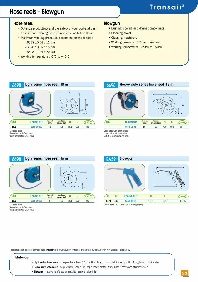
Flow 6 bar : 430 Nl/min. (26.6 m3/h) (15cfm)
C Transair® H LG1/4 3,5 EA59 00 13 125,5 223,0 0,075
kg
Hose reels• Optimize productivity and the safety of your workstations• Prevent hose damage occurring on the workshop floor• Maximum working pressure, dependant on the model :
- 6698 10 01 : 12 bar- 6698 10 02 : 15 bar- 6698 11 01 : 20 bar
• Working temperature : -5°C to +40°C
Blowgun• Dusting, cooling and drying components• Cleaning swarf• Cleaning machinery• Working pressure : 12 bar maximum• Working temperature : -20°C to +50°C
T r a n s a i r®
23
Hose reels - Blowgun
Light series hose reel, 10 m
ØD Transair® H L10,5 6698 10 01 7,5 12 251 300 3,8
kg
6698 Heavy duty series hose reel, 18 m
ØD Transair® H L6698 11 01 10 20 430 600 15,4
kg
6698
Light series hose reel, 16 m
ØD Transair® H L10,5 6698 10 02 8 15 251 390 9,0
kg
6698
Enclosed caseHose clutch with free returnOutlet connection G1/4 male
Enclosed caseHose clutch with free returnOutlet connection G3/8 male
Hose reels can be easily connected to a Transair® air pipework system by the use of a threaded Quick Assembly Mini Bracket – see page 7.
Open case with roller guidesHose clutch with free returnOutlet connection G1/2 male
Materials• Light series hose reels : - polyurethane hose 10m or 16 m long ; case : high impact plastic ; fixing base : black metal
• Heavy duty hose reel : - polyurethane hose 18m long ; case : metal ; fixing base : brass and stainless steel
• Blowgun : - body : reinforced composite ; nozzle : aluminium
Hose i.d.(mm)
Max hosepressure (bar)
Hose i.d.(mm)
Max hosepressure (bar)
Hose i.d.(mm)
Max hosepressure (bar) DN
legrisanglais2 9/07/02 11:46 Page 23

• Offering many possible configurations in BSP parallel and taper • For connection to ancillary equipment on wall brackets or
assembly brackets • For compressor outlets, dryers or receivers
• Suitable fluids : compressed air (dry, wet and lubricated), inert gas (argon, nitrogen), industrial vacuum(other fluids, please consult us)
• Working pressure : 16 bar maximum• Vacuum capability : 13 mbar (98,7%)• Working temperature : -10°C to +80°C
Connection accessories
24
L
C 1 F C 2
C1 C2 Transair® F LR1/4 R1/4 EF00 00 02 14 27
R1/4 R3/8 EF00 02 03 17 27,5
R3/8 R3/8 EF00 00 03 17 28
R1/4 R1/2 EF00 02 04 22 30,5
R3/8 R1/2 EF00 03 04 22 31
R1/2 R1/2 EF00 00 04 22 33,5
R1/2 R3/4 EF00 04 06 27 37,5
R3/4 R3/4 EF00 00 06 27 40
R3/4 R1’’ EF00 06 08 34 43
R1’’ R1’’ EF00 00 08 34 45,5
R1’’ R1’’1/4 EF00 08 10 42 40,5
R1’’1/4 R1’’1/4 EF00 00 10 42 43
R1’’1/4 R1’’1/2 EF00 10 12 48 44
R1’’1/4 R2’’ EF00 10 16 60 49
R1’’1/2 R1’’1/2 EF00 00 12 48 44
R1’’1/2 R2’’ EF00 12 16 60 49
R1’’1/2 R2’’1/2 EF00 12 20 75 52,5
R2’’ R2’’ EF00 00 16 60 52
R2’’ R2‘’1/2 EF00 16 20 75 54,5
R2’’1/2 R2’’1/2 EF00 00 20 75 58
Straight male,BSPT equal/unequal adaptor
EF00
L
E 2
E1
C1 F
C 2
C1 C2 Transair® E1 E2 F LR1/8 G1/4 EF06 01 02 6 11,5 17 14
R1/8 G3/8 EF06 01 03 6 11,5 22 14,5
R1/4 G1/4 EF06 00 02 8 11,5 17 14
R1/4 G3/8 EF06 02 03 8 11,5 22 14,5
R1/4 G1/2 EF06 02 04 8 15 27 18
R3/8 G3/8 EF06 00 03 9 11,5 22 14,5
R3/8 G1/2 EF06 03 04 9 15 27 18
R1/2 G1/2 EF06 00 04 10 15 27 18
R1/2 G3/4 EF06 04 06 11,5 10,5 29 24
R1/2 G1’’ EF06 04 08 11,5 12 36 26,5
R3/4 G3/4 EF06 00 06 13 10,5 29 25,5
R3/4 G1’’ EF06 06 08 13 12,5 36 28
R1’’ G1’’ EF06 00 08 15 12,5 36 30
R1’’ G1’’1/4 EF06 08 10 15 14 45 32
R1’’1/4 G1’’1/4 EF06 00 10 17,5 14 45 34,5
R1’’1/4 G1’’1/2 EF06 10 12 17,5 15 52 35,5
R1’’1/4 G2’’ EF06 10 16 17,5 16 64 36,5
R1’’1/2 G1’’1/2 EF06 00 12 17,5 15 52 35,5
R1’’1/2 G2’’ EF06 12 16 17,5 16 64 36,5
G1’’1/2 G2’’1/2 EF06 12 20 17,5 19 80 39,5
G2’’ G2’’ EF06 00 16 20,5 16 64 39,5
G2’’ G2’’1/2 EF06 16 20 20,5 19 80 42,5
G2’’1/2 G2’’1/2 EF06 00 20 23 19 80 45
Increaser male BSPT to female BSPP
EF06
C 1
L
C 2
F
C1 C2 Transair® F LG1/8 G1/4 EF02 01 02 17 19,5
G1/4 G1/4 EF02 00 02 17 22
G1/8 G3/8 EF02 01 03 22 20
G1/4 G3/8 EF02 02 03 22 23
G3/8 G3/8 EF02 00 03 22 24
G1/4 G1/2 EF02 02 04 27 27
G3/8 G1/2 EF02 03 04 27 27,5
G1/2 G1/2 EF02 00 04 27 30
G1/2 G3/4 EF02 04 06 30 30
G3/4 G3/4 EF02 00 06 30 32
Straight female, BSPP equal/unequal adaptor
EF02
L
C 1 F
C 2
C1 C2 Transair® F LR1/4 G1/8 EF04 01 02 14 16
R3/8 G1/8 EF04 01 03 17 16,5
R3/8 G1/4 EF04 02 03 17 16,5
R1/2 G1/4 EF04 02 04 22 19,5
R1/2 G3/8 EF04 03 04 22 19,5
R3/4 G3/8 EF04 03 06 27 23,5
R3/4 G1/2 EF04 04 06 27 23,5
Reducer male BSPT to female BSPP
EF04
Materials
• nickel-plated brass
100 % recyclable
legrisanglais2 9/07/02 11:46 Page 24

T r a n s a i r®
25
LJ
ø G
C
E
C Transair® E G J LG1/4 EF12 00 02 11 17 13 25,5
G3/8 EF12 00 03 11,5 21 17 28
G1/2 EF12 00 04 14 26 21 33,5
G3/4 EF12 00 06 15 31 27 36,5
Equal female elbow BSPP
EF12
L
J H EØ G
C 2
C 1
2L2
Male stud branch tee, female BSPP, male BSPT
EF16
L
Ø G
J
C 1
C 2
H E
C1 C2 Transair® E G H J LR1/4 G1/4 EF13 00 02 11 17 23,5 13 25,5
R3/8 G3/8 EF13 00 03 11,5 21 26 17 28
R1/2 G1/2 EF13 00 04 14 26 31 21 33,5
R3/4 G3/4 EF13 00 06 15 31 35 27 36,5
Equal female stud elbow BSPP, male BSPT
EF13
LJ
C
H
C Transair® H J LR1/4 EF14 00 02 23,5 13 23,5
R3/8 EF14 00 03 26 17 26
R1/2 EF14 00 04 31 21 31
R3/4 EF14 00 06 35 27 35
Equal male studelbow BSPT
EF14
L2
J
ø G
H E
C
L2
C Transair® E G H J L/2G1/4 EF15 00 02 11 17 25,5 13 25,5
G3/8 EF15 00 03 11,5 21 28 17 28
G1/2 EF15 00 04 14 26 33,5 21 33,5
G3/4 EF15 00 06 15 31 36,5 27 36,5
Equal femaletee BSPP
EF15
Materials
• nickel-plated brass
100 % recyclable
C1 C2 Transair® E G H J L/2R1/4 G1/4 EF16 00 02 17 17 23,5 13 25,5
R3/8 G3/8 EF16 00 03 11,5 21 26 17 28
R1/2 G1/2 EF16 00 04 14 26 31 21 33,5
R3/4 G3/4 EF16 00 06 15 31 35 27 36,5
legrisanglais2 9/07/02 11:46 Page 25

Connection accessories
26
Equal Y, female BSPP,male BSPT
EF11
C1 C2 Transair® E F HR1/2 G1/2 EF11 00 04 14 25 19
Equal Y, female BSPP
C Transair® E F HG1/4 EF10 00 02 11 17 14
G3/8 EF10 00 03 11,5 20 16
G1/2 EF10 00 04 14 25 19
EF10
Materials
• nickel plated brass
100% recyclable
C1 C2 Transair® E G H J L/2R1/4 G1/4 EF17 00 02 11 17 23,5 13 25,5
R3/8 G3/8 EF17 00 03 11,5 21 26 17 28
R1/2 G1/2 EF17 00 04 14 26 31 21 33,5
R3/4 G3/4 EF17 00 06 15 31 36,5 27 36,5
Male stud run tee,female BSPP, male BSPT
EF17
ØD C Transair® E F L6 G1/8 EF26 06 01 6 12 20
6 G1/4 EF26 06 02 8 17 21
8 G1/4 EF26 08 02 8 17 21
8 G3/8 EF26 08 03 9 19 21
10 G1/4 EF26 10 02 8 14 20
10 G3/8 EF26 10 03 9 19 20
10 G1/2 EF26 10 04 10 22 20
13 G1/4 EF26 13 02 8 17 21
13 G3/8 EF26 13 03 9 19 22
13 G1/2 EF26 13 04 10 24 25
16 G3/8 EF26 16 03 9 19 21
16 G1/2 EF26 16 04 10 24 25
Tailpiece adaptor for PVC hose,male BSPP
EF26
Supplied with captive sealing washer. Ideally suited to Transair® PVC hose (see p. 27).
legrisanglais2 9/07/02 11:47 Page 26

T r a n s a i r®
27
Braided PVC hose• Resistant and well adapted to the supply
of machinery and hose reels, etc….• Suitable fluid : compressed air• Working pressure at 23°C : 20 bar • Working temperature : -15°C to +60°C
Polyurethane recoil tubing• Extremely compact, due to small diameter of spirals, Transair® polyurethane
recoil tubing is perfectly suited to installations requiring flexibility in a reduced space. Its straightened extremities and its good resistance to shocks and abrasion enable the user safe and easy manipulation of machinery.
• Suitable fluid : compressed air• Maximum working pressure at 20°C : 10 bar
Tubes and Hoses
Polyurethane recoil tubing, 2m, 4m, 6m extended length
Transair®o.d.tube(mm)
i.d.tube(mm)
BSPTthread
Length oflong straight
section(mm)
Length ofshort straight
section(mm)
Øof thespiralin mm
2 m long
Transair®
4 m long
Transair®
6 m long
Length of spiralin mm
Length of spiralin mm
Length of spiralin mm
6 4 1/4 300 100 32 1470U06 04 13TR 630 1471U06 04 13TR 850 - -
8 5 1/4 500 100 42 1470U08 04 13TR 780 1471U08 04 13TR 1000 1472U08 04 13TR 1230
10 7 1/4 500 100 62 1470U10 04 13TR 780 1471U10 04 13TR 1000 1472U10 04 13TR 1140
12 8 3/8 500 100 65 1470U12 04 17TR 780 1471U12 04 17TR 990 1472U12 04 17TR 1190
1470U / 1471U / 1472U
Braided PVC hose
6 x 12 50 20 63 1025V12 04 06TR 2,725
8 x 14 65 20 63 1025V14 04 08TR 3,250
10 x 16 75 20 63 1025V16 04 10TR 3,875
13 x 20 90 20 63 1025V20 04 13TR 5,625
16 x 24 125 20 63 1025V24 04 16TR 7,875
1025V
Clip for braided hose
H
L L1
K
ØDØD Transair® H K L L112 0697 00 02TR 12 9 21 13 0,010
14 0697 00 02TR 12 9 21 13 0,010
16 0697 00 03TR 12 9 24 13 0,013
20 0697 00 04TR 12 9 24 13 0,014
24 0697 00 05TR 12 9 24 13 0,014
kg
0697
Materials
PVC hose reinforced by a high resistance textile braid
0697 clip and screw : zinc plated steel
i.d. x o.d.(mm)
Bend radius(mm)
Working pressure at 23°C (bar)
Maximum non-burstpressure
at 23°C (bar)Transair®
kg
legrisanglais2 9/07/02 11:47 Page 27

Transair® FRLs are ideal for general purpose use and can be fitted downstream of the compressed air installation and attake-off points on workstations and machines :• Air quality at FRL inlet : dry, damp, oiled • Transair® FRL products are guaranteed silicone free• Chemical resistance to compressor oils
FRLs, Automatic drain and accessories
28
Filter regulator6700
All products presented above can be easily connected to Transair®, compressed air pipework systems using the following Transair® stud fittings :• 6605 17 13 for G1/4 port (page 4)• 6605 17 21 or 6605 25 21 for G1/2 port (page 4)
6700 00 13 : model for G1/46700 00 21 : model for G1/2Maxi inlet pressure : 16 bar - Max outlet pressure : 8 barTemperature : 0°C to +50°C (to 10 bar)Semi-automatic condensate drainageFiltration : 30 µmRecommended flow : G1/4 = 33m3/h - G1/2 = 114m3/hBowl capacity : G1/4 = 22cm3 - G1/2 = 50cm3
To be used with gauge : 6798 00 05 for G1/46798 00 06 for G1/2
Pressure regulator67016701 00 13 : model for G1/4
6701 00 21 : model for G1/2Maxi inlet pressure : 16 bar - Max outlet pressure : 8 barTemperature : 0°C to +60°CRecommended flow : G1/4 = 33m3/h - G1/2 = 114m3/hTo be used with gauge : 6798 00 05 for G1/4
6798 00 06 for G1/2
Filter separator67026702 00 13 : model for G1/4
6702 00 21 : model for G1/2Maxi inlet pressure : 16 bar - Max outlet pressure : 8 barTemperature : 0°C to +50°C (to 10 bar)Semi-automatic condensate drainageFiltration : 30 µmRecommended flow : G1/4 = 33m3/h - G1/2 = 114m3/hBowl capacity : G1/4 = 22cm3 - G1/2 = 50cm3
Lubricator67036703 00 13 : with G1/4 port
6703 00 21 : with G1/2 portOil mist lubricatorMax inlet pressure : 16 bar - Max outlet pressure : 8 barTemperature : -20°C to +50°C (to 10 bar)Oil capacity : G1/4 = 45cm3 - G1/2 = 112cm3
With flow compensation.
3/2 in-line vent valve67046704 00 13 : with G1/4 port6704 00 21 : with G1/2 port3/2 lockable shut-off valveMin pressure : 0 bar - Max pressure : 16 barTemperature : 0°C à +60°CDownstream circuit drains when valve is closedRecommended flow : G1/4 = 33m3/h - G1/2 = 114m3/hSupplied without padlock.
Front and rear port connector block67056705 00 13 : with G1/4 port6705 00 21 : with G1/2 port
To be used when assembling 2 elements front andrear entry : G1/8 and G1/4.
Automatic drain 67066706 00 21 : model for G1/2
Condensate drain : - automatic- float type
Filter regulator lubricator set67076700 00 13 : model for G1/46700 00 21 : model for G1/2Maxi inlet pressure : 16 bar - Max outlet pressure : 8 barTemperature : 0°C to +50°C (to 10 bar)Semi-automatic condensate drainageFiltration : 30 µmRecommended flow : G1/4 = 33m3/h - G1/2 = 114m3/hMax bowl capacity : G1/4 = 22cm3 - G1/2 = 50cm3
With flow compensation.
Filter regulator and lubricator with gauge67086700 00 13 : model for G1/46700 00 21 : model for G1/2Maxi inlet pressure : 16 bar - Max outlet pressure : 8 barTemperature : 0°C to +50°C (to 10 bar)Semi-automatic condensate drainageFiltration : 30 µmRecommended flow : G1/4 = 33m3/h - G1/2 = 114m3/hMax bowl capacity : G1/4 = 22cm3 - G1/2 = 50cm3
With flow compensation.
Gauge67986798 00 05 : G1/8 thread for FRL 1/4 - 40 mm gauge diameter6798 00 06 : G1/4 thread for FRL 1/2 - 50 mm gauge diameterTo be mounted on the front face of the filter regulatoror the regulator.
Protection bowl67986798 00 07 : model with G1/4 thread, with snap mounting6798 00 08 : model with G1/2 thread, with snap mountingTo be used with filter regulator, filter, lubricator.
Mounting brackets and assembly kit67986798 00 01 : with G1/4 port6798 00 02 : with G1/2 portFor wall or machine fixing.Screws supplied.Centre-to-centre : 46 mm (compatible with Transair® fixing clips).Assembly kit, to assemble several elements.6798 00 03 : with G1/4 port6798 00 04 : with G1/2 port
To convert Nm3/h to cfm use a cœfficient of 0.588.
legrisanglais2 9/07/02 11:47 Page 28

www.transair.legris.comInstallation guideT r a n s a i r®
29
Instructions
Select the Transair® diameter for your application based on required flow and pressure drop.
1 • Areas of applicationBefore installing Transair®, a responsible person should check that the
area of installation conforms to regulations designed to prevent the risk
of explosion (in par ticular the risks associated within silo zones)
Transair® must be installed either after the air receiver or after the dryer.
Flexible Transair® hose should be fitted at the beginning of the pipe
system, in order to counter the vibrations found in any compressed air
system. When maintaining or modifying the Transair® pipe system the
work must be undertaken only after the compressed air system has been
vented. The installer must use only Transair® components and accesso-
ries, and in par ticular, Transair® fixing clips. No other type of fixing
method is to be used. The technical characteristics of Transair® compo-
nents as expressed in this catalogue must be respected.
2 • Starting the installed systemOnce assembled, the operation of the Transair® installation is the responsibili-
ty of the installer who, prior to use, must complete all necessary tests.
The installer must also ensure that the installation has been properly carried
out in line with the instructions and that it meets all legal requirements.
3 • Transair® pipeCare should be taken to protect pipes against mechanical shocks – especially
when close to the passage of fork-lift trucks or where suspended objects are
being moved. Equally all excessive rotational movements which could lead to
disconnection, whether on the pipes or the supports, must be avoided.
Transair® rigid pipes must not be bent (formed) or welded. Flexible Transair®
hose must be used in accordance with the instructions in this catalogue.
4 • Contraction/expansion
The per formance of the Transair® system is maintained when the ef fects
of expansion or contraction are properly taken into account.
5 • Assembling the componentsTo ensure proper installation Transair® components are supplied with an
"Assembly Guide". The installer must follow with care the precise
instructions as described in this guide as well as this catalogue
6 • SupportsWhen suspending from a ceiling Transair® clips should be fixed to a rigid
suppor t (U channel, cable tray, threaded rod, etc).
This type of support ensures that the clips stay in alignment which allows the
pipe to expand and contract.
7 • ObservationsWhen using Transair® the following situations must be avoided :
• embedded in a solid mass (concrete, injected foam)
• fixing other external elements to Transair® pipe (other than
• blowguns, plastic tubes etc with a maximum weight of 20 kgs
between 2 clips).
• the use of Transair® as an electric earthing or to support
electrical material.
• the use of Transair® with non-compatible components.
(Please consult us).
16,5
25
63
40
65,6 ft
20 m16,516,5
16,516,5
16,5 16,5 16,5 16,5 16,5 16,5 16,5 16,516,5
16,516,5 25
252525
25
2525
25252525
25
25
252525
2525
2525
2525
404040404063404040404040
40 6363404040404040 40 63636363404040
40 40 40 6363636363404040 40 40 63636363636363
40 40 40 63*636363636363
40 40 63 63*63*6363636363
40 40 63 63*63*63*63636363
40 40 63 63*63*63*6363636363 63 63*63*63*63*636363
40 63 63 63*63*63*63*63*636363 63 63*63*63*63*63*63*63
25
cfml/min167 610500 1830833 2950
1667 591003333 1182005000 1773006667 2364008333 294500
10000 35360011667 41270013333 47180015000 53090016667 589100020833 736125025000 883150029167 10311750
m3/h
131,2 ft
40 m
328 ft
100 m
656 ft
200 m
984 ft
300 m
1312 ft
400 m
1640 ft
500 m
3280 ft
1000 m
4920 ft
1500 m
6560 ft
2000 m
LengthFlow
*pressure drop over 5%.
Values are for a pressure of 8 bar, 5% pressure drop.
25
legrisanglais2 9/07/02 11:47 Page 29

Index
30
6606 25 00 46606 40 00 46606 63 00 46607 25 00 56612 25 00 46612 40 00 46621 17 21 56621 25 21 56621 25 27 56621 40 42 56621 40 49 56625 17 00 56625 25 00 56625 40 00 56625 63 00 56651 25 12 04 56651 40 12 04 56660 25 A1 76660 25 E4 76660 25 U1 76660 25 U2 76660 40 A1 76660 40 E4 76660 40 U1 76660 40 U2 76660 63 A1 76660 63 E4 76660 63 U1 76660 63 U2 76661 25 21 76661 40 21 76661 63 21 76661 63 27 76662 25 00 76662 25 17 76662 40 00 76662 40 17 76662 40 25 76662 63 25 76666 17 25 56666 25 40 56666 40 63 56670 17 A1 96670 17 E4 96670 17 U1 96670 17 U2 96670 25 A1 96670 25 E4 96670 25 U1 96670 25 U2 96671 17 A1 96671 17 E4 96671 17 U1 96671 17 U2 96671 25 A1 96671 25 E4 96671 25 U1 96671 25 U2 96676 25 00 46676 40 00 46676 63 00 46680 17 21 96680 25 21 96681 17 21 96681 25 21 96685 21 21 96686 21 21 96697 00 01 126697 00 02 126697 00 03 126697 17 00 126697 25 00 126697 40 00 126697 63 00 126698 00 03 116698 01 01 106698 01 02 106698 02 01 106698 02 02 106698 03 01 106698 04 01 10
0000 01 68 60697 00 02TR 270697 00 03TR 270697 00 04TR 270697 00 05TR 271001E25 00 01 61001E25 00 03 61001E25 00 04 61001E25V00 01 61001E25V00 03 61001E25V00 04 61001E40 00 02 61001E40 00 04 61001E40 00 05 61001E40V00 04 61001E40V00 05 61001E40V00 07 61001E63 00 05 61001E63 00 06 61001E63 00 08 61001E63V00 05 61001E63V00 06 61003A17 04 00 61003A25 04 00 61003A40 04 00 61003A63 04 61006A25 04 00 61006A40 04 00 61006A63 04 61025V12 04 06TR 271025V14 04 08TR 271025V16 04 10TR 271025V20 04 13TR 271025V24 04 16TR 271470U06 04 13TR 271470U08 04 13TR 271470U10 04 13TR 271470U12 04 17TR 271471U06 04 13TR 271471U08 04 13TR 271471U10 04 13TR 271471U12 04 17TR 271472U08 04 13TR 271472U10 04 13TR 271472U12 04 17TR 273114 14 17TR 153126 14 00TR 154002 40 00 84002 63 00 84012 63 00 84089 17 00 84089 25 00 84099 17 00 84099 25 00 84230 00 40 84299 03 01 84934 20 27TR 84934 25 34TR 84934 32 42TR 84934 40 49TR 84981 10 21TR 86602 17 00 46602 25 00 46602 40 00 46602 63 00 46604 17 00 46604 25 00 46604 40 00 46604 63 00 46604 63 40 56605 17 13 46605 17 21 46605 25 21 46605 25 27 46605 25 34 46605 40 34 46605 40 42 46605 40 49 46605 63 47 46605 63 48 46606 17 00 4
EF02 00 03 24EF02 00 04 24EF02 00 06 24EF02 01 02 24EF02 01 03 24EF02 02 03 24EF02 02 04 24EF02 03 04 24EF02 04 06 24EF04 01 02 24EF04 01 03 24EF04 02 03 24EF04 02 04 24EF04 03 04 24EF04 03 06 24EF04 04 06 24EF06 00 02 24EF06 00 03 24EF06 00 04 24EF06 00 06 24EF06 00 08 24EF06 00 10 24EF06 00 12 24EF06 00 16 24EF06 00 20 24EF06 01 02 24EF06 01 03 24EF06 02 03 24EF06 02 04 24EF06 03 04 24EF06 04 06 24EF06 04 08 24EF06 06 08 24EF06 08 10 24EF06 10 12 24EF06 10 16 24EF06 12 16 24EF06 12 20 24EF06 16 20 24EF10 00 02 26EF10 00 03 26EF10 00 04 26EF11 00 04 26EF12 00 02 25EF12 00 03 25EF12 00 04 25EF12 00 06 25EF13 00 02 25EF13 00 03 25EF13 00 04 25EF13 00 06 25EF14 00 02 25EF14 00 03 25EF14 00 04 25EF14 00 06 25EF15 00 02 25EF15 00 03 25EF15 00 04 25EF15 00 06 25EF16 00 02 25EF16 00 03 25EF16 00 04 25EF16 00 06 25EF17 00 02 26EF17 00 03 26EF17 00 04 26EF17 00 06 26EF26 06 01 26EF26 06 02 26EF26 08 02 26EF26 08 03 26EF26 10 02 26EF26 10 03 26EF26 10 04 26EF26 13 02 26EF26 13 03 26EF26 13 04 26EF26 16 03 26EF26 16 04 26
CA87 U1 03 16CA87 U1 04 16CA87 U2 02 17CA87 U2 03 17CA87 U2 04 17CA90 U1 01 16CA90 U1 03 16CA94 A1 06 19CA94 A1 08 19CA94 A1 10 19CA94 E4 08 18CA94 E4 10 18CA94 E4 13 18CA94 U1 06 16CA94 U1 08 16CA94 U1 10 16CA94 U2 08 17CA94 U2 10 17CA94 U2 13 17CP01 A1 02 19CP01 A1 03 19CP01 A1 04 19CP01 E4 02 18CP01 E4 03 18CP01 E4 04 18CP01 U1 02 16CP01 U1 03 16CP01 U1 04 16CP01 U2 02 17CP01 U2 03 17CP01 U2 04 17CP14 A1 02 19CP14 A1 03 19CP14 A1 04 19CP14 E4 02 18CP14 E4 03 18CP14 E4 04 18CP14 U1 02 16CP14 U1 03 16CP14 U1 04 166CP14 U2 02 17CP14 U2 03 17CP14 U2 04 17CP21 A1 06 19CP21 A1 08 19CP21 A1 10 19CP21 E4 08 18CP21 E4 10 18CP21 E4 13 18CP21 U1 06 16CP21 U1 08 16CP21 U1 10 16CP21 U2 08 17CP21 U2 10 17CP21 U2 13 17EA59 00 13 23EA98 06 00 11EA98 06 01 11EA98 06 02 11EA98 06 03 11EF00 00 02 24EF00 00 03 24EF00 00 04 24EF00 00 06 24EF00 00 08 24EF00 00 10 24EF00 00 12 24EF00 00 16 24EF00 00 20 24EF00 02 03 24EF00 02 04 24EF00 03 04 24EF00 04 06 24EF00 06 08 24EF00 08 10 24EF00 10 12 24EF00 10 16 24EF00 12 16 24EF00 12 20 24EF00 16 20 24EF02 00 02 24
6698 04 02 106698 04 03 116698 05 03 116698 10 01 236698 10 02 236698 11 01 236698 99 03 66699 01 01 126699 01 02 126699 01 03 126699 02 01 136699 02 02 136699 02 03 136699 02 04 136699 02 05 136699 02 06 136699 03 01 136699 03 02 136699 04 01 146699 04 02 146699 04 60 146699 04 60 01 146699 04 63 146699 04 64 156699 04 65 156699 10 01 136699 10 02 136699 10 03 136699 11 01 136700 00 13 286700 00 21 286701 00 13 286701 00 21 286702 00 13 286702 00 21 286703 00 13 286703 00 21 286704 00 13 286704 00 21 286705 00 13 286705 00 21 286706 00 21 286707 00 13 286707 00 21 286708 00 13 286708 00 21 286798 00 01 286798 00 02 286798 00 03 286798 00 04 286798 00 05 2846798 00 06 286671 17 U1 96798 00 08 99084 23 13TR 209084 23 17TR 209084 30 13TR 209084 30 17TR 209084 30 21TR 209085 23 06TR 209085 23 08TR 209085 23 10TR 209085 30 08TR 209085 30 10TR 209085 30 13TR 209086 23 13TR 209086 23 17TR 209086 30 13TR 209086 30 17TR 209086 30 21TR 209A86 01 10X099 21, 229A86 01 13X099 21, 229A86 01 70X099 21, 229A86 02 13X099 21, 229A86 02 17X099 21, 229A86 02 21X099 21, 229A86 03 17X099 21, 229A86 03 21X099 21, 229A87 01 10X099 21, 229A87 01 13X099 21, 229A87 01 17X099 21, 22
9A87 02 13X099 21, 229A87 02 17X099 21, 229A87 02 21X099 21, 229A87 03 17X099 21, 229A87 03 21X099 21, 229A94 01 06X099 21, 229A94 01 08X099 21, 229A94 01 10X099 21, 229A94 01 13X099 21, 229A94 02 06X099 21, 229A94 02 08X099 21, 229A94 02 10X099 21, 229A94 02 13X099 21, 229A94 03 08X099 21, 229A94 03 13X099 21, 229A94 03 16X099 21, 229D01 01 13P183 229D01 01 13P483 219D01 01 17P183 229D01 01 17P483 219D01 01 21P183 229D01 01 21P483 219D01 02 13P483 219D01 02 17P483 219D01 02 21P483 219D05 09 13P4 209D05 09 17P4 209D05 09 21P4 209D05 10 13P4 209D05 10 17P4 209D05 10 21P4 209D14 01 10P183 229D14 01 13P183 229D14 01 13P483 219D14 01 17P183 229D14 01 17P483 219D14 01 21P483 219D14 02 13P483 219D14 02 17P483 219D14 02 21P483 219D14 03 17P483 219D14 03 21P483 219D14 09 13P4 209D14 09 17P4 209D14 09 21P4 209D14 10 13P4 209D14 10 17P4 209D14 10 21P4 209D21 01 06P483 219D21 01 08P483 219D21 01 09P483 219D21 01 10P183 229D21 01 13P483 219D21 02 10P483 219D21 02 13P483 219D21 03 13P483 219D21 03 16P483 219D21 09 06P4 209D21 09 08P4 209D21 09 10P4 209D21 10 08P4 209D21 10 10P4 20CA86 A1 02 19CA86 A1 03 19CA86 A1 04 19CA86 E4 02 18CA86 E4 03 18CA86 E4 04 18CA86 U1 02 16CA86 U1 03 16CA86 U1 04 16CA86 U2 02 17CA86 U2 03 17CA86 U2 04 17CA87 A1 02 19CA87 A1 03 19CA87 A1 04 19CA87 E4 02 18CA87 E4 03 18CA87 E4 04 18CA87 U1 02 16
Part number Page Part number Page Part number Page Part number Page Part number Page Part number Page
legrisanglais2 9/07/02 11:47 Page 30

T r a n s a i r®
31
www.transair.legris.com
Legris SA – Head OfficeBP 7041135704 RENNES cedex 7tel : +33 2 99 25 55 00 fax: +33 2 99 25 55 99
ARGENTINAAutomacion Micromecanica SAICMariano Moreno 6546 –1875 Wilde – Bs Astel: +54 11 4207 6285fax: +54 11 4206 [email protected]
AUSTRALIALegris Australasia Pty LtdUnit 108 Mc Lachlan AvenueARTAMON N.S.W. 2064ACN 073509196tel: +61 2 94 36 43 00fax: +61 2 94 39 65 [email protected]
AUSTRIALegris GesmbHAm Concorde Park 1/E22320 SCHWECHATtel: +43 1 706 33 34fax: +43 1 706 33 [email protected]
BELGIUM + LUXEMBOURGLegris Belgium S.A100 rue du BourdonBRUXELLES 1180tel: +32 2 333 09 99fax: +32 2 332 11 [email protected]
BRAZILLegris do Brasil LtdaAv.Imperador Pedro II, n.1.20109770 – 420 S.B.C SAO PAULOtel: +55 11 4332 9200fax: +55 11 4332 [email protected]
CHINALegris WuxiFluid Control Systems Co LtdXing Chuang Road, n°2Wuxi Singapore Industrial ParkP.R.C 214028 WUXI, JIANGSUtel: +86 510 528 2625fax: +86 510 528 2976
CZECH REPUBLICLegris SROBrnenska 668664 42 MODRICEtel/fax: +420 5 4721 6301
DENMARKLegris Danmark A/SKlokkestobervej 25APostbox 239490 PANDRUPtel: +45 98 204 111fax: +45 98 204 311
FRANCELegris Transair France74 rue de Paris - BP 7041135 704 RENNES cedex7tel: +33 2 99 25 55 00fax: +33 2 99 25 56 [email protected]
GERMANYLegris GmbHKurhessenstrasse 1564546 MORFELDEN WALLDORFtel: +49 6105 91 0924fax: +49 6105 91 [email protected]
HOLLANDLegris BVPostbus 74, 1380 AB WeespPampuslaam 112NL – 1382 JR WEESPtel: +31 29 44 80 209fax: +31 29 44 80 [email protected]
ICELANDSindra Stal hf.Borgatuni 31IS- 121 REYKJAVIKtel: +354 575 0000fax: +354 575 0010
INDIALegris India PVT Ltd99, Pace City – ISector 37GURGAON122 001 HARYANAtel: +91 1246 372 998fax: +91 1246 372 [email protected]
ISRAELIlan & Gavish Automation Service Ltd23 Shenkar Street49513 – PETAH TIQVAtel: +972 3 922 1824fax: +972 3 922 1850
ITALYLegris SpAVia Idiomi, 3 / 620090 ASSAGO (MI)tel: +39 02 48 86 13 11fax: +39 02 48 86 13 13
IVORY COASTPoly Service Technique15 BP 450 – ABIDJAN 15tel: +225 24 75 17telex: 42 513
JAPANNITTO KOHKI CO., LTD9-4 NAKAIKEGAMI 2-CHOMEOHTA-KUTOKYO 146tel: (03) 3755-1111fax: (03) 3753-2986
MOROCCOAFIT6 rue des Batignolles21700 CASABLANCAtel: +212 2 24 52 54fax: +212 2 24 52 54
POLANDAra PneumatikUl. Wyscigowa3853 – 012 WROCLAWtel: +48 71 364 7282fax: +48 71 3647 283
PORTUGALLegris LdaPç. Evaristo da Silva Duarte, 24Castelo da Maia4475–634 SANTA MARIA AVIOSOtel: +351 22982 1922fax: +351 22982 [email protected]
SCANDINAVIALegris Scandinavia ABSmedjevägen 2 B, Box 33S – 230 53 ALNARPtel: +46 40 462 490fax: +46 40 532 120legris.scandinavialegris.com
SINGAPORELegris SE Asia Pte Ltd8 Jalan Kilang Timor 01-04SINGAPOUR 159 305tel: +65 6271 60 88fax: +65 6274 99 78
SOUTH AFRICALegcon - Demcon Pty LtdPO BOX 38621BOOYENS 2016tel: +27 11-683-8335fax: +27 11-683-1080
SPAINLegris CenrasaPol. Ind. La FerreriaC/ de l'Alimentacio, 2 / 408110 MONTCADA Y REIXACHtel: +34 93 575 06 06fax: +34 93 575 38 07
SWITZERLANDLegris AGRue J; Renferstrasse 92504 BIELtel: 032 41 344 10 80fax: 032 41 344 10 [email protected]
TAIWANLegris Taiwan Company Ltd2F, No. 238 Kao-Kung RoadSouth DistrictTAICHUNGtel: +886 42 263 95 39fax: + 886 42 263 59 [email protected]
TURKEYMERTTersane Caddesi 43KARAKOY ISTANBULtel: +90 212 252 84 35fax: +90 212 245 63 69
UNITED KINGDOMLegris Limited1210 Lansdowne CourtGloucester Business Park, HucclecoteGLOUCESTER GL3 4ABtel: +44 (0)1452 623 500fax: +44 (0)1452 623 [email protected]
UNITED STATES OF AMERICALegris Incorporated7205 E Hampton Ave.MESA ARIZONA 85208tel: +1 480 830 7764fax: +1 480 [email protected]
legrisanglais2 9/07/02 11:47 Page 31

www.transair.legris.comC
OM
1 00
04G
B05
/02
AD
HO
CCo
mm
unic
atio
n•
Renn
es
P32 ANGLAIS 7/06/02 17:11 Page 2


![6604 BT Diverse 6210 UG [3]](https://static.fdocuments.in/doc/165x107/62c7de3c2b31e8594c321361/6604-bt-diverse-6210-ug-3.jpg)