Trane ® Color Touch Screen Display for Airfinity™ rooftop ...
17
Trane ® Color Touch Screen Display for Airfinity™ rooftop units THP05 Reference number: X13651737001 Spare part number: THT0232E User Guide January 2021 RT-SVU010C-GB
Transcript of Trane ® Color Touch Screen Display for Airfinity™ rooftop ...
Trane ® Color Touch Screen Display for Airfinity™ rooftop units THP05
Reference number: X13651737001 Spare part number: THT0232E
User Guide
January 2021 RT-SVU010C-GB

SAFETY WARNING Only qualified personnel should install and service the equipment. The installation, starting up, and servicing of heating, ventilating, and air-conditioning equipment can be hazardous and requires specific knowledge and training. Improperly installed, adjusted or altered equipment by an unqualified person could results in death of serious injury. When working on the equipment, observe all precautions in the literature and on the tags, stickers, and labels that are attached to the equipment.
Introduction The Trane touch screen wall sensor THP05 is easily installed and configured with multiple options. It is designed to communicate via Modbus with HVAC Airfinity rooftop unit equipped with controller module CH536. Keep this user guide in an accessible area for reference. Read this manual thoroughly before operating or servicing this unit.
Warnings, Cautions, and Notices Safety advisories appear throughout this manual as required. Your personal safety and the proper operation of this machine depend upon the strict observance of these precautions. WARNING Indicates a potentially hazardous situation which, if not avoided, could result in death or serious injury. CAUTION Indicates a potentially hazardous situation which, if not avoided, could result in minor or moderate injury. It could also be used to alert against unsafe practices. NOTICE Indicates a situation that could result in equipment or property-damage only accidents.
CAUTION Take Precautions During Installation! If replacing an existing sensor, label the wires before removal. Electronic controls are static-sensitive devices. Properly discharge yourself before manipulating and installing the sensor.
CAUTION Protecting the System! All sensors are designed for use as operating units only and are not safety devices. Tampering with the device or unintended application of the device will void the warranty.
Copyright This document and the information in it are the property of Trane and may not be used or reproduced in whole or in part, without the written permission of Trane. Trane reserves the right to revise this publication at any time and to make changes to its content without obligation to notify any person of such revision or change.
Equipment/Software supported Thermostat operates with controller module CH536 of Airfinity rooftop unit. Multi-zone systems are not supported. Thermostat is not compatible with BMS (Building Management System) communication interface (ModBus, LonTalk or BACnet (MSTP)). The controller module CH536 must be using software version 2.06 or later.
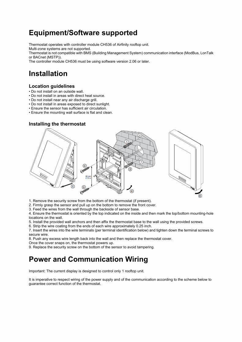
Installation Location guidelines • Do not install on an outside wall. • Do not install in areas with direct heat source. • Do not install near any air discharge grill. • Do not install in areas exposed to direct sunlight. • Ensure the sensor has sufficient air circulation. • Ensure the mounting wall surface is flat and clean. Installing the thermostat
1. Remove the security screw from the bottom of the thermostat (if present). 2. Firmly grasp the sensor and pull up on the bottom to remove the front cover. 3. Feed the wires from the wall through the backside of sensor base. 4. Ensure the thermostat is oriented by the top indicated on the inside and then mark the top/bottom mounting-hole locations on the wall. 5. Install the provided wall anchors and then affix the thermostat base to the wall using the provided screws. 6. Strip the wire coating from the ends of each wire approximately 0.25 inch. 7. Insert the wires into the wire terminals (per terminal identification below) and tighten down the terminal screws to secure wire. 8. Push any excess wire length back into the wall and then replace the thermostat cover. Once the cover snaps on, the thermostat powers up. 9. Replace the security screw on the bottom of the sensor to avoid tampering.
Power and Communication Wiring Important: The current display is designed to control only 1 rooftop unit. It is imperative to respect wiring of the power supply and of the communication according to the scheme below to guarantee correct function of the thermostat.
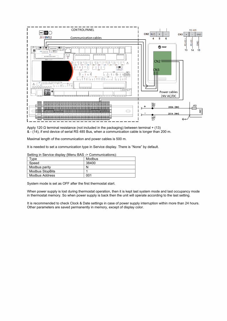
Apply 120 Ω terminal resistance (not included in the packaging) between terminal + (13) & - (14), if end device of serial RS 485 Bus, when a communication cable is longer than 200 m.
Maximal length of the communication and power cables is 500 m. It is needed to set a communication type in Service display. There is “None” by default. Setting in Service display (Menu BAS -> Communications):
Type Modbus Speed 38400 Modbus parity N Modbus StopBits 1 Modbus Address 001
System mode is set as OFF after the first thermostat start. When power supply is lost during thermostat operation, then it is kept last system mode and last occupancy mode in thermostat memory. So when power supply is back then the unit will operate according to the last setting. It is recommended to check Clock & Date settings in case of power supply interruption within more than 24 hours. Other parameters are saved permanently in memory, except of display color.

General Information All user accessible functions are easily set from home screen.

• Date To display a date in format DD/MM/YYYY
• Time To display a time in format 24 hours (HH:MM)
• Occupancy status To display an occupancy status.
• Schedule status
To display a schedule status.
• System mode status
To display a current system mode status.
• Indoor fan status
To display indoor fan status.
• Alarm button To display an alarm code.
• Override button To cancel unoccupied or occupied mode when schedule is enable in order to control the unit manually within defined period.
or Indoor fan mode button To select an indoor fan mode: Auto (Cycling) or ON (Continuous) when schedule is disable.
• System mode button
To select a mode: Auto, Heat, Cool, or Off.
Auto: System cycles between Cooling and Heating mode. Cool: System operates in Cooling mode only. Heat: System operates in Heating mode only.

Off: System is off.
• Menu button To advance to the menu.
• Cooling and heating setpoint To change a setpoint in cooling or in heating mode by a touch on the value. It is available in manual or in override control.
Other touch button
Return to previous page
Previous and next screen advancement
To advance to a day schedule.
To copy values in a schedule
To paste values in a schedule
To confirm a change.
Keyboard Esc Escape key
Backspace key
Enter key (Confirmation)
Change setting values
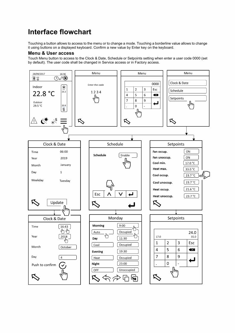
Interface flowchart Touching a button allows to access to the menu or to change a mode. Touching a borderline value allows to change it using buttons on a displayed keyboard. Confirm a new value by Enter key on the keyboard. Menu & User access Touch Menu button to access to the Clock & Date, Schedule or Setpoints setting when enter a user code 0000 (set by default). The user code shall be changed in Service access or in Factory access.

User access Menu Option Setting
Clock & Date
Time format 24 hours (HH:MM) Date format DD/MM/YYYY Date Year, Month, Day, Weekday
Schedule
Schedule Enable / Disable (Manual control) Type 7 days (Mo, Tu, We, Th, Fr, Sa, Su)
Day schedule Four time periods (Morning, Day, Evening, Night) Start time: Put a time System mode: Auto, Heat, Cool or OFF Occupancy mode: Occupied or Unoccupied
Setpoints
Occupied fan mode ON / Auto (Indoor fan)
Linked to the Schedule (Schedule enable)
Unoccupied fan mode ON / Auto (Indoor fan) Min. Cooling setpoint Min. 17 °C, Max. 35 °C Max. Heating setpoint Min. 15 °C, Max. 33 °C Occupied cool Min. 17 °C, Max. 35 °C Unoccupied cool Min. 17 °C, Max. 35 °C Occupied heat Min. 15 °C, Max. 33 °C Unoccupied heat Min. 15 °C, Max. 33 °C
Menu access Touch the 4 digits (1234) to display a keyboard and to type a code. Confirm by Enter key button of the keyboard to access the menu. Clock & Date Touch Update button to set Clock & Date.
• Time: To set time it is needed to touch values of hours HH, confirm and then to touch and set minutes MM. It has to be done separately although there is one borderline.
• Year: To set year in format YYYY. • Month: To set actual month. • Day: To set actual day in month. • Push button to confirm, then Weekday is set automatically. Need to wait 1 s (refresh time) to display
correctly the right weekday before to return on previous screen.
Schedule There are two possibilities to control the unit. With Schedule (Enable) or without schedule (Disable), which means manual control.
In case of Schedule is Enable, the unit operates in defined time schedule, system and occupancy mode. Set Enable, confirm on the keyboard and advance to Schedule sub-menu touching “Enter” button on the right bottom corner.
It is obliged to use and fill the four time periods of a day.
• Start time: Touch section of start time and set directly complete time on the displayed keyboard in format HH:MM.
• System mode: Touch section of system mode and set required system mode. • Occupancy mode: Touch section of occupancy mode and select occupied or unoccupied mode.
Occupied mode considers fresh air damper opening according to the required setting. No fresh air, fresh air damper is closed when unoccupied mode is selected. Fresh air opening setting has to be carried out in Service display.
• Touch copy button, use an arrow to go on another day and paste this schedule settings using paste button if you need repeat the same schedule.
• To browse through the day schedules use right and left arrows.

When schedule is set then the unit will operate according to the defined settings when you leave the Schedule sub-menu by touching button Return to previous page.
Setpoints In this menu the setpoints are defined for Schedule when it is Enable. To set (un)occupied cooling or heating setpoints, along with indoor fan mode (Auto/ON) and a possibility of minimal cooling setpoint and maximal heating setpoint as a global limit range value.
When the unit works in manual mode (schedule disable or override mode) then change the setpoints directly on the home screen by a touch on the value under snowflake (Cooling mode) or above heat (Heating mode). The setpoints defined for Schedule will not be rewritten. Occupancy mode is permanently set as occupied in manual or in override mode.
Minimal temperature difference about 2 K between cooling and heating setpoint is taken into account automatically.
Cooling setpoint ≥ Heating setpoint + 2 K Heating setpoint ≤ Cooling setpoint - 2 K

Menu & Service access Touch Menu button to access to the Clock & Date, Schedule, Setpoints setting, Configuration, Display or Password when enter a service code 0005. The service code shall be changed in this access or in Factory access.
No change for Clock & Date, Schedule and Setpoints options compared to the User access.
Service access
Configuration Network status Online / Offline Thermostat sensor Yes / No

Override time Min. 15 min, Max. 240 min. Factory settings Yes / No Thermostat software version no. X.X
Display Language
English, French, German Spanish, Italian, Dutch, Portuguese, Polish, Czech, Romanian
Color White, Grey, Blue, Green Backlight Min. 0 %, Max. 100 %
Password User code Possible to change. Service code Possible to change.
Configuration • Network status: Online means that connection between thermostat and unit controller module via Modbus
is operational. Offline means that thermostat does not communicate with the controller. Please check connection, wiring scheme.
• Thermostat sensor: There is possibility to control the unit by thermostat built-in temperature sensor (to set „Yes“), by space temperature local sensor („No“) or by return air temperature sensor („No“). It depends on an equipment of the unit installation.
• Override time: To define a period for override mode. • Factory settings: To put thermostat to factory settings. Put „Yes“, confirm and confirm one time again by
a touch on the button „Confirmation“. • Version: Thermostat software version is diplayed in right lower corner.
Display • Language: To select one from 10 languages available. • Color: There are 4 colors of the background available. • Backlight: To set required backlight of the screen. It is active after few seconds of no touch of the screen. • Password: User and Service code should be changed. To change a password touch the current code
(user or service), then touch 4 digits on next page, set new code on the displayed keyboard and confirm new code. The password and relevant access is active within 15 minutes. The code is required again after this period when no action is taken with thermostat.
Menu & Factory access Factory access is reserved only to a Field Service Representative for example when a customer forgets Service code.

Factory settings These parameters will be applied when you decide in Configuration menu to set the thermostat to factory settings.
Clock & Date Time 00:00 Year 2018 Month January Day 1 Schedule Schedule Disable Start time 00:00 System mode Auto Occupancy Occupied Setpoints Occupied fan mode ON Unoccupied fan mode ON Min. Cooling SP 17 °C Max. Heating SP 33 °C Occupied cool 24 °C Unoccupied cool 24 °C Occupied heat 22 °C Unoccupied heat 22 °C Configuration Thermostat sensor Yes Override time 120 min Factory settings No Display Color White Backlight 32 % Password User code 0000 Service code 0005
Thermostat menu is loaded by default in English language. When factory settings are confirmed, then actual language will not be changed.
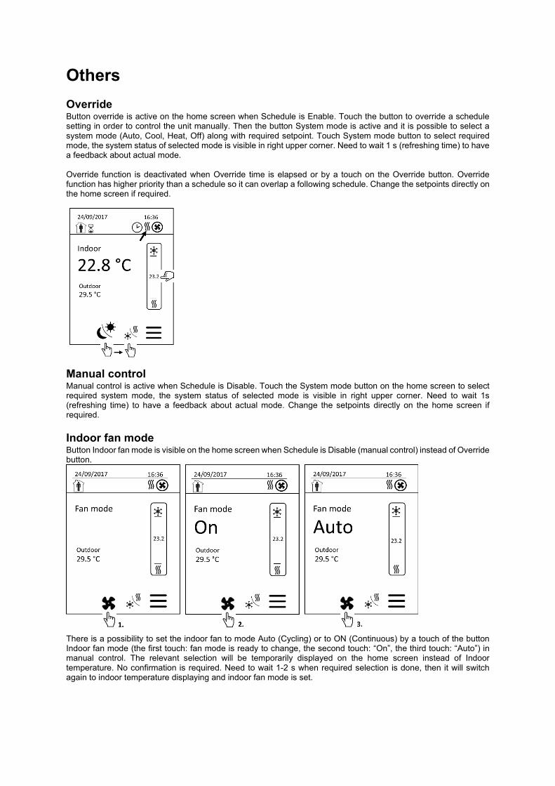
Others Override Button override is active on the home screen when Schedule is Enable. Touch the button to override a schedule setting in order to control the unit manually. Then the button System mode is active and it is possible to select a system mode (Auto, Cool, Heat, Off) along with required setpoint. Touch System mode button to select required mode, the system status of selected mode is visible in right upper corner. Need to wait 1 s (refreshing time) to have a feedback about actual mode. Override function is deactivated when Override time is elapsed or by a touch on the Override button. Override function has higher priority than a schedule so it can overlap a following schedule. Change the setpoints directly on the home screen if required.
Manual control Manual control is active when Schedule is Disable. Touch the System mode button on the home screen to select required system mode, the system status of selected mode is visible in right upper corner. Need to wait 1s (refreshing time) to have a feedback about actual mode. Change the setpoints directly on the home screen if required. Indoor fan mode Button Indoor fan mode is visible on the home screen when Schedule is Disable (manual control) instead of Override button.
There is a possibility to set the indoor fan to mode Auto (Cycling) or to ON (Continuous) by a touch of the button Indoor fan mode (the first touch: fan mode is ready to change, the second touch: “On”, the third touch: “Auto”) in manual control. The relevant selection will be temporarily displayed on the home screen instead of Indoor temperature. No confirmation is required. Need to wait 1-2 s when required selection is done, then it will switch again to indoor temperature displaying and indoor fan mode is set.

Indoor fan mode Auto (Cycling) means that the indoor fan stops when a setpoint is reached, in another case the fan runs. Mode On (Continuous) means that the fan run all the time even the setpoint is reached, except unoccupied mode and setpoint reaching, then the fan stops.
Alarm When there is an alarm active then the icon is visible. Touch the Alarm button to see the alarm code.
It is not possible to erase an alarm via thermostat. It is mandatory recommended to check an alarm cause and then to operate with Service display.

Alarm code
Alarm code Note AL06 Modbus communication fault of supply fan 3 AL07 Modbus communication fault of supply fan 2 AL08 Modbus communication fault of supply fan 1 AL16 Modbus communication fault of OD fan 2, circuit 2 AL17 Modbus communication fault of OD fan 1, circuit 2 AL18 Modbus communication fault of OD fan 2, circuit 1 AL19 Modbus communication fault of OD fan 1, circuit 1 AL28 Compressor high discharge temperature, circuit 2 AL29 Compressor high discharge temperature, circuit 1 AL36 Auxiliary heat (thermostat) fault AL39 Internal alarm of supply Fan 3 AL40 Internal alarm of supply Fan 2 AL41 Internal alarm of supply Fan 1 AL42 Outdoor fan fault, circuit 2 AL43 Outdoor fan fault, circuit 1 AL44 EXV driver not ready AL45 Low differential pressure, circuit 2 AL46 Low differential pressure, circuit 1 AL47 Low suction pressure, circuit 2 AL48 Low suction pressure, circuit 1 AL51 Compressor fault, circuit 2 AL52 Compressor fault, circuit 2 AL53 Compressor fault, circuit 1 AL54 Compressor fault, circuit 1 AL55 High pressure cut-out, circuit 2 AL56 High pressure cut-out, circuit 1 AL57 Compressor phase inversion detected AL58 FireStat signal AL59 Gas burner fault AL60 Smoke detector input fault AL61 Emergency stop signal AL62 Compressor high discharge temperature, circuit 2 AL63 Compressor high discharge temperature, circuit 1 AL64 Compressor involute pressure difference, circuit 2 AL65 Compressor involute pressure difference, circuit 1 AL67 Mechanical overloads on outdoor air damper AL68 Low superheat, circuit 2 AL69 Low superheat, circuit 1 AL70 Low suction pressure, circuit 2 AL71 Low suction pressure, circuit 1 AL72 Compressor fault, circuit 2 AL73 Compressor fault, circuit 2 AL74 Compressor fault, circuit 1 AL75 Compressor fault, circuit 1

Specification Storage conditions
Temperature -30 to 50 °C Relative humidity 0 to 75 % (non-condensing)
Operating conditions
Temperature 0 to 50 °C Power 24 VAC, 50 Hz Weight 0.34 kg Dimensions 120 x 86 x 25 mm Temperature sensor resolution ± 0.1 °C Temperature control accuracy ± 0.5 °C Temperature sensor measurement range -40 to 50 °C
Agency compliance
Safety standards LVD Directive 2006/95/EC EN60950-1:2006 / A2:2013 UL 873 CSA C22.2 No. 24-93
EMC standards
EMC Directive 2004/108/EC IEC 61326-1:2005 FCC 15 Subpart B ICES-003
Trane - by Trane Technologies (NYSE: TT), a global climate innovator - creates comfortable, energy efficient indoor environments for commercial and residential applications. For more information, please visit trane.eu or tranetechnologies.com.
Trane has a policy of continuous product and product data improvement and reserves the right to change design and specifications without notice.
BAS-SVU051B-GB_0121 ©2021 Trane Supersedes BAS-SVU051A-GB_0519