TRAJECTORY ADAPTIVE ZPET CONTROLLER …s2is.org/Issues/v6/n1/papers/paper22.pdfKeywords— Adaptive...
20
TRAJECTORY ADAPTIVE ZPET CONTROLLER WITHOUT FACTORIZATION OF ZEROS FOR NON-MINIMUM PHASE SYSTEM IN APPLICATION TO REAL-TIME DIGITAL TRACKING CONTROL OF ELECTRO-HYDRAULIC ACTUATOR Norlela Ishak 1 , Mazidah Tajjudin 1 , Hashimah Ismail 2 ,Yahaya Md Sam 3 , Ramli Adnan 1 1 Faculty of Electrical Engineering, Universiti Teknologi MARA (UiTM), 40450 Shah Alam, Selangor, Malaysia 2 Faculty of Engineering, UNISEL, Selangor, Malaysia 3 Faculty of Electrical Engineering, UTM Malaysia, Johor, Malaysia Emails: [email protected] , [email protected] , [email protected] Submitted: Sep. 22, 2013 Accepted: Jan. 10, 2013 Published: Feb. 20, 2013 Abstract— Electro-hydraulic actuators are very important tools for industrial processes because they provide linear movement, fast response and accurate positioning of heavy load. Recently, with the research and development of mathematics, control theory and basic theory of hydraulic, hydraulic control technology has been developed and has been widely used in many applications such as industrial automation and machining processes. Due to its applications, the highest performance of the electro-hydraulic actuators on position, motion or tracking is needed. Therefore, a suitable controller is required to improve the performance of the electro-hydraulic actuator. Most researchers have used advanced control approach to improve the motion or tracking control. Based on these problems, we had done a real-time digital tracking control studies on electro-hydraulic actuator using trajectory adaptive zero phase error tracking control (ZPETC) without factorization of zero polynomial algorithm. The control strategy uses a recursive least square parameters estimation that INTERNATIONAL JOURNAL ON SMART SENSING AND INTELLIGENT SYSTEMS VOL. 6, NO. 1, FEBRUARY 2013 383
-
Upload
truonglien -
Category
Documents
-
view
220 -
download
0
Transcript of TRAJECTORY ADAPTIVE ZPET CONTROLLER …s2is.org/Issues/v6/n1/papers/paper22.pdfKeywords— Adaptive...

TRAJECTORY ADAPTIVE ZPET CONTROLLER WITHOUT
FACTORIZATION OF ZEROS FOR NON-MINIMUM PHASE
SYSTEM IN APPLICATION TO REAL-TIME DIGITAL
TRACKING CONTROL OF ELECTRO-HYDRAULIC ACTUATOR
Norlela Ishak1, Mazidah Tajjudin
1, Hashimah Ismail
2,Yahaya Md Sam
3, Ramli Adnan
1
1Faculty of Electrical Engineering, Universiti Teknologi MARA (UiTM), 40450 Shah Alam,
Selangor, Malaysia 2Faculty of Engineering, UNISEL, Selangor, Malaysia
3Faculty of Electrical Engineering, UTM Malaysia, Johor, Malaysia
Emails: [email protected], [email protected], [email protected]
Submitted: Sep. 22, 2013 Accepted: Jan. 10, 2013 Published: Feb. 20, 2013
Abstract— Electro-hydraulic actuators are very important tools for industrial processes because they
provide linear movement, fast response and accurate positioning of heavy load. Recently, with the
research and development of mathematics, control theory and basic theory of hydraulic, hydraulic
control technology has been developed and has been widely used in many applications such as
industrial automation and machining processes. Due to its applications, the highest performance of
the electro-hydraulic actuators on position, motion or tracking is needed. Therefore, a suitable
controller is required to improve the performance of the electro-hydraulic actuator. Most researchers
have used advanced control approach to improve the motion or tracking control. Based on these
problems, we had done a real-time digital tracking control studies on electro-hydraulic actuator
using trajectory adaptive zero phase error tracking control (ZPETC) without factorization of zero
polynomial algorithm. The control strategy uses a recursive least square parameters estimation that
INTERNATIONAL JOURNAL ON SMART SENSING AND INTELLIGENT SYSTEMS VOL. 6, NO. 1, FEBRUARY 2013
383

was done offline prior the actual control operation by taking advantage of the available known
reference input. The experimental results obtained show significant tracking performance.
Keywords— Adaptive Control, feedforward control, tracking control, zero phase error tracking control
I. INTRODUCTION
Tracking control is very important, as the control device must follow the prescribed motion.
Many studies on applications of digital tracking control using zero phase error tracking
control (ZPETC) were done on electrical actuators [1] except hydraulic actuator [2].
Generally, hydraulic actuator has been widely used in industrial application due to its high
force-mass ratio and faster response [3, 4]. These advantages have been utilized in hydraulic
drive robot to enhance operation efficiency [5]. The natural non-linear property of hydraulic
actuator had challenged researchers in designing suitable controller for positioning control [6]
motion control and tracking control [7]
Generally, industrial hydraulic robot is using conventional PI (proportional-integral)
controller in velocity command mode. With attention to improve the motion or tracking
performance effectively, many researches have used advanced control strategies to control
hydraulic actuator [2, 8]. Based on these scenarios, this study discusses the implementation of
real-time digital tracking control of electro-hydraulic actuator using trajectory adaptive zero
phase error tracking control (ZPETC) without factorization of zeros polynomial. The model
treated was a non-minimum phase system since using faster sampling time rate to sustain
optimum information will always introduces non-minimum phase zeros in discrete-time
transfer function [9].
II. DIGITAL TRACKING CONTROL
In tracking control system, perfect tracking control is an object control strategy with zero-
tracking error [10]. Perfect tracking control can be achieved using feedforward controller,
which is the inverse transfer function of the closed-loop system [11]. This feedforward
controller is capable of cancelling all poles and zeros of the closed-loop system. This results
an overall transfer function of unity from the reference input to actual output. However, if
there is a non-minimum phase zero outside the circle, then the inverse transfer function of the
closed-loop system, which is the resulting feedforward controller, will not be stable. Thus, the
internal stability will not be guaranteed [12]. The ZPETC method that was proposed by
Norlela Ishak, Mazidah Tajjudin, Hashimah Ismail,Yahaya Md Sam, Ramli Adnan, Trajectory Adaptive ZPET Controller Without Factorization of Zeros For Non-Minimum Phase System in Application to Real-Time Digital Tracking Control of Electro-Hydraulic Actuator
384

Tomizuka [13] had attracted many researchers as one of the effective and easiest solutions to
the non-minimum phase zeros problems. Even though, the zeros of the non-minimum phase
system cannot be cancelled, by eliminating the phase error, ZPETC has shown impressive
tracking performance [14]. However, the gain error that cannot be cancelled by ZPETC will
increase for high-speed tracking that cause undesired effect to tracking performance. To
overcome these problems, many studies have been done and published to improve tracking
performance.
III. ZPETC WITHOUT FACTORIZATION OF ZEROS
The tracking control system with two-degrees-of-freedom that is consisting of feedback and
feedforward controllers is given in figure 1 [15]. In tracking control system without
feedforward controller, the reference signal continuously varying and mixed with the closed-
loop system dynamics, which make tracking error always remains. Note that the major
function of feedback controller is regulation against disturbance inputs. The feedforward
controller is required such that the reference signal can be pre-shaped by the feedforward
controller, so that more emphasis to the frequency components that were not sufficiently
handled by the feedback system can be provided [16]
Feedforward
Controller
Feedback
ControllerPlant
+
_
kukr ky
Figure 1. Two-degree-of-freedom controller
Referring to figure 1, the closed-loop transfer function of the system (without feedforward
control) can be represented by the following discrete time model:
)(
)(
)(1
11
zc
A
zc
Bdzz
clG (1)
where
anz
anazazacA ..........2
21
11
b
nz
anbzbzbobzcB ....)(2
21
11
d = time delay
INTERNATIONAL JOURNAL ON SMART SENSING AND INTELLIGENT SYSTEMS VOL. 6, NO. 1, FEBRUARY 2013
385

The function Bc (z-1
) can be factorized into minimum phase and non-minimum phase factors:
)()()(111 zcBzcBzcB (2)
where )(1zcB denotes the minimum phase factor and )(
1zcB denotes the non-minimum phase
factor. The conventional ZPETC reported in the literature [15] can be divided into three
blocks as shown in figure 2. The block diagram of feedforward ZPETC consists of the gain
compensation filter, phase compensation filter and stable inverse. Figure 3 shows the structure
of the ZPETC feedforward controller without zeros factorization. The block diagram of
feedforward ZPETC without factorization of zeros consists of the gain compensation filter,
phase compensation filter and closed-loop transfer function denominator.
kr ku)(
)(1
1
zB
zA
c
c
stable
inverse
phase
compensation
filter
gain
compensation
filter
2)1(
1
cB)(zBzF c
d
p
Figure 2. Conventional ZPETC structure block diagram
),(1
zzFg)(zBzF c
d
p )(1
zAckr ku
gain
compensation
filter
phase
compensation
filter
Closed-loop
Transfer function
denominator
Figure 3. ZPETC without factorization of zeros structure block diagram
Similar to all others ZPETC, the design mainly focused on the selection of appropriate gains
compensation filter to ensure the overall gain is unity within the frequency spectrum of
reference trajectory. To ensure the gain compensation filter, Fg does not introduces any phase
error, the same approach done by [17] and [18] will be followed. The FIR symmetric filter
was used. The filter is represented by equation:
n
k
kzkzk
zzgF0
1)(),( (3)
Norlela Ishak, Mazidah Tajjudin, Hashimah Ismail,Yahaya Md Sam, Ramli Adnan, Trajectory Adaptive ZPET Controller Without Factorization of Zeros For Non-Minimum Phase System in Application to Real-Time Digital Tracking Control of Electro-Hydraulic Actuator
386
where nα is the order of the filter. A suitable cost function to represent the error between the
desired and actual frequency response is given by Eq. (4).
20
11
l
kz
kz
n
k kzcBzcB
kJ )()()()(
(4)
The design objective here is to find a set of αk such that the cost function given by Eq. (4) is
minimized. For finite αk, Eq.(4) cannot be made zero for all frequencies. By minimizing the
cost function of Eq. (4),
10
1n
k
kz
kz
kz
cBz
cB )()()(
(5)
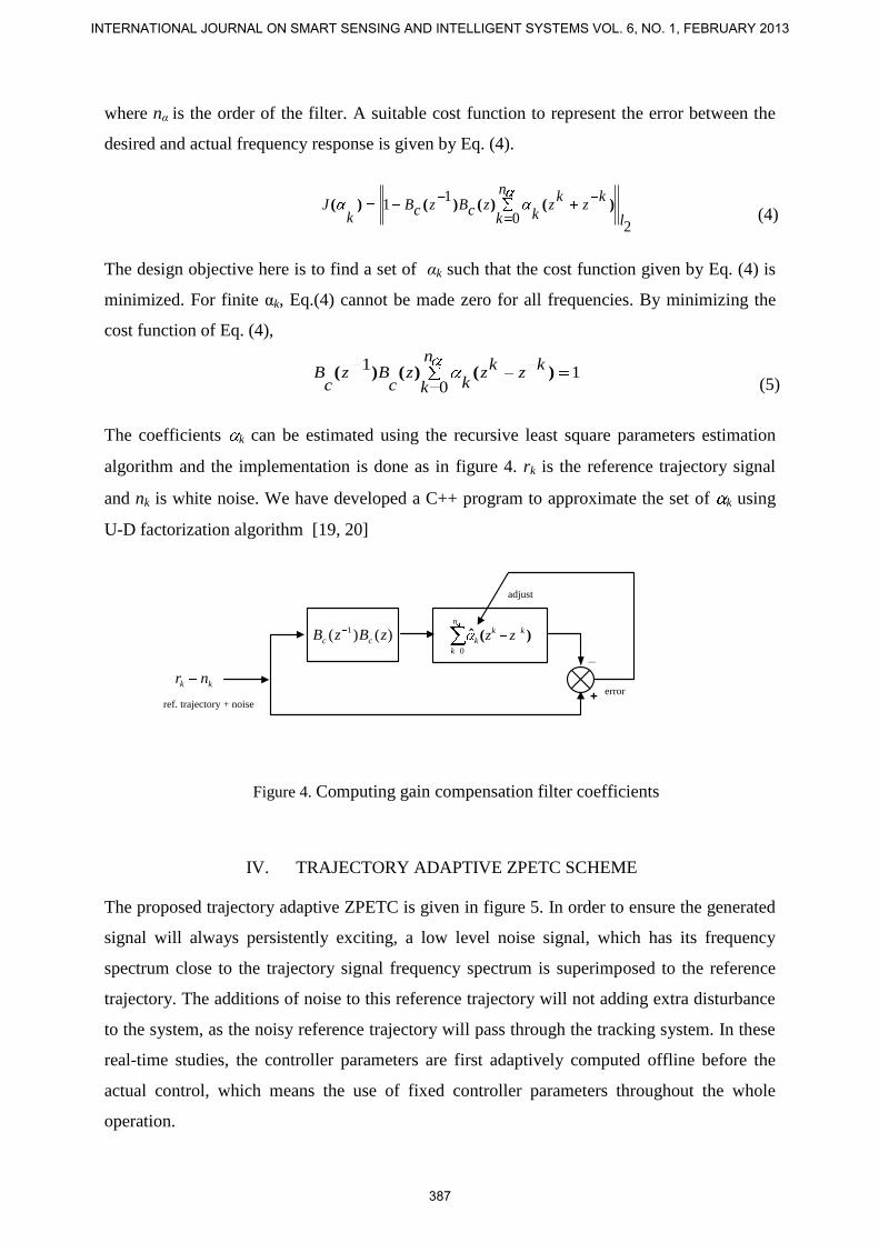
The coefficients k can be estimated using the recursive least square parameters estimation
algorithm and the implementation is done as in figure 4. rk is the reference trajectory signal
and nk is white noise. We have developed a C++ program to approximate the set of k using
U-D factorization algorithm [19, 20]
+
_
error
)()( 1 zBzB cc )(ˆ kkn
k
k zz0
adjust
kk nr
ref. trajectory + noise
IV. TRAJECTORY ADAPTIVE ZPETC SCHEME
The proposed trajectory adaptive ZPETC is given in figure 5. In order to ensure the generated
signal will always persistently exciting, a low level noise signal, which has its frequency
spectrum close to the trajectory signal frequency spectrum is superimposed to the reference
trajectory. The additions of noise to this reference trajectory will not adding extra disturbance
to the system, as the noisy reference trajectory will pass through the tracking system. In these
real-time studies, the controller parameters are first adaptively computed offline before the
actual control, which means the use of fixed controller parameters throughout the whole
operation.
Figure 4. Computing gain compensation filter coefficients
INTERNATIONAL JOURNAL ON SMART SENSING AND INTELLIGENT SYSTEMS VOL. 6, NO. 1, FEBRUARY 2013
387

+
_
error
)()( 1zAzBz cc
d
)(
)(1
1
zA
zBz
c
c
d
)()( 1 zBzB cc
adjust
ˆ
kr kyku
kn+
+kk nr
reference
trajectory
noise
)(ˆ kkn
k
k zz0
)(ˆ kkn
k
k zz0
V. EXPERIMENTAL SET-UP
The experimental equipment that used in these real-time studies is an electro-hydraulic system
that is shown in figure 4. The hydraulic cylinder was held in vertical position. This is a very
challenging problem as effect of gravity is trivial. The electro-hydraulic system consists of
single-ended cylinder type of actuator. The bidirectional cylinder has 150 mm stroke length;
40 mm bore size and 25 mm rod size. The wire displacement sensor is mounted at the top of
cylinder rod. The pressurized fluid flow is control by electronic control valve.
Figure 6. Electro Hydraulic Actuator
The schematic diagram of complete experimental set-up is given in Figure 7. The interfacing
between the computer and plant was done using Matlab Real-Time Workshop via Advantech
PCI-1716 interface card.
Figure 5. Trajectory adaptive ZPETC structure
Norlela Ishak, Mazidah Tajjudin, Hashimah Ismail,Yahaya Md Sam, Ramli Adnan, Trajectory Adaptive ZPET Controller Without Factorization of Zeros For Non-Minimum Phase System in Application to Real-Time Digital Tracking Control of Electro-Hydraulic Actuator
388

Data Acquisition
Board
PCI1716
Position
Transduser
Bidirectional
Cylinder
Proportional
Valve
VI. PLANT MODEL
The plant model that used in these studies was obtained through open-loop experiment on the
Electro-hydraulic system of figure 6. The open-loop transfer function of the plant was
approximated using Matlab System Identification Toolbox. The signal given in figure 8 was
used as an input signal to the plant for model identification. The signal was generated using
three different frequencies based on Eq. (6) and represented by Eq. (7).
p
ikstii
aku1
cos)( (6)
Vin (k) = 2 Cos 0.3 tsk + 2 Cos 4 tsk + Cos 6 tsk
(7)
where ai is the amplitude, i is the frequency (rad/sec), ts is the sampling time (sec) and k is
integer. From Eq. (7), when using three different frequencies for input signal, the model that
can be obtained is limited to second and third order only. Higher-orders model may produce
unstable output. In these studies, the third-order ARX331 model with input-output signals
sampled at 50ms was selected to represent the nearest model of true plant.
Figure 7. Experimental setup for electro-hydraulic system
INTERNATIONAL JOURNAL ON SMART SENSING AND INTELLIGENT SYSTEMS VOL. 6, NO. 1, FEBRUARY 2013
389

The output signal of the plant obtained using the input signal of figure 5 and sampled at 50
ms, is given in figure 9. The input and output signals of Figure 8 and Figure 9 were divided
into two parts, i.e. (500-1000) samples and (1001-1500) samples. The first part of the input –
output signals was used to obtain the plant model and the second part of the input-output
signals was used to validate the obtained model.
Using Matlab System Identification Toolbox, the first part of the input-output signal produces
a plant model, ARX331 in the form of discrete-time open-loop transfer function as follows:
3z1861.02z3938.01z5800.11
3z0088.02z0037.01z0087.0
)1z(o
A
)1z(o
B (8)
From Eq. (8), its can be simplified as
Figure 9. Output signal of the plant using 50 ms sampling time
Figure 8. Input signals for model identification
Norlela Ishak, Mazidah Tajjudin, Hashimah Ismail,Yahaya Md Sam, Ramli Adnan, Trajectory Adaptive ZPET Controller Without Factorization of Zeros For Non-Minimum Phase System in Application to Real-Time Digital Tracking Control of Electro-Hydraulic Actuator
390

3z1861.02z3938.01z5800.11
)2z0148.11z4232.01(1z0087.0
)1z(o
A
)1z(o
B (9)
From Eq. (9), the zeros polynomial is given by
2z0148.11z4232.01)1z(c
B (10)
2z0148.1z4232.01)z(c
B
When Eq. (10) is factorized, the locations of zero are at z = 0.8178 and z = -1.2410. This
means that the model obtained is a non-minimum phase model with a zero situated outside the
unity circle. A non-minimum phase model can be obtained using small sampling time whereas
minimum phase model can be obtained using larger values of sampling time [17]. The pole-
zero plot of Eq. (10) is given in figure 10.
Figure 10. Pole-zero plot of Eq. (10)
The second part of input-output signals was used to validate the obtained model of Eq. (8).
The second part of the input signal was used as an input to the model and the output from the
model was compared with the second part of the output signal. The result can be seen from
figure 11. Using model selection criterions, the following information were obtained:
Best Fit : 89 %
Loss Function : 3.292 e-005
Akaike’s Final Prediction Error, FPE: 3.371 e-005
-2 -1 0 1 2-2
-1
0
1
2
Poles (x) and Zeros (o)
50ms
INTERNATIONAL JOURNAL ON SMART SENSING AND INTELLIGENT SYSTEMS VOL. 6, NO. 1, FEBRUARY 2013
391

Based on the smallest values criteria of FPE and Best Fit of 89 %, this model can be accepted.
VII. REAL TIME STUDIES
The tracking control structure that used for real-time studies is shown in figure 12. The
structure is divided into two parts: feed-forward control; and feedback control. The feed-
forward control block is using the trajectory ZPETC where the optimum controller parameters
are obtained offline using recursive least square (RLS) method. The feedback control block is
using pole-placement method to determine its controller parameters.
+
_ku )(
11zF )(
)(1
1
zA
zB
o
o
)( 1zG
ky
fKkrReference
TrajectoryOutput
n
k
kk
k zz0
)(ˆ )( 1zAc)(zBz c
d
Feedforward
Control
Feedback
Control
Figure 12. Tracking structure for real-time studies
VIII. FEEDBACK CONTROL SYSTEM
The feedback control system for the proposed trajectory ZPETC system is given in figure 13.
The controller was designed using pole-placement method.
+
_ku )(
11zF )(
)(1
1
zA
zB
o
o
)( 1zG
kyfK
Figure 13. Feedback controller using pole-placement method.
1000 1050 1100 1150 1200 1250 1300 1350 1400 1450 15001
2
3
4
5
6
7
Time Steps
Dis
pla
ce
me
nt
(in
)
Model
Plant
Figure 11. Comparison between the model and plant output signal
signal time
Norlela Ishak, Mazidah Tajjudin, Hashimah Ismail,Yahaya Md Sam, Ramli Adnan, Trajectory Adaptive ZPET Controller Without Factorization of Zeros For Non-Minimum Phase System in Application to Real-Time Digital Tracking Control of Electro-Hydraulic Actuator
392
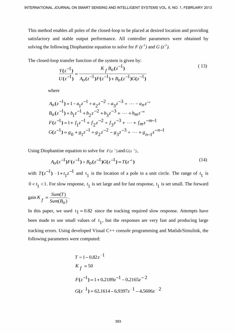
This method enables all poles of the closed-loop to be placed at desired location and providing
satisfactory and stable output performance. All controller parameters were obtained by
solving the following Diophantine equation to solve for F (z-1
) and G (z-1
).
The closed-loop transfer function of the system is given by:
)()()()(
)(
)(
)(
1111
1
1
1
zGzoBzFzoA
zoBf
K
zU
zY
( 13)
where
nznazazazazoA )( 33
22
11
11
mzmbzbzbzbzoB )( 33
22
11
1
133
22
11
11 mzmfzfzfzfzF )(
11
33
22
110
1 nzn
gzgzgzggzG )(
Using Diophantine equation to solve for )( 1zF and )( 1zG ,
)()()()()(11111 zTzGzoBzFzoA (14)
with 11
11 ztzT )( and 1
t is the location of a pole in a unit circle. The range of 1t is
11
0 t . For slow response, 1t is set large and for fast response,
1t is set small. The forward
gain)(
)(
oBSum
TSum
fK .
In this paper, we used 82.01t since the tracking required slow response. Attempts have
been made to use small values of 1
t , but the responses are very fast and producing large
tracking errors. Using developed Visual C++ console programming and Matlab/Simulink, the
following parameters were computed:
18201 zT .
50f
K
22165012189011 zzzF ..)(
2560641939761614621 zzzG ...)(
INTERNATIONAL JOURNAL ON SMART SENSING AND INTELLIGENT SYSTEMS VOL. 6, NO. 1, FEBRUARY 2013
393

IX. RESULTS AND DISCUSSION
In this section, the real-time results were analyzed to show the effectiveness of the designed
controller. The reference trajectory signal of figure 14 was used in the real-time studies of
non-minimum phase model. As we can observe from that figure, for time steps of 0-350, low
frequencies are used. But, for the 350-600 time steps, higher frequencies are used. The shape
of this signal was purposely chosen to demonstrate the ability of the controller to track the
trajectory with changing frequency components.
Figure 14. Reference trajectory signals, rk
Firstly, a feedback control system using pole-placement method without feedforward, ZPETC
controller was applied to observe its tracking performance. A high root mean square tracking
error of 0.0907 inch was obtained. We can observe in figure 15(a), that the plant tracking is
almost perfect as the overlapping between the two signals is difficult to been seen. Their
different can only be seen when the view of 350-600 time steps is enlarge as given in figure
15(d). From figure 15(b), we can observe that for 300-600 time steps, high tracking error
occurred when there are changes in dominant frequencies of reference trajectory. Therefore,
feedforward controller is required to pre-shape the reference signal so that more emphasis to
the frequency components that were not sufficiently handle by the feedback system can be
provided.
0 150 200 250 300 350 400 450 500 550 6000
1
2
3
4
5
6
Time Steps
Dis
pla
cem
ent
(inch)
Norlela Ishak, Mazidah Tajjudin, Hashimah Ismail,Yahaya Md Sam, Ramli Adnan, Trajectory Adaptive ZPET Controller Without Factorization of Zeros For Non-Minimum Phase System in Application to Real-Time Digital Tracking Control of Electro-Hydraulic Actuator
394
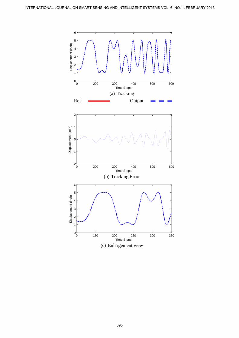
(a) Tracking
(b) Tracking Error
(c) Enlargement view
0 200 300 400 500 6000
1
2
3
4
5
6
Time Steps
Dis
pla
cem
ent
(inch)
0 200 300 400 500 600-2
-1
0
1
2
Time Steps
Dis
pla
cem
ent
(inch)
0 150 200 250 300 3500
1
2
3
4
5
6
Time Steps
Dis
pla
cem
ent
(inch)
Ref Output
INTERNATIONAL JOURNAL ON SMART SENSING AND INTELLIGENT SYSTEMS VOL. 6, NO. 1, FEBRUARY 2013
395

(d) Enlargement View
Figure 15. Experimental results using feedback control system with RMSE 0.0907 inch.
Next, we apply feedforward, ZPETC controller proposed by Tomizuka [13] . The obtained
experimental result is given in figure 16 with r.m.s tracking error of 0.0812 inch. If we
compare this tracking performance with the one given in figure 15, it is obvious that the
tracking error has been reduced. From figure 16(a), the plant tracking is almost perfect as the
overlapping between the two signals is difficult to be seen. From 16(b), and figure 16(c, d)
that have been enlarge, tracking error improved compare with the one given in figure 15(b)
and 15(d). This is because the controller was able to approximate the overall system transfer
function close to unity for all frequencies. Therefore for accurate position tracking, it requires
feedforward control. However, the gain error that cannot be cancelled by ZPETC will increase
for high-speed tracking that cause undesired effect to tracking performance.
(a) Tracking
350 400 450 500 550 6000
1
2
3
4
5
6
Time Steps
Dis
pla
cem
ent
(inch)
0 200 300 400 500 6000
1
2
3
4
5
6
Time Steps
Dis
pla
cem
ent
(inch)
Ref Output
Norlela Ishak, Mazidah Tajjudin, Hashimah Ismail,Yahaya Md Sam, Ramli Adnan, Trajectory Adaptive ZPET Controller Without Factorization of Zeros For Non-Minimum Phase System in Application to Real-Time Digital Tracking Control of Electro-Hydraulic Actuator
396

(b) Tracking Error
(c) Enlargement View
(d) Enlargement View
Figure 16. Experimental results using Tomizuka method with RMSE 0.0812 inch
With objective to reduce tracking error further, we apply the propose ZPETC with fixed
controller parameters obtained by adaptive method given in figure 4. In order to determine the
correct filter order to be used in the trajectory ZPETC, the frequency response of the ZPETC
given in figure 3 are plotted using the transfer functions of plant model. The resulting
0 200 300 400 500 600-2
-1
0
1
2
Time Steps
Dis
pla
cem
ent
Err
or
(inch)
0 150 200 250 300 3500
1
2
3
4
5
6
Time Steps
Dis
pla
cem
ent
(inch)
350 400 450 500 550 6000
1
2
3
4
5
6
Time Steps
Dis
pla
cem
ent
(inch)
INTERNATIONAL JOURNAL ON SMART SENSING AND INTELLIGENT SYSTEMS VOL. 6, NO. 1, FEBRUARY 2013
397

0 0.5 1 1.5 2 2.5 30.6
0.8
1
1.2
Frequency (rad/s)
Ga
in
n10
n20
n30
frequency response is given in figure 17. From figure 17, it can be observed that an
approximate overall unity gain can be achieved when using filter order, N≥20.
Figure 17. Frequency response of 10th
,20th
and 30th
order of proposed ZPETC
The real-time experimental results are shown in figure 18, figure 19 and figure 20. From the
graph, it is observed that the tracking error is very flat for N≥20. The root mean square (RMS)
of tracking error for N=10 is 0.2106 inch, for N=20 is 0.0282 inch and for N=30 is 0.0030
inch. It can be deduced that the higher the N, the better will be the root mean square of
tracking error. From figure 18, we can observe that high tracking error had occured. These are
due to the approximate controller parameters are still in the process of adaptation and not yet
converged. The problem of longer converging time can be shorten when using higher filter
order, N. The effect can be observed from the real-time result given in figure 19 dan 20, when
the filter order is increase. The resulting rms tracking error is much better than the tracking
error when using conventional ZPETC that the one given in figure 16. This is because higher
controller order can produce an overall transfer function very much closer to unity due to
larger degree of freedom.
Norlela Ishak, Mazidah Tajjudin, Hashimah Ismail,Yahaya Md Sam, Ramli Adnan, Trajectory Adaptive ZPET Controller Without Factorization of Zeros For Non-Minimum Phase System in Application to Real-Time Digital Tracking Control of Electro-Hydraulic Actuator
398

Figure 18. Experimental result using 10th
order proposed ZPETC with RMSE 0.2106 inch
Figure 19. Experimental result using 20
th order proposed ZPETC with RMSE 0.0282 inch
0 200 300 400 500 6000
1
2
3
4
5
6
Time Steps
Dis
pla
cem
ent
(inch)
0 200 300 400 500 600-2
-1
0
1
2
Time Steps
Dis
pla
cem
ent
Err
or
(inch)
0 200 300 400 500 600
1
2
3
4
5
6
Time Steps
Dis
pla
cem
ent
(inch)
0 200 300 400 500 600-2
-1
0
1
2
Time Steps
Dis
pla
cem
ent
Err
or
(inch)
INTERNATIONAL JOURNAL ON SMART SENSING AND INTELLIGENT SYSTEMS VOL. 6, NO. 1, FEBRUARY 2013
399

Figure 20. Experimental result using 30th
order proposed ZPETC with RMSE 0.0030 inch
X. CONCLUSIONS
The implementation and experimental results of real-time digital tracking control of hydraulic
actuator using the proposed controller design based on trajectory ZPETC without factorization
of zeros polynomial has been presented. Experimental results show that the proposed method
can provide satisfactory tracking performances to a non-minimum phase hydraulic actuator
system. Experimental results show good tracking performances when higher order filter was
used in the design. A much smaller tracking error cannot be achieved due to plant-model
mismatch and electronic valve open-close capability. Hence, the implementation of the
proposed controller on the electro-hydraulic actuator system can offer a significant
improvement in modern equipment positioning applications.
ACKNOWLEDGMENT
The authors would like to thank and acknowledge the FRGS-RMI-UiTM (600-RMI/ST/FRGS
5/3/Fst(85/2010) and FKE-UiTM for financial support of this research.
0 200 300 400 500 600-2
-1
0
1
2
Time Steps
Dis
pla
cem
ent
Err
or
(inch)
err-rls-n30-sim
0 200 300 400 500 6000
1
2
3
4
5
6
Time Steps
Dis
pla
cem
ent
(inch)
0 200 300 400 500 600-2
-1
0
1
2
Time Steps
Dis
pla
cem
ent
Err
or
(inch)
Norlela Ishak, Mazidah Tajjudin, Hashimah Ismail,Yahaya Md Sam, Ramli Adnan, Trajectory Adaptive ZPET Controller Without Factorization of Zeros For Non-Minimum Phase System in Application to Real-Time Digital Tracking Control of Electro-Hydraulic Actuator
400

REFERENCES
[1] H. Chen-Chou, W. An-Ping, and H. Pau-Lo, "CAN-based motion control design," in
SICE 2003 Annual Conference, vol. 3, pp. 2504-2509, 2003
[2] T.-C. Tsao and M. Tomizuka, "Robust Adaptive and Repetitive Digital Tracking
Control and Application to a Hydraulic Servo for Noncircular Machining," Journal of
Dynamic Systems, Measurement, and Control, vol. 116, pp. 24-32, 1994.
[3] H.-M. Chen, J.-C. Renn, and J.-P. Su, "Sliding mode control with varying boundary
layers for an electro-hydraulic position servo system," The International Journal of
Advanced Manufacturing Technology, vol. 26, pp. 117-123, 2005.
[4] S. Junpeng, W. Zhongwen, L. Jianying, and H. Guihua, "Model Identification and
Control of Electro-hydraulic Position Servo System," in Intelligent Human-Machine
Systems and Cybernetics, 2009. IHMSC '09. International Conference on, pp. 210-
213,2009
[5] M. Namvar and F. Aghili, "A Combined Scheme for Identification and Robust Torque
Control of Hydraulic Actuators," Journal of Dynamic Systems, Measurement, and
Control, vol. 125, pp. 595-606, 2003.
[6] C. Kaddissi, J. P. Kenne, and M. Saad, "Identification and Real-Time Control of an
Electrohydraulic Servo System Based on Nonlinear Backstepping," Mechatronics,
IEEE/ASME Transactions on, vol. 12, pp. 12-22, 2007.
[7] W.-H. Zhu and J.-C. Piedboeuf, "Adaptive Output Force Tracking Control of
Hydraulic Cylinders With Applications to Robot Manipulators," Journal of Dynamic
Systems, Measurement, and Control, vol. 127, pp. 206-217, 2005.
[8] B. Eryilmaz and B. H. Wilson, "Improved Tracking Control of Hydraulic Systems,"
Journal of Dynamic Systems, Measurement, and Control, vol. 123, pp. 457-462, 2001.
[9] K. J. Astrom, P. Hagander, and J. Sternby, "Zeros of sampled systems," in Decision
and Control including the Symposium on Adaptive Processes, 19th IEEE Conference
on, 1980, pp. 1077-1081, 1980
[10] B. Haack and M. Tomizuka, "The Effect of Adding Zeroes to Feedforward
Controllers," Journal of Dynamic Systems, Measurement, and Control, vol. 113, pp. 6-
10, 1991.
[11] H. Fujimoto and B. Yao, "High performance motion control of linear motors based on
multirate adaptive robust control," in Advanced Motion Control, 2004. AMC '04. The
8th IEEE International Workshop on, pp. 547-552,2004
[12] J. Lu, F. Li, K. Ishihata, and T. Yahagi, "A perfect tracking control design method
using multirate control in discrete-time systems," in Power Electronics and Motion
Control Conference, 2004. IPEMC 2004. The 4th International, vol 3, pp. 1607-1612,
2004
[13] M. Tomizuka, "Zero phase error tracking algorithm for digital control," ASME Journal
of Dynamic Systems, Meas and Control, vol. 109, pp. 6-10, 1987.
[14] H.-S. Park, P. H. Chang, and D. Y. Lee, "Concurrent Design of Continuous Zero
Phase Error Tracking Controller and Sinusoidal Trajectory for Improved Tracking
Control," Journal of Dynamic Systems, Measurement, and Control, vol. 123, pp. 127-
129, 2001.
[15] M. Tomizuka, "On the Design of Digital Tracking Controllers," Journal of Dynamic
Systems, Measurement, and Control, vol. 115, pp. 412-418, 1993.
[16] R. C. Ko, M. C. Good, and S. K. Holgamuge, "Adaptive calibration of feedforward
controllers for laser profiling machines," in Information, Decision and Control, 1999.
IDC 99. Proceedings. pp. 157-162, 1999
INTERNATIONAL JOURNAL ON SMART SENSING AND INTELLIGENT SYSTEMS VOL. 6, NO. 1, FEBRUARY 2013
401

[17] Y. Syh-Shiuh and H. Pau-Lo, "An optimal and adaptive design of the feedforward
motion controller," Mechatronics, IEEE/ASME Transactions on, vol. 4, pp. 428-439,
1999.
[18] M. M. Mustafa, "Trajectory-adaptive digital tracking controllers for non-minimum
phase systems without factorisation of zeros," Control Theory and Applications, IEE
Proceedings -, vol. 149, pp. 157-162, 2002.
[19] Z. Youmin and X. R. Li, "A fast U-D factorization-based learning algorithm with
applications to nonlinear system modeling and identification," Neural Networks, IEEE
Transactions on, vol. 10, pp. 930-938, 1999.
[20] A. W. Ordys, "Adaptive control systems, R. Isermann, K. H. Lachmann and D. Matko,
Prentice-Hall International, Hemel Hempstead, U.K., 1992, ISBN 0-13-005414-3,
XVIII + 541 pp., £45.00," International Journal of Adaptive Control and Signal
Processing, vol. 6, pp. 518-519, 1992.
Norlela Ishak, Mazidah Tajjudin, Hashimah Ismail,Yahaya Md Sam, Ramli Adnan, Trajectory Adaptive ZPET Controller Without Factorization of Zeros For Non-Minimum Phase System in Application to Real-Time Digital Tracking Control of Electro-Hydraulic Actuator
402