Training Guide Hole Machining - cadfamily.com€¦ · Training Guide Hole Machining . ... Tab 3-17...
134
Training Guide Hole Machining
Transcript of Training Guide Hole Machining - cadfamily.com€¦ · Training Guide Hole Machining . ... Tab 3-17...
Training Guide
Hole Machining


Table of Contents
Copyright 2014 © Sescoi International i SESINT_EN_DRILL 120514 - Hole Machining
Table of Contents
1 Training Guide Objectives 1-1
2 Introduction to Hole Machining 2-1
3 Automatic Feature Recognition 3-1
3.1 Drilling Function Parameters 3-3
3.1.1 Drilling Function Parameters - Tolerances Tab 3-4 3.1.2 Drilling Function Parameters - Colors Tab 3-8 3.1.3 Drilling Function Parameters - Recognition Options Tab 3-10 3.1.4 Drilling Function Parameters - Other Options Tab 3-11 3.1.5 Drilling Function Parameters - Other Holes Tab 3-13 3.1.6 Drilling Function Parameters - Strategy Tab 3-15 3.1.7 Drilling Function Parameters - Tapping Tab 3-17
3.2 Moving Recognized Features 3-19
4 Automatic Hole Machining 4-1
4.1 Programming your First Hole Machining Toolpath 4-1
4.2 Preview of the FTD File 4-2
4.3 Configuration Files required for Automatic Hole Machining 4-5
4.3.1 Features Definition File (*.ftd) 4-5 4.3.2 Strategy Configuration File (*.fts) 4-8 4.3.3 Tool Configuration File (*.ftt) 4-15
4.4 Practicing: Machine Conical Holes 4-26
4.5 Hole Machining with Point Files 4-30
4.5.1 WorkNC Features: Points at Hole Top 4-30 4.5.2 WorkNC Features: Points at bottom of Holes 4-35
4.6 Create Automatic Hole Machining Toolpath from a 2D File 4-37
4.7 User-defined Strategies for Automatic Hole Machining 4-42
4.7.1 Declaring additional Types of Holes 4-43 4.7.2 Creating a User-defined Strategy 4-46 4.7.3 Creating Tools for Sub-strategies 4-54 4.7.4 Checking the Use of Sub-Strategies 4-55
4.8 Examples of Tool and Strategy Files for Contour Tapping Operations 4-57
4.9 Thread Milling by Contouring with the Tapping/Threading Toolpath 4-62
5 Interactive Hole Machining 5-1
5.1 Manual Hole Machining 5-1

Table of Contents
SESINT_EN_DRILL 120514 - Hole Machining ii Copyright 2014 © Sescoi International
5.1.1 Defining a Hole Machining Strategy and Calculating Toolpath 5-3 5.1.2 Practicing: Defining a Manual Thread Milling Strategy 5-8
5.2 Auto User Strategy 5-13
5.2.1 Defining Recognition Rules 5-13 5.2.2 Applying a Type Rule 5-18 5.2.3 Defining a Strategy to Machine the Recognized Features 5-19 5.2.4 Managing Strategies 5-25 5.2.5 Creating Features from Point Selection 5-28 5.2.6 Tapping Attributes 5-31

Training Guide Objectives 1
Copyright 2014 © Sescoi International 1-1 SESINT_EN_DRILL 120514 - Hole Machining
1 Training Guide Objectives This training session and its related manual require that the user has a good working knowledge of WorkNC. The particular examples given in the manual may not concern all users or applications of WorkNC. The main goal of this manual is to provide users with the tools (knowledge and concepts) that may be applied to specific problems that they may encounter when machining holes.
At the end of the training session, you should be able to:
Change feature recognition parameters to make sure that holes are correctly recognized Program an Automatic Hole Machining toolpath Create his own strategy and tool files to meet his own requirements Program a Manual Hole Machining toolpath Program a toolpath using the Auto User Strategy
MATERIALS USED IN THIS TRAINING GUIDE...
Parts used for illustrations Workzones Other materials
features_01.xdw Thread_milling strategy_example.fts
angled_holes.xdw Thread_milling_v23 simple_thread.fts
features_holes2.xdw Pumpe simple_thread_tapper_inside.fts
features_holes3.xdw Angle_holes_v23 2D_boring.dxf features_conical.xdw Hole_drilling_specific.xdw
STANDARD CONFIGURATION
This training guide also refers to standard strategy and tool files delivered with the WorkNC standard configuration: NOTE
Simple FTS and FTT files Try_to_do_all FTS and FTT files
This training manual is not a comprehensive manual. For more help you can go to our Online Help or read our other training manuals.


Introduction to Hole Machining 2
Copyright 2014 © Sescoi International 2-1 SESINT_EN_DRILL 120514 - Hole Machining
2 Introduction to Hole Machining WorkNC includes a hole machining toolpath which you can use for drilling, spot facing, reaming, tapping, etc. The position and definition of the holes can be set manually in WorkNC or automatically by completing a feature recognition.
Once you have defined the holes to be machined - either manually or after an automatic feature recognition - you need to specify the tools and machining strategies you want to use. Again, this process can be automatic or be completed in an interactive manner.
In any case, remember the following:
Programming an automatic hole machining toolpath requires defining three types of data:
the holes to be machined, the list of available tools and the machining strategy to apply to each type of hole.
Hole Machining Toolpath Parameters
Toolpath calculations will generate several toolpaths, one for each hole function.

2 Introduction to Hole Machining
SESINT_EN_DRILL 120514 - Hole Machining 2-2 Copyright 2014 © Sescoi International
Recalculated Toolpath
Each toolpath can be viewed individually. The post-processor allows the generation of ISO codes (machine cycles) for the different
types of holes.
SUMMARY OF THE HOLE MACHINING PROCESS
Workflow for Automatic or Manual Drilling Management
Automatic Feature Recognition Drilling Function Parameters 3
Copyright 2014 © Sescoi International 3-1 SESINT_EN_DRILL 120514 - Hole Machining
3 Automatic Feature Recognition 1. Create a workzone with the features_01.xdw file.
This is a simple part with two through holes.
2. Click on Functions in the text menu bar and select Drilling Manager in the Drilling Manager menu.
Or right click on the part in the Viewing Area and select Drilling Manager.
The Drilling Manager is displayed.
Drilling Manager
3. To make sure that we will use default parameters, click on the Parameters button to display the Drilling Function Parameters dialog box.

3 Automatic Feature Recognition Drilling Function Parameters
SESINT_EN_DRILL 120514 - Hole Machining 3-2 Copyright 2014 © Sescoi International
Drilling Function Parameters Dialog Box
4. Click on the Default button and click OK to validate and exit the dialog box.
5. Click on the Sort button and press the [Ctrl]+[A] keys to select the whole part.
6. Right click in the Viewing Area or click on the icon to validate.
Features List in the Drilling Manager

Automatic Feature Recognition Drilling Function Parameters 3
Copyright 2014 © Sescoi International 3-3 SESINT_EN_DRILL 120514 - Hole Machining
The dialog box shows all the features that have been recognized. The feature type is automatically specified in accordance with the color code defined in the Drilling Function Parameters dialog box. Here, the red color corresponds to drill holes. Four drill holes were automatically recognized: two with a 10mm diameter and two others with a 16mm diameter.
See also... Applying a Type Rule [ 5-18] Defining Recognition Rules [ 5-13]
3.1 Drilling Function Parameters
Drilling Function Parameters Dialog Box
This dialog box contains a number of tabs, each one grouping together a number of parameters for hole recognition and feature definition.
The upper section of the dialog box is always visible and allows the user to define different sets of parameters which may be stored as a Configuration.
Current Configuration
Informs the user which Configuration is currently the active one.
Select a Configuration
This drop-down list allows the user to select a Configuration among the available ones.

3 Automatic Feature Recognition Drilling Function Parameters
SESINT_EN_DRILL 120514 - Hole Machining 3-4 Copyright 2014 © Sescoi International
Clicking on this icon allows you to define a new Drilling Configuration.
1. Click on this icon to display the following dialog box:
2. Enter a Name for the new Configuration.
3. Enter a descriptive in the Comment field. This Comment is displayed in an information box when you hold the mouse cursor over the Configuration Name in the Select Configuration drop-down list.
4. Click on OK to validate.
Click on this icon to display a dialog box which allows you to edit the Configuration name and description.
Click on this icon to delete the currently selected Drilling Configuration. A message box pops up asking you to confirm the deletion.
Click on this icon to make the Configuration newly selected in the drop-down list the current one.
COMMAND BUTTONS
The command buttons at the bottom of the dialog box allow you to do the following:
Default Click on this button to restore the default settings. Save Click on this button to save your customized settings for a given configuration. The dialog box stays
open allowing you to continue working on the Drilling Function Parameters. OK Click on this button to save the current settings and to close the dialog box. Cancel Click on this button to close the dialog box without saving the most recent parameter modifications.
3.1.1 Drilling Function Parameters - Tolerances Tab The Tolerances tab in the Drilling Function Parameters dialog box allows you to specify a number of hole detection tolerances.

Automatic Feature Recognition Drilling Function Parameters 3
Copyright 2014 © Sescoi International 3-5 SESINT_EN_DRILL 120514 - Hole Machining
Drilling Function Parameters - Tolerances Tab
DRILL TOLERANCES Decimal Places Allows you to define the number of decimal places to be used to indicate the diameter,
depth, etc. values in the hole list and drill feature list control panel. The default value is 2, which is used if you activate the Automatic option.
Hole Detection Tolerance
Defines the tolerance value for hole detection. This is to determine whether the surface shape is a cylinder or not.
Same Point Tolerance
Defines the tolerance value to detect if two 3D points are identical.
Same Angle Tolerance
Defines the tolerance value to detect if two hole angles are identical (in degrees). It is also used to close an open cylinder.
Coaxial Tolerance
Tolerance for the projection of the 2 cylinder extremities. This is to verify if several holes have the same axis and if several surfaces belong to the same hole. This value works together with the Same Angle Tolerance.
Same Radius Tolerance
Tolerance between radii. This tolerance is used to check whether several surfaces around the hole have the same curvature radius and whether different holes have the same radius (or diameter). In this case, holes with identical radii are written to the same feature. E.g. for counter bores, one would not want the counter bore and hole to be considered as one hole. A lower tolerance here will make a counter bore as two operations or two holes.
Radius Approximation
Rounding up of the radii values on transfer of the data to WorkNC. E.g. if this value is set to 0.01 a diameter of 9.995 will be output as 10
3 Automatic Feature Recognition Drilling Function Parameters
SESINT_EN_DRILL 120514 - Hole Machining 3-6 Copyright 2014 © Sescoi International
Cylinder Detection Minimum Angle
This parameter allows you to determine which open cylinders will be recognized as drills. In the following example, this value is set to 300. In this case, the left hole will be recognized, the right one will be ignored.
Example Cylinder Detection Minimum Angle
Be careful when fixing this value. Example:
4 radii will be detected if: Min. angle = 90° or less
2 radii will be detected if: Min. angle = 180° or less
Ignore Bevel Height on Flat Ends (Angle)
Allows you to select whether the bevel height is taken into account on flat ends and to specify the corresponding angle.
Head Distance Tolerance
This option allows you to specify the required clearance for the machine head to enter the space between walls in order to machine the drillings inside the part as it is shown in the following example:

Automatic Feature Recognition Drilling Function Parameters 3
Copyright 2014 © Sescoi International 3-7 SESINT_EN_DRILL 120514 - Hole Machining
Through Distance Tolerance
Minimum distance (see A in the image below) that must be left free beyond the end of the hole for it to be considered as a through hole. If you enter 10mm here, there must be at least 10mm between the end of the hole and the next surface below for the hole to be processed as a through hole.
This also applies for holes with a bottom bevel:
In this example, the next blue surface is far enough to process the hole as a through hole as shown on the right side of the illustration. If the distance is less than the defined tolerance, it is processed according to the Blind Hole Bottom Bevels parameter in the Other Options tab [ 3-13] .
HOLE AXIS ORIENTATION
This section allows you to detect features according to their orientation.
Orientation Mode Axis Only
This option only detects the features whose drill axis orientation follows the Z axis of the active axis system.
In the example above, the application has only detected the features whose orientation follows the Z axis of the temporary axis system (Temp).
3 Automatic Feature Recognition Drilling Function Parameters
SESINT_EN_DRILL 120514 - Hole Machining 3-8 Copyright 2014 © Sescoi International
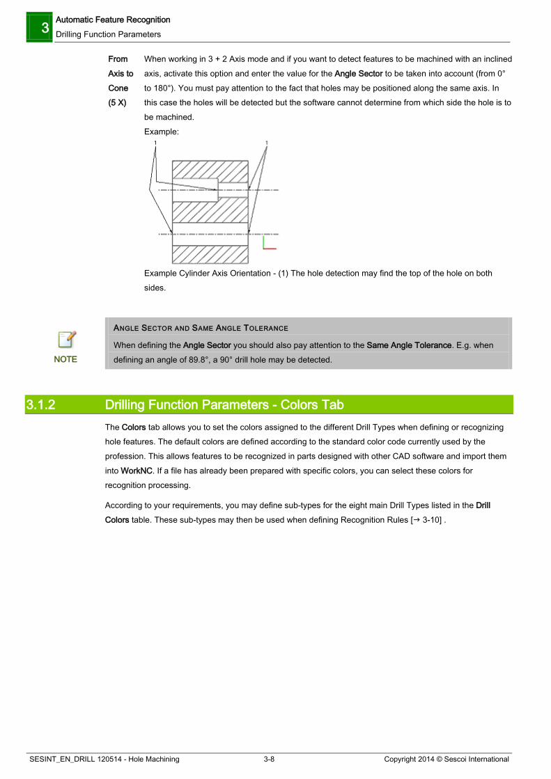
From Axis to Cone (5 X)
When working in 3 + 2 Axis mode and if you want to detect features to be machined with an inclined axis, activate this option and enter the value for the Angle Sector to be taken into account (from 0° to 180°). You must pay attention to the fact that holes may be positioned along the same axis. In this case the holes will be detected but the software cannot determine from which side the hole is to be machined. Example:
Example Cylinder Axis Orientation - (1) The hole detection may find the top of the hole on both sides.
ANGLE SECTOR AND SAME ANGLE TOLERANCE
When defining the Angle Sector you should also pay attention to the Same Angle Tolerance. E.g. when defining an angle of 89.8°, a 90° drill hole may be detected. NOTE
3.1.2 Drilling Function Parameters - Colors Tab The Colors tab allows you to set the colors assigned to the different Drill Types when defining or recognizing hole features. The default colors are defined according to the standard color code currently used by the profession. This allows features to be recognized in parts designed with other CAD software and import them into WorkNC. If a file has already been prepared with specific colors, you can select these colors for recognition processing.
According to your requirements, you may define sub-types for the eight main Drill Types listed in the Drill Colors table. These sub-types may then be used when defining Recognition Rules [ 3-10] .

Automatic Feature Recognition Drilling Function Parameters 3
Copyright 2014 © Sescoi International 3-9 SESINT_EN_DRILL 120514 - Hole Machining
Drilling Function Parameters - Colors Tab
OPTIONS Drill Colors:
This icon allows you to create a new sub-type:
1. Highlight the main drill type to which you want to add a sub-type then click on
the icon on the left side of the dialog box.
2. In the newly created sub-entry line, click on the default sub-type name and rename it with a meaningful name.
3. If required, double click on the color spot to call up the Select Color dialog box and change the sub-type color.
Click on this icon to delete a previously selected sub-type. It is not possible to delete the main types.
Color Spots Double click on the color spots next to each type or sub-type name to call up the Select Color dialog box in order to change the display color of this particular type.
Default Color If you have changed the colors of the main Drill Types, clicking on this button allows you to restore the default colors.
Undefined Click on this color button to call up the Select Color dialog box in order to change the display color of the undefined drilling feature surfaces in the Viewing Area.
(Drilled) Click on this color button to call up the Select Color dialog box in order to define the display color for the drilling features in the Viewing Area to which a drilling strategy has been assigned.
Change the Surface Color according to the Drill Type
Activate this option if you want the surfaces of the drilling features to be displayed with the colors assigned to the Drill Types.
Change the Surface Color on Machined Holes
This option is only available in CAM mode. Activate it if you want the surfaces of the drilling features with associated drilling strategies to be displayed with the color defined for the (Drilled) option.

3 Automatic Feature Recognition Drilling Function Parameters
SESINT_EN_DRILL 120514 - Hole Machining 3-10 Copyright 2014 © Sescoi International
CONTEXT MENU
Depending on the element under the mouse cursor when right clicking in the Drill Type list, a context menu is displayed which may contain the following entries:
Add a new Sub-type Allows you to create a new sub-type.
Delete a Sub-type Allows you to delete a previously selected sub-type.
Rename Allows you to rename a sub-type.
Change the Color Allows you to change the color of a main Drill Type or sub-type.
Expand All Unfolds the tree structure display for all Drill Types. Collapse All Reduces the tree structure display to the main Drill Types.
3.1.3 Drilling Function Parameters - Recognition Options Tab The Recognition Options tab in the Drilling Function Parameters dialog box allows you to set a number of hole recognition parameters and to access the Type Rules Definition dialog box:
Drilling Function Parameters - Recognition Options Tab
DRILL RECOGNITION COMMAND OPTIONS Use Multi-level Recognition
Activate this option to recognize multi-level holes. If this option is not active, recognition is made for the different individual features only without considering stack definitions and the associated strategies from the Rules Definition.
Force If this option is activated, the diameter range/multi-level strategy definition is applied to all holes (including colored holes). In this case, the application will not consider predefined holes from the CAD file and change the colors according to the current Configuration/Rules Definition.
Rules Definition Click on this button to call up the Type Rules Definition dialog box allowing you to define your own rules for complex feature recognition.
Automatic Feature Recognition Drilling Function Parameters 3
Copyright 2014 © Sescoi International 3-11 SESINT_EN_DRILL 120514 - Hole Machining
Automatic Orientation
Activate this option if you want the hole orientation to be determined automatically with respect to neighboring holes. E.g. stacks of multi-level drillings will be oriented in the same direction.
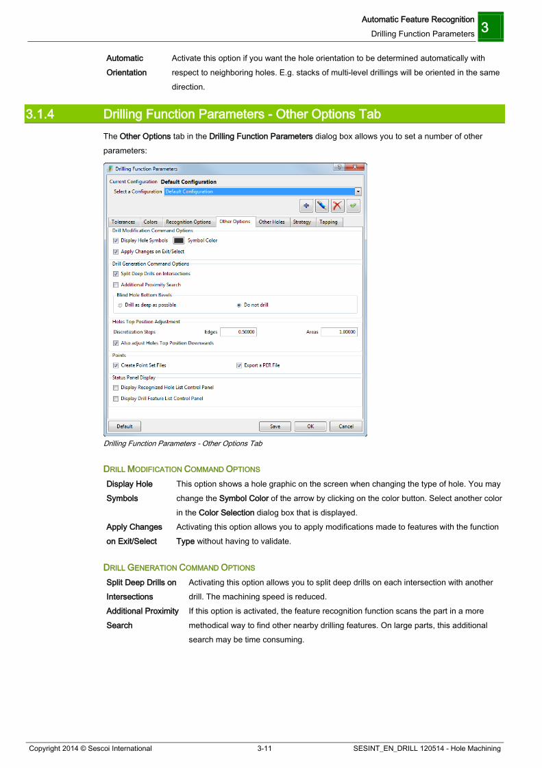
3.1.4 Drilling Function Parameters - Other Options Tab The Other Options tab in the Drilling Function Parameters dialog box allows you to set a number of other parameters:
Drilling Function Parameters - Other Options Tab
DRILL MODIFICATION COMMAND OPTIONS Display Hole Symbols
This option shows a hole graphic on the screen when changing the type of hole. You may change the Symbol Color of the arrow by clicking on the color button. Select another color in the Color Selection dialog box that is displayed.
Apply Changes on Exit/Select
Activating this option allows you to apply modifications made to features with the function Type without having to validate.
DRILL GENERATION COMMAND OPTIONS Split Deep Drills on Intersections
Activating this option allows you to split deep drills on each intersection with another drill. The machining speed is reduced.
Additional Proximity Search
If this option is activated, the feature recognition function scans the part in a more methodical way to find other nearby drilling features. On large parts, this additional search may be time consuming.
3 Automatic Feature Recognition Drilling Function Parameters
SESINT_EN_DRILL 120514 - Hole Machining 3-12 Copyright 2014 © Sescoi International
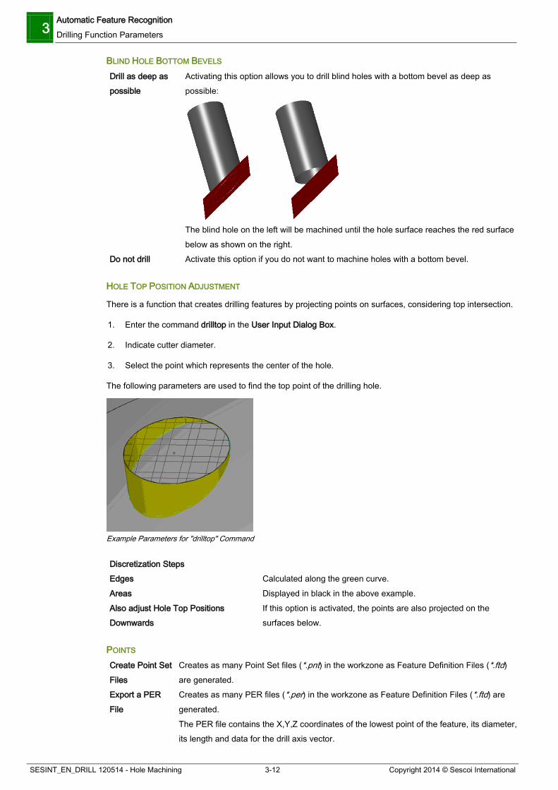
BLIND HOLE BOTTOM BEVELS Drill as deep as possible
Activating this option allows you to drill blind holes with a bottom bevel as deep as possible:
The blind hole on the left will be machined until the hole surface reaches the red surface below as shown on the right.
Do not drill Activate this option if you do not want to machine holes with a bottom bevel.
HOLE TOP POSITION ADJUSTMENT
There is a function that creates drilling features by projecting points on surfaces, considering top intersection.
1. Enter the command drilltop in the User Input Dialog Box.
2. Indicate cutter diameter.
3. Select the point which represents the center of the hole.
The following parameters are used to find the top point of the drilling hole.
Example Parameters for "drilltop" Command
Discretization Steps Edges Calculated along the green curve. Areas Displayed in black in the above example. Also adjust Hole Top Positions Downwards
If this option is activated, the points are also projected on the surfaces below.
POINTS Create Point Set Files
Creates as many Point Set files (*.pnt) in the workzone as Feature Definition Files (*.ftd) are generated.
Export a PER File
Creates as many PER files (*.per) in the workzone as Feature Definition Files (*.ftd) are generated. The PER file contains the X,Y,Z coordinates of the lowest point of the feature, its diameter, its length and data for the drill axis vector.
Automatic Feature Recognition Drilling Function Parameters 3
Copyright 2014 © Sescoi International 3-13 SESINT_EN_DRILL 120514 - Hole Machining
STATUS PANEL DISPLAY Display Recognized Hole List Control Panel
If this option is activated, a dialog box will be displayed after Feature Recognition, listing the recognized holes.
Display Drill Feature List Control Panel
If this option is activated, a dialog box will be displayed when creating the feature definition file to be transferred to WorkNC, allowing you to select the drills to be included in this file.
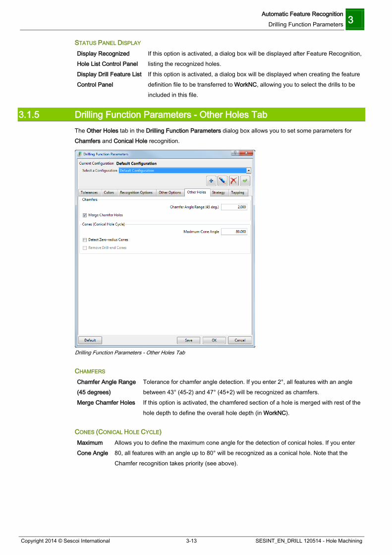
3.1.5 Drilling Function Parameters - Other Holes Tab The Other Holes tab in the Drilling Function Parameters dialog box allows you to set some parameters for Chamfers and Conical Hole recognition.
Drilling Function Parameters - Other Holes Tab
CHAMFERS Chamfer Angle Range (45 degrees)
Tolerance for chamfer angle detection. If you enter 2°, all features with an angle between 43° (45-2) and 47° (45+2) will be recognized as chamfers.
Merge Chamfer Holes If this option is activated, the chamfered section of a hole is merged with rest of the hole depth to define the overall hole depth (in WorkNC).
CONES (CONICAL HOLE CYCLE) Maximum Cone Angle
Allows you to define the maximum cone angle for the detection of conical holes. If you enter 80, all features with an angle up to 80° will be recognized as a conical hole. Note that the Chamfer recognition takes priority (see above).
3 Automatic Feature Recognition Drilling Function Parameters
SESINT_EN_DRILL 120514 - Hole Machining 3-14 Copyright 2014 © Sescoi International
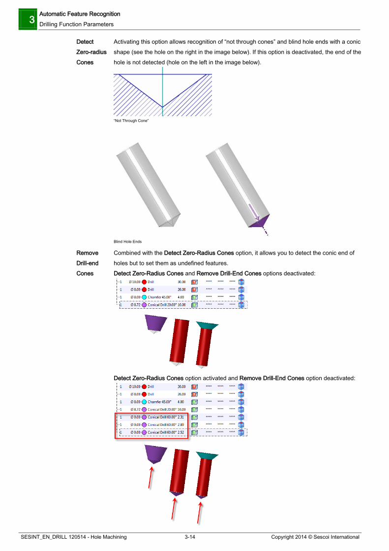
Detect Zero-radius Cones
Activating this option allows recognition of “not through cones” and blind hole ends with a conic shape (see the hole on the right in the image below). If this option is deactivated, the end of the hole is not detected (hole on the left in the image below).
“Not Through Cone”
Blind Hole Ends
Remove Drill-end Cones
Combined with the Detect Zero-Radius Cones option, it allows you to detect the conic end of holes but to set them as undefined features. Detect Zero-Radius Cones and Remove Drill-End Cones options deactivated:
Detect Zero-Radius Cones option activated and Remove Drill-End Cones option deactivated:

Automatic Feature Recognition Drilling Function Parameters 3
Copyright 2014 © Sescoi International 3-15 SESINT_EN_DRILL 120514 - Hole Machining
Detect Zero-Radius Cones and Remove Drill-End Cones options activated:
3.1.6 Drilling Function Parameters - Strategy Tab The Strategy tab in the Drilling Function Parameters dialog box allows you to define the path to the directory for Strategy storage and to define filters for tool search:
Drilling Function Parameters - Strategy Tab
PATH DEFINITION FOR STRATEGIES
The directory for the storage of the user-defined strategies associated with the complex hole definitions depends on the current Configuration. The Pathname field in this dialog box section displays the active directory. Click on the […] button next to the field to call up a browser window allowing you to select or define another location for user-defined drilling strategies.

3 Automatic Feature Recognition Drilling Function Parameters
SESINT_EN_DRILL 120514 - Hole Machining 3-16 Copyright 2014 © Sescoi International
FILTER DEFINITION FOR TOOL SEARCH IN THE TOOL LIBRARY
Clicking on the icon activates the Tool Search Options dialog box allowing you to define filters for tool search in the Tool Library.
Tool Search Options Dialog Box
The upper section of the dialog box indicates the currently active Configuration and the drop-down list allows you to select the Configuration for which you want to define the Tool Search filters.
Two option checkboxes allow you to define whether you want to search only for Tools with a Holder and/or for Tools with a Number.
The list window on the left allows you to select the Operation to which you want to associate tools and indicates the selected Tool Types under the Operation selection drop-down list.
The list window on the right indicates all the available Tool Types. The access path to the Tool Library is indicated in the lower part of the dialog box. If you
want to change it, activate the Tool Library Search Path option and select another pathname in the drop-down list.
To define a Tool Search Filter, proceed as follows:
1. If required, select the Configuration to which you want to apply the Tool Search Options in the drop-down list in the upper section of the dialog box.
2. In the Operations drop-down list, select the hole machining operation which you want to link to certain tools.
3. In the Available Tools list on the right, click on the corresponding tool to highlight it then on the icon between the list windows to add the selected tool type to the Tool Shape list linked to the selected Operation.
4. If required, repeat this step to add other Tool Types which may be used for the hole machining Operation.

Automatic Feature Recognition Drilling Function Parameters 3
Copyright 2014 © Sescoi International 3-17 SESINT_EN_DRILL 120514 - Hole Machining
5. Repeat these steps for other Operations.
6. Click on OK to confirm and to close this dialog box.
To remove a tool from the Operation/Tool Shape list on the left, select the corresponding list
entry and click on the icon between the list windows. To restore the default settings, simply click on the Default button at bottom of the dialog box.
CATEGORY
This section allows you to define the different categories that allow you to sort your manual hole machining strategies. These categories may be used as search criteria for Strategy Selection.
1. Select the category in the corresponding drop-down list.
2. Enter the name of the new category in the corresponding field.
Example of Category Name
By default, 10 categories without a name are available. But you can add categories by clicking on the icon.
DESCRIPTION OF TOOL FAMILIES
This section allows you to define tool families.
1. Click on the icon.
2. Click in the Value column, enter the number that you want to give to the tool family and press [Enter].
3. Click in the Title column, enter the description of the tool family and press [Enter].
Examples of Tool Families
The icon allows you to check and display all the existing tool families in the Tool Library.
You can delete a tool family: select it in the table and click on the icon.
The tool families can then be associated to tools in the Parameter 3 tab of the Tool Library.
You can use them with the Search Tool Filter when defining the Tool Parameters of your Auto User Strategy.
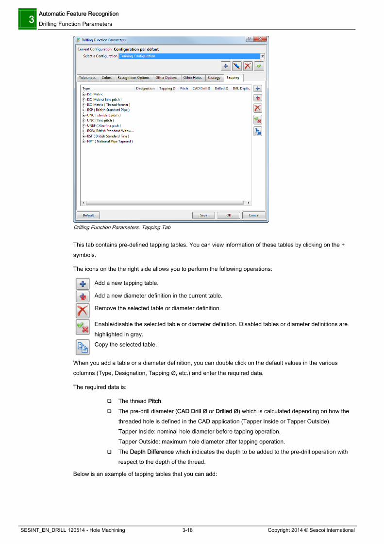
3.1.7 Drilling Function Parameters - Tapping Tab The Tapping tab allows you to define thread data for the tapping feature.
3 Automatic Feature Recognition Drilling Function Parameters
SESINT_EN_DRILL 120514 - Hole Machining 3-18 Copyright 2014 © Sescoi International
Drilling Function Parameters: Tapping Tab
This tab contains pre-defined tapping tables. You can view information of these tables by clicking on the + symbols.
The icons on the the right side allows you to perform the following operations:
Add a new tapping table.
Add a new diameter definition in the current table.
Remove the selected table or diameter definition.
Enable/disable the selected table or diameter definition. Disabled tables or diameter definitions are highlighted in gray.
Copy the selected table.
When you add a table or a diameter definition, you can double click on the default values in the various columns (Type, Designation, Tapping Ø, etc.) and enter the required data.
The required data is:
The thread Pitch. The pre-drill diameter (CAD Drill Ø or Drilled Ø) which is calculated depending on how the
threaded hole is defined in the CAD application (Tapper Inside or Tapper Outside). Tapper Inside: nominal hole diameter before tapping operation. Tapper Outside: maximum hole diameter after tapping operation.
The Depth Difference which indicates the depth to be added to the pre-drill operation with respect to the depth of the thread.
Below is an example of tapping tables that you can add:

Automatic Feature Recognition Moving Recognized Features 3
Copyright 2014 © Sescoi International 3-19 SESINT_EN_DRILL 120514 - Hole Machining
New Tapping Tables
3.2 Moving Recognized Features You can translate recognized features by defining X, Y and Z translation values or according to pre-defined points. You can use this function in the CAD, Preparation and CAM modes.
To illustrate this, we are going to use the hole_drilling_specific.xdw CAD file.
1. Open the CAD file.
2. Create a free point. Enter 0,100,0 in the command input field at the bottom of the user interface.
Point Created on the Part
3. Open the Drilling Manager: click on Transform in the text menu bar, go to the Feature Options menu and select Recognize and Sort Feature.
4. Select a feature in the Viewing Area or the Drilling Manager.
5. Right click on the selected feature in the Viewing Area or the Drilling Manager and select Move Features.

3 Automatic Feature Recognition Moving Recognized Features
SESINT_EN_DRILL 120514 - Hole Machining 3-20 Copyright 2014 © Sescoi International
Context Menu: Move Features
The Move Feature dialog box is displayed:
Move Features Dialog Box
6. Click on the point you have created on the part. Note that if several features are selected, the translation is made with respect to the first selected feature and the selected point. The other features are then translated with the same values.
You should obtain a preview of the translated feature.
7. Click on the Validate button.
You should obtain the following result:

Automatic Feature Recognition Moving Recognized Features 3
Copyright 2014 © Sescoi International 3-21 SESINT_EN_DRILL 120514 - Hole Machining
Translated Feature
Let’s see how to move several features:
1. Select the 4 Tap Drills at the front of the part.
2. Right click on the selection and select Move Features.
3. In the Translation section of the Move Features dialog box, enter -70 in the Y field.
4. Click on the Validate button.
You should obtain the following result:
Translated Features


Automatic Hole Machining Programming your First Hole Machining Toolpath 4
Copyright 2014 © Sescoi International 4-1 SESINT_EN_DRILL 120514 - Hole Machining
4 Automatic Hole Machining
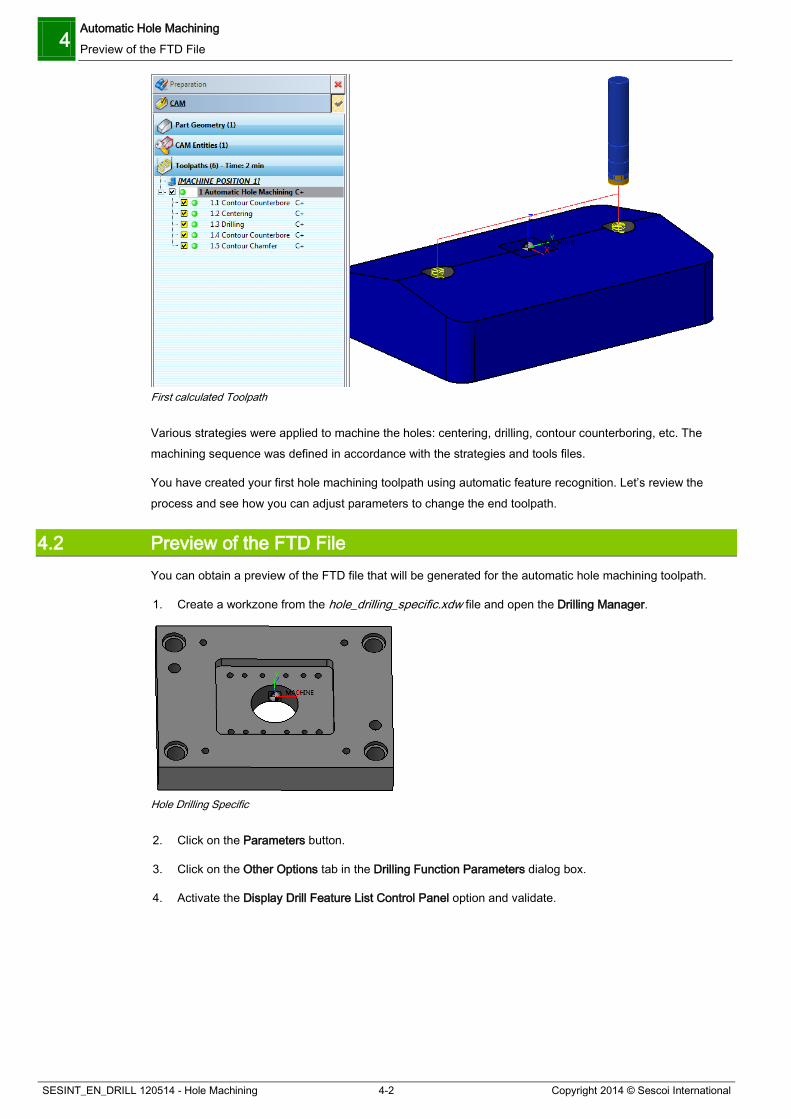
4.1 Programming your First Hole Machining Toolpath To start the training session, we are going to program a first hole machining toolpath using automatic feature recognition and the default tools and strategies files.
1. Open the workzone you have created from the features_01.xdw file.
2. Open the Drilling Manager.
3. Select the four holes in the dialog box and click on the Automatic button. The Automatic Hole Machining toolpath menu is automatically displayed.
First Automatic Hole Machining Toolpath
The Feature Definition drop-down list corresponds to the list of all features to machine. You just have to select the file that contains the machining strategies to be applied and the file that includes all tools available.
4. In the Machine Selection drop-down list, select the simple file.
5. In the Tool Selection drop-down list, select the Default file.
6. Validate the parameters.
7. In the Driling Manager, click on the Close button.
8. Run the toolpath calculations.
You should obtain the following result:
4 Automatic Hole Machining Preview of the FTD File
SESINT_EN_DRILL 120514 - Hole Machining 4-2 Copyright 2014 © Sescoi International
First calculated Toolpath
Various strategies were applied to machine the holes: centering, drilling, contour counterboring, etc. The machining sequence was defined in accordance with the strategies and tools files.
You have created your first hole machining toolpath using automatic feature recognition. Let’s review the process and see how you can adjust parameters to change the end toolpath.
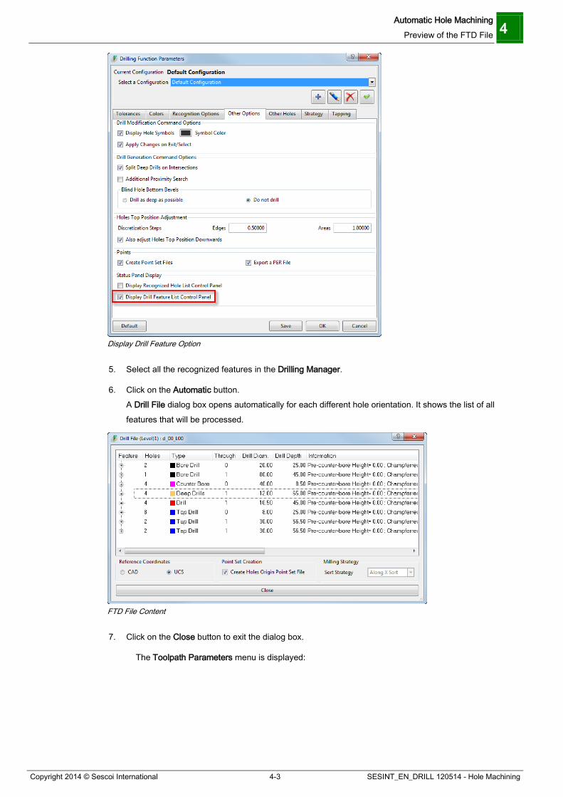
4.2 Preview of the FTD File You can obtain a preview of the FTD file that will be generated for the automatic hole machining toolpath.
1. Create a workzone from the hole_drilling_specific.xdw file and open the Drilling Manager.
Hole Drilling Specific
2. Click on the Parameters button.
3. Click on the Other Options tab in the Drilling Function Parameters dialog box.
4. Activate the Display Drill Feature List Control Panel option and validate.
Automatic Hole Machining Preview of the FTD File 4
Copyright 2014 © Sescoi International 4-3 SESINT_EN_DRILL 120514 - Hole Machining
Display Drill Feature Option
5. Select all the recognized features in the Drilling Manager.
6. Click on the Automatic button. A Drill File dialog box opens automatically for each different hole orientation. It shows the list of all features that will be processed.
FTD File Content
7. Click on the Close button to exit the dialog box.
The Toolpath Parameters menu is displayed:

4 Automatic Hole Machining Preview of the FTD File
SESINT_EN_DRILL 120514 - Hole Machining 4-4 Copyright 2014 © Sescoi International
First Automatic Hole Machining Toolpath
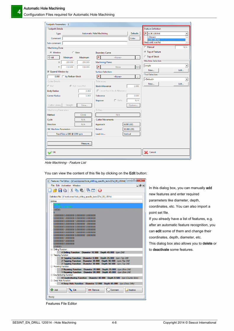
8. Click on the Edit button in the Feature Definition section. The Features File Editor is displayed with the content of the Features Definition file:
Features File Editor

Automatic Hole Machining Configuration Files required for Automatic Hole Machining 4
Copyright 2014 © Sescoi International 4-5 SESINT_EN_DRILL 120514 - Hole Machining
9. Click on the icon to close the Feature File Editor.
10. Validate the parameters.
11. Click on the Close button in the Drilling Manager and run the toolpath calculations.
4.3 Configuration Files required for Automatic Hole Machining There are five configuration files for the Features module which are essential for correct functionality of the Features mode.
These are :
The Features Definition file (*.ftd) This file contains the list and types of holes to be machined (e.g. drilled, bored or tapped holes). This file can be automatically generated using the Automatic Sort function or can be created/modified manually by the user.
The Features Strategy file (*.fts) This file defines the parameters for each operation completed to machine the different types of holes (e.g. a counterbore less than 20mm deep will always be made by milling, whereas a counterbore which is more than 20mm deep will be centered, drilled and finally milled).
The Features Tool file (*.ftt) This file contains the list of tools (e.g. centering drill, drill, tapping tool, etc.) used by the Features module along with their associated parameters.
The Features Option file (*.fto) This file allows two additional parameters to be defined: additional drilling depth for through holes and chamfer parameters.
The Features Construction file (*.ftc) This file defines the method used to machine different types of holes. This file is pre-defined by Vero and must not be edited by users.
The application is delivered with two tool and strategy configuration files called “simple” and "try_to_do_all". They are located under the standard\2dseq folder in WorkNC installation directory. However, you are free to create new files using the menu Utilities > Feature Editor or by clicking on the New button in the Machine Selection section of the Automatic Hole Machining toolpath menu.
4.3.1 Features Definition File (*.ftd) It contains the list of all holes to machine and their machining type (drilling, reaming, tapping, etc.). This file has the .ftd extension and can be found directly in the workzone directory. It is created either automatically after automatic feature recognition or by manually adding features. In all cases, it needs to be selected when you define your Hole Machining toolpath parameters.
4 Automatic Hole Machining Configuration Files required for Automatic Hole Machining
SESINT_EN_DRILL 120514 - Hole Machining 4-6 Copyright 2014 © Sescoi International
Hole Machining - Feature List
You can view the content of this file by clicking on the Edit button:
Features File Editor
In this dialog box, you can manually add new features and enter required parameters like diameter, depth, coordinates, etc. You can also import a point set file. If you already have a list of features, e.g. after an automatic feature recognition, you can edit some of them and change their coordinates, depth, diameter, etc. This dialog box also allows you to delete or to deactivate some features.
Automatic Hole Machining Configuration Files required for Automatic Hole Machining 4
Copyright 2014 © Sescoi International 4-7 SESINT_EN_DRILL 120514 - Hole Machining
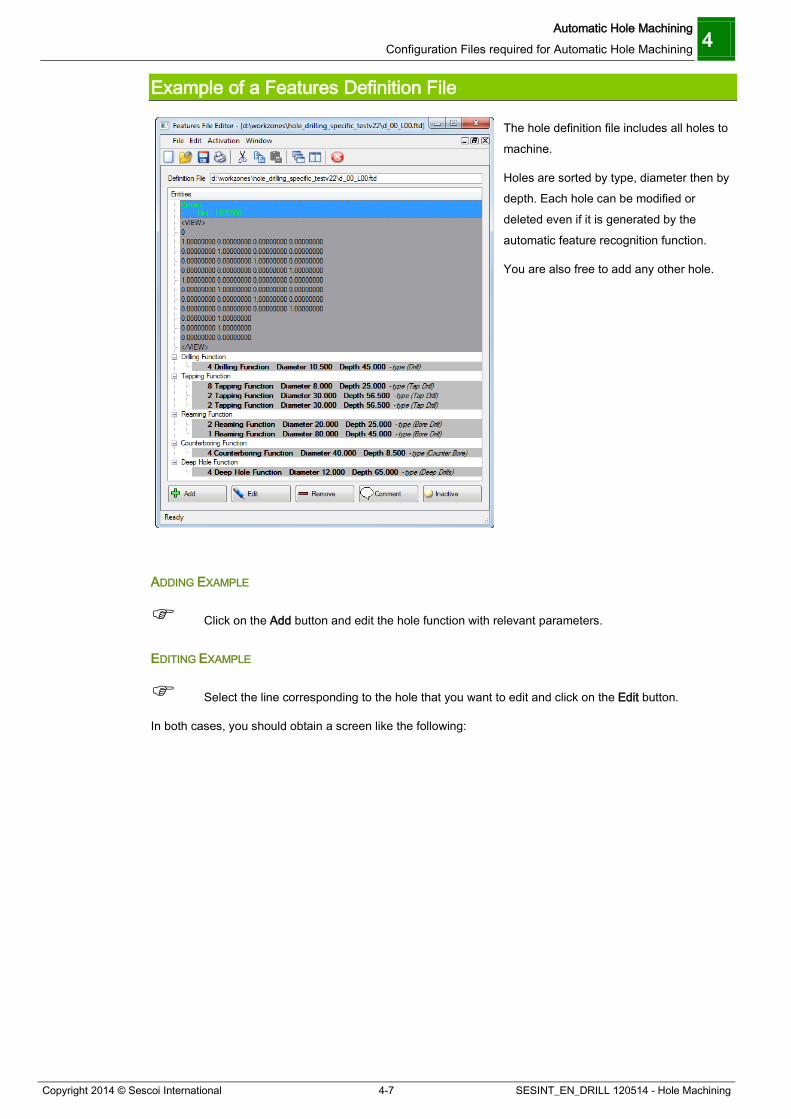
Example of a Features Definition File
The hole definition file includes all holes to machine.
Holes are sorted by type, diameter then by depth. Each hole can be modified or deleted even if it is generated by the automatic feature recognition function.
You are also free to add any other hole.
ADDING EXAMPLE
Click on the Add button and edit the hole function with relevant parameters.
EDITING EXAMPLE
Select the line corresponding to the hole that you want to edit and click on the Edit button.
In both cases, you should obtain a screen like the following:

4 Automatic Hole Machining Configuration Files required for Automatic Hole Machining
SESINT_EN_DRILL 120514 - Hole Machining 4-8 Copyright 2014 © Sescoi International
: Hole type: drilling (hole function), reaming, tapping, etc.
: Diameter and depth of the holes in the list.
: Parameters specific to these holes.
: Coordinates of each hole in the list.
Edit a Definition: Hole Function
Add a new coordinate in the list.
Delete a coordinate from the list.
Import coordinates from an existing list of points.
Export coordinates to a new definition list.
Move coordinates to the top of the list.
Move coordinates to the end of the list.
4.3.2 Strategy Configuration File (*.fts) It allows calling up the right tool you want to use (center drill, drill, reamer, etc.) for a given strategy (centering, drilling, reaming) according to certain rules.
This file corresponds to your machining methods and requires particular attention. You may need a high level of knowledge to customize this file in the best possible way.
Example:
Shallow spot facing (with a depth of less than 20 mm) should be completed with drilling by contouring.
Deep spot facing (with a depth higher than 20 mm) should be completed by pre-drilling, drilling and drilling by contouring
Strategy Configuration File Samples
Automatic Hole Machining Configuration Files required for Automatic Hole Machining 4
Copyright 2014 © Sescoi International 4-9 SESINT_EN_DRILL 120514 - Hole Machining
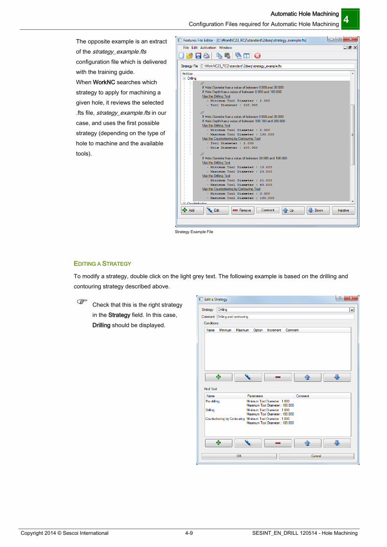
The opposite example is an extract of the strategy_example.fts configuration file which is delivered with the training guide. When WorkNC searches which strategy to apply for machining a given hole, it reviews the selected .fts file, strategy_example.fts in our case, and uses the first possible strategy (depending on the type of hole to machine and the available tools).
Strategy Example File
EDITING A STRATEGY
To modify a strategy, double click on the light grey text. The following example is based on the drilling and contouring strategy described above.
Check that this is the right strategy in the Strategy field. In this case, Drilling should be displayed.

4 Automatic Hole Machining Configuration Files required for Automatic Hole Machining
SESINT_EN_DRILL 120514 - Hole Machining 4-10 Copyright 2014 © Sescoi International
Define the conditions for calling up the tool by
clicking on the icon in the Conditions section. In the present case, there is no specific condition and the tool will be called up in any case.
Finally, enter the tools to be used by clicking
on the icon in the Find Tool section. Note that you may also specify a parameter for the tool such as its diameter: click on the
icon again and enter the required parameter. You may for example specify a minimum and maximum tool diameter for WorkNC to choose the largest and shortest possible tool to complete the operation.
STRATEGY EXAMPLE 1
Strategy Example 1
In this case, we have selected a strategy for the Drilling function.
As you can see ( ), we have defined a condition :
This Drilling function will run only if the Hole diameter is between 30 and 100.
Automatic Hole Machining Configuration Files required for Automatic Hole Machining 4
Copyright 2014 © Sescoi International 4-11 SESINT_EN_DRILL 120514 - Hole Machining
If the drilling respects these strategy conditions, you will machine your drill with :
2 Drilling functions (see ) The first one will take a tool with a diameter between 10 and 20 mm. The second one will take a tool with a diameter between 21 and 40 mm.
Counterboring by Contouring function (see ) This function will take a tool with a diameter between 0 and 100 mm.
Using the *.ftt tool file, the biggest possible diameter will be used to machine the hole.
USE OF THE FIRST POSSIBLE STRATEGY
The first detected strategy will be used to perform an operation if several suitable strategies are defined in the file. NOTE
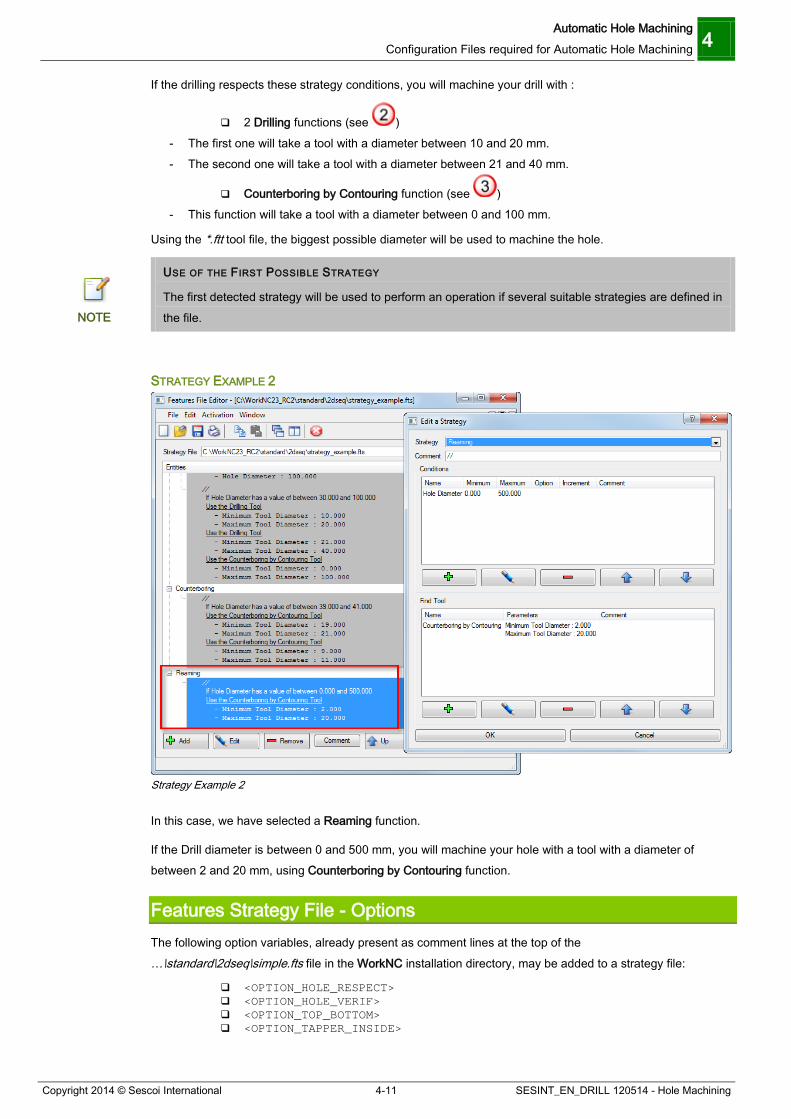
STRATEGY EXAMPLE 2
Strategy Example 2
In this case, we have selected a Reaming function.
If the Drill diameter is between 0 and 500 mm, you will machine your hole with a tool with a diameter of between 2 and 20 mm, using Counterboring by Contouring function.
Features Strategy File - Options The following option variables, already present as comment lines at the top of the …\standard\2dseq\simple.fts file in the WorkNC installation directory, may be added to a strategy file:
<OPTION_HOLE_RESPECT> <OPTION_HOLE_VERIF> <OPTION_TOP_BOTTOM> <OPTION_TAPPER_INSIDE>

4 Automatic Hole Machining Configuration Files required for Automatic Hole Machining
SESINT_EN_DRILL 120514 - Hole Machining 4-12 Copyright 2014 © Sescoi International
(To activate these options in the simple.fts file, double-click on the corresponding comment line and delete the "//" at the beginning of the line.)
<OPTION_HOLE_RESPECT> AND <OPTION_HOLE_VERIF>
If none of the two options is active, the top level of holes having several levels is machined as a counter-bored hole.
As a standard, holes with several levels are considered as flat bottom holes and need not to be defined as Drilling (red) or Counterbore (pink).
Holes with several levels are considered as flat bottom holes
<OPTION_HOLE_RESPECT>
If this option is activated, the user hole type definition is respected. If the user has defined the top level of a hole as drilled hole, it will be drilled and not counter-bored.
COUNTER BORE
If the user wants the top level to be counter-bored, he must necessarily define this hole level as a counter bore. ATTENTION
With <OPTION_HOLE_RESPECT> for hole type Drilling

Automatic Hole Machining Configuration Files required for Automatic Hole Machining 4
Copyright 2014 © Sescoi International 4-13 SESINT_EN_DRILL 120514 - Hole Machining
With <OPTION_HOLE_RESPECT> for hole type Counterbore
<OPTION_HOLE_VERIF>
If this option is active, holes which have the hole type attribute Drilling are checked whether they are flat bottom holes or not. The function compares the bottom of the hole on the upper level and the top of the hole on the lower level. If there is a difference between the two levels, the hole is not considered as being a flat bottom hole and the hole is machined by a drilling operation. Otherwise, the hole machining is made by a counter boring operation.
With <OPTION_HOLE_VERIF> for hole type Drilling
If the hole type of the upper level is defined as Counterbore, hole machining is made by a counter boring operation in all cases.
With <OPTION_HOLE_VERIF> for hole type Counterbore
In the above illustrations, P1 has always the same value.

4 Automatic Hole Machining Configuration Files required for Automatic Hole Machining
SESINT_EN_DRILL 120514 - Hole Machining 4-14 Copyright 2014 © Sescoi International
OPTION DEFINITION
The above options can be defined by adding a Comment in the features strategy file *.fts. It is also possible to add these option variables in the .../config/environ.cfg file: OPTION_HOLE_RESPECT=on OPTION_HOLE_VERIF=on
NOTE
If the <OPTION_HOLE_RESPECT> is active, the <OPTION_HOLE_VERIF> has no effect. ATTENTION
<OPTION_TOP_BOTTOM>
For aligned holes with several levels, there are two possible methods to accomplish the hole machining sequence.
As a standard, the function machines from the smallest to the largest diameter. Example:
Hole Machining from the smallest to the largest diameter
1 Centering 3 Drilling 2 Drilling 4 Counter-boring
The other possibility is to machine from the top of the hole to the bottom. To do so, add <OPTION_TOP_BOTTOM> at the beginning of the feature strategy file.
Example:
Hole Machining from the top to the bottom of the hole
1 Centering 4 Centering 2 Drilling 5 Drilling 3 Counter-boring

Automatic Hole Machining Configuration Files required for Automatic Hole Machining 4
Copyright 2014 © Sescoi International 4-15 SESINT_EN_DRILL 120514 - Hole Machining
<OPTION_TAPPER_INSIDE>
This option variable applies to the Contour Tapping operation for thread milling. It allows using the inner diameter (drilling diameter) of tapper holes, when it has been defined in the CAD system. Some CAD systems indicate the drilling diameter before the Contour Tapping operation.
When this variable is activated, it allows machining the thread depth inside the selected feature.
OPTION_TAPPER_INSIDE = ON OPTION_TAPPER_INSIDE = OFF
4.3.3 Tool Configuration File (*.ftt) It defines the list of your tools (center drill, drill, tap, reamer, etc.) with their relative parameters. Tools are automatically sorted by descending diameter and length.
Tool Parameter Definition All parameters below can be set directly in the Features File Editor. However, you can edit the FTT file manually by using the corresponding parameter code. Example: the Diameter field in the Tool Edition dialog box is actually encoded with “-d” in the FTT file.
Driller
Some parameters apply to certain machining types only (e.g. counterboring, tapping, reaming) and / or to a given hole type only (blind or through hole).

4 Automatic Hole Machining Configuration Files required for Automatic Hole Machining
SESINT_EN_DRILL 120514 - Hole Machining 4-16 Copyright 2014 © Sescoi International
-d Diameter of the tool (see following picture) -l Length of the tool (see following picture)
-to Number of the tool (In the tool carrier on the NC machine) -fc Feed rate -fa Approach rate -fr Rapid rate -s Spindle rotation speed -cy Drill cycle: 1 = direct, 2 = peck, 3=retract (see following picture)
-dz Drill depth f(Cycle) and counterbore (see following picture) -pe Pecking distance (see following picture)
1: Peck 2: Retract -ti Time out f(cycle) (At the end of drilling) -pc (Pre-drilling only): % of centering (Default : 99%): Maximum percentage of hole diameter
for centering -pcm (Pre-drilling only): Max. centering hole diameter: Maximum diameter for centering -dnc Non cutting diameter: Use it to define the pre-drill value where the tool can machine.

Automatic Hole Machining Configuration Files required for Automatic Hole Machining 4
Copyright 2014 © Sescoi International 4-17 SESINT_EN_DRILL 120514 - Hole Machining
-pref Machining preference
0 = Vertical lead-in, constant z-level machining 1 = Ramp lead-in 2 = Vertical lead-in, constant z-level machining (no diameter distinction) 3 = Spiral machining through the whole height: To define how you will lead-in between 2 levels
-dp Pre-drill diameter: Diameter to machine before using the reaming or tapping tool -ddp Stock allowance: stock to leave in the hole before machining with the reaming tool or the
reaming head -p Tapping pitch
-a Tool angle
The tool angle value can also be used to meet special requirements.
If you use a drilling tool that does not need centering, you can configure the tool in such a way that the centering operation will not be required. To obtain such a strategy, you must define an angle value of 0 or less when you define your tool:

4 Automatic Hole Machining Configuration Files required for Automatic Hole Machining
SESINT_EN_DRILL 120514 - Hole Machining 4-18 Copyright 2014 © Sescoi International
Drilling with a flat drilling tool with an angle value of 0° = no centering
Standard drilling tool but with a negative angle value = no centering
If you want to use a flat tool to machine a counterbore, again you must set the angle value to 0 in the tool definition:
If you want to machine a chamfer with the centering tool, you must define your Chamfering by drilling
tool with an angle of -45°.
Centering / Chamfering
Drilling
-pas Lateral stepover (Only for counterboring and conic machining) -dmin Minimum diameter of reaming head (see following picture) -dmax Maximum diameter of reaming head (see following picture)
On a boring head, you can adjust the diameter you want to machine.

Automatic Hole Machining Configuration Files required for Automatic Hole Machining 4
Copyright 2014 © Sescoi International 4-19 SESINT_EN_DRILL 120514 - Hole Machining
Some boring heads examples...
Fine boring heads
Boring range 3-26 mm 25-103,5 mm 99,5 – 269,5 mm 250 – 575 mm 250 – 975 mm
Boring depth 13,5 – 40 mm 3,5 x D 3 x D 400 mm 400 mm
Roughing Finishing
Boring range 25 – 101 mm 99 – 150 mm 25,5 – 103,5 mm 99,5 – 269,5 mm
Boring depth 6 x D 600 mm 6 x D 600 – 700 mm -u1... –u4 Parameters for postprocessor (4): Special optional parameters to be used in the Post
processor. These parameters are only numeric values. -pp (Only when tapping and reaming blind holes) Drill depth, i.e. drilling or tapping distance
added to (or deducted from) the hole depth value when the hole is a blind hole. A positive value is applied to the pre-drill operation while a negative value is applied to the tapping operation. You can enter a negative value for the tapper to be kept at a security distance from the bottom of the hole. The effect of this parameter may be different when a negative or positive maximum tapping depth (-mp) is applied. In any case, the –pp parameter is not taken into account when drilling a through hole.
-pro (Only when reaming and tapping through holes) Through drill depth. This is the pre-drilling and reaming / tapping distance added to the end of the hole. Use with the –ppro parameter The –pro parameter can be combined with the –ppro parameter. Use with the –mp parameter In any case, the –mp parameter (Maximum Tapping Depth, see below) is taken into account.
-ppro (Only when reaming and tapping through holes) Tapping / Reaming distance added to the bottom of the hole. Used in combination with the –pro parameter, it allows you to distinguish the (pre-)drilling and tapping depth. Use with the –mp parameter In any case, the –mp parameter (Maximum Tapping Depth, see below) is taken into account.
-g Approach distance (only for reaming: reamer and reaming head): Distance to stop the reamer or the reaming head, if you do not have through hole from the bottom of the hole
-ty Counterbore type. For example: 0 for roughing tool, 1 for finishing tool. -ch Chamfer width: Chamfer for tapping hole (to be machined before tapping) -cool Coolant code -mp Maximum tapping depth (only applicable if the hole depth is higher)

4 Automatic Hole Machining Configuration Files required for Automatic Hole Machining
SESINT_EN_DRILL 120514 - Hole Machining 4-20 Copyright 2014 © Sescoi International
-hld Holder name -rc Corner radius
Tool Parameters available in Drill Strategies Pre-
drilling Drilling Counter
boring by countouring
Chamfering by drilling
Chamfering by countouring
Reaming Reaming head
Tapping Tool for Conic machining
Type 10 Type 20 Type 40 Type 60 Type 61 Type 70 Type 71 Type 80 Type 90
-d Req Req Req Req Req Req N/A Req Req
-l Req Req Req Req Req Req Req Req Req
-to Req Req Req Req Req Req Req Req Req
-fc Opt Opt Opt Opt Opt Opt Opt Opt Opt
-fa Opt Opt Opt Opt Opt Opt Opt Opt Opt
-fr Opt Opt Opt Opt Opt Opt Opt Opt Opt
-s Opt Opt Opt Opt Opt Opt Opt Opt Opt
-cy Opt Opt Opt Opt Opt Opt Opt Opt Opt -ti N/A Opt Opt Opt Opt Opt Opt Opt Opt
-dz N/A Opt Opt Opt Opt Opt Opt Req Opt
-pe N/A Opt N/A N/A N/A N/A N/A N/A N/A
-pc Req Def=99
%
N/A N/A N/A N/A N/A N/A N/A N/A
-pcm Req Def=5
N/A N/A N/A N/A N/A N/A N/A N/A
-dnc N/A N/A Opt Opt Opt N/A N/A N/A Opt
-pref N/A N/A Opt N/A N/A N/A N/A N/A Opt
-dp N/A N/A N/A N/A N/A Opt Opt Req N/A
-ddp N/A N/A N/A N/A N/A Req Req N/A N/A
-p N/A N/A N/A N/A N/A N/A N/A Req N/A
-a Opt Def=45
Opt Def=45
N/A Opt Def=45
Opt Def=45
N/A N/A N/A Opt Def=0
-pas N/A N/A Req N/A N/A N/A N/A N/A Req
-dmin N/A N/A N/A N/A N/A Opt Req N/A N/A
-dmax N/A N/A N/A N/A N/A Opt Req N/A N/A
-u1… -u4
Opt Opt Opt Opt Opt Opt Opt Opt Opt
-pro N/A N/A N/A N/A N/A Opt Opt Opt N/A
-g N/A N/A N/A N/A N/A Req Req N/A N/A
-pp N/A N/A N/A N/A N/A N/A N/A Req N/A
-ty Opt Opt Opt Opt Opt Opt Opt Opt Opt
-ch N/A N/A N/A N/A N/A N/A N/A Opt N/A
-cool Opt Opt Opt Opt Opt Opt Opt Opt Opt -mp N/A N/A N/A N/A N/A N/A N/A Opt N/A
-hld Opt Opt Opt Opt Opt Opt Opt Opt Opt
-rc N/A N/A N/A N/A N/A N/A N/A N/A Opt
Automatic Hole Machining Configuration Files required for Automatic Hole Machining 4
Copyright 2014 © Sescoi International 4-21 SESINT_EN_DRILL 120514 - Hole Machining
-ppro N/A N/A N/A N/A N/A Opt Opt Opt N/A
LEGEND
N/A: Not applicable
Req: Required
Opt: Optional
Def: Default value
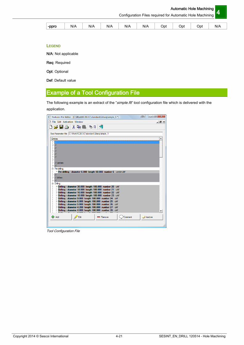
Example of a Tool Configuration File The following example is an extract of the “simple.ftt” tool configuration file which is delivered with the application.
Tool Configuration File
4 Automatic Hole Machining Configuration Files required for Automatic Hole Machining
SESINT_EN_DRILL 120514 - Hole Machining 4-22 Copyright 2014 © Sescoi International
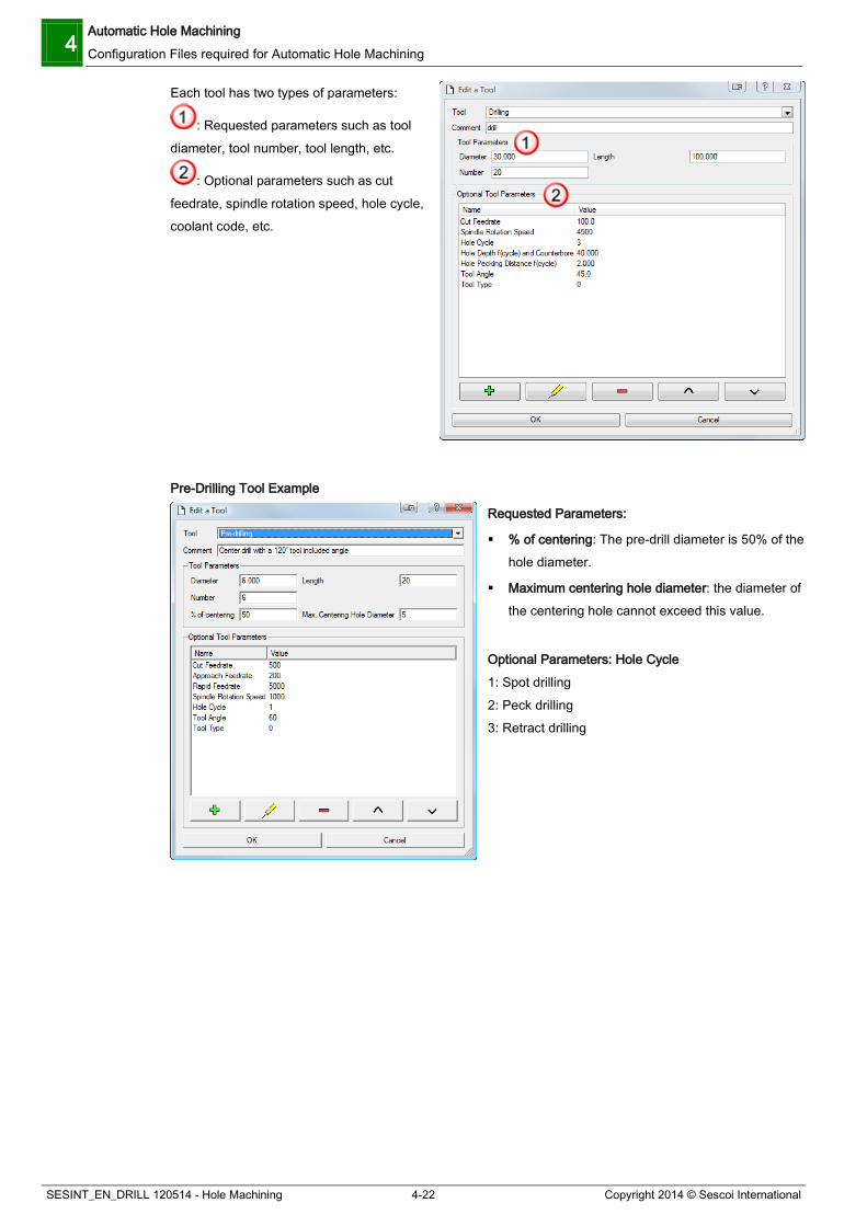
Each tool has two types of parameters:
: Requested parameters such as tool diameter, tool number, tool length, etc.
: Optional parameters such as cut feedrate, spindle rotation speed, hole cycle, coolant code, etc.
Pre-Drilling Tool Example
Requested Parameters:
% of centering: The pre-drill diameter is 50% of the hole diameter.
Maximum centering hole diameter: the diameter of the centering hole cannot exceed this value.
Optional Parameters: Hole Cycle 1: Spot drilling 2: Peck drilling 3: Retract drilling

Automatic Hole Machining Configuration Files required for Automatic Hole Machining 4
Copyright 2014 © Sescoi International 4-23 SESINT_EN_DRILL 120514 - Hole Machining
Drilling Tool Example Optional Parameters: Hole Cycle 1: Spot drilling 2: Peck drilling 3: Retract drilling Hole Pecking Distance: Partial retract distance for chip breaking (2 mm) Time out: Period of time during which the tool remains at the bottom of a hole before retracting Tool Angle: This parameter is automatically set by default to 45°. This parameter represents the tool tip angle. If you define the angle value to “0” or less, you will have the “drilling” operation without centering. Drill depth (cycle) and counterbore: Depth for each drilling tool plunge (Z-step)
Counterboring by Contouring Tool Example
Requested Parameters: Lateral Step: Lateral stepover Optional Parameters:
Hole Depth and Counterbore: Z-step
Machining preference: Lead-in type between two levels: 0 = Vertical lead-in, constant z-level machining 1 = Ramp lead-in 2 = Vertical lead-in, constant z-level machining (no diameter distinction) 3 = Spiral machining through the whole height
Tool type: this value corresponds to the drill tool quality and is linked to the strategy file. 0: Roughing tool 1: Finishing tool Non cutting diameter: Center tool diameter which does not cut
4 Automatic Hole Machining Configuration Files required for Automatic Hole Machining
SESINT_EN_DRILL 120514 - Hole Machining 4-24 Copyright 2014 © Sescoi International
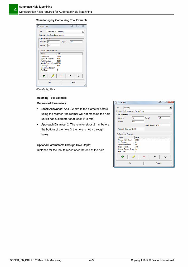
Chamfering by Contouring Tool Example
Chamfering Tool
Reaming Tool Example Requested Parameters:
Stock Allowance: Add 0.2 mm to the diameter before using the reamer (the reamer will not machine the hole until it has a diameter of at least 11.8 mm).
Approach Distance: 2. The reamer stops 2 mm before the bottom of the hole (if the hole is not a through hole).
Optional Parameters: Through Hole Depth: Distance for the tool to reach after the end of the hole

Automatic Hole Machining Configuration Files required for Automatic Hole Machining 4
Copyright 2014 © Sescoi International 4-25 SESINT_EN_DRILL 120514 - Hole Machining
Tapping Tool Example
Warning: Parameters (diameter and length) apply to the thread. Requested Parameters:
Pre-drilling diameter: Diameter to be drilled before tapping: 8.5 mm
Tapping pitch: 1.5
Hole depth (H2): 3. If the hole is not a through hole, this value is added to the tapping depth (H1) for drilling (see H1 and H2 in the drawing below).
Optional Parameters: Through Hole Depth: 5. Extra distance for the tool to tap beyond the bottom of a through hole Chamfer width: 1. Chamfer to be machined before tapping Maximum tapping depth: Allows limiting the tapper going down according to its cutting section. Example: Tapping depth = 20 mm and maximum tapping depth = 15. The tapper will only go down over 15 mm.
Blind Tapping Example
H1: Tapping depth as recognized by WorkNC H2: Drilling depth H2 > 0: The tool will go lower than the tapper (according to the value specified) H2 = 0: The drilling tool and the tapper go down to the same level H2 < 0 :The drilling tool machines down to H1, whereas the tapping tool will stop at the approach distance with respect to the drilling depth
Conical Tool Example
Requested Parameters:
Diameter: Diameter of the bottom part
Lateral step: Lateral stepover
Optional Parameters: Hole Depth: Z-step value Tool Angle: 0 if you want to use a flat tool. For a conical tool, indicate the cone angle value. Non cutting diameter: when using a conical tool, enter the diameter of the non cutting part at the bottom of the tool. Corner Radius: you can use a tool with a corner radius.
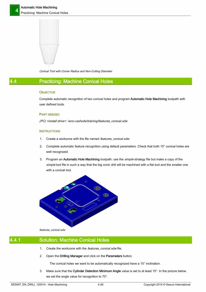
Example of a Conical Tool with Corner Radius and Non Cutting Diameter:
4 Automatic Hole Machining Practicing: Machine Conical Holes
SESINT_EN_DRILL 120514 - Hole Machining 4-26 Copyright 2014 © Sescoi International
Conical Tool with Corner Radius and Non-Cutting Diameter
4.4 Practicing: Machine Conical Holes
OBJECTIVE
Complete automatic recognition of two conical holes and program Automatic Hole Machining toolpath with user defined tools.
PART NEEDED
(PC) <install drive>: \wnc-cad\xdw\training\features_conical.xdw
INSTRUCTIONS
1. Create a workzone with the file named features_conical.xdw.
2. Complete automatic feature recognition using default parameters. Check that both 15° conical holes are well recognized.
3. Program an Automatic Hole Machining toolpath: use the simple strategy file but make a copy of the simple tool file in such a way that the big conic drill will be machined with a flat tool and the smaller one with a conical tool.
features_conical.xdw
4.4.1 Solution: Machine Conical Holes 1. Create the workzone with the features_conical.xdw file.
2. Open the Drilling Manager and click on the Parameters button.
The conical holes we want to be automatically recognized have a 15° inclination.
3. Make sure that the Cylinder Detection Minimum Angle value is set to at least 15°. In the picture below, we set the angle value for recognition to 70°.
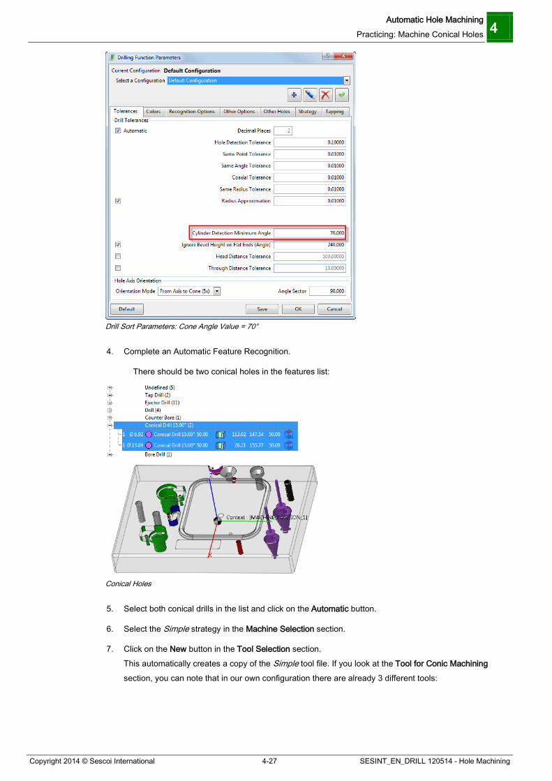
Automatic Hole Machining Practicing: Machine Conical Holes 4
Copyright 2014 © Sescoi International 4-27 SESINT_EN_DRILL 120514 - Hole Machining
Drill Sort Parameters: Cone Angle Value = 70°
4. Complete an Automatic Feature Recognition.
There should be two conical holes in the features list:
Conical Holes
5. Select both conical drills in the list and click on the Automatic button.
6. Select the Simple strategy in the Machine Selection section.
7. Click on the New button in the Tool Selection section. This automatically creates a copy of the Simple tool file. If you look at the Tool for Conic Machining section, you can note that in our own configuration there are already 3 different tools:

4 Automatic Hole Machining Practicing: Machine Conical Holes
SESINT_EN_DRILL 120514 - Hole Machining 4-28 Copyright 2014 © Sescoi International
Default Tools for Conic Machining
8. Click on the Add button and select Tool for Conic Machining in the Tool drop-down list.
9. Add a 12 mm diameter flat tool that will serve to machine the bigger conical drill. The tool parameters should look like the following:
Flat Tool for Conic Machining
Note that we defined a flat tool (0° tool angle) with 1 mm corner radius. The tool is configured to complete 4 mm lateral stepovers and Z steps of 3 mm whenever possible.
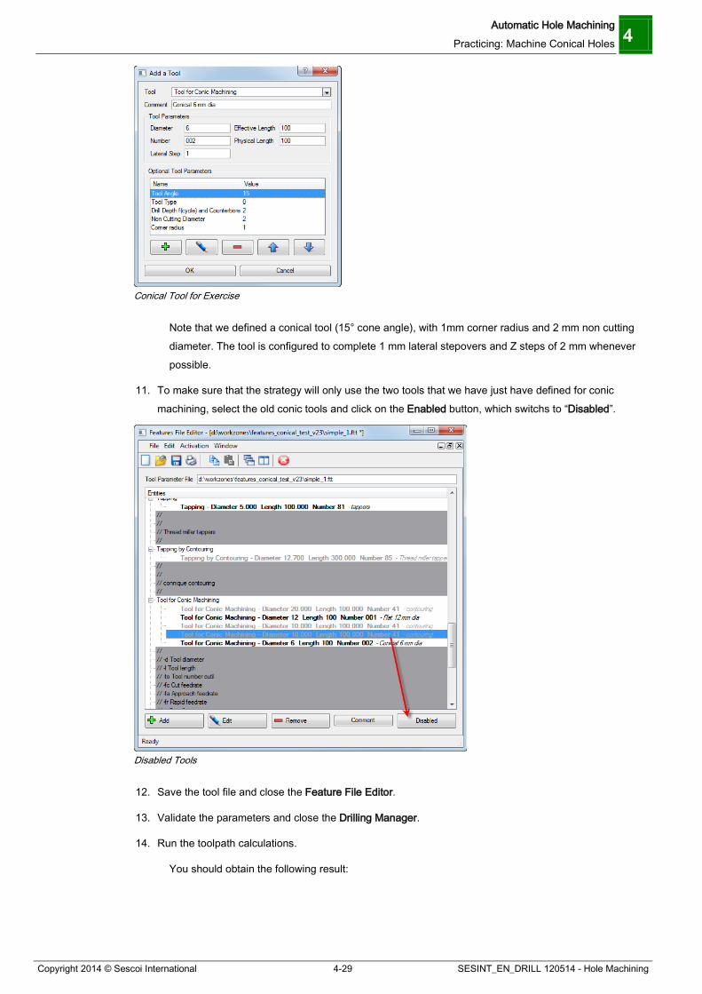
10. Add a 6 mm conical tool that will be used to machine the smaller conic drill. The tool parameters should look like the following:
Automatic Hole Machining Practicing: Machine Conical Holes 4
Copyright 2014 © Sescoi International 4-29 SESINT_EN_DRILL 120514 - Hole Machining
Conical Tool for Exercise
Note that we defined a conical tool (15° cone angle), with 1mm corner radius and 2 mm non cutting diameter. The tool is configured to complete 1 mm lateral stepovers and Z steps of 2 mm whenever possible.
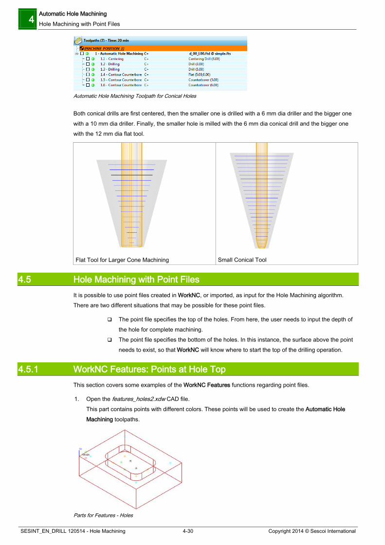
11. To make sure that the strategy will only use the two tools that we have just have defined for conic machining, select the old conic tools and click on the Enabled button, which switchs to “Disabled”.
Disabled Tools
12. Save the tool file and close the Feature File Editor.
13. Validate the parameters and close the Drilling Manager.
14. Run the toolpath calculations.
You should obtain the following result:
4 Automatic Hole Machining Hole Machining with Point Files
SESINT_EN_DRILL 120514 - Hole Machining 4-30 Copyright 2014 © Sescoi International
Automatic Hole Machining Toolpath for Conical Holes
Both conical drills are first centered, then the smaller one is drilled with a 6 mm dia driller and the bigger one with a 10 mm dia driller. Finally, the smaller hole is milled with the 6 mm dia conical drill and the bigger one with the 12 mm dia flat tool.
Flat Tool for Larger Cone Machining
Small Conical Tool
4.5 Hole Machining with Point Files It is possible to use point files created in WorkNC, or imported, as input for the Hole Machining algorithm. There are two different situations that may be possible for these point files.
The point file specifies the top of the holes. From here, the user needs to input the depth of the hole for complete machining.
The point file specifies the bottom of the holes. In this instance, the surface above the point needs to exist, so that WorkNC will know where to start the top of the drilling operation.
4.5.1 WorkNC Features: Points at Hole Top This section covers some examples of the WorkNC Features functions regarding point files.
1. Open the features_holes2.xdw CAD file. This part contains points with different colors. These points will be used to create the Automatic Hole Machining toolpaths.
Parts for Features - Holes

Automatic Hole Machining Hole Machining with Point Files 4
Copyright 2014 © Sescoi International 4-31 SESINT_EN_DRILL 120514 - Hole Machining
2. Create a workzone with this part: click on the New Selection button, press and hold down the [Shift] key, select one of the geometry surfaces and right click to validate. Now, we are going to select all points of the same color so as to create a point set file for each point color in the workzone.
3. Click on the New Selection button again, press and hold down the [Shift] key, click on a blue point: this automatically selects all points of the same color. Right click to validate.
4. Right click on the point set name field and rename it to have a clear description (e.g. ream1_blue_points).
5. Repeat both previous steps for other points of the same color. You should obtain the following result:
Create a Workzone - Point Sets
6. Click on the Create Workzone button.
Once the workzone is created, you can check in the list of entities that all your point set files have been created and imported in the workzone.
Imported Point Sets
We are now going to create an Automatic Hole Machining toolpath and import each individual point set while defining which hole machining function to apply.
1. Create a new toolpath, click on the Type button and select the Automatic Hole Machining toolpath under 2 ½-Axis Toolpaths tab and validate.
2. In the Feature Definition section, click on the Edit button.

4 Automatic Hole Machining Hole Machining with Point Files
SESINT_EN_DRILL 120514 - Hole Machining 4-32 Copyright 2014 © Sescoi International
Feature File Editor
3. Click on the Add button to add a new hole machining function.
4. In the Definition drop-down list, select the Reaming Function: use a Diameter of 50 and a Depth of 150.
Add a Definition
We are now going to import the file which includes the points for reaming.
5. Click on the icon, and double click on the ream1_blue_points.pnt file. All points in the file have been imported in the Add a Definition dialog box:

Automatic Hole Machining Hole Machining with Point Files 4
Copyright 2014 © Sescoi International 4-33 SESINT_EN_DRILL 120514 - Hole Machining
Imported Points
6. Click OK to validate.
Features File Editor - Reaming Function
7. Click on the Add button to add a new hole machining function. This time, select the Tapping Function and use a Diameter of 16 and a Depth of 100.
8. Click on the icon and double click on the tap1_orange_points.pnt file.
9. Click OK to validate.
10. Click on the Add button to add a new hole machining function. This time, select the Drilling function and use a Diameter of 10 and a Depth of 100.
11. Click on the icon and double click on the drill1_black_points.pnt file.
12. Click OK to validate.
13. Click on the Add button to add a new hole machining function. This time, select the Counterbored Hole Function and use a Diameter D1 of 10 and a Depth of 80, a Diameter D2 of 20 and a Depth 20.
14. Click on the icon and double click on the bore1_green_points.pnt file.
15. Click OK to validate.
You should obtain the following result:

4 Automatic Hole Machining Hole Machining with Point Files
SESINT_EN_DRILL 120514 - Hole Machining 4-34 Copyright 2014 © Sescoi International
Features File Editor - All Functions
16. Save your file, name the file drillpts and close the Features File Editor.
17. Select the drillpts.ftd file that we just saved in the Feature Definition section.
18. Select try_to_do_all in the Machine Selection section.
19. Select default in the Tool Selection section.
Automatic Hole Machining – Parameters Defined
20. Validate the parameters and run the toolpath calculations
You should obtain the following result:

Automatic Hole Machining Hole Machining with Point Files 4
Copyright 2014 © Sescoi International 4-35 SESINT_EN_DRILL 120514 - Hole Machining
Automatic Hole Machining: Sub-Toolpaths
4.5.2 WorkNC Features: Points at bottom of Holes This section covers some examples of the WorkNC Features functions regarding point files, where the point is at the bottom of the hole.
1. Open the features_holes3.xdw CAD file. The points will be used to create the Automatic Hole Machining toolpaths, where the points will be at the bottom of holes. Note that for calculation of the correct starting depths, surface data must exist above the holes.
Part with Bottom Holes
2. Create a workzone: click New Selection and press the [Ctrl]+[A] keys and right click to validate. You have selected a set of surfaces and a set of points.
Selection of Surfaces and Points

4 Automatic Hole Machining Hole Machining with Point Files
SESINT_EN_DRILL 120514 - Hole Machining 4-36 Copyright 2014 © Sescoi International
3. Click on the Create Workzone button.
4. Rename the point set into ejector_holes in the Workzone Manager.
5. Create an Automatic Hole Machining toolpath.
6. Click the Edit button under Feature Definition section.
The Features File Editor is displayed.
7. Click on the Add button to add a new hole machining function.
8. Select the Drilling Function in the Definition drop-down list and enter the following parameters: Use a Diameter of 4 and a Depth of –1. Note that the value -1 indicates to WorkNC that the point is the bottom of the hole, and triggers WorkNC to calculate it as such.
9. Click on the icon to select the point set that was activated in the workzone, i.e. ejector_holes.pnt.
Add a Definition: Hole Function
10. Click OK to validate.
Features File Editor - Hole Function
11. Save your file as drillpts.
12. Close the Features File Editor.
13. Select the drillpts.ftd file that we just saved in the Feature Definition section.
14. Select try_to_do_all in the Machine Selection section.
15. Select default in the Tool Selection section.

Automatic Hole Machining Create Automatic Hole Machining Toolpath from a 2D File 4
Copyright 2014 © Sescoi International 4-37 SESINT_EN_DRILL 120514 - Hole Machining
Toolpath Parameters - Bottom Holes
16. Validate the parameters and run the toolpath calculations.
You should obtain the following result:
Toolpath - Bottom Holes
In this example, it uses the points as the bottoms of the holes.
4.6 Create Automatic Hole Machining Toolpath from a 2D File WorkNC allows you to define drilling features from a 2D geometry file such as a DXF file. For this, you should first create a workzone from your 2D file.
Open the 2D_boring.dxf file.
2D_Boring_Dxf_File

4 Automatic Hole Machining Create Automatic Hole Machining Toolpath from a 2D File
SESINT_EN_DRILL 120514 - Hole Machining 4-38 Copyright 2014 © Sescoi International
Click on the icon and select the Curve machining type.
Create a Workzone - Curve Machining
Click on the New Selection button and click the four edges of the drawing.
Selected Edges
Right click to confirm your selection.
Save your file in the XDW format.
Activate the Include Unselected Entities option. This will automatically export all entities within the four edges into the newly created workzone, including the circles that we want to use for boring.

Automatic Hole Machining Create Automatic Hole Machining Toolpath from a 2D File 4
Copyright 2014 © Sescoi International 4-39 SESINT_EN_DRILL 120514 - Hole Machining
Include Unselected Entities
Click on the Create Workzone button.
When loading the created workzone, you can only see the four edges.
Activate the Preparation mode and show all layers:
Show Layers in Preparation Mode
We can now select the circles on the 2D geometry to create drilling types. For this, we need to activate the Features from Circles toolbar.
Right click at the end of the horizontal toolbars in the upper part of the user interface and activate the Features from Circles toolbar.
4 Automatic Hole Machining Create Automatic Hole Machining Toolpath from a 2D File
SESINT_EN_DRILL 120514 - Hole Machining 4-40 Copyright 2014 © Sescoi International
Features from Circles
You should now have an additional expandable toolbar. In our example, we moved it below the vertical toolbars on the left.
Press and hold down the left mouse button on the icon to expand the toolbar and see available options.
As you can see, there is one icon for each feature type (boring, drilling, tapping and counterboring).
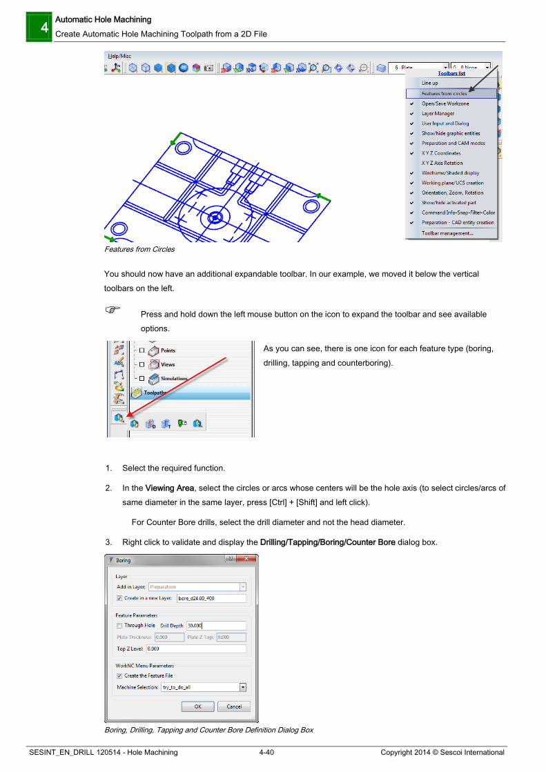
1. Select the required function.
2. In the Viewing Area, select the circles or arcs whose centers will be the hole axis (to select circles/arcs of same diameter in the same layer, press [Ctrl] + [Shift] and left click).
For Counter Bore drills, select the drill diameter and not the head diameter.
3. Right click to validate and display the Drilling/Tapping/Boring/Counter Bore dialog box.
Boring, Drilling, Tapping and Counter Bore Definition Dialog Box

Automatic Hole Machining Create Automatic Hole Machining Toolpath from a 2D File 4
Copyright 2014 © Sescoi International 4-41 SESINT_EN_DRILL 120514 - Hole Machining
4. Select whether you want to add the selected entities to the current layer. You may also add them to a newly created layer. The name of this layer indicates the feature type, the hole diameter and a number. You can rename it as required.
5. Set the Feature Parameters.
- Enter the Drill Depth.
- If you want to drill a Through Hole, activate the corresponding option and define the Plate Thickness and the Plate Z top.
6. Enter the Top Z Level of the drill.
7. Click on OK.
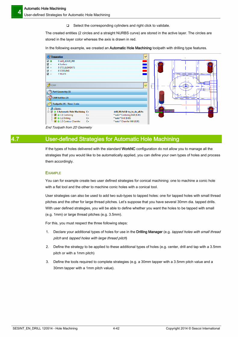
The application automatically creates the cylindrical surfaces for the selected features. - Drilling features are created in red color. - Tapping features are created in blue color. - Boring features are created in black color. - Counter bore features are created in pink and red color.
You can then use the Drilling Manager to automatically recognize the created features.
If you want to create the corresponding Feature Definition File and display the Hole Machining toolpath menu immediately, activate the option Create the Feature File in the WorkNC Menu Parameters section of this dialog box and select the machine definition to be used in the Machine Selection list.
COUNTER BORE PARAMETERS
The parameters that WorkNC uses to create Counter Bores are defined in the drill_feature.ini file which is to be found in the $WNCHOME\client\users\username\ directory.
The [DRILL_FEATURES] section contains a list of pre-defined values, where the first value represents the screw hole diameter, the second one the head diameter and the third one the counter bore depth. These values are separated by semicolons. The following default values are defined:
1= 3.0 ; 6.0 ; 3.2 2= 4.0 ; 8.0 ; 4.5 3= 5.0 ; 9.0 ; 5.5 4= 6.0 ; 10.0 ; 6.5 5= 8.0 ; 12.0 ; 8.5 6= 10.0 ; 14.0 ; 11.0 7= 12.0 ; 16.0 ; 13.0 8= 14.0 ; 18.0 ; 15.0 9= 16.0 ; 20.0 ; 17.0 10= 18.0 ; 24.0 ; 18.0 11= 20.0 ; 30.0 ; 21.0
Example: If the circle diameter is 6.2, WorkNC will draw a screw hole with a diameter of 6.2, a head diameter of 10.0 with a depth of 6.5.
FIND BASE ENTITIES OF CYLINDERS
The Find Base Entities of Cylinders function allows you to extract the cylinder extremity curves and to draw the whole cylinder axis even if the cylinder surfaces have been trimmed before.
4 Automatic Hole Machining User-defined Strategies for Automatic Hole Machining
SESINT_EN_DRILL 120514 - Hole Machining 4-42 Copyright 2014 © Sescoi International
Select the corresponding cylinders and right click to validate.
The created entities (2 circles and a straight NURBS curve) are stored in the active layer. The circles are stored in the layer color whereas the axis is drawn in red.
In the following example, we created an Automatic Hole Machining toolpath with drilling type features.
End Toolpath from 2D Geometry
4.7 User-defined Strategies for Automatic Hole Machining If the types of holes delivered with the standard WorkNC configuration do not allow you to manage all the strategies that you would like to be automatically applied, you can define your own types of holes and process them accordingly.
EXAMPLE
You can for example create two user defined strategies for conical machining: one to machine a conic hole with a flat tool and the other to machine conic holes with a conical tool.
User strategies can also be used to add two sub-types to tapped holes: one for tapped holes with small thread pitches and the other for large thread pitches. Let’s suppose that you have several 30mm dia. tapped drills. With user defined strategies, you will be able to define whether you want the holes to be tapped with small (e.g. 1mm) or large thread pitches (e.g. 3.5mm).
For this, you must respect the three following steps:
1. Declare your additional types of holes for use in the Drilling Manager (e.g. tapped holes with small thread pitch and tapped holes with large thread pitch)
2. Define the strategy to be applied to these additional types of holes (e.g. center, drill and tap with a 3.5mm pitch or with a 1mm pitch)
3. Define the tools required to complete strategies (e.g. a 30mm tapper with a 3.5mm pitch value and a 30mm tapper with a 1mm pitch value).

Automatic Hole Machining User-defined Strategies for Automatic Hole Machining 4
Copyright 2014 © Sescoi International 4-43 SESINT_EN_DRILL 120514 - Hole Machining
SUMMARY OF USER-DEFINED STRATEGIES
User-defined Strategies
4.7.1 Declaring additional Types of Holes To declare additional types of holes for use in the Drilling Manager, you have to edit the file drill_specificstrategies.ini which is stored under your own user directory in the WorkNC installation directory.
For example:
C:\WorkNC\Client\Users\psmith
Open the drill_specificstrategies.ini file with a text editor. If you have never edited the file, it may be empty.
Add the hole type on which your own type will be based. For the file to be read correctly by WorkNC, each basic hole type should be introduced with the relevant column header, as shown below.
Drill specific strategies
For practical reasons, we recommend that you add all possible types in the file at the same time.

4 Automatic Hole Machining User-defined Strategies for Automatic Hole Machining
SESINT_EN_DRILL 120514 - Hole Machining 4-44 Copyright 2014 © Sescoi International
In our example, we want to add specific strategies for tapped drills. Thus you have to type the following under the relevant section header.
USS1 =10, #ff5500, Tapped with small thread
The line syntax must respect the following rules.
USS1 USS must be left as is and complemented with a number from 1 to 99. The number has no real importance and is used to differentiate each specific strategy you are going to create. You can have USS1, USS2, USS3, etc.
= 10 The number you attach to the strategy after the = symbol is very important since it is the one that you will use for reference in the strategy file (fts file). You can choose any number from 1 to 99.
#ff5500 The code after the # symbol corresponds to the color code that will be used to represent the specific drill type in the Drilling Manager. You can choose any color.
Tapped with small thread
The text you enter here will be displayed when defining hole types in the Drilling Manager.
Since we want to add two different strategies depending on whether you want to tap a small or large thread pitch, we added a second strategy line. Our drill_specificstrategies.ini file now looks like the following:
drill_specificstrategies_ini File
Save and close the file.
You can now check that both additional drill types are available in the Drilling Manager.
Start or restart the WorkNC application.
Create a workzone with the hole_drilling_specific.xdw file.
Show a top view of the part. We are now going to change the type of the 30mm dia bore drills into specific tap drills. Both holes at the top will be machined as tapped drills with a small thread pitch while the two others will be machined as tapped drills too but with a large thread pitch.
Activate the Drilling Manager.
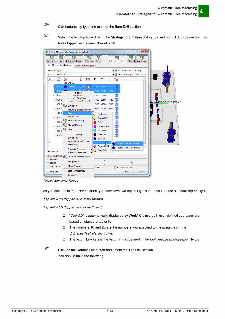
Automatic Hole Machining User-defined Strategies for Automatic Hole Machining 4
Copyright 2014 © Sescoi International 4-45 SESINT_EN_DRILL 120514 - Hole Machining
Sort features by type und expand the Bore Drill section.
Select the two top bore drills in the Strategy Information dialog box and right click to define them as holes tapped with a small thread pitch.
Tapped with small Thread
As you can see in the above picture, you now have two tap drill types in addition to the standard tap drill type:
Tap drill – 10 (tapped with small thread)
Tap drill – 20 (tapped with large thread)
“Tap drill” is automatically displayed by WorkNC since both user-defined sub-types are based on standard tap drills.
The numbers 10 and 20 are the numbers you attached to the strategies in the drill_specificstrategies.ini file.
The text in brackets is the text that you defined in the drill_specificstrategies.ini file too.
Click on the Rebuild List button and unfold the Tap Drill section. You should have the following:

4 Automatic Hole Machining User-defined Strategies for Automatic Hole Machining
SESINT_EN_DRILL 120514 - Hole Machining 4-46 Copyright 2014 © Sescoi International
User-defined Tapped Drills
We have to define the strategies and tools that we want to apply to process such hole types.
4.7.2 Creating a User-defined Strategy To create the strategies matching our user-defined tap drill types, we are going to use the Simple strategy as the basis.
Create an Automatic Hole Machining toolpath with the four user-defined tapped drills.
Create an Automatic Hole Machining Toolpath
Select the Simple strategy in the Machine Selection field and click on the New button.
Attach a name to the the strategy file that you want to create.

Automatic Hole Machining User-defined Strategies for Automatic Hole Machining 4
Copyright 2014 © Sescoi International 4-47 SESINT_EN_DRILL 120514 - Hole Machining
New Machine Name
Click OK. The Features File Editor opens automatically.
Features File Editor: Simple Specific Tap
Click on the Add button.
Select the Tapping strategy type.
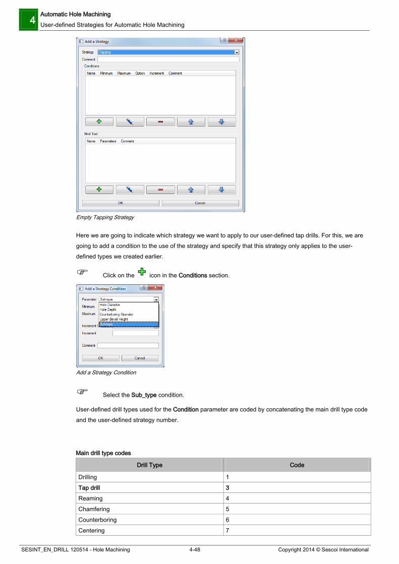
4 Automatic Hole Machining User-defined Strategies for Automatic Hole Machining
SESINT_EN_DRILL 120514 - Hole Machining 4-48 Copyright 2014 © Sescoi International
Empty Tapping Strategy
Here we are going to indicate which strategy we want to apply to our user-defined tap drills. For this, we are going to add a condition to the use of the strategy and specify that this strategy only applies to the user-defined types we created earlier.
Click on the icon in the Conditions section.
Add a Strategy Condition
Select the Sub_type condition.
User-defined drill types used for the Condition parameter are coded by concatenating the main drill type code and the user-defined strategy number.
Main drill type codes
Drill Type Code
Drilling 1
Tap drill 3 Reaming 4
Chamfering 5
Counterboring 6
Centering 7

Automatic Hole Machining User-defined Strategies for Automatic Hole Machining 4
Copyright 2014 © Sescoi International 4-49 SESINT_EN_DRILL 120514 - Hole Machining
Drill Type Code
Conic 10 Ejector 13
If you remember, when adding the user-defined strategies in the drill_specificstrategies.ini file, we attached # 10 to the tapping strategy with a small thread pitch and # 20 to the strategy with a large thread pitch. This means that the code for use of the tapping strategy with a small thread is 310 (3 and 10). That of the strategy with a large thread is 320 (3 and 20).
So enter the 310 code in both Minimum and Maximum fields.
310 Strategy Code
Click OK.
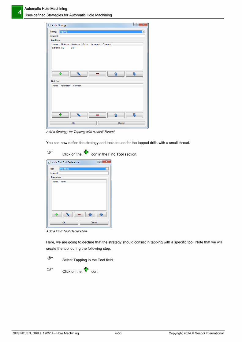
4 Automatic Hole Machining User-defined Strategies for Automatic Hole Machining
SESINT_EN_DRILL 120514 - Hole Machining 4-50 Copyright 2014 © Sescoi International
Add a Strategy for Tapping with a small Thread
You can now define the strategy and tools to use for the tapped drills with a small thread.
Click on the icon in the Find Tool section.
Add a Find Tool Declaration
Here, we are going to declare that the strategy should consist in tapping with a specific tool. Note that we will create the tool during the following step.
Select Tapping in the Tool field.
Click on the icon.

Automatic Hole Machining User-defined Strategies for Automatic Hole Machining 4
Copyright 2014 © Sescoi International 4-51 SESINT_EN_DRILL 120514 - Hole Machining
Add a Find Tool Parameter - Tool Type
Select the Tool Type option.
Enter a tool type number in the Value field.
The tool type number can have any value but the same value must be used in the Tool file (ftt file). Here, we chose number 10. This means that the strategy will use the tool with 10 as tool type number. The strategy will only use this tool. If no tool is found with the tool type number, the strategy will not be applied.
Tapping Tool Type # 10
Click OK.
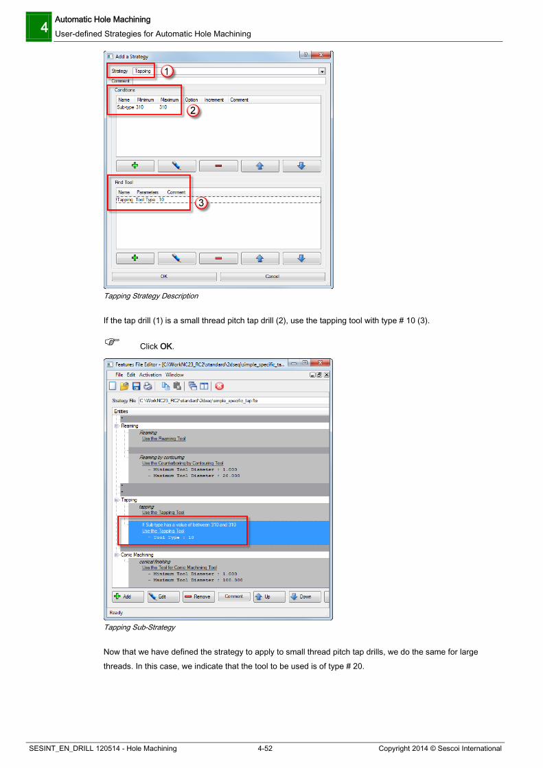
4 Automatic Hole Machining User-defined Strategies for Automatic Hole Machining
SESINT_EN_DRILL 120514 - Hole Machining 4-52 Copyright 2014 © Sescoi International
Tapping Strategy Description
If the tap drill (1) is a small thread pitch tap drill (2), use the tapping tool with type # 10 (3).
Click OK.
Tapping Sub-Strategy
Now that we have defined the strategy to apply to small thread pitch tap drills, we do the same for large threads. In this case, we indicate that the tool to be used is of type # 20.

Automatic Hole Machining User-defined Strategies for Automatic Hole Machining 4
Copyright 2014 © Sescoi International 4-53 SESINT_EN_DRILL 120514 - Hole Machining
Tapping Sub-Strategy (Tool type 20)
The sequence order of the strategies is also very important. If we leave the strategy file as is in the above picture, we will not obtain the expected result: the first strategy in the list (Tapping – Use the tapping tool) will be used in all cases since it has no condition. We must change the sequence order for specific strategies to be applied first.
Highlight the first tapping strategy and click on the Down icon for it to appear below the specific strategies as in the picture below.
Strategy Sequence Order

4 Automatic Hole Machining User-defined Strategies for Automatic Hole Machining
SESINT_EN_DRILL 120514 - Hole Machining 4-54 Copyright 2014 © Sescoi International
Save and close the strategy file.
We must now define the tappers that may be used.
4.7.3 Creating Tools for Sub-strategies The tools for use in user-defined strategies are referred to through their tool type number. In our example, we defined that tapping with a small thread pitch requires the use of a tool of type # 10, while large thread pitch tapping requires the use of tools of type # 20.
Select your *.ftt file.
Click on the Edit button in the Tool Selection field. A tool file based on the simple tool file is automatically created and named in accordance with the name of the strategy file (simple_specific_tap.ftt in our example).
Tappers in simple_specific_tap.ftt File
We are now going to add tools to match user-defined strategies.
Let’s start with the small thread pitch tapper…
Click on the Add button.
Select Tapping in the first field.
Define the tool parameters.
In our example, the tap drills we would like to mill have a 30mm diameter. Since we are adding the small thread pitch tapper, we enter a 1mm tapping pitch.
For the link to be made correctly, we must specify that the tool we are editing is a tool of type 10.
Since the Tool Type parameter already appears in the list of optional parameters, click in the Value field, enter 10 and press [Enter].

Automatic Hole Machining User-defined Strategies for Automatic Hole Machining 4
Copyright 2014 © Sescoi International 4-55 SESINT_EN_DRILL 120514 - Hole Machining
Tool Type # 10
Remember the number we attached to the tool (Number 1) since it will allow us to check which tool is actually used in our toolpath.
Click OK.
Repeat the same procedure to add the tapper used to mill with a larger thread pitch. This tapper has a 3.5mm pitch value, is of type 20 and was given 2 as number.
Save and close the tool file, then leave the Features File Editor.
You can now start the calculation of the Hole Machining toolpath.
4.7.4 Checking the Use of Sub-Strategies Once you have run the toolpath calculations, you should obtain the following:
Sub-Strategies
As you can see, two different tappers were used to mill the 30mm tap drills. If you show the parameters of the toolpath # 1.4 and click on the Tapper button to show the tool that was used, you should note that it is the tool # 1 (small thread tapper).

4 Automatic Hole Machining User-defined Strategies for Automatic Hole Machining
SESINT_EN_DRILL 120514 - Hole Machining 4-56 Copyright 2014 © Sescoi International
Tool Number 1
If you do the same for the toolpath # 1.5, you should obtain the following:
Tool Number 2
The tapper # 2 was used in this case.
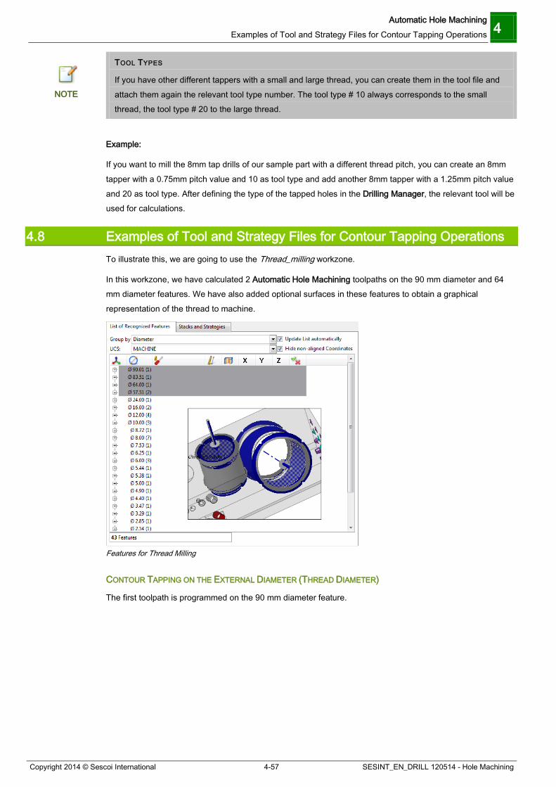
Automatic Hole Machining Examples of Tool and Strategy Files for Contour Tapping Operations 4
Copyright 2014 © Sescoi International 4-57 SESINT_EN_DRILL 120514 - Hole Machining
TOOL TYPES
If you have other different tappers with a small and large thread, you can create them in the tool file and attach them again the relevant tool type number. The tool type # 10 always corresponds to the small thread, the tool type # 20 to the large thread.
NOTE
Example:
If you want to mill the 8mm tap drills of our sample part with a different thread pitch, you can create an 8mm tapper with a 0.75mm pitch value and 10 as tool type and add another 8mm tapper with a 1.25mm pitch value and 20 as tool type. After defining the type of the tapped holes in the Drilling Manager, the relevant tool will be used for calculations.
4.8 Examples of Tool and Strategy Files for Contour Tapping Operations To illustrate this, we are going to use the Thread_milling workzone.
In this workzone, we have calculated 2 Automatic Hole Machining toolpaths on the 90 mm diameter and 64 mm diameter features. We have also added optional surfaces in these features to obtain a graphical representation of the thread to machine.
Features for Thread Milling
CONTOUR TAPPING ON THE EXTERNAL DIAMETER (THREAD DIAMETER)
The first toolpath is programmed on the 90 mm diameter feature.
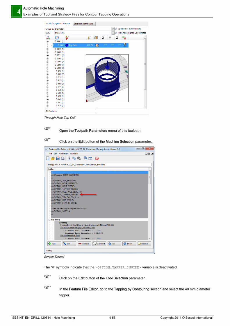
4 Automatic Hole Machining Examples of Tool and Strategy Files for Contour Tapping Operations
SESINT_EN_DRILL 120514 - Hole Machining 4-58 Copyright 2014 © Sescoi International
Through Hole Tap Drill
Open the Toolpath Parameters menu of this toolpath.
Click on the Edit button of the Machine Selection parameter.
Simple Thread
The “//” symbols indicate that the <OPTION_TAPPER_INSIDE> variable is deactivated.
Click on the Edit button of the Tool Selection parameter.
In the Feature File Editor, go to the Tapping by Contouring section and select the 40 mm diameter tapper.
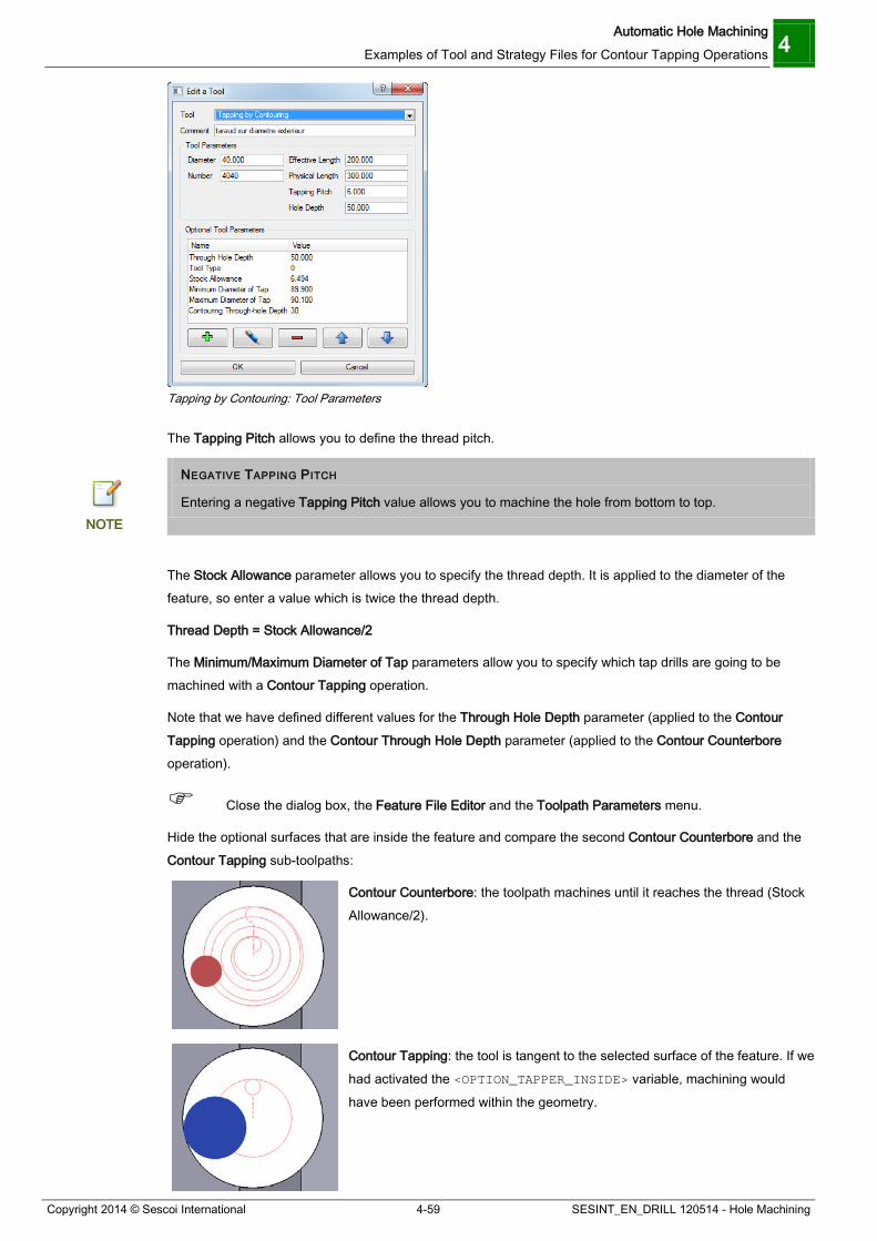
Automatic Hole Machining Examples of Tool and Strategy Files for Contour Tapping Operations 4
Copyright 2014 © Sescoi International 4-59 SESINT_EN_DRILL 120514 - Hole Machining
Tapping by Contouring: Tool Parameters
The Tapping Pitch allows you to define the thread pitch.
NEGATIVE TAPPING PITCH
Entering a negative Tapping Pitch value allows you to machine the hole from bottom to top. NOTE
The Stock Allowance parameter allows you to specify the thread depth. It is applied to the diameter of the feature, so enter a value which is twice the thread depth.
Thread Depth = Stock Allowance/2
The Minimum/Maximum Diameter of Tap parameters allow you to specify which tap drills are going to be machined with a Contour Tapping operation.
Note that we have defined different values for the Through Hole Depth parameter (applied to the Contour Tapping operation) and the Contour Through Hole Depth parameter (applied to the Contour Counterbore operation).
Close the dialog box, the Feature File Editor and the Toolpath Parameters menu.
Hide the optional surfaces that are inside the feature and compare the second Contour Counterbore and the Contour Tapping sub-toolpaths:
Contour Counterbore: the toolpath machines until it reaches the thread (Stock Allowance/2).
Contour Tapping: the tool is tangent to the selected surface of the feature. If we had activated the <OPTION_TAPPER_INSIDE> variable, machining would have been performed within the geometry.

4 Automatic Hole Machining Examples of Tool and Strategy Files for Contour Tapping Operations
SESINT_EN_DRILL 120514 - Hole Machining 4-60 Copyright 2014 © Sescoi International
You can also compare the machining depth of both sub-toolpaths.
CONTOUR TAPPING ON THE INNER DIAMETER (DRILLING DIAMETER)
The second toolpath is programmed to machine the 64 mm diameter feature, on the inner optional surface.
Optional Surfaces Inside the Feature Selected for Automatic Hole Machining
Open the Toolpath Parameters menu of this toolpath.
Click on the Edit button of the Machine Selection parameter.
Simple Thread FTS File: Tapper Inside
The <OPTION_TAPPER_INSIDE> variable is activated.
Close the Feature File Editor.

Automatic Hole Machining Examples of Tool and Strategy Files for Contour Tapping Operations 4
Copyright 2014 © Sescoi International 4-61 SESINT_EN_DRILL 120514 - Hole Machining
Click on the Edit button of the Tool Selection parameter.
In the Feature File Editor, go to the Tapping by Contouring section and select the 30 mm diameter tapper.
Click on the Edit button to have a look at the tool parameters.
Tapping by Contouring – second toolpath: Tool Parameters
This time, we have defined a negative Tapping Pitch value so that machining is done from the bottom to the top of the feature.
The thread depth has the same value.
Thread Depth = Stock Allowance/2
In this case, it can also be calculated this way: Thread Depth = (Thread Diameter – Drilling Diameter)/2
Close the dialog box, the Feature File Editor and the Toolpath Parameters menu.
You can compare the second Contour Counterbore and the Contour Tapping sub-toolpaths:
Contour Counterbore: the tool is tangent to the selected surface of the feature.
Contour Tapping: the threading passes are executed inside the selected feature. Here we have selected an optional surface but you can program a similar toolpath on activated surfaces. You only have to be sure that you are programming a thread milling strategy on the inner diameter (drilling diameter) of the feature.
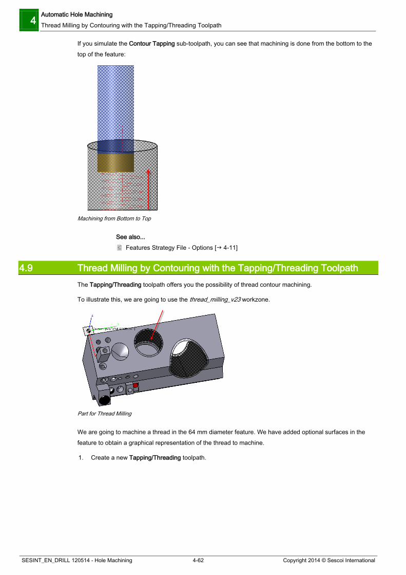
4 Automatic Hole Machining Thread Milling by Contouring with the Tapping/Threading Toolpath
SESINT_EN_DRILL 120514 - Hole Machining 4-62 Copyright 2014 © Sescoi International
If you simulate the Contour Tapping sub-toolpath, you can see that machining is done from the bottom to the top of the feature:
Machining from Bottom to Top
See also... Features Strategy File - Options [ 4-11]
4.9 Thread Milling by Contouring with the Tapping/Threading Toolpath The Tapping/Threading toolpath offers you the possibility of thread contour machining.
To illustrate this, we are going to use the thread_milling_v23 workzone.
Part for Thread Milling
We are going to machine a thread in the 64 mm diameter feature. We have added optional surfaces in the feature to obtain a graphical representation of the thread to machine.
1. Create a new Tapping/Threading toolpath.

Automatic Hole Machining Thread Milling by Contouring with the Tapping/Threading Toolpath 4
Copyright 2014 © Sescoi International 4-63 SESINT_EN_DRILL 120514 - Hole Machining
Tapping/Threading Toolpath in the Toolpath Strategy Dialog Box
2. In the Toolpath Parameters menu, click on the Straight button.
3. In the Define Cutter dialog box, use the Profile tab to import the thread_miller_Ø30 Cutter Profile.
4. Define the following Tip details:
Tip Details for Thread Milling Cutter
5. Click OK to validate and exit the dialog box.
6. Click on the <None> button in the Drilling/Boring End Points section and define the following point (top center of the feature):

4 Automatic Hole Machining Thread Milling by Contouring with the Tapping/Threading Toolpath
SESINT_EN_DRILL 120514 - Hole Machining 4-64 Copyright 2014 © Sescoi International
Top Center Point of the Feature
7. Enter 50 in the Depth Offset field to indicate the hole depth.
TAPPING/THREADING METHOD
1. Click on the button in the Tapping/Threading Method section.
The Tapping/Threading Method dialog box is displayed:
Tapping/Threading Method Dialog Box
2. Activate the Thread Milling option.

Automatic Hole Machining Thread Milling by Contouring with the Tapping/Threading Toolpath 4
Copyright 2014 © Sescoi International 4-65 SESINT_EN_DRILL 120514 - Hole Machining
Thread Milling Option
3. Enter the Diameter of the feature, here 64.
4. Leave the default value in the Pitch field.
5. Enter the Thread Depth, here 3.25.
6. Activate the Multipass Thread Depth option. This allows you to machine the thread with several passes.
7. Enter the Lateral Stepover, here 2.
8. Defining the Machining Method parameter whether you want to start machining the thread from the bottom (Climb) or from the top (Conventional). Here, we assume that you have pre-drilled the hole and you want to start machining from the bottom : activate the Climb option.
9. Deactivate the Use Cutter Compensation option.
Thread Milling Parameters

4 Automatic Hole Machining Thread Milling by Contouring with the Tapping/Threading Toolpath
SESINT_EN_DRILL 120514 - Hole Machining 4-66 Copyright 2014 © Sescoi International
10. Click OK to validate and exit the dialog box.
11. Validate the parameters and run the toolpath calculations.
You should obtain the following result:
Thread Milling Toolpath
Let’s see the toolpath result on the Stock Model:
1. Initialize a 3D User Block around the hole, as illustrated below:
Stock Model Initialization: User Block
2. Update the Stock Model with the toolpath.
You should obtain the following result:
Stock Updated with the Thread Milling Toolpath

Interactive Hole Machining Manual Hole Machining 5
Copyright 2014 © Sescoi International 5-1 SESINT_EN_DRILL 120514 - Hole Machining
5 Interactive Hole Machining
5.1 Manual Hole Machining If you do not wish to program an automatic hole machining toolpath, you can use the Manual Hole Machining function. It allows you to define a machining strategy on the fly, in accordance with your own preferences. Such a solution offers higher flexibility since you do not need to review the tool definition and strategy files.
The Manual Hole Machining function can be started after completing an automatic feature recognition.
To illustrate this function, create a new workzone from the angled_holes.xdw file and start an automatic feature recognition.
Angled Holes
After completing an automatic feature recognition using the standard parameters, 10 holes were found out.
Drilling Manager: No Recognized Features
First of all, you have to define the feature type. The two holes which are 10mm deep are bore drills.
1. Select both holes in the Drilling Manager.
2. Right click on the selection and select Bore Drill from the Type menu. We are now going to define a strategy to machine both of them.

5 Interactive Hole Machining Manual Hole Machining
SESINT_EN_DRILL 120514 - Hole Machining 5-2 Copyright 2014 © Sescoi International
Bore Drill Types
3. Click on the Manual button.
The Toolpath Parameters dialog box is displayed:
User Features
At the top of the dialog box, there are three tabs:
Feature Machining This tab allows you to build up the required strategy for the previously selected features.

Interactive Hole Machining Manual Hole Machining 5
Copyright 2014 © Sescoi International 5-3 SESINT_EN_DRILL 120514 - Hole Machining
Toolpath Parameters This tab allows you to set some toolpath parameters, such as security distances, starting Z, etc.
Feature Selection This tab displays the list of features that were previously selected in the Drilling Manager.
Let’s start by building up the machining strategy we will use to machine both bore drills, i.e. the sequence of operations to be completed. This is done in the Strategy Management frame with the Add Operations icons.
5.1.1 Defining a Hole Machining Strategy and Calculating Toolpath To build up the machining strategy of the two bore drills, we are going to complete centering first then simple drilling:
1. In the Add Operations section, click on the pre-drilling (centering) icon then on the drilling icon.
Operation Sequence
The sequence order of the operations is important since it determines the machining sequence. You can now define the details of each operation.
2. Select the relevant operation, here we are going to start with the Centering operation.
3. In the Parameters section, click on the Operation tab and define the required additional operation parameters.
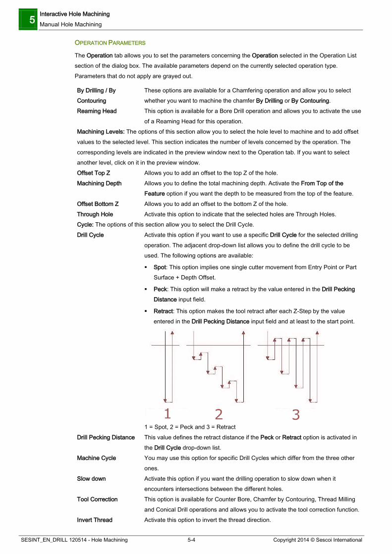
5 Interactive Hole Machining Manual Hole Machining
SESINT_EN_DRILL 120514 - Hole Machining 5-4 Copyright 2014 © Sescoi International
OPERATION PARAMETERS
The Operation tab allows you to set the parameters concerning the Operation selected in the Operation List section of the dialog box. The available parameters depend on the currently selected operation type. Parameters that do not apply are grayed out.
By Drilling / By Contouring
These options are available for a Chamfering operation and allow you to select whether you want to machine the chamfer By Drilling or By Contouring.
Reaming Head This option is available for a Bore Drill operation and allows you to activate the use of a Reaming Head for this operation.
Machining Levels: The options of this section allow you to select the hole level to machine and to add offset values to the selected level. This section indicates the number of levels concerned by the operation. The corresponding levels are indicated in the preview window next to the Operation tab. If you want to select another level, click on it in the preview window. Offset Top Z Allows you to add an offset to the top Z of the hole. Machining Depth Allows you to define the total machining depth. Activate the From Top of the
Feature option if you want the depth to be measured from the top of the feature. Offset Bottom Z Allows you to add an offset to the bottom Z of the hole. Through Hole Activate this option to indicate that the selected holes are Through Holes. Cycle: The options of this section allow you to select the Drill Cycle. Drill Cycle Activate this option if you want to use a specific Drill Cycle for the selected drilling
operation. The adjacent drop-down list allows you to define the drill cycle to be used. The following options are available:
Spot: This option implies one single cutter movement from Entry Point or Part Surface + Depth Offset.
Peck: This option will make a retract by the value entered in the Drill Pecking Distance input field.
Retract: This option makes the tool retract after each Z-Step by the value entered in the Drill Pecking Distance input field and at least to the start point.
1 = Spot, 2 = Peck and 3 = Retract
Drill Pecking Distance This value defines the retract distance if the Peck or Retract option is activated in the Drill Cycle drop-down list.
Machine Cycle You may use this option for specific Drill Cycles which differ from the three other ones.
Slow down Activate this option if you want the drilling operation to slow down when it encounters intersections between the different holes.
Tool Correction This option is available for Counter Bore, Chamfer by Contouring, Thread Milling and Conical Drill operations and allows you to activate the tool correction function.
Invert Thread Activate this option to invert the thread direction.

Interactive Hole Machining Manual Hole Machining 5
Copyright 2014 © Sescoi International 5-5 SESINT_EN_DRILL 120514 - Hole Machining
Drill Cycle Depth This value indicates the depth to be drilled before a retract movement is made if either the Peck or the Retract option is activated.
Diameter Allowance This option allows you to define a Diameter Allowance value. Diameter Pilot Hole This option allows you to define the diameter of an existing pilot hole. Chamfer Depth This option allows you to define the depth of a chamfer.
For a pre-drilling operation, this parameter may be activated and allows you to accomplish pre-drilling and chamfering in a single operation.
All the user-defined parameters are then displayed on a yellow background.
TOOL PARAMETERS
Features: Tool Parameters
When you create an operation for a Manual Hole Machining toolpath, this operation is added to the Operations list using a 'Generic Tool' with default characteristics. When you define a Strategy for a Stack or Stack Group, the operation is added with ‘Search in Tool Library’. The Tool menu allows the user to select the required tool for the current operation from the Tool Library or to create a tool definition on-the-fly and to set a number of optional parameters.
Click on this icon to call up the WorkNC Tool Library in which you can select or create the required tool.
Click on this icon to call up the Define Cutter dialog box which allows you to create a tool definition on-the-fly. In this case, the Select Cutter Type dialog box displays only the appropriate tools for the selected operation.
Click on this icon to recall the Define Cutter dialog box or the Tool Library if you want to change the cutter characteristics.

5 Interactive Hole Machining Manual Hole Machining
SESINT_EN_DRILL 120514 - Hole Machining 5-6 Copyright 2014 © Sescoi International
Clicking on this icon allows you to search for available tools in the Tool Library. You may then select the required tool in the Available Tools drop-down list situated just under the function icons. For the Auto User Strategy, if Tool Families have been defined in the Parameter 3 tab of the WorkNC Tool Library, a Search Tool Filter is available:
Search Tool Filter in the Tool Parameters Section
Activate the Tool Family option and select the required Family from the adjacent drop-down list. The […] button next to this list allows you to scan the Tool Library for available hole machining tool families.
The Check Thread Pitch option is available when you add a Tapping operation. When activated, it allows you to search for tappers whose Thread Pitch corresponds to the thread data of the corresponding feature.
Geometric Parameters
This dialog box section displays the characteristics of the currently selected tool and allows you to modify its characteristics.
To modify a value, double click on the required value field to activate it and enter the new value.
Optional Parameters
This dialog box allows you to set the optional parameters available for the selected tool type.
To change a value, double click on the value field in the corresponding Optional Parameter line to activate the input field and enter or select the desired value.
Holding the mouse cursor over the Tool Selection drop-down list displays an information box indicating the most important tool parameter values.
For our example, click on the icon to display the Define Cutter dialog box and create the required tool, here a 6mm spotting drill with the following parameters:
Features: Spotting Drill
Once you have defined both operation and tool parameters for the centering operation, repeat the same for the drilling step. This time, we are going to use a 10mm drill tool.

Interactive Hole Machining Manual Hole Machining 5
Copyright 2014 © Sescoi International 5-7 SESINT_EN_DRILL 120514 - Hole Machining
MISSING TOOLS: USE A GENERIC TOOL
Generic tools are used to generate toolpaths even if you do not have the relevant tool. NOTE
Features: Drilling Operation
Now that your machining strategy is fully defined, you can save it and use it again at any time:
Click on the icon in the Strategy Management section.
1. In the Strategy Name field, enter a name for your strategy.
2. Select the pathname in the Save Strategy in drop-down list. If necessary, define another path by clicking on the […] button.
3. In the Strategy Information section of the dialog box, select a Category, if defined. You may click on the Parameters button to create one.
4. Enter a Comment.
5. Click on the Save button.

5 Interactive Hole Machining Manual Hole Machining
SESINT_EN_DRILL 120514 - Hole Machining 5-8 Copyright 2014 © Sescoi International
Save Strategy
Click OK in the Toolpath Parameters dialog box.
Close the Drilling Manager.
The created toolpath is called Manual Hole Machining. If you had created the toolpath with the automatic function, it would have been called Automatic Hole Machining.
Click on the icon in front of the toolpath name to review the toolpath parameters.
Run the toolpath calculations.
You should obtain the following result:
Simple Drilling Toolpath
5.1.2 Practicing: Defining a Manual Thread Milling Strategy To illustrate this, we are going to use the Thread_milling workzone. We are going to program a manual strategy with a Contour Counterbore and a Contour Tapping operation. The toolpath will be programmed on the 64 mm diameter feature, considering that it is the thread diameter.
1. Open the Drilling Manager and select the appropriate feature.
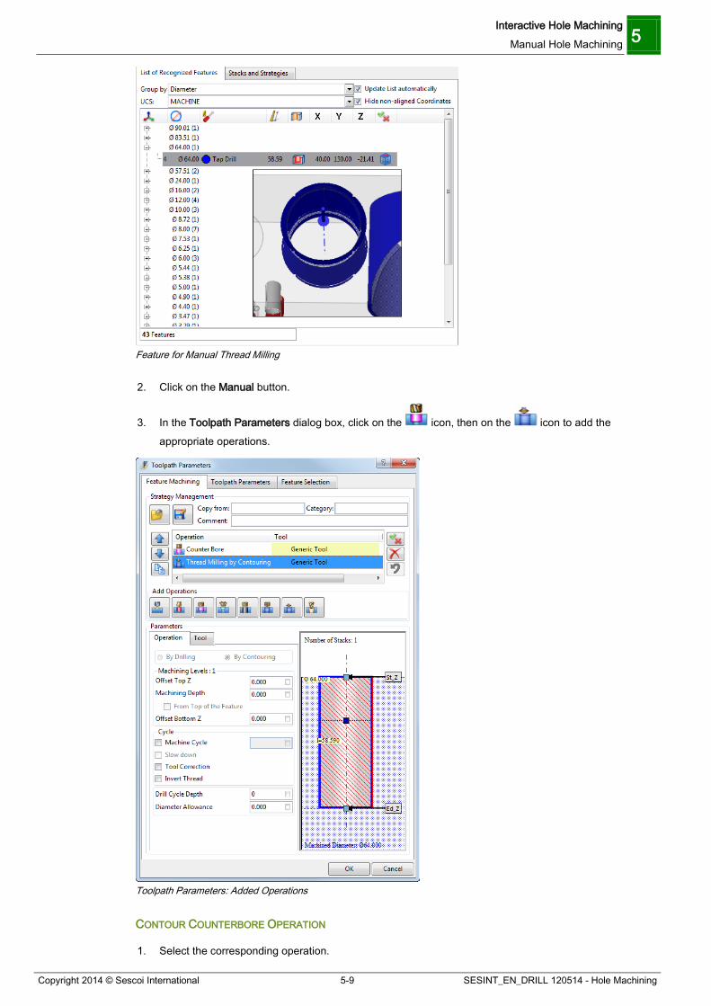
Interactive Hole Machining Manual Hole Machining 5
Copyright 2014 © Sescoi International 5-9 SESINT_EN_DRILL 120514 - Hole Machining
Feature for Manual Thread Milling
2. Click on the Manual button.
3. In the Toolpath Parameters dialog box, click on the icon, then on the icon to add the appropriate operations.
Toolpath Parameters: Added Operations
CONTOUR COUNTERBORE OPERATION
1. Select the corresponding operation.
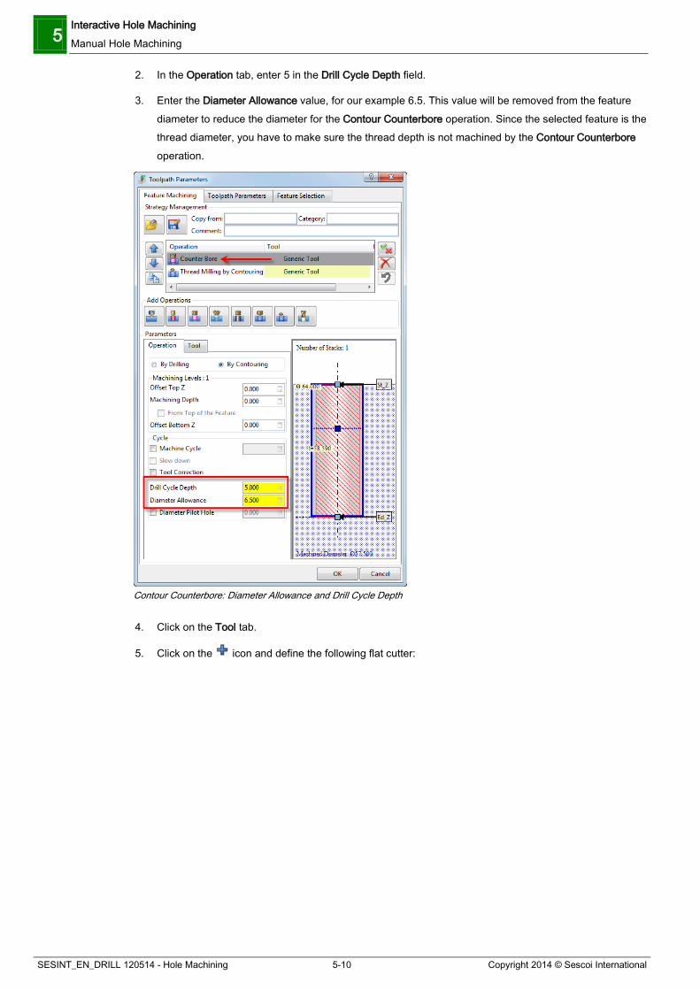
5 Interactive Hole Machining Manual Hole Machining
SESINT_EN_DRILL 120514 - Hole Machining 5-10 Copyright 2014 © Sescoi International
2. In the Operation tab, enter 5 in the Drill Cycle Depth field.
3. Enter the Diameter Allowance value, for our example 6.5. This value will be removed from the feature diameter to reduce the diameter for the Contour Counterbore operation. Since the selected feature is the thread diameter, you have to make sure the thread depth is not machined by the Contour Counterbore operation.
Contour Counterbore: Diameter Allowance and Drill Cycle Depth
4. Click on the Tool tab.
5. Click on the icon and define the following flat cutter:
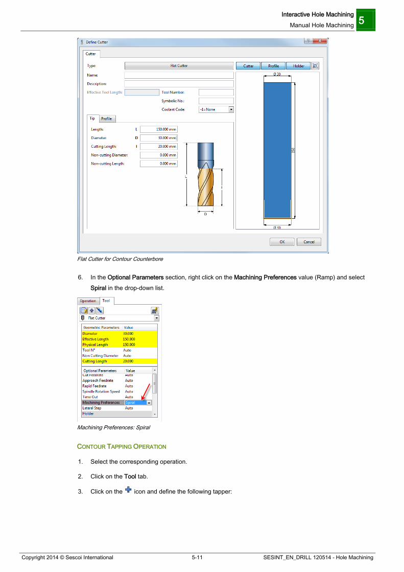
Interactive Hole Machining Manual Hole Machining 5
Copyright 2014 © Sescoi International 5-11 SESINT_EN_DRILL 120514 - Hole Machining
Flat Cutter for Contour Counterbore
6. In the Optional Parameters section, right click on the Machining Preferences value (Ramp) and select Spiral in the drop-down list.
Machining Preferences: Spiral
CONTOUR TAPPING OPERATION
1. Select the corresponding operation.
2. Click on the Tool tab.
3. Click on the icon and define the following tapper:
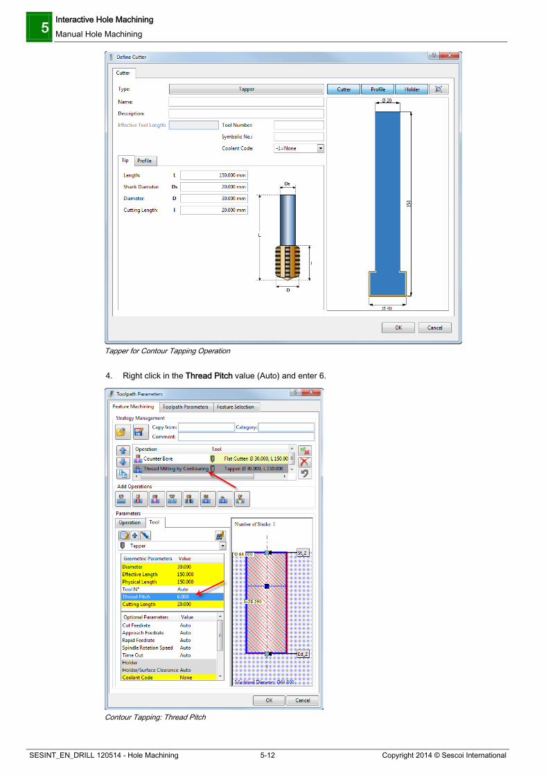
5 Interactive Hole Machining Manual Hole Machining
SESINT_EN_DRILL 120514 - Hole Machining 5-12 Copyright 2014 © Sescoi International
Tapper for Contour Tapping Operation
4. Right click in the Thread Pitch value (Auto) and enter 6.
Contour Tapping: Thread Pitch

Interactive Hole Machining Auto User Strategy 5
Copyright 2014 © Sescoi International 5-13 SESINT_EN_DRILL 120514 - Hole Machining
5. Click OK to validate.
6. Close the Drilling Manager and run the toolpath calculations.
You should obtain the following result:
Contour Counterbore Operation
Contour Tapping Operation
5.2 Auto User Strategy This process allows machining of complex features and stacks. It is divided into the following steps:
1. Defining recognition rules for stacks and complex feature recognition.
2. Applying these rules in the Automatic Feature Recognition process.
3. Defining and assigning machining strategies to the recognized features.
This is a very flexible and evolutive process allowing you to adapt your strategies to the current workpiece and tools available on the shopfloor.
This section will give an overview of the process. For detailed information about the different dialog boxes, press the [F1] key to open the Online Help of the application.
5.2.1 Defining Recognition Rules To illustrate this, we are going to use the Angled_holes.xdw CAD file.
Angled Holes

5 Interactive Hole Machining Auto User Strategy
SESINT_EN_DRILL 120514 - Hole Machining 5-14 Copyright 2014 © Sescoi International
1. Create a workzone from the CAD file.
2. Open the Drilling Manager.
3. Click on the Sort button.
4. Press the [Ctrl] + [A] keys to select the whole part and validate.
By default, no part Features are recognized.
Drilling Manager: No Recognized Features
You can use the context menu of each separate Feature and select their type in the Type menu.
You can also open the Drilling Function Parameters and use the Type Rule Definition function.
Click on the Parameters button.
In the Drilling Function Parameters dialog box, click on the Recognition Options tab.
Drilling Function Parameters: Recognition Options Tab
Click on the Rule Definition button.
The Type Rule Definition dialog box is displayed:

Interactive Hole Machining Auto User Strategy 5
Copyright 2014 © Sescoi International 5-15 SESINT_EN_DRILL 120514 - Hole Machining
Type Rules Definition Dialog Box
This dialog box allows you to define diameter ranges and shapes in order to recognize specific complex Drill Types and attach Strategies to the Recognition Rules (in CAM mode).
Rules are Configuration dependent. The Configuration drop-down list at the top of the dialog box allows you to select the Configuration for which you want to define a new Rule or modify an existing one.
On the left side of this dialog box, a number of icons allow you to create, delete and reorder the different elements of a Drill Type Recognition Rule.
The pane on the left side lists all the created rules and displays details about the corresponding sub-levels. Click on the [+] box next to the Rule name to expand the display to the sub-levels to visualize their parameters such as Diameter, Depth and Angle ranges. Click on the [-] box to reduce display to the Rule name.
If a Strategy has been attached to a Rule definition, its name is displayed in blue with the symbol next to its name and the Strategy name is added between brackets.
The center section of the dialog box allows you to specify the different parameters used for each sub-level.
The right pane of the dialog box displays a schematic preview of the defined stacks with the respective colors of the defined Drill Type. A black arrow indicates the active level. This level is also highlighted in the list pane. You may select another level by simply clicking on it in the preview window.
When in CAM mode, the additional Strategy section is displayed in the dialog box. It allows you to define one or several machining strategies for a particular complex Drill Type which may later be selected for machining.
Let’s suppose that you want to create a rule to automatically type the 3 following stacks on the part:
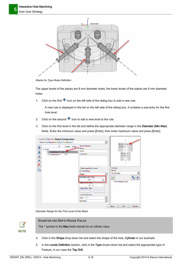
5 Interactive Hole Machining Auto User Strategy
SESINT_EN_DRILL 120514 - Hole Machining 5-16 Copyright 2014 © Sescoi International
Stacks for Type Rules Definition
The upper levels of the stacks are 8 mm diameter holes, the lower levels of the stacks are 6 mm diameter holes.
1. Click on the first icon on the left side of the dialog box to add a new rule.
A new rule is displayed in the list on the left side of the dialog box. It contains a sub-entry for the first hole level.
2. Click on the second icon to add a new level to the rule.
3. Click on the first level in the list and define the appropriate diameter range in the Diameter (Min-Max) fields. Enter the minimum value and press [Enter], then enter maximum value and press [Enter].
Diameter Range for the First Level of the Stack
DIAMETER AND DEPTH RANGE FIELDS
The * symbol in the Max fields stands for an infinite value. NOTE
4. Click in the Shape drop-down list and select the shape of the hole, Cylinder in our example.
5. In the Levels Definition section, click in the Type drown-down list and select the appropriate type of Feature, in our case the Tap Drill.

Interactive Hole Machining Auto User Strategy 5
Copyright 2014 © Sescoi International 5-17 SESINT_EN_DRILL 120514 - Hole Machining
Type Definition for the First Level of the Stack
6. Define the diameter range and the type of the second level of the stack, which a simple Drill.
Diameter and Type Definition for the Second Level of the Stack
7. Enter the Name of the rule in the corresponding field and press [Enter]. We recommend you to use explicit names.
8. Click OK to validate and exit the Type Rules Definition dialog box.
You are back in the Recognition Options tab.
DRILL RECOGNITION COMMAND OPTIONS Use Multi-level Recognition Activate this option to recognize multi-level holes. If this option is not active,
recognition is made for the different individual features only without considering stack definitions and the associated strategies from the Rules Definition.
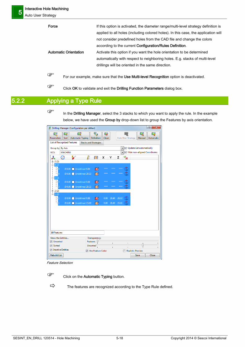
5 Interactive Hole Machining Auto User Strategy
SESINT_EN_DRILL 120514 - Hole Machining 5-18 Copyright 2014 © Sescoi International
Force If this option is activated, the diameter range/multi-level strategy definition is applied to all holes (including colored holes). In this case, the application will not consider predefined holes from the CAD file and change the colors according to the current Configuration/Rules Definition.
Automatic Orientation Activate this option if you want the hole orientation to be determined automatically with respect to neighboring holes. E.g. stacks of multi-level drillings will be oriented in the same direction.
For our example, make sure that the Use Multi-level Recognition option is deactivated.
Click OK to validate and exit the Drilling Function Parameters dialog box.
5.2.2 Applying a Type Rule
In the Drilling Manager, select the 3 stacks to which you want to apply the rule. In the example below, we have used the Group by drop-down list to group the Features by axis orientation.
Feature Selection
Click on the Automatic Typing button.
The features are recognized according to the Type Rule defined.

Interactive Hole Machining Auto User Strategy 5
Copyright 2014 © Sescoi International 5-19 SESINT_EN_DRILL 120514 - Hole Machining
Feature Recognized after Automatic Typing
TYPING FEATURES AND MACHINING STRATEGY
Once the Features have been recognized with the rules defined in the Type Rules Definition dialog box, you can machine them in the automatic, manual or manual-auto mode. NOTE
5.2.3 Defining a Strategy to Machine the Recognized Features
In the Drilling Manager, click on the Stacks and Strategies tab.
Drilling Manager: Stacks and Strategies Tab
The stacks are stored into two groups: one with the recognized features, the other with the unrecognized features.
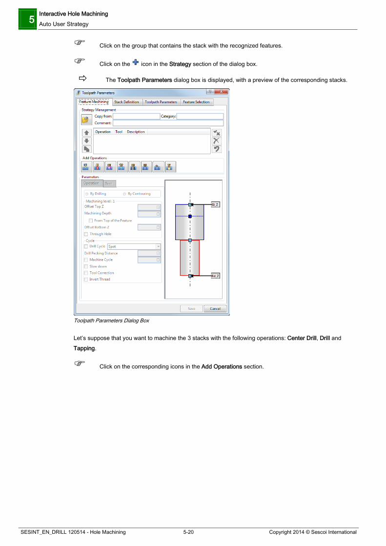
5 Interactive Hole Machining Auto User Strategy
SESINT_EN_DRILL 120514 - Hole Machining 5-20 Copyright 2014 © Sescoi International
Click on the group that contains the stack with the recognized features.
Click on the icon in the Strategy section of the dialog box.
The Toolpath Parameters dialog box is displayed, with a preview of the corresponding stacks.
Toolpath Parameters Dialog Box
Let’s suppose that you want to machine the 3 stacks with the following operations: Center Drill, Drill and Tapping.
Click on the corresponding icons in the Add Operations section.

Interactive Hole Machining Auto User Strategy 5
Copyright 2014 © Sescoi International 5-21 SESINT_EN_DRILL 120514 - Hole Machining
Toolpath Parameters: Operations
In the Parameters section, click on the Tool tab.
This tab allows to set parameters concerning the tool to be used by each operation.
Toolpath Parameters: Tool Tab
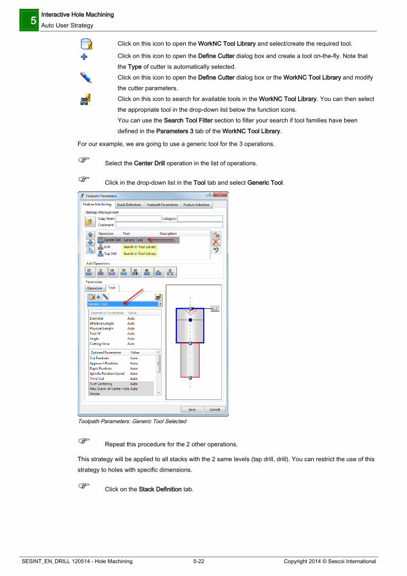
5 Interactive Hole Machining Auto User Strategy
SESINT_EN_DRILL 120514 - Hole Machining 5-22 Copyright 2014 © Sescoi International
Click on this icon to open the WorkNC Tool Library and select/create the required tool.
Click on this icon to open the Define Cutter dialog box and create a tool on-the-fly. Note that the Type of cutter is automatically selected.
Click on this icon to open the Define Cutter dialog box or the WorkNC Tool Library and modify the cutter parameters.
Click on this icon to search for available tools in the WorkNC Tool Library. You can then select the appropriate tool in the drop-down list below the function icons. You can use the Search Tool Filter section to filter your search if tool families have been defined in the Parameters 3 tab of the WorkNC Tool Library.
For our example, we are going to use a generic tool for the 3 operations.
Select the Center Drill operation in the list of operations.
Click in the drop-down list in the Tool tab and select Generic Tool.
Toolpath Parameters: Generic Tool Selected
Repeat this procedure for the 2 other operations.
This strategy will be applied to all stacks with the 2 same levels (tap drill, drill). You can restrict the use of this strategy to holes with specific dimensions.
Click on the Stack Definition tab.
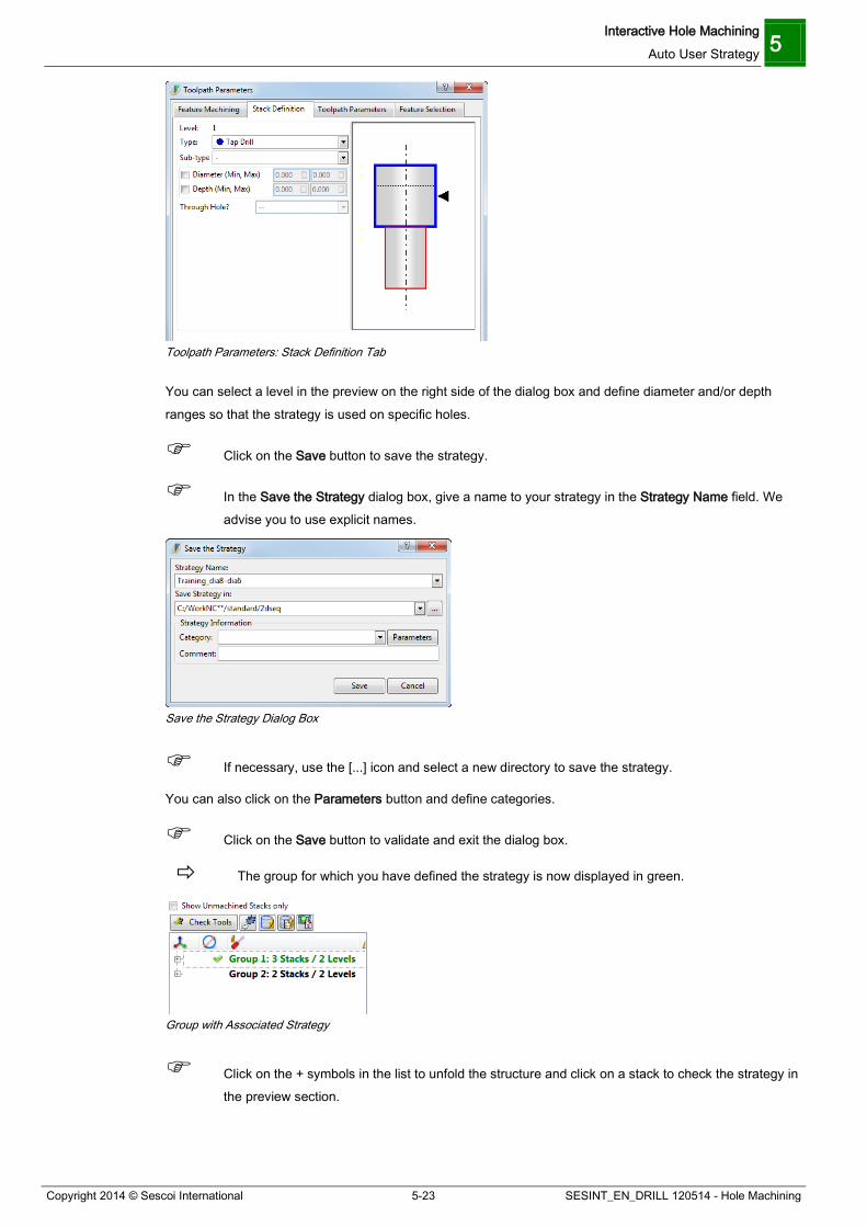
Interactive Hole Machining Auto User Strategy 5
Copyright 2014 © Sescoi International 5-23 SESINT_EN_DRILL 120514 - Hole Machining
Toolpath Parameters: Stack Definition Tab
You can select a level in the preview on the right side of the dialog box and define diameter and/or depth ranges so that the strategy is used on specific holes.
Click on the Save button to save the strategy.
In the Save the Strategy dialog box, give a name to your strategy in the Strategy Name field. We advise you to use explicit names.
Save the Strategy Dialog Box
If necessary, use the [...] icon and select a new directory to save the strategy.
You can also click on the Parameters button and define categories.
Click on the Save button to validate and exit the dialog box.
The group for which you have defined the strategy is now displayed in green.
Group with Associated Strategy
Click on the + symbols in the list to unfold the structure and click on a stack to check the strategy in the preview section.

5 Interactive Hole Machining Auto User Strategy
SESINT_EN_DRILL 120514 - Hole Machining 5-24 Copyright 2014 © Sescoi International
Stack and Associated Strategy
Select the whole group in the list and click on the Auto User Strategy button.
3 toolpaths are added to the Workzone Manager.
Click on the Close button and run the toolpath calculations.
You should obtain the following result:
Manual Hole Machining Toolpaths

Interactive Hole Machining Auto User Strategy 5
Copyright 2014 © Sescoi International 5-25 SESINT_EN_DRILL 120514 - Hole Machining
5.2.4 Managing Strategies
ASSIGNING A STRATEGY TO A RECOGNITION RULE
If you have defined a strategy that you want to systematically use on specific stacks, you can assign this strategy to the corresponding recognition rule.
Let’s suppose that you want to assign the strategy we have just defined to the recognition rule we have created for the 3 stacks in the angled_holes part.
1. Open the Drilling Manager.
2. Activate the Stacks and Strategies tab and select the group containing the 3 stacks.
3. Click on the icon.
4. Select your strategy in the drop-down list on the right side of the Type Rules Definition dialog box.
5. Click on the icon to assign the strategy.
The recognition rule in the list now has a icon to indicate that the strategy has been assigned.
Type Rules Definition: Strategy Assigned
When you select the stack to which the strategy is attached, a icon is displayed to indicate that the corresponding strategy is assigned to a rule:
Strategy Assigned to a Rule
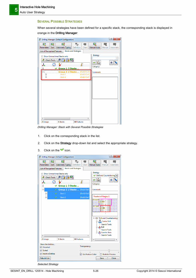
5 Interactive Hole Machining Auto User Strategy
SESINT_EN_DRILL 120514 - Hole Machining 5-26 Copyright 2014 © Sescoi International
SEVERAL POSSIBLE STRATEGIES
When several strategies have been defined for a specific stack, the corresponding stack is displayed in orange in the Drilling Manager:
Drilling Manager: Stack with Several Possible Strategies
1. Click on the corresponding stack in the list.
2. Click on the Strategy drop-down list and select the appropriate strategy.
3. Click on the icon.
Selected Strategy
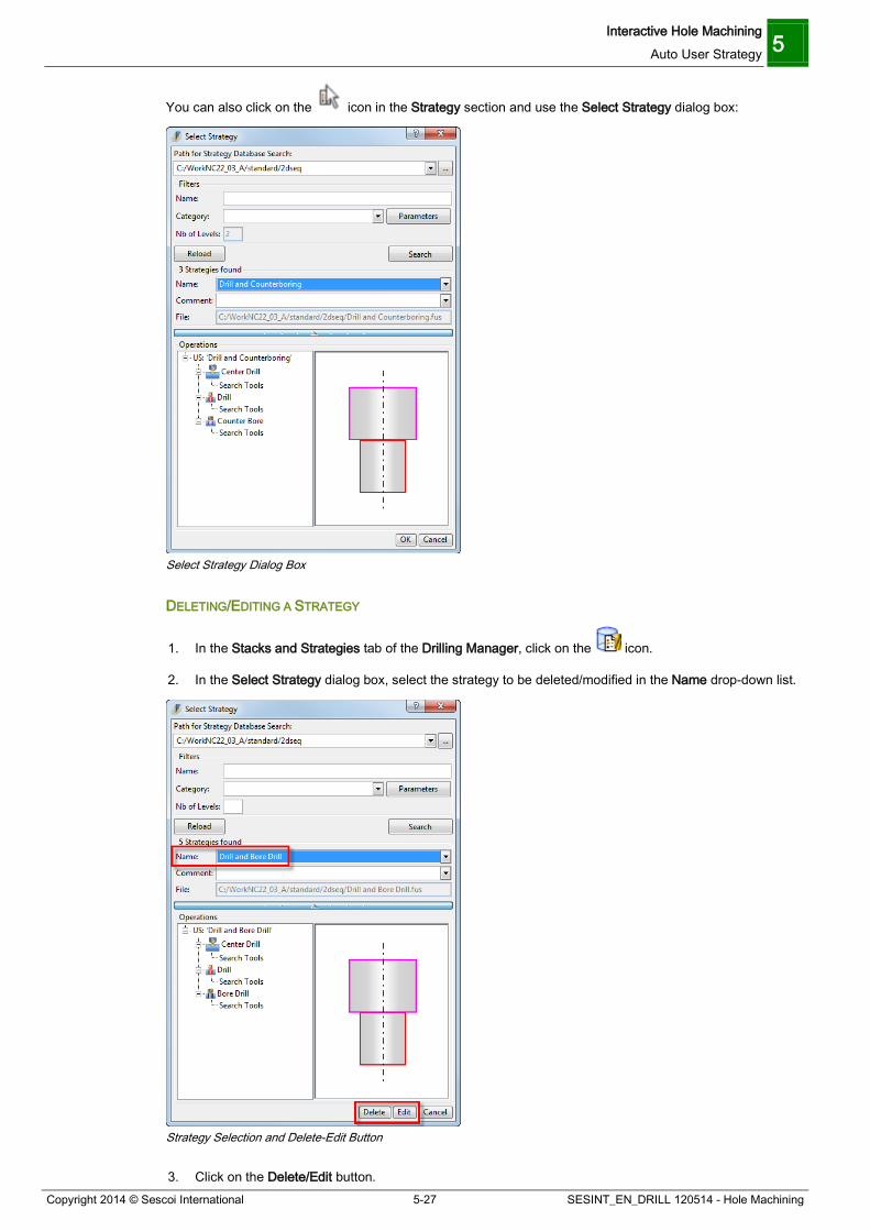
Interactive Hole Machining Auto User Strategy 5
Copyright 2014 © Sescoi International 5-27 SESINT_EN_DRILL 120514 - Hole Machining
You can also click on the icon in the Strategy section and use the Select Strategy dialog box:
Select Strategy Dialog Box
DELETING/EDITING A STRATEGY
1. In the Stacks and Strategies tab of the Drilling Manager, click on the icon.
2. In the Select Strategy dialog box, select the strategy to be deleted/modified in the Name drop-down list.
Strategy Selection and Delete-Edit Button
3. Click on the Delete/Edit button.
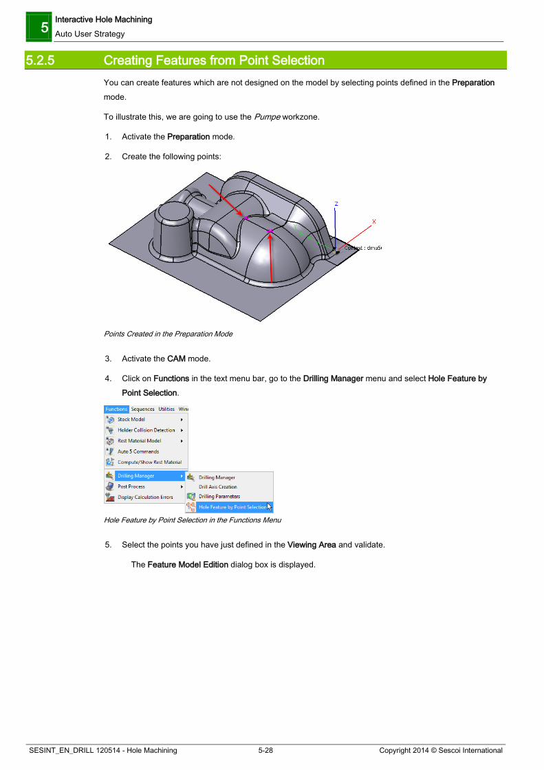
5 Interactive Hole Machining Auto User Strategy
SESINT_EN_DRILL 120514 - Hole Machining 5-28 Copyright 2014 © Sescoi International
5.2.5 Creating Features from Point Selection You can create features which are not designed on the model by selecting points defined in the Preparation mode.
To illustrate this, we are going to use the Pumpe workzone.
1. Activate the Preparation mode.
2. Create the following points:
Points Created in the Preparation Mode
3. Activate the CAM mode.
4. Click on Functions in the text menu bar, go to the Drilling Manager menu and select Hole Feature by Point Selection.
Hole Feature by Point Selection in the Functions Menu
5. Select the points you have just defined in the Viewing Area and validate.
The Feature Model Edition dialog box is displayed.

Interactive Hole Machining Auto User Strategy 5
Copyright 2014 © Sescoi International 5-29 SESINT_EN_DRILL 120514 - Hole Machining
Feature Model Edition Dialog Box
6. Define the features to be applied to the selected points.
Defined Features
7. Click on the Save button.
8. Click OK to validate and exit the dialog box.
Now you have to select a View or a planar surface to determine to determine the drilling axis.
9. Select the following surface and validate:

5 Interactive Hole Machining Auto User Strategy
SESINT_EN_DRILL 120514 - Hole Machining 5-30 Copyright 2014 © Sescoi International
Planar Surface Selection for Drilling Axis Definition
The drilling axis will be perpendicular to this surface.
10. Answer Yes to the message which invites you to open the Drilling Manager.
11. In the Drilling Manager, activate the Stacks and Strategy Tab.
12. Create/Select your strategy and assign it.
Strategy Defined
13. Click on the Auto User Strategy button.
14. Close the Drilling Manager and run the toolpath calculations.
You should obtain the following result:
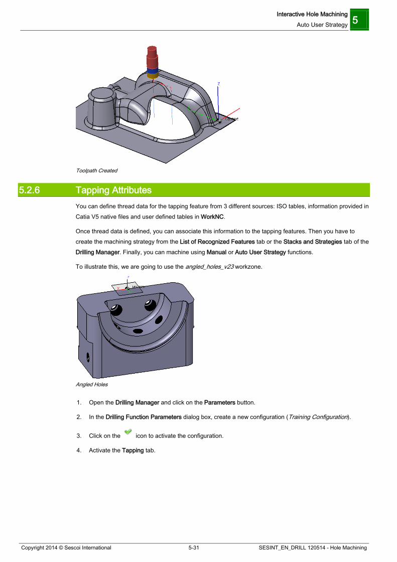
Interactive Hole Machining Auto User Strategy 5
Copyright 2014 © Sescoi International 5-31 SESINT_EN_DRILL 120514 - Hole Machining
Toolpath Created
5.2.6 Tapping Attributes You can define thread data for the tapping feature from 3 different sources: ISO tables, information provided in Catia V5 native files and user defined tables in WorkNC.
Once thread data is defined, you can associate this information to the tapping features. Then you have to create the machining strategy from the List of Recognized Features tab or the Stacks and Strategies tab of the Drilling Manager. Finally, you can machine using Manual or Auto User Strategy functions.
To illustrate this, we are going to use the angled_holes_v23 workzone.
Angled Holes
1. Open the Drilling Manager and click on the Parameters button.
2. In the Drilling Function Parameters dialog box, create a new configuration (Training Configuration).
3. Click on the icon to activate the configuration.
4. Activate the Tapping tab.

5 Interactive Hole Machining Auto User Strategy
SESINT_EN_DRILL 120514 - Hole Machining 5-32 Copyright 2014 © Sescoi International
Drilling Function Parameters: Tapping Tab
This tab contains pre-defined tapping tables. You can view information of these tables by clicking on the + symbols.
Defining Tapping Tables The required data is:
The thread Pitch. The pre-drill diameter (CAD Drill Ø or Drilled Ø) which is calculated depending on how the
threaded hole is defined in the CAD application (Tapper Inside or Tapper Outside). Tapper Inside: nominal hole diameter before tapping operation. Tapper Outside: maximum hole diameter after tapping operation.
The Depth Difference which indicates the depth to be added to the pre-drill operation with respect to the depth of the thread.
To add a new tapping table, click on the icon. Double click on the new line which appears in the list of tables and rename it.
To add a new diameter definition, click on the tapping table in the list, then click on the icon. Double click on the various columns to enter the corresponding values.
For our example, add two new tapping tables with diameter definitions as illustrated below:
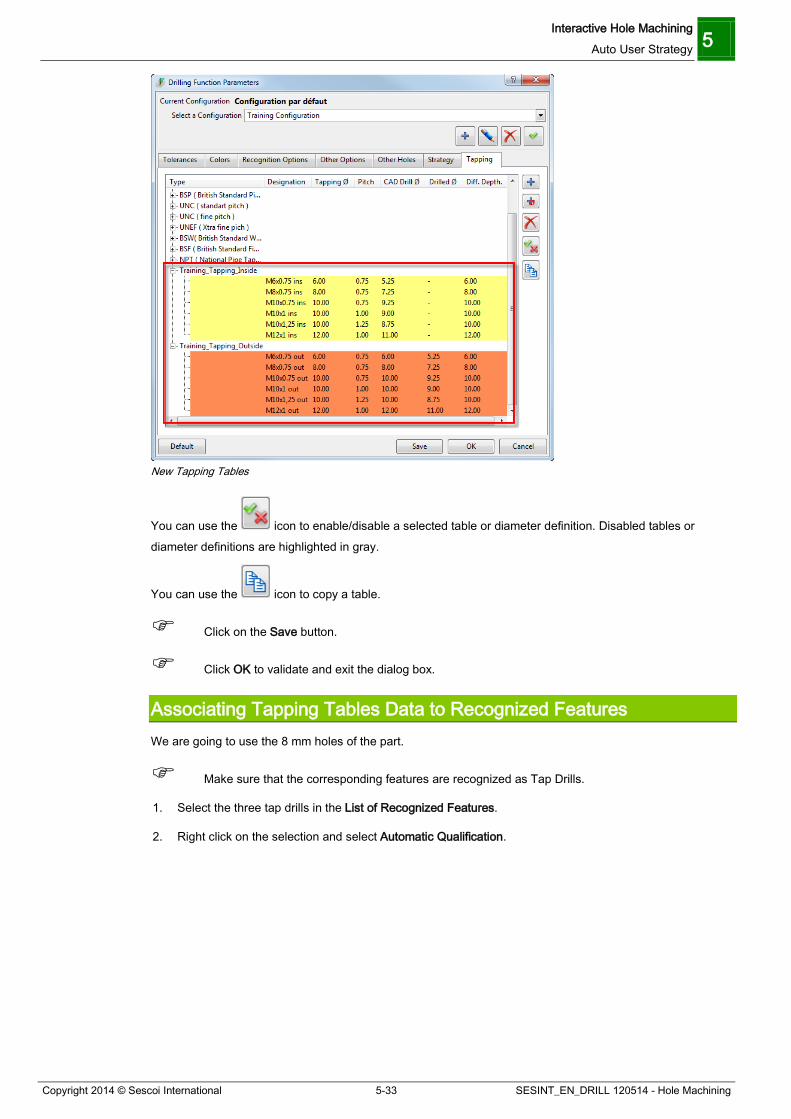
Interactive Hole Machining Auto User Strategy 5
Copyright 2014 © Sescoi International 5-33 SESINT_EN_DRILL 120514 - Hole Machining
New Tapping Tables
You can use the icon to enable/disable a selected table or diameter definition. Disabled tables or diameter definitions are highlighted in gray.
You can use the icon to copy a table.
Click on the Save button.
Click OK to validate and exit the dialog box.
Associating Tapping Tables Data to Recognized Features We are going to use the 8 mm holes of the part.
Make sure that the corresponding features are recognized as Tap Drills.
1. Select the three tap drills in the List of Recognized Features.
2. Right click on the selection and select Automatic Qualification.
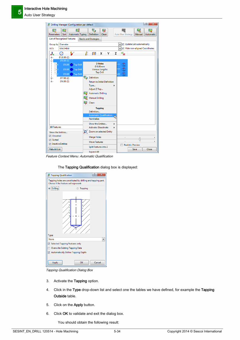
5 Interactive Hole Machining Auto User Strategy
SESINT_EN_DRILL 120514 - Hole Machining 5-34 Copyright 2014 © Sescoi International
Feature Context Menu: Automatic Qualification
The Tapping Qualification dialog box is displayed:
Tapping Qualification Dialog Box
3. Activate the Tapping option.
4. Click in the Type drop-down list and select one the tables we have defined, for example the Tapping Outside table.
5. Click on the Apply button.
6. Click OK to validate and exit the dialog box.
You should obtain the following result:

Interactive Hole Machining Auto User Strategy 5
Copyright 2014 © Sescoi International 5-35 SESINT_EN_DRILL 120514 - Hole Machining
Tapping Table Associated to the Features
Note that you can right click on these features and select Reinitialize to remove the associated tapping table.
You can now machine using the Manual and Auto User Strategy.

Index
Copyright 2014 © Sescoi International i SESINT_EN_DRILL 120514 - Hole Machining
Index
A
Applying a Type Rule, 3-4, 5-25 Associating Tapping Tables Data to Recognized Features, 5-50 Auto User Strategy, 5-18 Automatic Feature Recognition, 3-1 Automatic Hole Machining, 4-1 C
Checking the Use of Sub-Strategies, 4-72 Configuration Files required for Automatic Hole Machining, 4-5 Create Automatic Hole Machining Toolpath from a 2D File, 4-49 Creating a User-defined Strategy, 4-59 Creating Features from Point Selection, 5-42 Creating Tools for Sub-strategies, 4-70 D
Declaring additional Types of Holes, 4-55 Defining a Hole Machining Strategy and Calculating Toolpath, 5-5 Defining a Strategy to Machine the Recognized Features, 5-27 Defining Recognition Rules, 3-4, 5-18 Defining Tapping Tables, 5-49 Drilling Function Parameters, 3-5 Drilling Function Parameters - Colors Tab, 3-11 Drilling Function Parameters - Other Holes Tab, 3-16 Drilling Function Parameters - Other Options Tab, 3-13 Drilling Function Parameters - Recognition Options Tab, 3-12 Drilling Function Parameters - Strategy Tab, 3-20 Drilling Function Parameters - Tapping Tab, 3-23 Drilling Function Parameters - Tolerances Tab, 3-6 E
Example of a Features Definition File, 4-8 Example of a Tool Configuration File, 4-24
Examples of Tool and Strategy Files for Contour Tapping Operations, 4-74 F
Features Definition File (*.ftd), 4-6 Features Strategy File - Options, 4-12, 4-83 H
Hole Machining with Point Files, 4-37 I Interactive Hole Machining, 5-1 Introduction to Hole Machining, 2-1 M
Managing Strategies, 5-36 Manual Hole Machining, 5-1 Moving Recognized Features, 3-25 P
Practicing: Defining a Manual Thread Milling Strategy, 5-12 Practicing: Machine Conical Holes, 4-30 Preview of the FTD File, 4-2 Programming your First Hole Machining Toolpath, 4-1 S
Solution: Machine Conical Holes, 4-31 Strategy Configuration File (*.fts), 4-9 Strategy Configuration File Samples, 4-9 T
Tapping Attributes, 5-47 Thread Milling by Contouring with the Tapping/Threading Toolpath, 4-83 Tool Configuration File (*.ftt), 4-16 Tool Parameter Definition, 4-16 Tool Parameters available in Drill Strategies, 4-22 U
User-defined Strategies for Automatic Hole Machining, 4-54 W
WorkNC Features: Points at bottom of Holes, 4-46 WorkNC Features: Points at Hole Top, 4-37

(c) Copyright 1998-2014 Sescoi International. All rights reserved.
IDDN.FR.001.300009.018.S.P.1993.000.30640.
This work is registered at the Agence pour la Protection des Programmes (Agency for the Protection of Software Programs), 249 rue de Crimée, 75019 Paris, France.
It is protected in France by the intellectual property Code and, abroad, by the international conventions on copyright. Any copyright infringement of this work is a counterfeiting offense and it is liable to punishment in France under the article 335-2 of the intellectual property Code and to imprisonment and/or payment of a fine. The APP is appointed by the holder of the rights to apply sanctions for any unauthorized copy and/or use.
Use of the WorkNC software program is subject to the terms and conditions of the License Agreement. This software can only be used on or from the computer and at or from the address defined on the License Agreement. It is prohibited to move, copy, resell, disassemble, decompile, reverse engineer or modify this software. The user is authorized to make a single backup copy of the software. The user is responsible for the physical protection of this copy.
Sescoi and WorkNC are registered trademarks of Sescoi International.
Other product names mentioned in this manual are registered trademarks of their respective companies.
The WorkNC software is a dual-use item (Category: 2D001): “item submitted to the export authorization in case of export outside the European Community”.
Portions of this SOFTWARE are owned by Siemens Product Lifecycle Management SOFTWARE Inc.
© 1986 - 2014. All Rights Reserved.
Sescoi International Sescoi USA, Inc. Sescoi France Sescoi Iberia, S.L. Sescoi R+D Sescoi India Solutions Private Limited Sescoi GmbH Sescoi (Shanghai) Trading Company Ltd (Sescoi
China) Sescoi KK Sescoi South Korea (Branch Office) Sescoi Brasil