Training Document for SIMIT SCE - w3.siemens.com · Training Document for SIMIT SCE MODULE G1...
52
Industrial Solutions and Services Training Document for SIMIT SCE MODULE G1 'Startup' Plant Simulation with SIMIT SCE Training Document for SIMIT SCE Page 1 of 51 Module G1 Issued: 02/2008 ‘Startup’ Plant Simulation with SIMIT SCE
Transcript of Training Document for SIMIT SCE - w3.siemens.com · Training Document for SIMIT SCE MODULE G1...
Industrial Solutions and Services
Training Document for SIMIT SCE
MODULE G1
'Startup' Plant Simulation with SIMIT SCE
Training Document for SIMIT SCE Page 1 of 51 Module G1 Issued: 02/2008 ‘Startup’ Plant Simulation with SIMIT SCE

Industrial Solutions and Services
Issued
02/2008
Trademarks SIMIT® is a registered trademark of Siemens AG. The other designations in this document can be trademarks or registered names, whose use by third parties for their own purposes can violate the rights of the owners.
Copyright © Siemens AG 20097 All rights reserved Transmitting, using or reproducing this document is only permitted within public training and educational facilities. Exceptions require the prior written approval of I&S IS E&C IT OOP 1 (E-mail: [email protected]). Use or transmission of its contents, above and beyond this, are not permitted unless express written permission has been obtained. Offenders will be liable for damages. All rights, including the right to translate the document, are reserved, especially rights created by patent grant or registration of a utility model. Siemens AG Industrial Solutions and Services Engineering & Construction Industrial IT Solutions Simulation Center
Exclusion of liability
We have checked the contents of this manual for agreement with the hardware and software described. Since deviations cannot be precluded entirely, we cannot guarantee full agreement. However, the data in this manual are reviewed regularly and any necessary corrections included in subsequent editions. Suggestions for improvements are welcomed.
© Siemens AG 2009
Subject to change.
This document has been written by Siemens I&S IT PS (Industrial Solutions and Services, IT Plant Solutions) for training purposes. We would like to thank Michael Dziallas Engineering for its support in preparing this document.
Training Document for SIMIT SCE Page 2 of 51 Module G1 Issued: 02/2008 ‘Startup’ Plant Simulation with SIMIT SCE

Industrial Solutions and Services
Contents
1. PREFACE.....................................................................................................................................................5
2. GENERAL INFORMATION ABOUT SIMIT SCE.........................................................................................7
2.1 SIMIT SCE ................................................................................................................................................7 2.2 Configuring the SIMIT SCE.......................................................................................................................8
3. INSTALLING THE SIMIT SCE SOFTWARE ...............................................................................................9
3.1 Installation .................................................................................................................................................9
4. STARTING SIMIT SCE ..............................................................................................................................10
5. MANAGING AND CREATING PROJECTS ..............................................................................................11
5.1 The Operator Interface............................................................................................................................11 5.2 Status Bar ...............................................................................................................................................12 5.3 Message Line..........................................................................................................................................12 5.4 Index column...........................................................................................................................................13
6. VENTILATOR PROJECT...........................................................................................................................15
6.1 Setting up a new project .........................................................................................................................16 6.2 Opening the PLCSim Gateway...............................................................................................................16 6.3 Setting up a diagram...............................................................................................................................19 6.4 Creating an operating window ................................................................................................................25 6.5 Drawing the fan impeller .........................................................................................................................29 6.6 Creating a SIMIT SCE project simulation ...............................................................................................32 6.7 Creating a PLC program.........................................................................................................................33 6.8 Starting PLCSIM and loading the PLC program.....................................................................................37 6.9 Simulation with SIMIT SCE.....................................................................................................................38 6.10 Simulation by means of the operating window....................................................................................40 6.11 Simulation by means of the diagram...................................................................................................41
7. CONNECTION TO THE REAL PLC ..........................................................................................................42
7.1 Changing the address in the SIMIT SCE project ....................................................................................43 7.2 Address changes in the Step7 program .................................................................................................46
8. SIGNAL GROUPS AND GRAPHS ............................................................................................................48
8.1 Signal groups ..........................................................................................................................................48 8.2 Graph ......................................................................................................................................................51
Training Document for SIMIT SCE Page 3 of 51 Module G1 Issued: 02/2008 ‘Startup’ Plant Simulation with SIMIT SCE
Industrial Solutions and Services
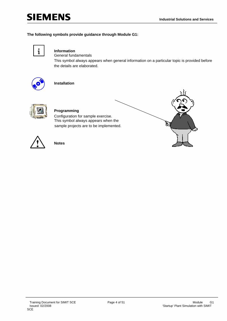
The following symbols provide guidance through Module G1: Information General fundamentals
This symbol always appears when general information on a particular topic is provided before the details are elaborated.
Installation Programming Configuration for sample exercise.
This symbol always appears when the sample projects are to be implemented.
Notes
Training Document for SIMIT SCE Page 4 of 51 Module G1 Issued: 02/2008 ‘Startup’ Plant Simulation with SIMIT SCE

Industrial Solutions and Services
1. PREFACE
In terms of its contents, the SIMIT SCE module is part of the teaching unit entitled 'Plant Simulation with SIMIT SCE' and is intended to serve as a quick introduction to plant simulation.
Basic Principles of STEP 7 Programming 2 to 3 days Modules A
Industrial Field Bus Systems 2 to 3 days Modules D
Further Functions of STEP 7 Programming 2 to 3 days Modules B
Process Visualization 2 to 3 days Modules F
Plant Simulation with SIMIT SCE 1 to 2 days Modules G
Programming Languages 2 to 3 days Modules C
IT Communication with SIMATIC S7 1 to 2 days Modules E
Learning Objective: In Module G1, the reader learns how to use the SIMIC SCE software tool. The module explains the basic principles and shows the reader how to handle and create projects on the basis of detailed examples. Requirements: To successfully work through Module G1, the following knowledge is assumed: • Knowledge in the use of Windows • Basics of PLC programming with STEP 7 (e.g. Module A3 – 'Startup'
PLC Programming with STEP 7)
Training Document for SIMIT SCE Page 5 of 51 Module G1 Issued: 02/2008 ‘Startup’ Plant Simulation with SIMIT SCE

Industrial Solutions and Services
Hardware and software required 1 PC, operating system Windows 2000 Professional starting with SP4/XP Professional starting
with SP1 with 600 MHz and 512 RAM, free hard disk memory approx. 650 to 900 MB, MS Internet Explorer 6.0 and USB connection for the dongle
2 Software: SIMIT 5.0 SP1 3 Software: STEP7 V 5.4 4 Software: S7-PLCSIM V5.x (minimum prerequisite: Version 5.0, Service Pack 1, Hotfix 2) 5 MPI interface for the PC (e.g. PC adapter USB) 6 PLC SIMATIC S7-300 with at least one digital input module and one digital output module. The inputs have to be taken to a control panel Configuration example: - Power supply unit: PS 307 2A - CPU: CPU 314 - Digital inputs: DI 16x DC24V - Digital outputs: DO 16x DC24V / 0.5 A - Analog inputs/outputs: AI4/AO2
2 SIMIT SCE
1 PC
5 PC Adapter USB
6 S7-300
4 S7-PLCSIM
3 STEP 7
Training Document for SIMIT SCE Page 6 of 51 Module G1 Issued: 02/2008 ‘Startup’ Plant Simulation with SIMIT SCE

Industrial Solutions and Services
Training document for SIMIT SCE Page 7 of 51 Module
2. GENERAL INFORMATION ABOUT SIMIT SCE
2.1 SIMIT SCE
With SIMIT SCE, you can create or import plant models that you interface with the SIMATIC simulation (S7 PLCSIM) or with real PLC hardware. You can then test your automation program with illustrative, dynamic models. With SIMIT SCE, it is also possible to simulate complex process sequences and industrial processes. SIMIT SCE is therefore the ideal supplement to the real SIMATIC hardware setup in the laboratory. Together with the virtual SIMIT SCE plant model, the automation system is set up transparently, from the initial concept to the real control system. In this way, SIMIT SCE supports vocational training with respect to projects and how they are handled. The following topics are described: 1. Configuring the plant (information phase). 2. Creating the PLC program in the SIMATIC Manager with STEP7 (execution phase). 3. Loading of the control program into the real PLC or the SIMATIC Simulator (PLCSIM). 4. Starting the dynamic plant model with interfacing to the PLC by means of SIMIT SCE. 5. First test at the computer simulated plant model (test and result backup). 6. Testing the program on a real PLC in conjunction with the controlled plant. You can use SIMIT SCE as a convenient system for inputting and outputting test signals, but also as a sophisticated plant simulator. Even if you only use SIMIT SCE initially as a convenient user interface, you can later add models at any time in order to simulate plant performance and thus -through dynamic tests- profit from the full performance capability of the SIMIT SCE. The following restrictions apply to the training version SIMIT SCE 5.0 SP1:
- 32 binary signals and 8 analog signals are available for communicating with the S7-PLCSIM, a PLC, etc.
- 250 components can be used in a simulation. - 1000 internal signals are available for wiring these components.
G1 Issue date: 01/2007 'Startup' Plant Simulation with SIMIT SCE

Industrial Solutions and Services
Training document for SIMIT SCE Page 8 of 51 Module
2.2 Configuring the SIMIT SCE
A project in SIMIT SCE consists of several parts.
• Interfaces Define the interface over which you want to connect SIMIT SCE to your automation unit, specifying the signals to which SIMIT SCE is to have access. Signal assignments can also be imported from an existing table of symbols (ASC file) or from a database (CSV file). In addition, export to a Step 7 table of symbols or to a database is possible. Several interfaces can be used in a project at the same time.
• Diagrams Use project diagrams to generate and edit the process-related behavior of your plant model. In addition, use functions from a library for the mathematically exact calculation of pressures, temperatures, and mass flows in closed circulations. This library also contains ready-made components such as pipes, containers, pumps and valves. You simply assemble the existing components on a graphic interface and enter the appropriate parameters. Diagrams can consist of one or several pages, depending on how large your model is and how you want to organize it. If necessary, you can spread your plant model over several diagrams.
• Operating Screens From existing plans, you can -either automatically from existing plans or manually by designing them individually- generate operating screens into which different operator control and display elements are placed. To design your plant, ready-made display elements and operator controls are provided. You can use operating windows to specify I/O signals and thus observe the reaction of your connected automation units.
• Signal Groups All I/O and process variables in your project can be directly viewed and specified during an ongoing simulation. To facilitate a clear overview, any number of signals can be combined into so-called signal groups.
• Simulation SIMIT SCE generates the simulation entry automatically when you "create" your project. Creating a project means combining the diagrams and interfaces to generate a runnable program. In the simulation mode, you can control and monitor the states of your virtual plant by using the operating windows you created, and at the same time also control and monitor the logical links by using the associated diagrams.
G1 Issue date: 01/2007 'Startup' Plant Simulation with SIMIT SCE

Industrial Solutions and Services
Training document for SIMIT SCE Page 9 of 51 Module
3. INSTALLING THE SIMIT SCE SOFTWARE
SIMIT SCE software is protected by copyright. A so called dongle provides protection against copying. Depending on what type of dongle you have acquired, it is either plugged into the parallel printer port or a free USB slot. The standard scope of supply of SIMIT SCE consists of
− 1 CD – Cygwin C-Compiler − 1 CD – SIMIT SCE Software − 1 dongle to protect against copying
3.1 Installation
To install SIMIT SCE, do the following: 1. Insert the CD-ROM for the Cygwin C-Compiler in the drive of your PC.
Start the setup program by double-clicking on the file → setup.exe. The setup program guides you through the entire Cygwin installation procedure.
2. Insert the CD-ROM for SIMIT SCE in the drive. 3. Start the setup program by double-clicking on the file → setup.exe in the SIMIT folder. The
setup program guides you through the entire SIMIT installation procedure. On all PCs, the following selection must be made while SIMIT SCE is being installed: For USB dongle: For LPT dongle (printer port):
Note The SIMIT SCE software CD contains a file entitled 'Installation_instructions.pdf'. This describes the procedure for standard installation of SIMIT SCE. If you have purchased a network license for SIMIT SCE, please read the installation instructions before completing the next steps for network installation.
G1 Issue date: 01/2007 'Startup' Plant Simulation with SIMIT SCE

Industrial Solutions and Services
Training document for SIMIT SCE Page 10 of 51 Module
4. STARTING SIMIT SCE
Before you start SIMIT SCE, you must plug the supplied dongle into the parallel printer port or a USB slot on your computer. You can plug a printer cable into the parallel dongle. A dongle which belongs to other software can also be plugged into the SIMIT SCE dongle. You can start the SIMIT SCE in several ways. Starting the program by using the start menu:
Starting the program using the desktop:
Note When you start SIMIT SCE, the presence of a dongle is polled. This is why the dongle must be plugged in before starting. Without the dongle, the starting process of SIMIT SCE will be stopped and an error message will appear.
Insert the dongle into your computer and start SIMIT SCE
G1 Issue date: 01/2007 'Startup' Plant Simulation with SIMIT SCE

Industrial Solutions and Services
Training document for SIMIT SCE Page 11 of 51 Module
5. MANAGING AND CREATING PROJECTS 5.1 The Operator Interface
After SIMIT SCE has been started successfully, the operator interface appears. The index column is located on the left hand side. Here, you can select the relevant topic by clicking on it with the mouse. SIMIT SCE is shipped with eight examples of projects as a matter of standard. In the Projects index, you can set up new projects or open a project example and adapt it to your tasks.
G1 Issue date: 01/2007 'Startup' Plant Simulation with SIMIT SCE

Industrial Solutions and Services
Training document for SIMIT SCE Page 12 of 51 Module
5.2 Status Bar
In the Status bar, messages are displayed that inform the user of the status of SIMIT SCE. In the case of processes that take longer, for example, information is provided on the progress that has been made, or error messages are displayed. The latest status message is always visible.
The system messages can be filtered by means of the "View | Status Window" menu as follows: • Messages
•
•
• Delete
Only system messages are displayed.
Warnings All warnings output by the system are listed in the window.
Errors Errors that occurred during code generation or the simulation are shown. These filters can be freely combined. By clicking on the items, you can enable or disable the corresponding messages.
By clicking on this command, you can delete all the status messages that have accumulated up to now. You can display or hide the status bar by means of the "View | Status Window | Display" menu.
5.3 Message Line
In the message line, information from the current simulation is displayed. It is therefore only visible if you have opened a simulation.
Control system. The model is simulated
You can display or hide the message line by using the "View | Message System" menu.
G1 Issue date: 01/2007 'Startup' Plant Simulation with SIMIT SCE

Industrial Solutions and Services
Training document for SIMIT SCE Page 13 of 51 Module
5.4 Index column
The index column is divided into four topics: • "Library" with the standard libraries • "Control elements“ with the available display and operator control elements • "Projects“ with a list of all projects that you have set up in SIMIT SCE • "Types“ with higher-level definitions of variables, enumerations and connections
Each index contains a hierarchical directory tree.
5.4.1 Library with the standard libraries
5.4.2 Widgets with the available display elements and operator controls
G1 Issue date: 01/2007 'Startup' Plant Simulation with SIMIT SCE
Industrial Solutions and Services
Training document for SIMIT SCE Page 14 of 51 Module
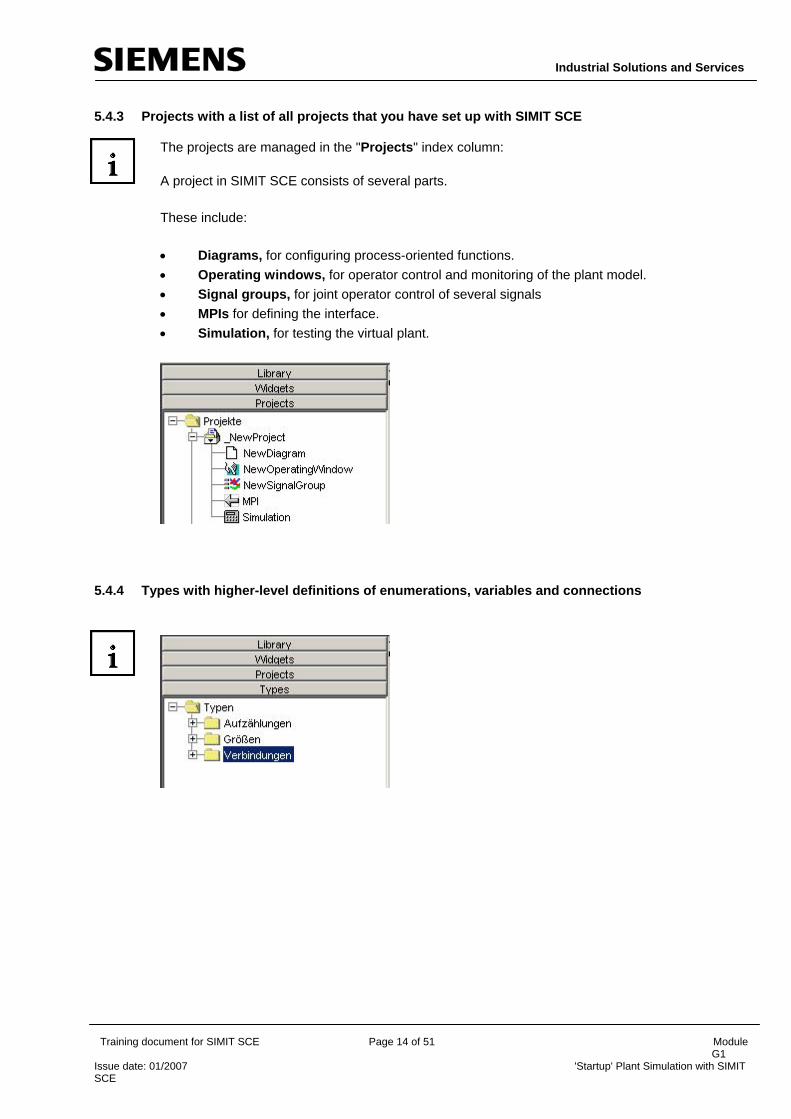
5.4.3 Projects with a list of all projects that you have set up with SIMIT SCE
The projects are managed in the "Projects" index column: A project in SIMIT SCE consists of several parts. These include: • Diagrams, for configuring process-oriented functions. • Operating windows, for operator control and monitoring of the plant model. • Signal groups, for joint operator control of several signals • MPIs for defining the interface. • Simulation, for testing the virtual plant.
5.4.4 Types with higher-level definitions of enumerations, variables and connections
G1 Issue date: 01/2007 'Startup' Plant Simulation with SIMIT SCE

Industrial Solutions and Services
Training document for SIMIT SCE Page 15 of 51 Module
6. VENTILATOR PROJECT
Task Definition:
A ventilator is started by means of an On/Off switch. In addition, a slider can be used to alter the ventilator's speed. The switch is to be operated and the speed is to be changed via a SIMIT SCE operating window. Via an interface to the SIMATIC S7 control unit, the SIMIT SCE transmits a binary and an analog input signal to the PLC. In the PLC control unit, these input signals are logically processed and routed to the binary motor output and the analog closed-loop control output for the speed of the fan impeller. SIMIT SCE records these signals via the interface and, with the help of a process-oriented diagram, simulates the rotation of the ventilator in the operating window. How to set up the "Ventilator" project 1. Start SIMIT SCE and set up a new project. 2. Start the PLCSim interface and enter I/O connections. 3. Create a new diagram and insert process-oriented functions. 4. Create a new operating window and enter and interface widgets (operator control and display elements). 5. Draw the ventilator wheel and configure the rotating movement as an animation. 6. Create a SIMIT SCE project simulation. 7. Start SIMATIC Manager and create the PLC program. 8. Start PLCSIM and load the created PLC program. 9. Start the simulation in SIMIT SCE. 10. In the operating window, you can now control and monitor the model. 11. In the diagram, you can monitor the blocks of the process-oriented functions and you can
also influence them by changing the parameters.
EIN/AUS = on/off; SOLLWERT = setpoint; drehbewegung = rotational motion; DREHZAHL = speed
G1 Issue date: 01/2007 'Startup' Plant Simulation with SIMIT SCE

Industrial Solutions and Services
Training document for SIMIT SCE Page 16 of 51 Module
6.1 Setting up a new project
Right-click on the "Projects" folder and select "New Project". Give your project the name "Ventilator". (→ Project → New Project → Name: Ventilator)
6.2 Calling the PLCSim Gateway
Right-click on the project name "Ventilator" and select PLCSim as the new gateway. (→ Ventilator → New → Gateway → PLCSim)
G1 Issue date: 01/2007 'Startup' Plant Simulation with SIMIT SCE

Industrial Solutions and Services
Training document for SIMIT SCE Page 17 of 51 Module
Expand the directory tree and select "Edit". This allows you to open the gateway for PLCSim. (→ PLCSim → Edit)
Here, basic settings can be made and the signal assignments for the binary and analog inputs and outputs can be entered. In addition, the I/O signals can be normalized in the case of the analog signal assignments. Note For better assignment of the signals, all external signals and also the associated symbolic designations in this project example are written in CAPITAL LETTERS. All internal SIMIT SCE component designations are written in lower case letters. When signals are being assigned, make sure they are written correctly, i.e. in capital letters or lower case letters. PLC address assignments must be written in CAPITAL LETTERS.
G1 Issue date: 01/2007 'Startup' Plant Simulation with SIMIT SCE

Industrial Solutions and Services
Training document for SIMIT SCE Page 18 of 51 Module
Enter symbolic designations and address assignments. Binary input
Binary output
Analog input with normalization from 0 to 100
Analog output with normalization from 20 to 100
Save symbol assignment and export as an .asc file
Select the "SIMIT" folder as the target memory and enter the file name "Ventilator".
Click on "Save" (The PLCSim gateway remains open in the background)
G1 Issue date: 01/2007 'Startup' Plant Simulation with SIMIT SCE

Industrial Solutions and Services
Training document for SIMIT SCE Page 19 of 51 Module
6.3 Setting up a diagram
Set up a new diagram in the "Ventilator" project. (→ Ventilator → New → Diagram)
Enter "Diagram" as the name and open the diagram by double-clicking on the name.
Room lights
Change the sheet size to 150 x 75 and confirm your entries with "OK". (→ Sheet → Change Size → 150x75 → OK)
G1 Issue date: 01/2007 'Startup' Plant Simulation with SIMIT SCE
Industrial Solutions and Services
Training document for SIMIT SCE Page 20 of 51 Module
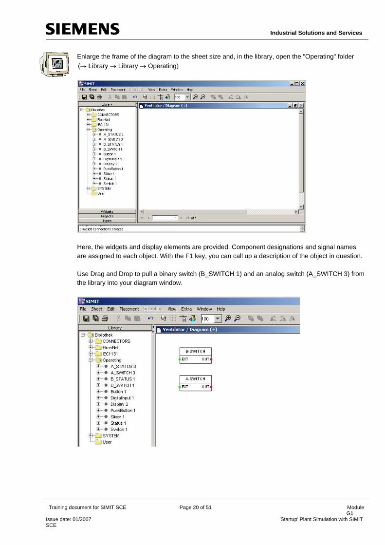
Enlarge the frame of the diagram to the sheet size and, in the library, open the "Operating" folder (→ Library → Library → Operating)
Here, the widgets and display elements are provided. Component designations and signal names are assigned to each object. With the F1 key, you can call up a description of the object in question. Use Drag and Drop to pull a binary switch (B_SWITCH 1) and an analog switch (A_SWITCH 3) from the library into your diagram window.
G1 Issue date: 01/2007 'Startup' Plant Simulation with SIMIT SCE
Industrial Solutions and Services
Training document for SIMIT SCE Page 21 of 51 Module
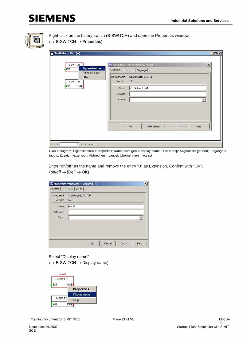
Right-click on the binary switch (B-SWITCH) and open the Properties window. (→ B-SWITCH → Properties)
Plan = diagram; Eigenschaften = properties; Name anzeigen = display name; Hilfe = help; Allgemein= general; Eingänge = inputs; Zusatz = extension; Abbrechen = cancel; Übernehmen = accept
Enter "on/off" as the name and remove the entry "3" as Extension. Confirm with "OK". (on/off → [Del] → OK)
Select "Display name" (→ B-SWITCH → Display name)
G1 Issue date: 01/2007 'Startup' Plant Simulation with SIMIT SCE

Industrial Solutions and Services
Training document for SIMIT SCE Page 22 of 51 Module
In the "Properties" box of the analog switch, enter the name "speed" and remove the entry in Extension. Confirm with OK. Select "Display name". (→ A-SWITCH → Properties).(speed → [Del] → OK) (→ A-SWITCH → Display name)
Now, a logical function has to be created for simulating the fan impeller's rotation. To this end, a value is repeatedly incremented from 0 to 360 by means of a ramp function. The counting process is to be started by means of the switched-on motor (A4.0). The counting speed is influenced by the speed output value (PQW 288). From the IEC1131\Analog\Ramps directory under Library (Bibliothek), select the "ARAMP 1" function and insert it into your diagram.
G1 Issue date: 01/2007 'Startup' Plant Simulation with SIMIT SCE

Industrial Solutions and Services
Training document for SIMIT SCE Page 23 of 51 Module
From the IEC1131\Binary directory under Library, select the "NOT 4" and "OR 5" functions and drag them into your diagram.
Enter the following names for the functions and select "Display name". ARAMP = rotating movement, OR = or, NOT = not. Make sure that the internal names for the SIMIT SCE components are written in lower case letters. Now, establish the connections of the blocks. To do this, first click on the output (red point) and then on the input (green point). The connecting lines will appear automatically.
G1 Issue date: 01/2007 'Startup' Plant Simulation with SIMIT SCE

Industrial Solutions and Services
Training document for SIMIT SCE Page 24 of 51 Module
Open your PLCSim gateway. Now, use the Drag and Drop function to pull the symbolic name or the associated address of your binary input from your PLCSim gateway to the "OUT" terminal of the binary switch (B_SWITCH).
Then, insert the remaining input and output signals into your diagram.
For the parameters of the ARAMP function, enter "360.0" in the LIMIT-UP field and "2.0" in the TIME field. Confirm with "OK".
Your diagram is now complete. Click on the button (Save All).
G1 Issue date: 01/2007 'Startup' Plant Simulation with SIMIT SCE
Industrial Solutions and Services
Training document for SIMIT SCE Page 25 of 51 Module
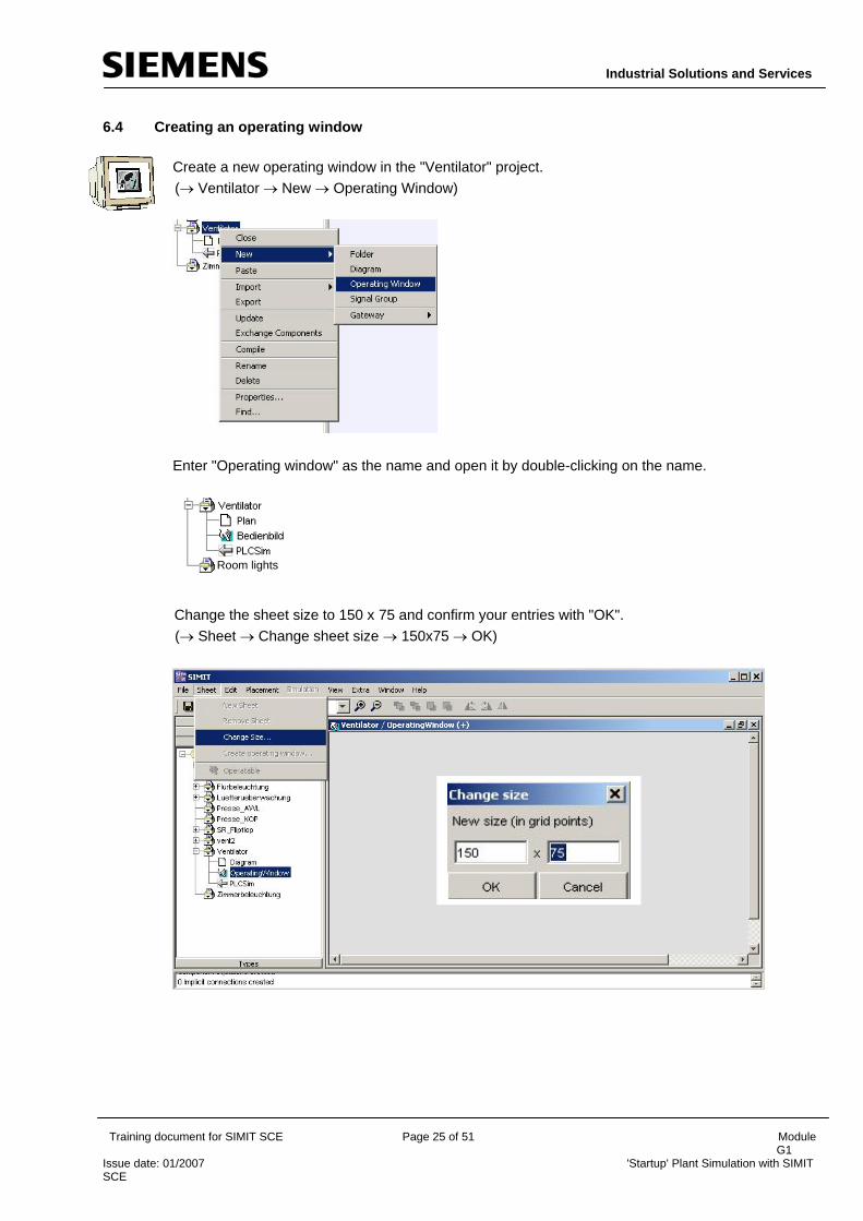
6.4 Creating an operating window
Create a new operating window in the "Ventilator" project. (→ Ventilator → New → Operating Window)
Enter "Operating window" as the name and open it by double-clicking on the name.
Room lights
Change the sheet size to 150 x 75 and confirm your entries with "OK".
(→ Sheet → Change sheet size → 150x75 → OK)
G1 Issue date: 01/2007 'Startup' Plant Simulation with SIMIT SCE

Industrial Solutions and Services
Training document for SIMIT SCE Page 26 of 51 Module
Enlarge the frame of the operating window to the sheet size and place it below the diagram.
6.4.1 Configuring widgets (display and control elements) In order to configure the operating window, components (widgets) for display and control from the widget catalog have to be inserted. Drag the change-over switch and the slider from the widget catalog in the "Operate (static)" directory and use the Drag and Drop function to place them in your operating window.
G1 Issue date: 01/2007 'Startup' Plant Simulation with SIMIT SCE

Industrial Solutions and Services
Training document for SIMIT SCE Page 27 of 51 Module
From the widget catalog under the "Display" directory, drag the binary display and the bar display to your operating window.
Now, open the Widget Properties box of the change-over switch by right-clicking on the change-over switch. Enter "on/off" as the component name and "EXT" as Signal Name Operation. In the diagram, the change-over switch is now connected to the B-SWITCH function. Confirm with "OK".
Open the Widget properties box of the slider by right-clicking on the slider. Enter "speed" as the component name and "EXT" as the Signal Name Operation. Increase the width of the slider to "150“. Confirm with "OK“.
G1 Issue date: 01/2007 'Startup' Plant Simulation with SIMIT SCE

Industrial Solutions and Services
Training document for SIMIT SCE Page 28 of 51 Module
Next, the widget properties of the binary display and the bar display are entered. Use the "not" component and the "IN" input for the binary display. For the bar display, use "rotation" for the component, and "SPEED" for the input.
Note For the widget properties, the direct addresses of the S7 control unit or the symbolic name can be also entered. Write the signal to be displayed in capital letters and make no entry for the component.
G1 Issue date: 01/2007 'Startup' Plant Simulation with SIMIT SCE

Industrial Solutions and Services
Training document for SIMIT SCE Page 29 of 51 Module
6.5 Drawing the fan impeller
Click on the button (Graphics Editor on/off). In the Graphics mode, the additional buttons
are available in the tool bar.
Click on the (rectangle) button and draw a square in your operating window.
Click on the button (Select) to change the cursor back to select mode. Right-click on the square and select "Properties".
In the "Outline" tab, the line thickness, type and color can be set. Under "Filling", a filling color or an image can be assigned.
Select blue as the filling color and click on "OK“.
Note After you have used a drawing function, always click on the button (Select) to change the cursor back to select mode.
G1 Issue date: 01/2007 'Startup' Plant Simulation with SIMIT SCE

Industrial Solutions and Services
Training document for SIMIT SCE Page 30 of 51 Module
Next, draw an ellipse with a red filling. Select "None" under Outline.
Now, make a second ellipse with the same properties. Draw a circle. In Properties under the "Outline" tab, change the line type to broken line and the line thickness to 7.
Now, use the mouse to frame the fan impeller. In the "Placement" menu, first select "Align center". Then, pull open a frame and select "Align middle". Finally, pull open a frame and select "Group". Our ventilator impeller drawing is now finished.
Click on the button to switch off the Graphics Editor.
G1 Issue date: 01/2007 'Startup' Plant Simulation with SIMIT SCE

Industrial Solutions and Services
Training document for SIMIT SCE Page 31 of 51 Module
6.5.1 Animating the fan impeller
Right-click on the fan impeller and then left-click on "Animation".
There are various types of animation you can choose from. Only one variable has to be entered in the field behind the type of animation. The values of the variable can be adapted with the Scaling button. Also, several types of animation can be combined.
In the "Rotation" field, enter the variable "rotation/PHYS“. Confirm with "OK“.
Our operating window is now finished. Click on the button (Save All).
G1 Issue date: 01/2007 'Startup' Plant Simulation with SIMIT SCE

Industrial Solutions and Services
Training document for SIMIT SCE Page 32 of 51 Module
6.6 Creating a SIMIT SCE project simulation
Our ventilator project is now completed as a plant model. Before a simulation can be carried out, the plant model has to be compiled into a simulation model; i.e. the executable simulation code. This step is performed by a code generator. The advantage to you of this SIMIT SCE procedure is that even large plant model simulations with very good performance can be calculated on a standard PC. Right-click on the project name "Ventilator" and select "Create". (→ Ventilator → Create)
Erstellen = create Confirm the message box with "OK". The compiling process is displayed at the bottom edge of the screen.
"winnt“
After code generation is completed, the simulation appears in our "Ventilator" project.
Our ventilator is now configured with SIMIT SCE.
Click on the button (Save All).
G1 Issue date: 01/2007 'Startup' Plant Simulation with SIMIT SCE
Industrial Solutions and Services
Training document for SIMIT SCE Page 33 of 51 Module
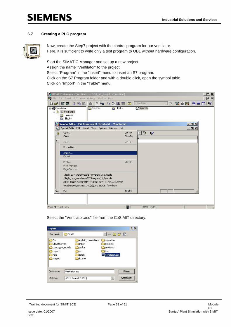
6.7 Creating a PLC program
Now, create the Step7 project with the control program for our ventilator. Here, it is sufficient to write only a test program to OB1 without hardware configuration. Start the SIMATIC Manager and set up a new project. Assign the name "Ventilator" to the project. Select "Program" in the "Insert" menu to insert an S7 program. Click on the S7 Program folder and with a double click, open the symbol table. Click on "Import" in the "Table" menu.
Select the "Ventilator.asc" file from the C:\SIMIT directory.
G1 Issue date: 01/2007 'Startup' Plant Simulation with SIMIT SCE

Industrial Solutions and Services
Training document for SIMIT SCE Page 34 of 51 Module
Confirm the following message windows with "OK". The assignments from the gateway of SIMIT SCE are now inserted in the S7 symbol table. The "syimport.txt“ information file is displayed.
Close the information file. Save and close the symbol table. Note It is possible to transfer the symbolic assignments to the gateways of SIMIT SCE by clicking on "Export" in the "Table" menu. For the gateway of SIMIT SCE, the created export file has to be simply imported.
G1 Issue date: 01/2007 'Startup' Plant Simulation with SIMIT SCE
Industrial Solutions and Services
Training document for SIMIT SCE Page 35 of 51 Module
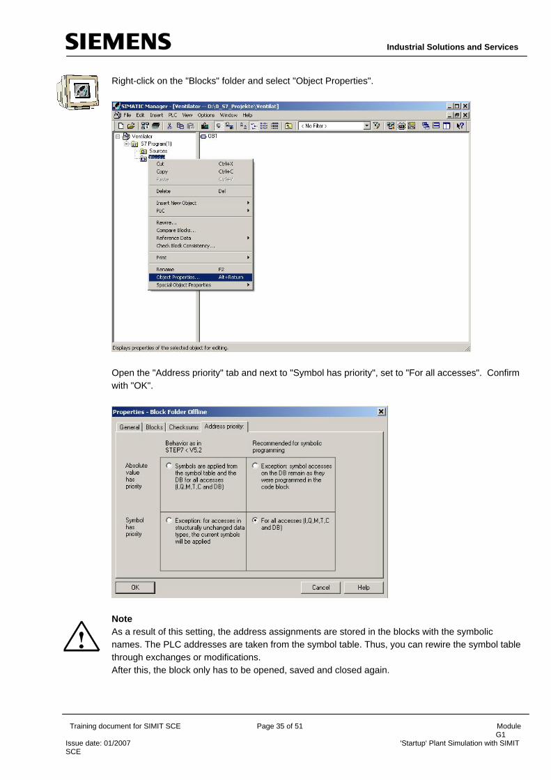
Right-click on the "Blocks" folder and select "Object Properties".
Open the "Address priority" tab and next to "Symbol has priority", set to "For all accesses". Confirm with "OK".
Note As a result of this setting, the address assignments are stored in the blocks with the symbolic names. The PLC addresses are taken from the symbol table. Thus, you can rewire the symbol table through exchanges or modifications. After this, the block only has to be opened, saved and closed again.
G1 Issue date: 01/2007 'Startup' Plant Simulation with SIMIT SCE

Industrial Solutions and Services
Training document for SIMIT SCE Page 36 of 51 Module
Enlarge the directory tree and highlight the Blocks folder. Double-click on OB1 and set the programming language to FBD. Enter the control program.
KOP/AWL/FUP = LAD/STL/FBD Click on "Save" and close the LAD/STL/FBD Editor.
G1 Issue date: 01/2007 'Startup' Plant Simulation with SIMIT SCE

Industrial Solutions and Services
Training document for SIMIT SCE Page 37 of 51 Module
6.8 Starting PLCSIM and loading the PLC program
Start PLCSIM by clicking on the button (Simulation on/off).
Insert the input and output signals in PLCSIM. Load the program into PLCSIM and start the simulator with RUN-P. Then, drag PLCSIM into the task bar. Now, change back to SIMIT SCE.
G1 Issue date: 01/2007 'Startup' Plant Simulation with SIMIT SCE

Industrial Solutions and Services
Training document for SIMIT SCE Page 38 of 51 Module
6.9 Simulation with SIMIT SCE
While the simulation is running, you can actively intervene in it by controlling the simulation process. This means you can place the simulation on hold, continue it or stop it. You can control individual components, e.g. switch a motor on and off. In addition, you can view and analyze the simulation process in various ways. Right-click on "Simulation" and select "Open".
6.9.1 Control system
The control system in SIMIT SCE ensures that a simulation model is executed in an orderly manner and in the correct time sequence. The individual parts of the model are started at the right time intervals and they are monitored to make sure they end at the specified time. The control system can be used to place the simulation on hold, to continue it in the single-step mode or to restart it. At defined points in time, the overall state of the simulation model can be recorded and stored in the database. These states can be loaded again later in order to initialize a simulation model.
The following operator actions can now be performed: • Initializing a simulation • Resetting a simulation • Starting a simulation • Setting the dynamic behavior • Placing a simulation on hold • Stopping a simulation • Simulation in single-step mode • Setting up snapshots
G1 Issue date: 01/2007 'Startup' Plant Simulation with SIMIT SCE

Industrial Solutions and Services
Training document for SIMIT SCE Page 39 of 51 Module
6.9.2 Initializing a simulation
The next step after opening a simulation is to initialize it. This is necessary for reasons internal to the system. The system triggers the initialization calculation of the individual components and sets the simulation time to zero. With the "Reset" function, initialization can be undone. Click on "Initialize"
6.9.3 Starting a simulation This control function is used to start cyclical processing of the simulation model. The simulation model cannot be started until the simulation has been opened and initialized. In order to start the initialized simulation, click on the function button (Start) in the control field.
6.9.4 Setting the dynamic behavior
SIMIT SCE provides you with several ways of setting the dynamic behavior of the simulation:
•
•
•
Realtime In this mode, the simulation time is the same as the real time. This means: after a real second, a second of simulation time has passed.
Maximum speed The model is calculated with the maximum computing power. This is helpful, for example, if you want to reach a stationary state of the model quicker.
Slow 2 – Slow 16 The module is calculated more slowly than real time by a factor of 2, 4, 8 or 16. This is helpful, for example, if you want to show very fast processes in slow motion.
When you open a simulation, the default calculating mode is "Realtime".
Note It is only possible to change between these modes during a simulation run. The dynamic behavior (real time, maximum speed or slow) depends on the calculating mode selected.
G1 Issue date: 01/2007 'Startup' Plant Simulation with SIMIT SCE

Industrial Solutions and Services
Training document for SIMIT SCE Page 40 of 51 Module
6.9.5 Placing a simulation on hold
You can place a simulation that is running on hold in order to "freeze" the current plant state, for example. During this interruption, you can continue to trigger control functions via the operating window but they do not have any effect until the simulation is started again.
6.9.6 Stopping a simulation You can stop the simulation mode by clicking on the "Close" button.
6.10 Simulation by means of the operating window Drag your PLCSIM into the operating window also, and you can now test the input and output signals of your ventilator control system in addition to its functioning.
G1 Issue date: 01/2007 'Startup' Plant Simulation with SIMIT SCE

Industrial Solutions and Services
Training document for SIMIT SCE Page 41 of 51 Module
6.11 Simulation by means of the diagram
Highlight the diagram window and click on the button (operator-controllable).
Now, the current values are visible in the diagram also. Right-clicking on the diagram opens an operating window. In it, the blocks in the diagram can be controlled or viewed. You can also alter parameters by clicking on the ">>" button.
G1 Issue date: 01/2007 'Startup' Plant Simulation with SIMIT SCE

Industrial Solutions and Services
Training document for SIMIT SCE Page 42 of 51 Module
7. CONNECTING TO THE REAL PLC
An interface connection to a real PLC can be set up by inserting the "MPI" gateway. The address indicates the MPI address of the PLC and must agree with the address set for the PLC. The slot address is the module slot of the CPU. This is always Slot 2 for the S7-300. Do not set up an MPI yet. This page is for information purposes only.
Note Since in this example, the address areas are accessed by inserted modules at the real PLC, it has to be ensured that the SIMIT SCE uses inputs and outputs that are not accessed by inserted modules, but are located in the CPU’s process image. This also applies to analog addresses. The consequence of this is that the inputs and outputs in the PLC program, in the gateway, in the diagram and in the operating window have to be adapted to the new addresses.
G1 Issue date: 01/2007 'Startup' Plant Simulation with SIMIT SCE

Industrial Solutions and Services
Training document for SIMIT SCE Page 43 of 51 Module
7.1 Changing the address in the SIMIT SCE project
In our "Ventilator" project, we have performed our programming with symbolic addressing only. It is therefore necessary to change the address at the interface and the S7 symbol table. Open the PLCSim gateway and Export the assignments as a .csv file entitled "Ventilator_PLCSim“. This causes the normalization in each case to be saved also. Select the SIMIT folder as the destination path. Exit the PLCSim gateway.
Export your "Ventilator" project. Select the SIMIT folder as the destination path.
Change the name of the project from "Ventilator" to "Ventilator_PLCSim“. Mark the "Projects" folder and import the "Ventilator" project from the SIMIT folder. Now change the project name of the imported project to "Ventilator_MPI“. Delete the PLCSim gateway in the "Ventilator_MPI“ project. Create a new gateway for MPI.
G1 Issue date: 01/2007 'Startup' Plant Simulation with SIMIT SCE

Industrial Solutions and Services
Training document for SIMIT SCE Page 44 of 51 Module
Open the "MPI“ by double-clicking on it. Import the "Ventilator_PLCSim.csv“ file from the SIMIT folder. Confirm with "Open". Now, all address assignments with normalization have been imported.
Change the input and output addresses of the MPI. I0.0 becomes I24.0, Q4.0 becomes Q24.0, PIW288 becomes IW28, PQW288 becomes QW28.
Save your MPI and export the assignments as an .asc file. Assign the file name "Ventilator_MPI. Exit the MPI.
G1 Issue date: 01/2007 'Startup' Plant Simulation with SIMIT SCE

Industrial Solutions and Services
Training document for SIMIT SCE Page 45 of 51 Module
G1 Issue date: 01/2007 'Startup' Plant Simulation with SIMIT SCE

Industrial Solutions and Services
Training document for SIMIT SCE Page 46 of 51 Module
Now, you only have to create a simulation in SIMIT SCE. Right-click on the "Ventilator_MPI“ project and select "Create".
Erstellen = create In SIMIT SCE, the project "Ventilator_MPI" is now complete.
7.2 Address changes in the Step7 program
In the Step7 project, open the symbol table. Highlight the rows and click on "Delete" in the "Edit" menu.
Import the address assignments for "Ventilator_MPI.asc“ from the SIMIT folder.
Save and close the symbol table.
G1 Issue date: 01/2007 'Startup' Plant Simulation with SIMIT SCE
Industrial Solutions and Services
Training document for SIMIT SCE Page 47 of 51 Module
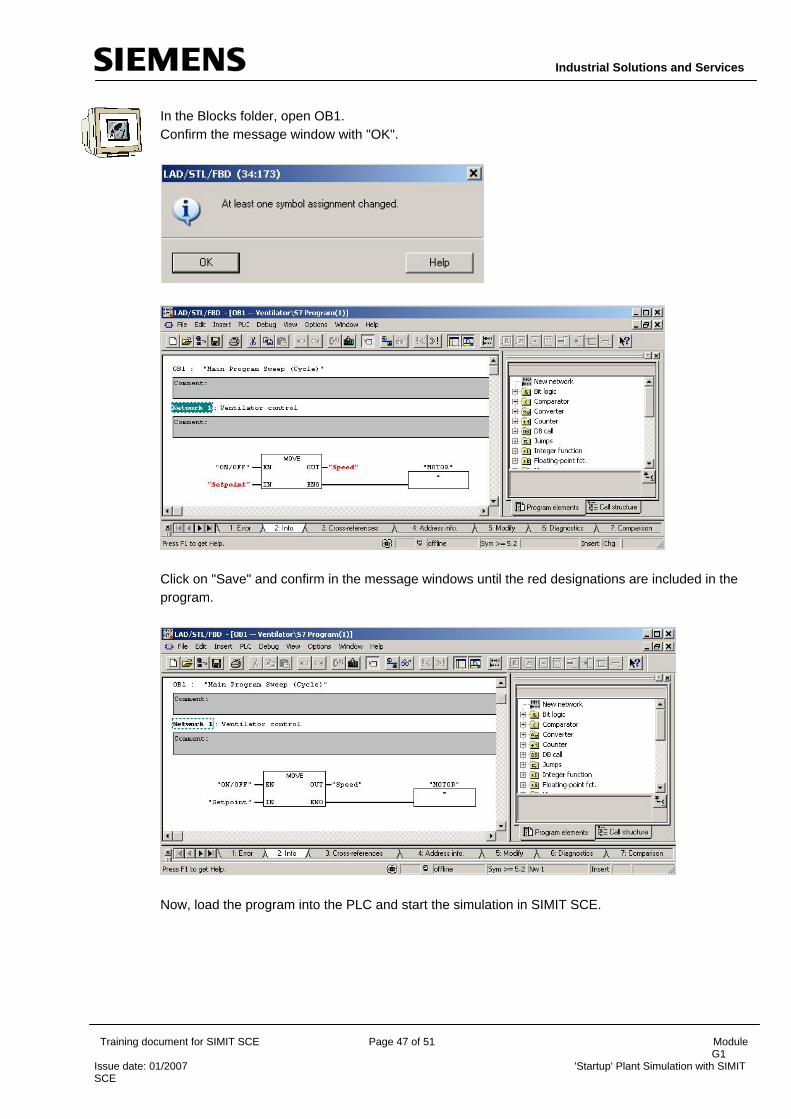
In the Blocks folder, open OB1. Confirm the message window with "OK".
Click on "Save" and confirm in the message windows until the red designations are included in the program.
Now, load the program into the PLC and start the simulation in SIMIT SCE.
G1 Issue date: 01/2007 'Startup' Plant Simulation with SIMIT SCE

Industrial Solutions and Services
Training document for SIMIT SCE Page 48 of 51 Module
8. SIGNAL GROUPS AND GRAPHS
8.1 Signal groups Signal groups allow fast and easy access to all the signals in your model. They include all I/O signals as well as the inputs, outputs, states and parameters of the model components. You can set up any number of signal groups. Signal groups are also the basis for graphs shown on the screen.
8.1.1 Creating a signal group In the "Ventilator_PLCSim“ project, create a new signal group and assign the name "Signal Group" to it. (→ Ventilator_PLCSim → New → SignalGroup → SignalGroup)
Start the Edit Mode of the signal group by double-clicking on it.
G1 Issue date: 01/2007 'Startup' Plant Simulation with SIMIT SCE

Industrial Solutions and Services
Training document for SIMIT SCE Page 49 of 51 Module
8.1.2 Editing the signal group
First, click on the "Search" button. Under Search Result, use the left-hand mouse button to select the "rotation" component with the connection name "PHYS“. Right-click on the highlighted row. Now left-click on "Select signal".
In the "Interval" column, change the high value to "360“. In the "Delta" column, change the value to "1.0“. Place a checkmark in the box for the graphic plotter. Select dark blue as the color in which the graph is to be displayed.
Note In the "Interval" column, a value normalization of 0 to 100 % is entered; i.e. if the "PHYS" ramp value is 360, a value of 100 is shown in the graph. Delta 1.0 means that the value in the graph is updated every 100 milliseconds.
G1 Issue date: 01/2007 'Startup' Plant Simulation with SIMIT SCE

Industrial Solutions and Services
Training document for SIMIT SCE Page 50 of 51 Module
Now, insert the "SETPOINT" and "SPEED" signals.
Click on the "X“ button to close the window. Click on the "Yes" button to confirm the dialog box asking you whether you want to save your entries.
8.1.3 Creating and starting a simulation Now, it is only necessary to create a simulation in SIMIT SCE. Right-click on the "Ventilator_PLCSim“ project and select "Create". Then, start the simulation by double-clicking on "Simulation".
Erstellen = Create Note: Before starting the simulation, you should open the "PLCSIM" PLC simulator and load the control program. Switch the PLC simulator to the "RUN-P" mode.
G1 Issue date: 01/2007 'Startup' Plant Simulation with SIMIT SCE

Industrial Solutions and Services
Training document for SIMIT SCE Page 51 of 51 Module
8.1.4 Opening the operating window and the signal group
Open the operating window by double-clicking on it. Double-click on the "SignalGroup" to open the Operate/Monitor mode. Here, you can control and monitor the signals in the Simulation mode. In addition, the values for the I/O signals can be set permanently.
8.2 Graph
Curve displays make to possible to graphically show the signal characteristics of connections of the components in your model with respect to their time sequence.
8.2.1 Opening a Graph Right-click on "SignalGroup" and select "Graph".
G1 Issue date: 01/2007 'Startup' Plant Simulation with SIMIT SCE

Industrial Solutions and Services
Training document for SIMIT SCE Page 52 of 51 Module
8.2.1 Graph window
The graph window contains a diagram in which the signal characteristics are shown graphically. It also contains some control elements and a table with the signals currently being shown in the graph.
Moving the inspection window With the horizontal slide control on the left-hand side and with the upper vertical slide control on the right-hand side, the inspection window to the signal characteristics can be moved. The horizontal slide control moves the inspection window between older (towards the left) and newer (towards the right) values. The vertical slide control moves the inspection window upwards or downwards. Setting the time resolution The horizontal slide control on the right-hand side can be used to alter the time resolution in which the signal characteristics are shown in the diagram. It is possible to select from 1 millisecond to 0.01, 0.1, 1, 10 seconds; 1 to 10 minutes; 1 to 10 hours and 1 to 10 days. Setting the value range The lower vertical slide control can be used to change the value range for analog signals. It is possible to select from 1% to 900%. Depending on the setting, the signal characteristics for analog signals are either stretched or compressed. Resetting the view The view can be reset to the standard settings by clicking on the "Reset" button. These settings are for a time resolution of 10 minutes and a value range of 100%. Freeze/Update view Note The signal characteristics are put on hold -that is, there is no updating- by clicking on the "Freeze" button. Updating the signal characteristics can be restarted by clicking on the "Update" button.
G1 Issue date: 01/2007 'Startup' Plant Simulation with SIMIT SCE