Training Course_SRAN6.0_MBTS(V100R004C00)_Wireless Air Interface and RF Maintenance and Testing...
55
www.huawei.com Copyright © 2010 Huawei Technologies Co., Ltd. All rights reserved. Security Level: Internal Wireless Air Interface and RF Maintenance & Testing Guide Wireless Product Service Dept. SRAN6.0 Solution
description
Huawei SRAN 6
Transcript of Training Course_SRAN6.0_MBTS(V100R004C00)_Wireless Air Interface and RF Maintenance and Testing...

www.huawei.com
Copyright © 2010 Huawei Technologies Co., Ltd. All rights reserved.
Security Level: Internal
Wireless Air Interface and RF
Maintenance & Testing Guide
Wireless Product Service Dept.
SRAN6.0 Solution

Copyright © 2010 Huawei Technologies Co., Ltd. All rights reserved. Page 2
About This Course
This course is based on the SRAN6.0 solution. Before learning
this course, you have received the training of the following
SRAN6.0 courses:
Product Overview
Operation and Maintenance

Copyright © 2010 Huawei Technologies Co., Ltd. All rights reserved. Page 3
Training Objective
After learning this course, you should be able to:
Describe the basic principles of intermodulation interference
and CDMA network interference.
Explain how to troubleshoot interference problems by using the
wireless air interface and RF maintenance and testing
functions.
Explain principles of the wireless air interface and RF
maintenance and testing functions.
Know how to use the wireless air interface and RF
maintenance and testing functions.

Copyright © 2010 Huawei Technologies Co., Ltd. All rights reserved.
Contents
Wireless Air Interface and RF Fault Detection
1. Background Information
2 Specification and Capacity
3 Offline Intermodulation Interference Test (GSM/UMTS/LTE)
4 Online Antenna Feeder PIM Test (GSM)
5 Offline Frequency Spectrum Scanning (GSM)
6 Online Frequency Spectrum Scanning (GSM)
7 Frequency Spectrum Scanning (UMTS/LTE)
8 CDMA Network Interference Detection (GSM)
9 Reference Documents & Abbreviation
Page 4

Copyright © 2010 Huawei Technologies Co., Ltd. All rights reserved.
Faults Caused by Interference
Page 5
Man-made noise is one of the main interference sources for the mobile
communication system.
Interference within or between communication equipment can be overcome by
network planning and system optimization.
User Experience
· Incoming and outgoing call failure
· Interruption
· Noise
· Mute
· Call drop
Traffic Statistics Index
· The traffic statistics show level 2 or higher level interference bands.
· The SDCCH and TCH assignment failure rates are high.
· The call drop occurs frequently, or the call drop rate is high.
· The success ratio of handovers is low.
· The rate of high level/low quality statistics is high.
Drive Test Result
· Handovers fail frequently.
· High level and low quality.
Signaling Analysis
· The BER is higher than that of other cells.

Copyright © 2010 Huawei Technologies Co., Ltd. All rights reserved.
Classification of System Interference Sources
Page 6
Hardware Fault
· TRX fault
· RF front end or divider fault
· Spuriousness and intermodulation
· Interference from antenna feeder surge protector
Inter-Network Interference
· Radar station
· Simulation BTS
· CDMA BTS
· Cordless telephone set at M900 band
· Other intra-frequency radio equipment and interference units
Intra-Network Interference
· Co-channel or adjacent-channel interference
· Repeater interference
· Intermodulation interference
The discussing scope of this document: interference types discribed in red

Copyright © 2010 Huawei Technologies Co., Ltd. All rights reserved.
Definition of Intermodulation Interference
Page 7
Four-carrier intermodulation
3rd
orde
r
5th
orde
r
7th
orde
r
Two-carrier intermodulation, power increased
3rd
orde
r
5th
orde
r
7th
orde
r
Four carrier intermodulation, power increased
3rd
orde
r
5th
orde
r
7th
orde
r
Two-carrier intermodulation
3rd
orde
r
5th
orde
r
7th
orde
r
TX
sig
nal
TX
sig
nal
TX
sig
nal
TX
sig
nal
◆Frequency spectrum analyzer test result
◆Theoretical analysis
Antenna feeder intermodulation interference: The intermodulation interference mainly comes from the antenna feeder system. When the intermodulation product of the TX signals falls into the receiving band, it will interfere with the signals in the receiving band if its amplitude is large.
Standard requirement on antenna feeder intermodulation: When the input is 2*20 W, TX signal (dBm) - Intermodulation product (dBm) > 150 dBc
Receiving band Receiving band Receiving band Receiving band

Copyright © 2010 Huawei Technologies Co., Ltd. All rights reserved.
Main Sources of Intermodulation Interference
Page 8
Intermodulation interference caused by hardware faults Out-of-band spuriousness of the TRX or power amplifier of the BTS
exceeds the limit.
The transmit and receive distance of a duplexer at the RF front end is
too small.
Intermodulation interference caused by the antenna The antenna connector is unclean. There are mechanical damage,
internal silver plating damage due to dismantling, and scrap iron in the
connector.
The antenna connector is insecurely installed or sealed.
The antenna dipoles sealed in the protective cover are eroded.
The feeder parts from the input connector to the dipoles are corroded.

Copyright © 2010 Huawei Technologies Co., Ltd. All rights reserved.
Method for Troubleshooting Intermodulation Interference
Page 9
Current Method for Troubleshooting Intermodulation Interference SRAN6.0 Improvements
· Engineers can remotely determine whether the antenna feeder intermodulation interference exists at the site, and decide whether to go to the site for handling.
· Engineers can start the spectrum scanning remotely or locally, without carrying the spectrum analyzer.
Difficulties
· Engineers cannot remotely determine whether there is antenna feeder intermodulation interference at the site. They should go to the site for troubleshooting, leading to high cost and low efficiency.
· Engineers need to carry the spectrum analyzer for the troubleshooting, but the analyzer is very expensive and requires high professional skill.
Make preparations to expose potential problems
Check whether the connectors are loose
Replace the lower jumper and redo the feeder connector
Remove the surge protector and repeater
Replace the CDMA network filter
Check whether it is BTS main device intermodulation or antenna intermodulation
Replace parts (such as antennas) on the tower
Confirm that the interference problem is solved

Copyright © 2010 Huawei Technologies Co., Ltd. All rights reserved.
Method for Troubleshooting CDMA Interference
Page 10
A CDMA BTS and an adjacent GSM BTS use adjacent bands
SRAN6.0 Improvements
· Engineers can start CDMA interference detection directly through the maintenance terminal, and obtain the test result. No professional skill is required.
Difficulties
· The uplink frequency scanning function is required to test the levels of CDMA frequencies. Engineers determine whether the CDMA interference exists based on their experience. This operation requires high professional skill.
Basic Principles of CDMA Interference
The CDMA out-of-band leakage signals fall into the GSM receiver channel
The noise level of the GSM receiver is increased
There is interference with the receiving channel of GSM/UMTS 900 MHz, deteriorating the GSM
uplink channel

Copyright © 2010 Huawei Technologies Co., Ltd. All rights reserved. Page 11
Maintenance and Testing Methods Provided by SRAN6.0Scenario Service Target Maintenance and Testing Methods Provided by SRAN6.0
Remote [Web LMT] Local [SMT]
Installation & Commissioning
of Antenna Feeders
Checking whether the project meets the requirements for PIM interference
Offline intermodulation interference test
Offline intermodulation interference test
Troubleshooting
Troubleshooting intermodulation interference
Online antenna feeder PIM test
Offline intermodulation interference test
Acquiring frequency spectrum information
Offline frequency spectrum scanning
Offline frequency spectrum scanning
Online frequency spectrum scanning -
Troubleshooting CDMA Interference
CDMA network interference detection -

Copyright © 2010 Huawei Technologies Co., Ltd. All rights reserved.
Contents
Wireless Air Interface and RF Fault Detection
1. Background Information
2 Specification and Capacity
3 Offline Intermodulation Interference Test (GSM/UMTS/LTE)
4 Online Antenna Feeder PIM Test (GSM)
5 Offline Frequency Spectrum Scanning (GSM)
6 Online Frequency Spectrum Scanning (GSM)
7 Frequency Spectrum Scanning (UMTS/LTE)
8 CDMA Network Interference Detection (GSM)
9 Reference Documents & Abbreviation
Page 12

Copyright © 2010 Huawei Technologies Co., Ltd. All rights reserved.
Specification and Capacity Applicable products
BTS3900/BTS3900A/BTS3900L/DBS3900 (GSM/UMTS/LTE) BTS3012/BTS3012II/BTS3012AE/BTS3006C/BTS3002E (GSM)
Note: For the BTS3012 series, only the new double-density DTRU supports this function. Note: For U and L, the V2/V3 platform supports offline FFT frequency spectrum scanning and
offline intermodulation interference detection. The V3 platform supports the online FFT frequency spectrum.
Matching versions BSC6900 BSC6900V900R013C00 and later M2000 iManager M2000-II V200R011C00 and later BTS BTS3900 V100R004C00 and later
License controlNone
Conflict of featuresThe RRU co-BCCH (GBFD-510104 multi-site cell) scenario does not support the wireless air interface and RF maintenance and testing function (GSM).
Page 13

Copyright © 2010 Huawei Technologies Co., Ltd. All rights reserved.
Contents
Wireless Air Interface and RF Fault Detection
1. Background Information
2 Specification and Capacity
3 Offline Intermodulation Interference Test (GSM/UMTS/LTE)
4 Online Antenna Feeder PIM Test (GSM)
5 Offline Frequency Spectrum Scanning (GSM)
6 Online Frequency Spectrum Scanning (GSM)
7 Frequency Spectrum Scanning (UMTS/LTE)
8 CDMA Network Interference Detection (GSM)
9 Reference Documents & Abbreviation
Page 14

Copyright © 2010 Huawei Technologies Co., Ltd. All rights reserved.
Offline Intermodulation Interference Test - Function Description
Basic principle (GSM) When the signals of RF frequencies f1 and f2 are sent simultaneously on the specified antenna
feeder port, check whether the levels of the 3rd order, 5th order, 7th order and higher-order intermodulation products that fall into the receiving band in the range from f1 to f2 can meet the requirements.
The counter decision thresholds of 3rd order, 5th order, and 7th order intermodulation products can be set.
The counter decision threshold of higher-order (higher than 7) intermodulation products is the same as that of the 7th order.
Basic principle (UMTS/LTE) Observe the difference between RTWP values before and during the intermodulation
interference test by controlling the transmit power of the cell, and check whether intermodulation interference exists. Significant RTWP difference indicates the existence of intermodulation interference.
The intermodulation interference is tested only when an antenna feeder port in the TRX module needs to send and receive signals. When the port just sends or receives signals, the intermodulation interference test is unnecessary and unavailable.
Page 15

Copyright © 2010 Huawei Technologies Co., Ltd. All rights reserved.
MRFU/GRFU
Offline Intermodulation Interference Test - Function Description
Applicable modules:
Page 16
TRX Module Type Port A Port B
DRRU/DRFU Supported Not supported
MRRU/GRRU Supported Supported
MRFU/GRFU Supported Not supported
The offline intermodulation interference test can be performed on only one
antenna feeder port in a single cell at one time. The antenna feeder port to be tested should be able to transmit two carriers
simultaneously.
DRRU/DRFU MRRU/GRRU

Copyright © 2010 Huawei Technologies Co., Ltd. All rights reserved. Page 17
Restrictions Carriers in other modes cannot be configured on the
corresponding TRX module of an antenna feeder port.
There is no critical alarm on the corresponding TRX module of an
antenna feeder port.
During the test, the entire cell is out of service. Before the test
starts, the BTS instructs the BSC to trigger the inter-cell service
switchover.
The high test frequency f1 and low test frequency f2 must fall into
the band that is supported by the module.
For a multi-carrier module, the bandwidth between f1 and f2 must
meet bandwidth requirements for instantaneous transmission.
Page 17
Offline Intermodulation Interference Test - Function Description
Copyright © 2010 Huawei Technologies Co., Ltd. All rights reserved.
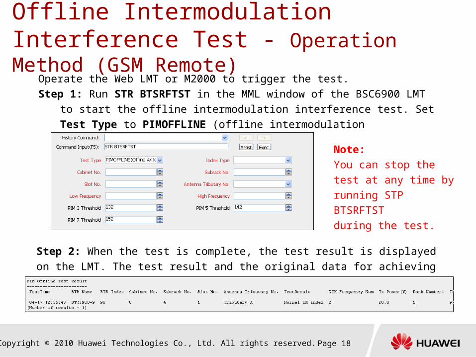
Offline Intermodulation Interference Test - Operation Method (GSM Remote)
Page 18
Operate the Web LMT or M2000 to trigger the test.
Step 1: Run STR BTSRFTST in the MML window of the BSC6900 LMT to start the
offline intermodulation interference test. Set Test Type to PIMOFFLINE (offline
intermodulation interference test).
Step 2: When the test is complete, the test result is displayed on the LMT. The test
result and the original data for achieving the result are saved in a file by the BSC.
Note:
You can stop the test at
any time by
running STP BTSRFTST
during the test.

Copyright © 2010 Huawei Technologies Co., Ltd. All rights reserved.
Offline Intermodulation Interference Test - Operation Method (UMTS Remote Terminal)
Page 19
1. Run STR RFTEST on the NodeB LMT. Set Test Type to PIMOFFLINE.
2. The offline intermodulation interference test result is displayed.

Copyright © 2010 Huawei Technologies Co., Ltd. All rights reserved.
Offline Intermodulation Interference Test - Operation Method (LTE Remote Terminal)
Page 20
1. Run STR RFTEST on the LTE LMT. Set Test Type to PIMOFFLINE.
2. The offline intermodulation interference test result is displayed.

Copyright © 2010 Huawei Technologies Co., Ltd. All rights reserved. Page 21
Step 1: Run PIM Offline Test on the SMT to start the test.
Step 2: When the test is complete, the SMT displays the test result.
Note: You can stop the test at any time by clicking Stop during the test.
Offline Intermodulation Interference Test - Operation Method (GSM Local Terminal)

Copyright © 2010 Huawei Technologies Co., Ltd. All rights reserved.
Contents
Wireless Air Interface and RF Fault Detection
1. Background Information
2 Specification and Capacity
3 Offline Intermodulation Interference Test (GSM/UMTS/LTE)
4 Online Antenna Feeder PIM Test (GSM)
5 Offline Frequency Spectrum Scanning (GSM)
6 Online Frequency Spectrum Scanning (GSM)
7 Frequency Spectrum Scanning (UMTS/LTE)
8 CDMA Network Interference Detection (GSM)
9 Reference Documents & Abbreviation
Page 22

Copyright © 2010 Huawei Technologies Co., Ltd. All rights reserved. Page 23
Online Antenna Feeder PIM Test - Function Description Basic principles
When multiple carriers are transmitted on the same antenna feeder port with antenna feeder PIM, the intermodulation product (level) is generated in the receiving band. The intermodulation product is a broadband signal.
You can check whether there is antenna feeder PIM by analyzing the uplink receiving level difference in cells during off-peak hours between scenarios with all carriers transmitting full power in the downlink and scenarios with some carriers transmitting power.
During the online antenna feeder PIM test, perform 10-second sampling of states for six times in the following sequence: power-transmitting, non-power-transmitting, power-transmitting, non-power-transmitting, power-transmitting, and non-power-transmitting, as shown in the following figure.
Page 23
Cell coverageBurst power transmitting
for 10 seconds
Cell coverageStop burst power transmitting
for 10 seconds
Cell coverageBurst power transmitting
for 10 seconds
Cell coverageBurst power transmitting
for 10 seconds
Cell coverageStop burst power transmitting for
10 seconds
Cell coverageStop burst power transmitting
for 10 seconds

Copyright © 2010 Huawei Technologies Co., Ltd. All rights reserved. Page 24Page 24
TRX Module Type Port A Port B
DRRU/DRFU Supported Not supported
MRRU/GRRU Supportedbut cannot determine whether it is port A or port B. You must use the offline intermodulation interference test function to further identify the port with intermodulation interference.
MRFU/GRFU Supported Not supported
DRRU/DRFU MRRU/GRRU MRFU/GRFU
Online Antenna Feeder PIM Test - Function Description

Copyright © 2010 Huawei Technologies Co., Ltd. All rights reserved. Page 25
Restrictions
The test should be carried out in off-peak hours. It has no adverse
impact on the cell service.
Only one online antenna feeder PIM test can be performed
simultaneously in one cell. Multiple tests can be performed
simultaneously in multiple cells at a site.
Page 25
Online Antenna Feeder PIM Test - Function Description

Copyright © 2010 Huawei Technologies Co., Ltd. All rights reserved. Page 26
Online Antenna Feeder PIM Test - Algorithm Description
Page 26
Number of groups of the valid data exceeding the Delta ≥ 2
Start
Report the existence of the PIM interference with
related data
Yes
Calculate the Delta based on the valid results of all
ARFCNs
Other ARFCNs need to be determined
Yes
No
Report the inexistence of the PIM interference with
related data
Determine the validity of ARFCN measurement
according to the ratio of full-power transmit times
Number of valid ARFCNs ≥ 1
Yes
Report the unreliability of the test result with
related data
No

Copyright © 2010 Huawei Technologies Co., Ltd. All rights reserved. Page 27
Operate the Web LMT or M2000 to trigger the test and display the result.Step 1: Run STR BTSRFTST in the MML window of the BSC6900 LMT to start the offline intermodulation interference test. Set Test Type to PIMONLINE (online antenna feeder PIM test). Note: You can stop the test at any time by running STP BTSRFTS during the test.
Step 2: The whole test lasts about 60 seconds. The BTS reports the progress every 10 seconds. When the test is complete, the test result is displayed in the MML window, and the test result and the original data for achieving the result are saved in the OMU by the BSC.
Online Antenna Feeder PIM Test - Operation Method

Copyright © 2010 Huawei Technologies Co., Ltd. All rights reserved.
Contents
Wireless Air Interface and RF Fault Detection
1. Background Information
2 Specification and Capacity
3 Offline Intermodulation Interference Test (GSM/UMTS/LTE)
4 Online Antenna Feeder PIM Test (GSM)
5 Offline Frequency Spectrum Scanning (GSM)
6 Online Frequency Spectrum Scanning (GSM)
7 Frequency Spectrum Scanning (UMTS/LTE)
8 CDMA Network Interference Detection (GSM)
9 Reference Documents & Abbreviation
Page 28

Copyright © 2010 Huawei Technologies Co., Ltd. All rights reserved. Page 29Page 29
Offline Frequency Spectrum Scanning - Feature Description Basic principles
To periodically measure the uplink receiving level of the specified
frequency in real time, you must specify the band range [f1, fk] to be
scanned and the tested carrier. The test timeslot is optional. If the
timeslot is not specified, the carrier-level scanning is performed. If the
test timeslot is specified, the channel-level scanning is performed.
Channel-level scanning: refers to the scanning of frequencies one
after another of the specified band by using the single timeslot of the
single carrier.
Carrier-level scanning: refers to the scanning of frequencies one
after another of the specified band by using all channels of the single
carrier.

Copyright © 2010 Huawei Technologies Co., Ltd. All rights reserved. Page 30
Offline Frequency Spectrum Scanning - Feature Description
Channel-level scanning
Channel-level scanning interval: The round robin to multiple frequencies in the same timeslot is
implemented.
For the channel-level scanning, the tested carrier in the cell is out of service automatically;
meanwhile, the timeslots of all carriers (including the BCCH carrier) in the cell where the tested
carrier is located are out of service automatically. The timeslot downlink of the BCCH carrier is still
available.
Page 30
Cell operating timeslot
Cell scanning timeslot

Copyright © 2010 Huawei Technologies Co., Ltd. All rights reserved.
Carrier-level scanning Carrier-level scanning interval: The round robin to multiple frequencies in all
timeslots is implemented.
For the carrier-level scanning, all non-BCCH carriers in the cell where the tested
carrier is located are out of service automatically.
Page 31Page 31
Offline Frequency Spectrum Scanning - Feature Description
Cell scanning timeslot

Copyright © 2010 Huawei Technologies Co., Ltd. All rights reserved. Page 32
Offline Frequency Spectrum Scanning - Feature Description Restrictions
Only one offline frequency spectrum scanning test can be
performed simultaneously in one cell.
On the remote (Web LMT/M2000), multiple tests can be performed
simultaneously in multiple cells at a site. In a remote test, the BTS sends information (large amount) to the
BSC through the RSL link. To ensure availability of the RSL link, the
information will be partially discarded when the link is
congested.
On the SMT, only one offline frequency spectrum scanning test
can be performed at a site.
Page 32

Copyright © 2010 Huawei Technologies Co., Ltd. All rights reserved.
Offline Frequency Spectrum Scanning - Operation Method (Remote)
Page 33
Step 1: On the Monitor tab on the BSC6900 LMT, click GSM Monitoring in the
Monitor Navigation Tree pane, and then double-click Spectrum Scan Monitoring.
The Spectrum Scan Monitoring dialog box is displayed. In the Monitor Item drop-
down list, select Off-line Spectrum Scan, and then specify relevant information as
required. Click Submit. The remote offline spectrum scanning starts.

Copyright © 2010 Huawei Technologies Co., Ltd. All rights reserved. Page 34
Offline Frequency Spectrum Scanning - Operation Method (Remote) ContinuedStep 2: After the remote offline spectrum scanning starts, the Spectrum Scan Monitoring
page is displayed on the Monitor Data tab. The maximum and average levels of main and
diversity are displayed. The reported frequency level ranges from -110 dBm to -47 dBm.

Copyright © 2010 Huawei Technologies Co., Ltd. All rights reserved. Page 35
Offline Frequency Spectrum Scanning - Operation Method (Local)
Step 1: Start the LMT for cell operations, and then double-click the Frequency Scan
command on the right. In the displayed window, specify relevant information as required,
and then click Start. The local offline spectrum scanning starts.

Copyright © 2010 Huawei Technologies Co., Ltd. All rights reserved. Page 36
Offline Frequency Spectrum Scanning - Operation Method (Local) ContinuedStep 2: After the local offline spectrum scanning starts, the scanning data is displayed in the
Frequency Scan Result Display window. The maximum and average levels of main and
diversity are displayed. The reported frequency level ranges from –110 dBm to –47 dBm.

Copyright © 2010 Huawei Technologies Co., Ltd. All rights reserved.
Contents
Wireless Air Interface and RF Fault Detection
1. Background Information
2 Specification and Capacity
3 Offline Intermodulation Interference Test (GSM/UMTS/LTE)
4 Online Antenna Feeder PIM Test (GSM)
5 Offline Frequency Spectrum Scanning (GSM)
6 Online Frequency Spectrum Scanning (GSM)
7 Frequency Spectrum Scanning (UMTS/LTE)
8 CDMA Network Interference Detection (GSM)
9 Reference Documents & Abbreviation
Page 37

Copyright © 2010 Huawei Technologies Co., Ltd. All rights reserved. Page 38
Online Frequency Spectrum Scanning - Feature Description Basic principles
When the online frequency spectrum scanning starts, the system measures the uplink receiving level of the test frequency periodically. The frequency and occasion are calculated according to the frequency hopping sequence during normal operation. The scanning result is not affected by the normal operation of other carriers in the same timeslot in the cell, as shown in the following figure.
Only the tested timeslot of tested carrier is out of service during the online frequency spectrum scanning.
Page 38
Carrier operating timeslot
Online scanning timeslot

Copyright © 2010 Huawei Technologies Co., Ltd. All rights reserved. Page 39
Online Frequency Spectrum Scanning - Feature Description To ensure the normal service, the online frequency spectrum
scanning test can be performed on only one channel in one
carrier.
The test fails if the test does not meet the following
conditions:
Only one online frequency spectrum scanning test can be performed
simultaneously on one carrier.
There is no critical alarm in the corresponding module of the carrier.
There is no LAPD alarm in the tested carrier.
The corresponding channel type of the tested timeslot must be TCHF, TCHH, or
PDCH.
Page 39

Copyright © 2010 Huawei Technologies Co., Ltd. All rights reserved. Page 40
Online Frequency Spectrum Scanning - Operation MethodStep 1: Start the BSC6900 LMT for monitor operations, and then choose Monitor >
GSM Monitor > Spectrum Scan Monitoring. The frequency spectrum time domain
scanning starts.

Copyright © 2010 Huawei Technologies Co., Ltd. All rights reserved. Page 41
Online Frequency Spectrum Scanning - Operation Method (Continued)Step 2: After the offline spectrum scanning starts, the Spectrum Scan Monitoring page is displayed on the Monitor Data tab. The maximum and average levels of main and diversity are displayed. The reported frequency level ranges from -110 dBm to -47 dBm.

Copyright © 2010 Huawei Technologies Co., Ltd. All rights reserved.
Contents
Wireless Air Interface and RF Fault Detection
1. Background Information
2 Specification and Capacity
3 Offline Intermodulation Interference Test (GSM/UMTS/LTE)
4 Online Antenna Feeder PIM Test (GSM)
5 Offline Frequency Spectrum Scanning (GSM)
6 Online Frequency Spectrum Scanning (GSM)
7 Frequency Spectrum Scanning (UMTS/LTE)
8 CDMA Network Interference Detection (GSM)
9 Reference Documents & Abbreviation
Page 42

Copyright © 2010 Huawei Technologies Co., Ltd. All rights reserved. Page 43
Frequency Spectrum Scanning - Feature Description
Scanning types Online high-precision carrier scanning
Interference around the cell frequencies in use (including a few sidebands) is checked.
Online broadband carrier scanning
Continuous spectrums (including all frequencies in use, and intervals between these frequencies) in a certain range of spectrums are checked. Its scanning precision is lower than that of the online high-precision carrier scanning.
Full-band scanning
Services must be interrupted. It can scan all frequencies in the band range supported by the RF module. Its scanning spectrum width is greater than or equal to that of the online broadband carrier scanning, and its scanning precision is lower than that of the online high-precision carrier scanning.
Page 43

Copyright © 2010 Huawei Technologies Co., Ltd. All rights reserved. Page 44
Frequency Spectrum Scanning - Feature Description
Application scenarios
Page 44
Functions Typical Application Scenarios
Adverse Impact on Services (in this mode or other modes)
Advantages Disadvantages
Online high-precision carrier scanning
There is a problem with the cell KPI. Collect information during the interference troubleshooting.
No adverse impact on local and peer services.
Services are not interrupted. The amount of data is small and the precision is high.
The states of frequencies that are not in use cannot be observed.
Online broadband carrier scanning
Use the spectrum function to check whether there is external interference when problems are found during service verification at the site in the engineering phase.
No adverse impact on local and peer services.
Services are not interrupted. Inter-frequency interference can be observed.
The precision is low.
Full-band scanning When there is a severe problem with the service KPI, the service is stopped. Collect interference information and ensure the precision.
Local and peer services are interrupted.
Wide scanning spectrum and high precision, without any adverse impact on services.
Services are interrupted (a request should be sent to the customer). The precision is low.
Note: Before the full-band scanning starts, all carriers on the RF module must be deactivated.

Copyright © 2010 Huawei Technologies Co., Ltd. All rights reserved.
Frequency Spectrum Scanning - Operation Method (UMTS)-1
Page 45
Step 1: In the Service navigation tree of the NodeB LMT, double-click FFT Frequency Scan. The FFT Frequency Scan dialog box is displayed. Set Cabinet No., Subrack No., and Slot No. to the numbers of the cabinet, subrack, and slot where the tested TRX board is located. Set Channel Type based on the application scenarios in section 2.1.2. Set Scanning Interval to the default value. Select Auto Save, and select a path for saving files, for example, D:\HW LMT\client\output.

Copyright © 2010 Huawei Technologies Co., Ltd. All rights reserved.
Frequency Spectrum Scanning - Operation Method (UMTS)-2
Page 46
Step 2: Click Yes in the Confirmation dialog box. The FFT frequency scanning starts. The
Chart tab displays the scanning result.

Copyright © 2010 Huawei Technologies Co., Ltd. All rights reserved.
Frequency Spectrum Scanning - Operation Method (LTE)
Page 47
Step: In the Service navigation tree of the NodeB LMT, double-click Spectrum Detect. In the
displayed dialog box, select the scan mode, and set Cabinet No., Subrack No., and Slot No. to
the numbers of the cabinet, subrack, and slot where the tested TRX board is located. Set other
parameters to default values. Click Submit.

Copyright © 2010 Huawei Technologies Co., Ltd. All rights reserved.
Contents
Wireless Air Interface and RF Fault Detection
1. Background Information
2 Specification and Capacity
3 Offline Intermodulation Interference Test (GSM/UMTS/LTE)
4 Online Antenna Feeder PIM Test (GSM)
5 Offline Frequency Spectrum Scanning (GSM)
6 Online Frequency Spectrum Scanning (GSM)
7 Frequency Spectrum Scanning (UMTS/LTE)
8 CDMA Network Interference Detection (GSM)
9 Reference Documents & Abbreviation
Page 48

Copyright © 2010 Huawei Technologies Co., Ltd. All rights reserved. Page 49
CDMA Network Interference Detection - Feature Description Basic principles
The CDMA interference to the GSM uplink can be decreased by modifying the
diminution factor of the tower mounted amplifier or adjustable attenuator in
other receiving channels, which is called CDMA interference suppression.
Delta: refers to the uplink receiving level average difference of the operating
frequencies in the idle channels when the CDMA interference suppression is
performed and not performed.
The BTS determines whether the CDMA network interference occurs by
comparing the Delta and the decision threshold.
Operating frequencies for comparison: If the number of operating frequencies
is greater than 8, 8 operating frequencies most adjacent to the CDMA band are
used for the decision. Otherwise, all configured operating frequencies are
used. If an operating frequency Delta exceeds the decision threshold, the
CDMA network intermodulation exists. Otherwise, the CDMA network
intermodulation does not exist.
Page 49

Copyright © 2010 Huawei Technologies Co., Ltd. All rights reserved. Page 50
CDMA Network Interference Detection - Feature Description Restrictions
Only one CDMA network interference detection can be performed
simultaneously in one cell. Multiple tests can be performed
simultaneously in multiple cells at a site.
During the test, the diminution factor of the tower mounted amplifier
and adjustable attenuator in other receiving channels will be modified,
which will temporarily reduce the capability of resisting CDMA network
interference. However, the adverse impact on the service is low.
Page 50

Copyright © 2010 Huawei Technologies Co., Ltd. All rights reserved. Page 51
Step 1: Run STR BTSRFTST in the MML window of the BSC6900 LMT to start the
CDMA network interference detection.
Note: You can stop the test at any time by running STP BTSRFTS during the test.
CDMA Network Interference Detection - Operation Method
Step 2: When the test is complete, the test result is displayed in the MML
window, and the test result and the original data for achieving the result are
saved in the OMU by the BSC for further analysis.

Copyright © 2010 Huawei Technologies Co., Ltd. All rights reserved.
Contents
Wireless Air Interface and RF Fault Detection
1. Background Information
2 Specification and Capacity
3 Offline Intermodulation Interference Test (GSM/UMTS/LTE)
4 Online Antenna Feeder PIM Test (GSM)
5 Offline Frequency Spectrum Scanning (GSM)
6 Online Frequency Spectrum Scanning (GSM)
7 Frequency Spectrum Scanning (UMTS/LTE)
8 CDMA Network Interference Detection (GSM)
9 Reference Documents & Abbreviation
Page 52

Copyright © 2010 Huawei Technologies Co., Ltd. All rights reserved. Page 53
Reference Documents
1. "Wireless Air Interface and RF Maintenance and Testing Guide" in
Equipment Deployment Guide_GBSS13.0_BTS3900 Series Macro
Base Stations
2. GSM BSS Network Performance KPI (Interference Problem)
Optimization Manual
3. SingleRAN6.0 MBTS Equipment Deployment Guide Subject 14 -
RF Detection Capability Enhancement

Copyright © 2010 Huawei Technologies Co., Ltd. All rights reserved.
Abbreviation
Page 54
PIM: Passive Intermodulation

Thank youwww.huawei.com