Training Booklet Builder and technicians...Pumping test . 13 . Building a tank . 14 . Borehole . 17...
32
Inter Aide Hygiene, Sanitation & Water Supply Project Training InterAide Technical Part Hygiene Sanitation and Water Supply Projects in Malawi Training Booklet Builder and technicians Updated on 25 th November 2002 BenoîtMichaux
Transcript of Training Booklet Builder and technicians...Pumping test . 13 . Building a tank . 14 . Borehole . 17...

Inter Aide Hygiene, Sanitation
& Water Supply Project
Training Inter Aide Technical Part Hygiene Sanitation and Water Supply Projects in Malawi
Training Booklet Builder and technicians
Updated on 25th November 2002 Benoît Michaux

Inter Aide
Page 2
Index 1. Index
Materials 3
Bricks 3
Concrete blocks 3
Sand and Stone 4
Concrete 5
Iron and Metal 7
Resistance Theory 8
Load and moments 8
Reinforced concrete 10
Shallow well 12
Siting 12
Frame 13
Excavation 13
Pumping test 13
Building a tank 14
Borehole 17
Siting 17
Gravel Pack 20
Development 21
Pumping Test 24
Civil Work 29
Introduction
This handbook was used as background document for a training of builder supervisors in Malawi. Their past assets in the field of construction are limited in the theoretical field. On the other hand they profit from a significant experience and skill. We tried to describe the matters from the practical point of view. However, it proved significant to introduce some theoretical concepts. The description of those concepts doesn’t enter into details and wants to be concise. The use of this handbook requires a training support and targets a precise public.

Inter Aide
Page 3
Materials 1. Bricks.
1.1. Baked Bricks All phases are important : Collection of materials, Moulding, Burning and also testing.
- Materials Three types of clay can be found in the field (Illites (mica); Kaolinite and Montmotillonite). Among these three types, one of them, the Montmorillonite, shall not be used as building and construction material. The Montmorillonite swells when mixed with water. (It is this kind of clay that is responsible for the sinking places in rainy season).
How to recognize this kind of clay: it is not a question of colour (the colour comes from the metallic ions contained in the clay): we should do the test of adding water to this kind of clay. If it is montmorillonite; the clay will swell and when it starts to dry, some big crack will appear on it.
The sand: see notes page 4. Small quarry stones can be added (< 0,7cm ∅). The Sand Part has to be < than 1/3.
- Mould The moulds can be made in wood or in steel. It must be wet before pouring the clay. The mix must be homogenous. When the compaction is done in the mould, the first drying will be done on a perfectly horizontal area. The area is prepared before moulding the bricks. This is important to avoid having bricks of different sizes.
- Baking The first requirement is to bake the bricks evenly. The second requirement to be respected is a good isolation of the brick oven with 6 cm of mud, otherwise the peripheral bricks will be under baked. Max distance between “hover” and last bricks is < than 1 m.
- Final test before using: Two tests are required before using the bricks: the first test is to knock one brick on another and listen to the sound made. If the sound is clear, it means the bricks were correctly baked. If the bricks break or if the sound is heavy, it means that it was not correctly baked or that the mixing was not well made.
The second test is to put one or two bricks in a bucket of water during 24 hours. After 24 hours, if the bricks crumble, it means that the materials were not correctly chosen or that it was not baked enough.
1.2. Concrete Bricks or blocks Two types of mix are proposed here.
Mixing for moulding bricks and elements (Volume) Volume Quarry stones
< 1cm ∅ Sand Cement Water
2 2 - 3 1 0,5 4 - 5 1 0,5
The sieving - straining for sand and quarry stones is very important.
The mix will be completed and hardly moved (mixed) before and after putting the water. The proportion of water has to be respected.

Inter Aide
Page 4
Compaction Annexe 1
Four types of compaction can be expected.
Hammer Compaction
Increase the compaction by 10%
Compaction with Iron Bar
Increase the compaction by 25%
Shock waving Mould
Increase the compaction by 35%
Electrical waving compressor. Increase the compaction by 40%
- Some rules are required for the concrete moulded bricks. - The mix should not dry too fast. A wet environment (more than 65 –70 % of humidity) is required; this can be achieved by covering with plastic paper or other types of covers. - Before aligning the elements to dry, the surface has to be wet. - The surface must be horizontal.
1.3. Sand and quarry stones. The sand has to free of clay, alluvium and organic part (grass, wood, roots…)
Sieving for Sand Sieving
> 0.5cm ∅ Kept part Sieving
< 0.05cm ∅ Gravel, stones and organic Sand "fines" + clay +alluvium and
silt Rejected Accepted Rejected
In the same way Cleaning of sand could be used in order to clear water. However, that requires a significant quantity of water. Clay being detrimental to the quality of concrete by limiting its resistance and causing it to fissure, sand should be sifted when dry to avoid clay adhering to it. The following test can be interesting: Put the sand in a little transparent container (half of the volume), mix it with water and agitate it (look for the result: if the water is clear, there were no clay).

Inter Aide
Page 5
Compression Capacity for concrete
0
5
10
15
20
25
30
35
0 4 8 12 16 20 24 28 32 36 40 44 48 52
days
N/m
m²
For the stones and quarry stones, only one kind of rock is prohibited : it's alkali-silicate rocks
Alkali-silica reactivity is an expansive reaction between reactive forms of silica in aggregates and potassium and sodium alkalis. External sources of alkali from soil can also contribute to reactivity. The reaction forms an alkali-silica gel that swells as it draws water from the surrounding cement paste, thereby inducing pressure, expansion and cracking of the aggregate and surrounding paste. This often results in map-pattern cracks, sometimes referred to as alligator pattern cracking. ASR can be avoided through 1) proper aggregate selection, 2) use of blended cements, 3) use of proper pozzolanic materials and 4) contaminant-free mixing water.
Caution: the storage is important: if the sand is stored (without protection) during more than 1 month, it has to be sifted again.
2. Concrete. Although the terms cement and concrete often are used interchangeably, cement is actually an ingredient of concrete. Concrete is basically a mixture of aggregates and paste. The aggregates are sand and gravel or crushed stone; the paste is water and Portland cement. Concrete gets stronger as it gets older. Portland cement is not a brand name, but the generic term for the type of cement used in almost all concrete (just as stainless is a type of steel and sterling a type of silver). Cement comprises from 10 to 25 percent of the concrete mix, by volume. Through a process called hydration, the cement and water harden and bind the aggregates into a rocklike mass. This hardening process continues for years meaning that concrete gets stronger as it gets older. This graphic is showing the resistance of compression evolution for concrete. We
commonly use a Cement 30. It means the concrete could resist to 30 N/mm² after 28 days (See Compressive Test). So, there is no such thing as a cement sidewalk, or a cement mixer; the proper terms are concrete sidewalk and concrete mixer.

Inter Aide
Page 6 Materials that contain appropriate amounts of
calcium compounds, silica, alumina and iron oxide are crushed and screened and placed in a rotating cement kiln. Ingredients used in this process are typically materials such as limestone, marl, shale, iron ore, clay, and fly ash. The kiln resembles a large horizontal pipe with a diameter of 10 to 15 feet (3 to 4.1 meters) and a length of 300 feet (90 meters) or more. One end is raised slightly. The raw mix is placed in the high end and as the kiln rotates the materials move slowly toward the lower end. Flame jets are at the lower end and all the materials in the kiln are heated to high temperatures that range between 2700 and 3000 Fahrenheit (1480 and 1650 Celsius). This high heat drives off, or calcines, the chemically combined water and carbon dioxide from the raw materials and forms new compounds (tricalcium silicate, dicalcium silicate, tricalcium aluminate and tetracalcium aluminoferrite). For each ton of material that goes into the feed end of the kiln, two thirds of a ton the comes out the discharge end, called clinker. This clinker is in the form of marble sized pellets. The clinker is very finely ground to produce portland cement. A small amount of gypsum is added during the grinding process to control the cement's set or rate of hardening. (CBR Lixhe Documentation, 1996)
Mixing
Concrete must be mixed thoroughly to yield the strongest product. A. Mixing with a machine
B.
: Add about 10% of the water in the drum. Then gradually add water uniformly with the dry material leaving another 10% to be added after the dry materials are in the drum. Allow 5 or 6 minutes after all the materials are in the drum. Mixing by hand
1. Spread the sand evenly over the mixed area
: the mixing area must be clean and water-tight. Use the following procedure:
2. Spread the cement evenly over the sand and combine until the colour is uniform 3. Spread the mixture out evenly and add the gravel on it and mix it thoroughly again. All
dry materials should be thoroughly mixed before water is added. 4. Shape the dry mix into a pile and form a hollow bowl in the centre. Pour some of the
water into the bowl, gradually mixing in the dry mixture until all the water is absorbed. Re-form the pile and bowl, add and mix more water. Repeat until the concrete is ready to pour.
A workable mix should be smooth and plastic (not wet and runny or dry and crumbly). If the mix is too wet, add small amounts of sand and gravel (in proportions) until the mix is workable. If the mix is too stiff, add small amounts of water and cement until the mix is workable. Note the amounts of the materials added for future batches.
Mixing for Cement ( Part in volume) Use Rocks Gravel or
Quarry stones
Sand Cement Water Slump Test (cm)
Foundation Yes 2 4 1 0.6 12 Floor Yes 3 3 1 0.6 14 Plastering 0 0 3 1 0.6 11 Brick mortar 0 0 3 1 0.6 12 Dry Concrete (thin concrete)
0 1 4 1 0.45 – 0.55 15
The minimum value for the Eau/Cement ratio is 0.35 and the maximum value is 0.8 (volumetric ratio). In fact only ratio 0.28 is required for the chemical reaction but evaporation should be considered
Mixing for Cement ( Part in weight)

Inter Aide
Page 7 We should first consider the volumic weight before to any mixing
part.
Water 1 Kg/l Sand 2,65 kg/l Rocks 2,65 kg/l Cement 2,9 to 3,1 kg/l
A sample could illustrate the mix parts for a total of around 1 cubic meter.
Material Volume (litre)
Weight (Kg)
Rocks 516 l 1367 Kg Sand 153 l 406 Kg Cement 119 l 370 Kg Water 200 l 200 Kg Total 998 l 2343 Kg
We can frequently see on the field that Masonry mortar is periodically diluted. The implementation of Masonry mortar ask an use period. And community member or builder add frequently water within the mortar. Two problems appear:
- The chemical reaction already started between Water and cement. the addition of this Water will cause cracks because of empty volumes;
- Dilution also will clean the mixture and will decrease the Cement / Sand ratio. This ration can pass from 1/3 to less than 1/6.
To avoid a fast chemical reaction between cement and water, we could add sugar but the percentage of sugar has to be smaller than 1,2 % of the cement part ( and >0,3 %)
Test for concrete
a. Slump Test
This test will be done from our proper rules. It is taken from the conical test which is an international test.
Materials needed: take a part of casing pipe (11cm ∅) and 20 cm high.
After the mixing is completed, the builder has to fill the pipe with the fresh concrete without any compaction. The test consists in moving out the pipe and checking the remaining height of the concrete. It has to be done just after the mixing.
b. Compressive Test
Normally the resistance of a normal concrete (2-3-1) is written for each quality of cement and is written on the cement bag. The most common cement (and this is what we find in Malawi) has a resistance of about 30 N / mm². It means that after 28 days, each squared millimetre will resist to about 3 Kg.
For our test, we have to build a cube (5 cm x 5 cm x 5 cm) and let it dry during only 7 days (one week) to reduce the time of decision. So normally the cube must resist to 50 mm x 50 mm x 10 N (because in 7 days the strength is not full) x 0,5 due to smallness . It means that this cube has to resist almost to 1,25 tons (consider 1 ton). The test will be to charge the cube.
Checking the right proportions
The question is: "what happens when the proportions are not respected?".

Inter Aide
Page 8
what happens when the proportions are not respected ? Physical aspect Consequences
Too much water Only 0.27 is needed for the fraction (Water on Cement). If there is too much water (more than 0.6), little empty spaces will appear within the concrete.
Another phenomena could appear (segregation) during the drying: the stones and gravel will go down and water and cement staying up
Cracks will appear soon and erosion. Too much water is a dangerous mistake.
Not enough water Less than 0.27 for the fraction (water on cement): somewhere the reaction will not be complete.
The concrete is not so strong but the strength could come later with external water.
Too Much Sand Empty spaces could appear because there are not enough thinner particles.
The compressive capacities are ok but not the traction capacities and others characteristics.
Not enough sand The exothermically chemical reaction will be to fast
Small cracks will appear. Some kind of fragility. Like when the cement is drying too fast.
Too Much cement Same as above Same as above
Curing
After the forms are filled, the concrete must be cured until it reaches the required strength. Curing involves keeping the concrete damp so that the chemical reaction that causes the concrete to harden will continue as long as necessary. When the concrete dries, the chemical hardening ceases and cannot be reactivated. The best way to keep the concrete wet in very hot countries is to plug the drainage channel (soak-away pit) and then concrete pad and drainage channel with water. Water could be sprayed to keep the concrete covered. Additional rules
- We must never add water if the cement begins to dry. There are no solution one the mixing is made and the chemical reaction has started. The only solution is: correct preparation and organisation.
- The common surfaces have to be wet and cleaned before applying cement mortar or plastering.
- The drying has to be slow to avoid cracks (cover + good organisation)
3. Iron, metals and Steel. The corrosion is the main problem that can appear on the metal. There are two kinds of corrosion but we will first see what happens when corrosion appears. Metal is made of metal atoms (Fe, Zn, Au, Cu, Mn,…) or a combination of them. The corrosion is the oxydation of the metal. The atom Fe → Fe++ + 2 e-
Like that the ion is going out from the structure. At the same time the phenomenon of reduction happens. Zn+ + e- →Zn This could appear as a

Inter Aide
Page 9 reinforcement but the adding isn't done structurally. The
same phenomenon of oxydation-reduction happens in batteries or for galvanisation. As we said, there are two kind of corrosion:
- The topping corrosion is less dangerous and takes a long time to transform the structure radically. It's when there are not two metal located in contact. For example, this kind of corrosion appears on the iron bars used with concrete when there are stocked. The corrosion is homogeneous only because there is very little difference of carbon concentration in the steel. We can also observe that the first lay of corrosion is used in the beginning as a protection lay.
- The digging corrosion is more dangerous. It happens when there are two different metal in contact or a big difference of carbon concentration or other chemical difference. It's happen when we have two pipes (copper and steel) in contact (as well a welding is done with a different Carbon concentration) Or it’s appearing also when a bolt is directly in contact with metal…
It's possible to protect the metal by: - painting it with a special paint or almost 3mm of oil paint - use Galvanisation - grease or oiling - link with copper wire (where the corrosion is coming before) - …
Resistance Theory
THEORY ABOUT LOADS AND MOMENTS. Every times there is a load, there is a reaction from the materials (ground or other) with the same intensity but in opposite direction. The reaction has the same intensity than the action, otherwise it causes movement. The limits for traction and compression are as follows:
Materials Wood (Normal)
Normal Concrete
Good –strong concrete
Iron Poor (soft)
Iron Middle
Iron Strong
Compression 10 – 20 N/mm²
20 N/mm² 50 N/mm² 200 N/mm²
600 N/mm²
2000 N/mm²
Traction 15/25 N/mm²
2 N/mm² 10 N/mm² 200 N/mm²
600 N/mm²
2000 N/mm²
Where 1 N / mm² is 1 Newton per square millimetre. And 1 Kg is 9,81 Newton (10 N). It means that for a cube of 10 cm * 10 cm on surface, it has to resist to at least up to 20 tons for a normal concrete after 28 days. We can note the poor resistance of concrete to traction comparing to its resistance to compression. It is important to keep this in mind when dealing with reinforced concrete.

Inter Aide
Page 10
When the reaction and the first efforts are under the same line we have only compression or traction. But if the action and the reaction are not on the same line another component appears. It is called the Moment.
By example, if we try to open a door, we will place one compression (or traction on the handle). What happens? First there is a reaction on the hinge and because of the permitted movement in the hinge the door opens.
Imagine now that we avoid any movement by blocking the hinge. The “hinge” point has now to do a rotary reaction of the same intensity than the action.
It appears one value called Moment defined by the action and the distance between action and reaction. The reaction moment is created as an effort de reaction. The moment is valid and different at any point on the beam of bar (here, the door) The “moment” on point R (where the reaction is applied) is M=P.d (true if there is no reaction on the point P) Consider now a beam: On each feet of the beam, appear reactions and along a moment (depending from the place) is seen. The principal load is not on the same line than the reactions.
Let’s consider now the section of the beam. Appear on it a moment M and practically on this section this moment could be describe by to yield: a traction and a compression. So in this description of a beam, the traction is on the bottom and compression is on the top of the section. To calculate the reaction in the structure, we start with the rules of equity, that is:
- The sum of the vertical loads and reactions equals zero (the sign is coming from the direction of the load). P-R1-R2=0.
- The sum of the horizontal loads and reactions equals zero (the sign is coming from the direction of the load). In this sample: 0=0.
- The sum of the moment (applied and reaction) on each point equals zero. Moment on R1: MR1 + P . distance to P-R2 . length of the beam = 0. On the end of the beam, the rotation is permitted (it is not blocked by a wall or something else). So MR1=0 but only on the point R1.
Characteristics influencing the resistance
- Materials Many different materials are used but these are the three most commonly used: 1°: steel is very strong but expensive and heavy; 2°: wood is light, but the characteristics are changing along the years; 3°: concrete: easy to work with. But the problem of the concrete is the very poor traction capacity. We therefore consider that concrete cannot resist to traction. It needs an additional strength: this is why it is reinforced with iron bars.

Inter Aide
Page 11 - The length
The length of the beam is very important. The longer the beam is, the higher are the solicitations. The traction and compression should be increased. - The Weight or other solicitations The higher the weight or solicitations are, the higher the traction and compression will be. The place where the weight is applied is also important. - The Beam section The Beam section is important. If we increase the section of the beam we increase in the same way its capacity to give reaction against those solicitations. - The orientation of the section. The most important thing is the orientation of the section. For a same section the capacity of reaction could be different. This is coming from the distance between Traction and Compression. In this picture the second beam will be more efficient than the first one.
WHAT ABOUT REINFORCED CONCRETE? One of the characteristics of concrete is its poor resistance to traction. To avoid any crack and to increase the resistance of a beam, we can put iron bars in the traction side. For a single beam, like in this picture, the traction side will be at the bottom of the beam; this is where the iron bar shall be
put. Consider a flat rectangular roof. When a load weighs on it, the roof will be curved. If the curve is too strong, the roof will crack. For a rectangular structure set on a rectangular wall (l x L; with L>l) as on the picture below, the acceptable curve has to be the one for l. So to strengthen efficiently the concrete in this roof, we have to set iron bars along the l direction
and not along the longer one. We place iron bars in the longer section as well, so as to maintain the other iron bars (so we need smaller diameter). The iron bars are wired or welded together to avoid movement during concrete flowing.
For a square or a circle, the L direction is considered as the l one.

Inter Aide
Page 12
Some rules: - An iron bar should not be cut in the middle of a
length. If it has to be done, the two irons bars must overlap each other by 50 cm
- If there is hole on your roof. The cut iron bars have to take seat on other ones.
- If the roof has two holes you have to choose the predominant bars.
Choosing the size of the iron bars This following grid has to be used with care. If the structure is loaded with something else than normal load (per example where people will frequently walk , or car,..) the calculation has to be given to a skilled engineer.
Distance between bars Diameter for the iron bars Concrete
thickness Length l 4 mm ∅ 6 mm ∅ 8 mm ∅ 10 mm ∅ 12 mm ∅
1m 15 cm 25 cm 4 cm 2m 15 cm 20 cm 8 cm 3m 10 cm 20 cm 12 cm 4m 10 cm 20 cm 15cm
For the other direction, the diameter could be the under diameter (under) the predominant one and double distance between the bars. All the time almost 1,5 to 2 cm of concrete have to cover the iron bars to avoid any future corrosion. The belt When a wall is being built and special attention has to be given to avoid cracks, a belt can be built with reinforced concrete: the recovering would also be 50 cm if it is done for a building such as a house. It has to be between 200 cm to 250 cm from the ground. For a tank it can be 1 to 120 cm For water tank floor: we do not know exactly in which direction the curb will be. So the iron bars will be in the middle of the section and special care is given to the corner. The dimensions of an efficient water point are: a cylinder the height of which equals the diameter. For the design, see the Spring Catchment’s Handbook

Inter Aide
Page 13
For the column or pillar, some load could be horizontal and iron bars could be needed. The best way is to put three iron bars (even 6 mm, the heaviest weight is
the compression and the horizontal one is normally) as the section picture. The foot of a pillar is also fragile so the link with the foundation has to be made in both directions.
Shallow Wells
SITING. Where to locate the shallow well? A lot of tools can be used. The first requirement is to involve the community in this decision: the following tools can help to choose the best place:
Drawing a community Map Previous unprotected wells and availability. Trees (blue gum, bamboos, banana trees) are good
indicators for the water. Topological data (surfaces, around rocks, over flowing) Dambo and type of shrub. Gullies and other risks The community ‘s experience Soil textures and other. Resistivity method; if available.
The final quality of water taken from a well will partly depend on how close it is to potential sources of contamination. The well site should be placed on raised ground and at least 50 meters away from latrines, cattle kraals and rubbish pits or other hollows in the ground. This ensures that contaminated water will not drain through the ground into the well. It is important that the well is always up hill of a latrine or a cattle kraal. Obviously the site should be as close as possible to where people live and convenient for them. The community in consultation should choose the precise site with the Health Assistant, and with the help of the local water diviner, who may be able to locate a site with a high yielding aquifer. The diviner will look at the lie of the land, make a note of the soil type and catchment’s area. His general knowledge of the land coupled with the movement of the divining stick may locate a good site for water. If a band of capillaries or under ground streams is found, the well will have a good yield compared with one that penetrates clay.

Inter Aide
Page 14
10006060830
∗∗∗
∗PopulationTotal
TIME FRAME.
Janu
ary
Febr
uary
Mar
ch
April
May
June
July
Augu
st
Sept
embe
r
Oct
ober
Nov
embe
r
Dec
embe
r
Village 1st meetings
Digging Pumping Test Tank Building Civil Work Pump Installation
EXCAVATIONS Existing wells:
If an existing well has been chosen for upgrading, it should be deepened as far as possible and the sides should be cut straight. Clearly this is best achieved during the time of the year when the water table is at its lowest, mainly in October and November. A well-experienced digger and his team should be chosen to excavate the final few meters of a existing well.
New well.
After a suitable site has been chosen, a 2-meter diameter ring is marked on the ground to show where the well should be dug. On the last day, the final effort must be made to penetrate as far as possible into the water. Normally it is possible to penetrate two or three meters into the aquifer. If there is a risk of collapse of the well, the well should be built as soon as possible. That means before one week after the digging.
PUMPING TEST There are a lot of different methods to insure the adequate quantity of water within the well.
1° The civil work and building represent a lot of expenses and will represent most of the investment. 2° The availability of water of the shallow well is one of the first factor influencing the villagers’ motivation. 3° Some shallow well could be calculated to have the water during the rainy season (and up to July) so as to avoid the problem of Cholera and most of the diseases during the dangerous period of the year. Nevertheless if we could go on with this idea the problem could also come with the worn out of the pump materials.
For those reasons it is crucial to make sure of the flow rate (yield) of the well. 1. Objectives, hypotheses and rules. It is necessary to measure flow before the construction of the well begins. If the well does not give enough water, it should be dug deeper or another location must be chosen if it is not possible to dig more.
The pit has to be straight and vertical. We have to know the population of the village and the villagers’ habits. The calculation must be easy and usable. One person uses about 30 litres a day. So for the village, the total water needed (in litres) is: Total population * 30 We consider that the pumping time is reduced to 8 hours. So the consumption flow is ( in m3/s).

Inter Aide
Page 15
thD∗∗∗Π
4%80*2
3041000606088.0*2
∗∗∗∗∗∗∗∗Π
≤PopulationTotal
hDt
PopulationTotalhDt ∗∗
<2603,0
Taking into account that the flow in the well decreases with the depth of water and considering that what we are
looking for is the volume of water for consumption (not the water speed) we consider 80% of the water high. The time to have the fully water column is too long and 80% of the water depth is corresponding to lees than 25% for time. If we calculate the average yield we should have:
Where t is the time
calculated. The fraction is written in (m3/s) If we compare both fractions: (t in second) It means when we are calculating the values: Where D is the diameter written in centimetre
And h is the total depth of water table written in centimetre. With D; H in cm
2. Method. 1° wait for 1 to 2 days without pumping from the well. 2° measure the water depth (h in centimetre). 3° measure the diameter of the well (D in centimetre). 4° pump all the water form the pit and send it more than 15 meters away from the well. 5° measure the time taken to get to 80% of the first depth (h) 6° compare the result with the calculation 7° decide whether or not going on with the digging.
3. Conclusion. Some critics could arise about the poor scientific reasoning but the idea was to have a accessible technique that can be used without heavy materials or computer technology.
BUILDING THE TANK Lining with stones or rocks
This method is traditionally used in many areas, and can be very successful in holding up the walls of the well. Great care and patience is required to stack the rocks without mortar so they form a rigid tube. When the rocks are stacked above water level they can be held together with cement mortar. When using rocks as a lining it is wise to pack puddled clay behind the rock to form a seal so as to reduce erosion of the well behind the water layer, and so reduce the contaminating agents from the surface. A good hygienic seal is essential at the head of the well. The well lining must be cement mortared nearer the surface and should be built up 300 mm above ground level. Puddled clay should be well packed in the annular space between the excavation and the rock lining. The highest section should be well mortared and leveled flat in preparation for the well cover.
Lining with baked bricks.
This is one of the most common methods of lining shallow wells in the villages. Bricks should be well baked otherwise they will crumble when under water. Below the water level, the bricks are carefully stacked without mortar to form a tube at the base of the well. This section must be supported by packing gravel between the brickwork and the wall of the well. Cement mortar should be used with the brickwork so that as it is technically possible and certainly above the level of the water. If there is a doubt about the stability of un-mortared bricks, a lower lining of flat rocks can be stacked at the base of the well and the mortared brick work is built up to 300 mm above the ground level. If possible,
Inter Aide
Page 16 puddled clay is packed between the excavation and the brick work to form a
sanitary seal, especially nearer the head of the shallow well. This helps to prevent contaminated water from tricking into the well from the surface.
The width of the filter pack is 5 cm to 10 cm and width =2 mm.
The slotting could be done with the following methods:
- Avoiding vertical joint
- Drilling oblique holes
- Avoiding bricks every 3 lay.
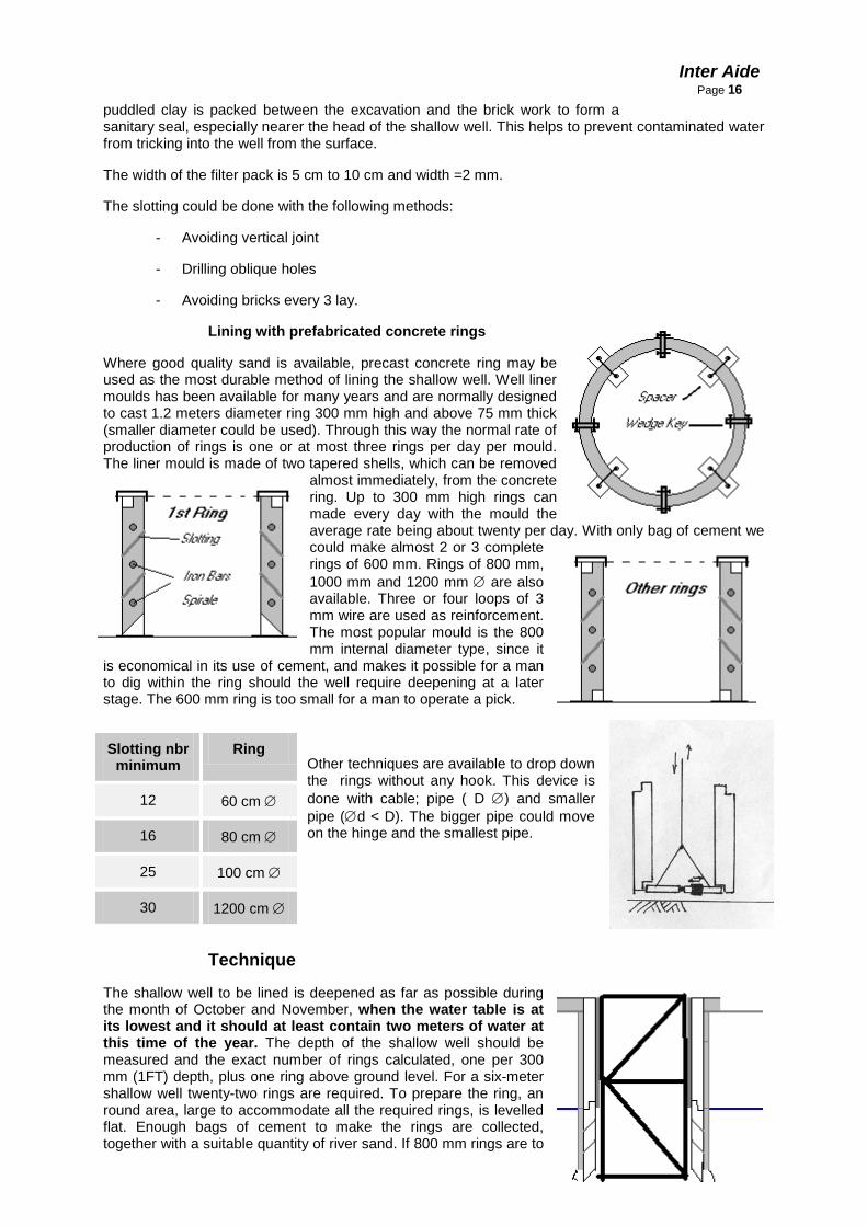
Lining with prefabricated concrete rings
Where good quality sand is available, precast concrete ring may be used as the most durable method of lining the shallow well. Well liner moulds has been available for many years and are normally designed to cast 1.2 meters diameter ring 300 mm high and above 75 mm thick (smaller diameter could be used). Through this way the normal rate of production of rings is one or at most three rings per day per mould. The liner mould is made of two tapered shells, which can be removed
almost immediately, from the concrete ring. Up to 300 mm high rings can made every day with the mould the average rate being about twenty per day. With only bag of cement we could make almost 2 or 3 complete rings of 600 mm. Rings of 800 mm, 1000 mm and 1200 mm ∅ are also available. Three or four loops of 3 mm wire are used as reinforcement. The most popular mould is the 800 mm internal diameter type, since it
is economical in its use of cement, and makes it possible for a man to dig within the ring should the well require deepening at a later stage. The 600 mm ring is too small for a man to operate a pick.
Other techniques are available to drop down the rings without any hook. This device is done with cable; pipe ( D ∅) and smaller pipe (∅d < D). The bigger pipe could move on the hinge and the smallest pipe.
Technique
The shallow well to be lined is deepened as far as possible during the month of October and November, when the water table is at its lowest and it should at least contain two meters of water at this time of the year. The depth of the shallow well should be measured and the exact number of rings calculated, one per 300 mm (1FT) depth, plus one ring above ground level. For a six-meter shallow well twenty-two rings are required. To prepare the ring, an round area, large to accommodate all the required rings, is levelled flat. Enough bags of cement to make the rings are collected, together with a suitable quantity of river sand. If 800 mm rings are to
Slotting nbr minimum
Ring
12 60 cm ∅
16 80 cm ∅
25 100 cm ∅
30 1200 cm ∅

Inter Aide
Page 17 be made, one bag of cement is needed for four rings. Clean the mould and
paint old engine oil on the inner surface of the two shells. Assemble the mould on ground. The concrete is prepared by mixing one bag of cement with five times its volume of river sand (1.5 mixture) and sufficient water to make a dry (stiff) mixture of concrete. The mixture should hold the least possible amount of water to obtain a good concrete and some experimentation should be carried out. If the mixture is too wet, the ring will slump after the mould is removed. Add the mixture between the shells of the mould to a depth of 75 mm and then firmly ram down with rods or wooden sticks. Add a ring of reinforcing wire. Add a further layer of concrete mixture and ram down again. Add another reinforcing wire. Fill the mould completely with the mixture ensuring that it is packed with a solid mixture of concrete. Level off the top of the mixture. The mould can then be removed. Take out the spares and remove the inner shell first, very completely, followed by the outer shell. The shells must remain completely level when being extracted. The concrete ring should stand up by its self without collapsing. The mould can be cleaned and oiled, and the next ring is made in the same way. One mixture of concrete using one bag of cement is processed into rings at one time. The rings are covered to protect them against the sun or rain. They are kept wet for one week in sheltered conditions.
Lining the well
When using this technique, the shallow-well liners are lowered down the well one after the other with the broad base of the liner downwards. During the moulding process three or four holes are left in the wall of the ring, though which wire can be looped and rope attached for lowering. We must make sure that the lowest ring is placed centrally and level on the shallow-well bottom. A further two rings are added on top of the first. A sheet of plastic is then carefully wrapped around the rings to cover the joints. The annular space between the rings and the well is filled either with thoroughly washed river sand or cuttings from the well excavation which must be uncontaminated, and the top half meter of annular space should be filled with concrete. Since the rings do not have a stepped joint, the plastic stops sand from running through the joints between the rings. A further three rings are stacked and the same procedures are followed. Once above the water level, the rings can be cemented together. When shallow well is finished and about to be fitted with a hand pump, usually an Afridev pump, the concrete back fill can be built up to the ground level, and the slab is to be put on top of it.
Lining the well with concrete rings cast " IN SITU "
The technique is fully described in a booklet available from DDF (water Division, Harare ) and the UNICEF Harare. This technique can be used to line wells down to more than 30 meters. After this depth the well is excavated 1.2meters in diameter. Before blasting starts, the upper 1.5 section is lined with concrete which is cast "in situ" using steel shutters.
The shutters, which are 1-meter deep, are first assembled on the shoulder of the lower 1.2 meters section of the well. A concrete mixture made with cement, stone and river sand is mixed and added to the annular space between the well and the shutter. Two bags of cement are normally required for each 1-metre section of lining. The mix is left to set overnight, and in the morning the shuttering is removed, cleaned, oiled and relocated on top of the previous lining and a further one meter of well is lined. Some experimentation is required with locally available materials to obtain a mix that is both economical and strong. The same technique is used up to the surface. An outer shutter is used above the ground level so that a ring approximately 500 mm high is formed at the well. Once the upper lining is set, the well can be blasted through the rock layer and through the water-bearing aquifer to the required depth. In community wells fitted with a hand pump, at least one hundred 50 litres mining buckets of water are required per day, before the well is considered deep enough for community use. The "in situ" method of lining wells is not normally used for upgrading existing well, and may rarely be used as a technique for family wells because it is relatively costly, and heavy specialized equipment is required. However, it is an excellent method of lining wells where funding permits. The final choice of well lining can only be made when local conditions are known.
THE WELL COVER
Once the well is lined, the next stage of protection involves fitting the concrete well cover. Many poorly protected wells built in the rural areas have little more than a few logs placed across the opening of the well as a precautionary measure to protect children. In more advanced traditional technique, logs are placed across the head of the well and these are mortared in position with concrete. Where this technique has been carried out above ground level, the well can be regarded as semi-protected, at least against run-off water.

Inter Aide
Page 18 MAKING THE WELL COVER
All upgraded or protected wells are fitted with a concrete well cover which is cemented to the top well lining. The cover slab is important because it helps to prevent contaminated waste water and other objects from falling into the well. It also makes the well safe for children and provides a clean resting place for the family bucket The diameter of the slab will depend on the well size and should fit neatly over the top well lining. A hole is left on the slab through which a pump can be fitted. The exact size of the hole will vary according to the type of pump to be fitted to the well head. If upgrading a well, the hole is made large enough for a standard an Afridev pump to pass through it. This will normally be about 325 mm in diameter.
Borehole SITING. Where to locate the Borehole? A lot of materials (costing one) could be used but the first requirement is to involve the community in this decision. Drawing a map of the village can also be interesting. When selecting a well location, consideration shall be given to topography, drainage, sources of contaminants and other on-site conditions in order to promote sanitary conditions and prevent contamination of the well and aquifer. When locating wells, all well construction contractors and private drillers shall comply with the regulations of state, county, municipal or local governments, including distances from sources of contaminants, provided those regulations are more stringent than the minimum standards of these Rules and Regulations. (Water Board Malawi and NGO Workshop Minutes where Interaide was one of the members - April 2000)
1. Wells shall not be located closer than one fifty (50) metres horizontally to the nearest existing source of contaminants fifty (50) metres from a septic tank, sewer line or other sources of contamination. Prior to the construction of a well which cannot meet this location condition, a variance request must be approved by the Board. Such variance request, based on hydro-geologic information, shall be prepared by a water well construction contractor, a professional engineer or a professional geologist and shall meet the minimum requirements shown in Figure 1. In no case shall the horizontal distance of the well to the nearest existing source of contaminants be less than 25 feet. Monitoring and observation, dewatering and recovery wells are exempt from this requirement if it conflicts with the intended use of the well.
2. If a well is built to replace another well located less than fifty (50) metres horizontally from a source of contamination, the replacement well shall not be located closer to the source of contaminants and the distance between the perimeter of that source and the base of the grout seal shall not be less than 20 metres as shown in Figure 1 unless a variance request, prepared in accordance with the provisions of rule 1, is granted.

Inter Aide
Page 19 ELECTRICAL RESISTIVITY
Electrical resistivity methods involve the measurement of the apparent resistivity of soils and rock as a function of depth or position. The resistivity of soils is a complicated function of porosity, permeability, ionic content of the pore fluids, and clay mineralization. The most common electrical methods used in hydrogeologic and environmental investigations are vertical electrical soundings (resistivity soundings) and resistivity profiling. During resistivity surveys, current is injected into the earth through a pair of current electrodes, and the potential difference is measured between a pair of potential electrodes. The current and potential electrodes are generally arranged in a linear array. Common arrays include the dipole-dipole array, pole-pole array, Schlumberger array, and the Wenner array. The apparent resistivity is the bulk average resistivity of all soils and rock influencing the flow of current. It is calculated by dividing the measured potential difference by the input current, and multiplying by a geometric factor (specific to the array being used and electrode spacing). In resistivity soundings, the distance between the current electrodes or the distance between the current and potential dipoles is expanded in a regular manner between readings, thus yielding information of the electrical properties of soils from deeper and deeper depths. Models of the variation of resistivity with depth can be obtained using model curves or forward and inverse modeling computer programs. GEOVision geophysicists apply resistivity soundings to:
Characterize subsurface hydrogeology
Determine depth to bedrock/overburden thickness
Determine depth to groundwater
Map stratigraphy
Map clay aquitards
Map salt-water intrusion
Map vertical extent of certain types of soil and groundwater contamination
Estimate landfill thickness In resistivity profiling, the electrode spacing is fixed, and measurements are taken at successive intervals along a profile. Data are generally presented as profiles or contour maps and interpreted qualitatively. Resistivity profiling is used to:
Map faults
Map lateral extent of conductive contaminant plumes
Locate voids
Map heavy metals soil contamination

Inter Aide
Page 20 Delineate disposal areas
Map paleochannels
Explore for sand and gravel
Map archaeological sites Electrical Resistivity
Direct Current Resistivity is useable if those following criteria’s are verified:
• Characterize subsurface hydrogeology
• Determine depth to groundwater
• Map stratigraphy
• Map clay aquitards
• Map salt-water intrusion
• Map vertical extent of certain types of soil and groundwater contamination
• Estimate landfill thicknes
• Determine depth to bedrock/overburden thickness
• Map faults
• Map lateral extent of conductive contaminant plumes
• Delineate disposal areas Electrical or direct current methods measure the bulk resistivity of the subsurface to determine geologic structure and/or physical properties of the geological materials. An electrical current is introduced directly into the ground through current electrodes. The resulting voltage potential difference is measured between a pair of potential electrodes. The current and the potential electrodes are generally arranged in a linear pattern. The apparent resistivity is the bulk average resistivity of all soils and rock influencing the flow of current. Advantages:
Substantial quantitative modeling is possible using either computer modeling or master curves. The resulting models can provide accurate estimates of depths, thickness and electrical resistivities of subsurface layers. Surveys can be completed to depths of several hundred feet.
Limitations:
Resistivity surveys require a fairly large area far removed from power lines and grounded metallic structures. Profiling surveys can be more labor intensive than some other geophysical survey methods.
Surface resistivity measures the electrical resistivity of the subsurface materials, which include soil and groundwater characteristics, from survey stations at the ground surface. Surface resistivity can be used to study lateral changes and vertical cross sections of the natural hydrogeologic setting. Surface resistivity can also be used to study contamination of soil and groundwater and to locate buried objects.

Inter Aide
Page 21
Surface Resistivity Applications: • soil or rock lithology
• soil and groundwater contamination
• saltwater/freshwater interface
• mapping clay layers or sand deposits
• buried object location
• mineral exploration
• water table mapping
• fracture location Surface Resistivity Method Application of the surface resistivity method requires that an electrical current be injected into the ground by surface electrodes. The resulting potential field (voltage) is measured at the surface by a voltmeter between electrodes. The resistivity of the subsurface materials can be calculated by knowing the electrode spacing, geometry of the electrode positions, applied current, and measured voltage. Surface resistivity measurements are reported in the units of ohm-meters or ohm-feet. The depth of the resistivity measurement is related to the spacings of the electrodes and may vary depending on the subsurface conditions. The resistivity unit has a self-contained transmitter, capable of obtaining data to about 50 to 100 meters (160 to 300 feet), using self-contained, rechargeable batteries.
GRAVEL PACK Filter pack is made with coarse or fine gravel (2-3 mm dia) and placed between the borehole wall and screen (see figure 15). Filter packs are used to settle out fine grained particles that may otherwise enter the well and to increase the effective hydraulic diameter of the well. The filter pack can be seen as the "lungs " passing water to the "heart of the well" (the screen). A filter pack should be installed in all wells except those complete in rock, coarse sand or gravel.
Filter material: ideally, the filter media should consist of silica - based material since it will not dissolve over time; this ensures that the integrity of the filter pack is maintained and that harmful or unpleasant substances are not leached into the water
Materials cleanliness: filter materials should be clean because the filter pack should remove dirt from the water rather than add dirt to it. A clean material minimizes filter pack collapse and reduces well development time. Treat all filter materials with 50 mg/L - chlorine solution prior to placement to ensure it doesn't contaminate the well.
Grain size /uniformity: The sand or gravel should be of a uniform size, which is just slightly larger than the size of the slots in the well screen. This is the factor controlling the responsibility of sand pumping. Desert sand; for example, should be avoided because it is too fine and will broke the screen or wash into the well causing turbid water and rapid pump cylinder wear. If there is a wide range of particle sizes, the filter pack can become severely blocked. Alternatively, the course materials may separate as it is poured into the well resulting in possible continued sand pumping
Grain shape: well- rounded and sorted grains from the river or ocean deposits should be used since they will reduce draw down, increase yield and allow for more effective development. Even if rounded

Inter Aide
Page 22 gravel must be transported from far away, local angular rock should not be used
since it will compact when the well is pumped and can severely restrict the flow of water. Finally, flake- like grains are unacceptable because they settle to form a filter media with a low permeability.
Finding materials: the best materials is course silica sand and fine gravel materials which is usually found in river - bed or ocean beaches. Separate the desired size fraction by using two screens, which have slot size of 1/8 and 1/4 inches. Put the screen on top and bottom of a strong wooden flame with the course slot screen on top. After rinsing, suitable materials will be trapped between the two screens.
Filter volume: Calculate the volume of the filter necessary to fill up the well annulus to 2 meters above the top of the well screen (this allows for areas of the Borehole washing out to be filled without exposing the upper screen to formation stabilizer or Borehole fines) Whenever possible, however, do not place gravel within 10-20 feet of ground surface. First determine the desired length of the filter pack, then look -up the required volume.
INSTALLATION: After the casing and screen have been installed, continue to rinse the Borehole by circulating clean ware through the bottom of the casing. Slowly pour the filter media into the annular space and let it settle into the upward flowing water. This process, called "floating in the gravel pack" helps prevent the filter material from bridging and keeps the fines from setting. A feeler line or weighted measuring tape should be used to confirm where the top of the filter pack is.
WELL DEVELOPMENT There are several methods but only one is explained below.
The well screen is the "heart of a well" and the filter pack acts as "lungs" passing water to the screen! However, after drilling a borehole and installing a casing and filter pack, it is necessary to get the "lungs breathing" since the drilling fluid forms a thin layer of mud on the sand grain of the Borehole wall and is force into the pore spaces and cracks in the aquifer. This plugging effect decreases the flow of water into the well.
**The act of cleaning out the clay and silt introduced during the drilling process as well as the finer part of the aquifer directly around the well screen prior to putting the well into service is called "well development " (1) Effective well development:
• Increases the rate of the water movement from the aquifer into the well
• Stabilizes the quifer to prevent sand pumping, thereby producing better quality water and increasing the service life of the pump cylinder and well
• Remove organic and inorganic materials which may inhibit effective well disaffection By ensuring that wells are developed to the best possible technical standards, fewer borehole will be required to meet the total demands; moreover, wells are less likely to fail within a few years. Development should continue until the discharged water is clear. This is difficult because fines from the well and adjacent aquifer have to be removed after the screen and filter pack have been installed. The time required for development depends on the mature of the water bearing layer, the thickness of screen slots relative to aquifer particle size, the amount of materials rinsed from the well prior to placing the filter pack, and the type of equipment and degree of the development desired. Large amounts of developments energy are required to remove drilling fluid containing clay additives. Well development may be completed in 1 hour, but up to 10 hours may be required. (A common development of 6 hours is still used). * Well development methods are based on establishing velocities of flow greater than those produced by the expected rate of the pumping from the completed well. Ideally, this is combined with vigorous reversal of flow (surging) to prevent sand grains from bridging against each other. Movements in only one direction, as when pumping from the well, does not produce the proper development effect - sand grains can "bridge" voids around the screen. Agitation from pumping during normal pump use may cause these bridges to break down over and sand to be pumped. This sand will act like sandpaper in the pump cylinder and will cause the cup leather to wear -out and the pump to fail within a few days or weeks!

Inter Aide
Page 23 As discussed below, there are a number of techniques that can be used to
develop newly built wells. Although hydraulic jetting and hydraulic fracturing are efficient well development techniques, they are not covered in this manual since they require sophisticated commercial equipment and specialized training and are usually used in developing large capacity wells. OVER PUMPING This is the simplest but least effective development methods: it consists in pumping a well at 2-3 times the designed discharge rate for a prolonged period. This does not really agitate the soil enough to create a real filter around the screen and it tends to develop only a short section of the length of the screen. However, it is useful because if the well can be pumped sand free at a high rate, it can be pumped sand free at a lower rate. If the water level is within 10 to 15 feet of the ground surface, it is sometimes possible to use the mud pump as a suction pump to pump water from the well for 2 to 3hour. If this can be done, do not pump continuously: start - stop cycle pumping is best for developing a well. If this is not possible, install the bush pump and use a separate cylinder for the development process since particules removed during development can cause an abnormally high rate of wear on the pump resulting in early pump failure. Using a larger cylinder than planned for the final installation will enhance the effectiveness of the well development. The effectiveness of over pumping can also be enhanced by attaching the rubber gasket around the top of the cylinder and lowering it into the well until it is adjacent to the top of the well screen. Start developing the well at the top of the screen so that fine materials around the screen can gradually loosen and be pumped out of the well without jamming the pump! When pumping no longer produces sediments, the pump can be lowered several feet using especially made half length connecting rods and quarter length drop pipe (also known as draw pipe or pump column). The cycle of the pumping until the water clears and lowering the pump further into the screened interval should continue until the entire screen has been developed. Attaching a second gasket 0.5 -1 meter below the bottom of the pump cylinder would greatly increase the suction effect of the isolated section of the screen. BACK WASHING also is a relatively simple method of developments; it requires a water lifting device and container in which water can be stored and then from which it will be allowed to flow easily back into the well. Water is pumped to the surface until the container is full; it is then rapidly dumped back into the well. Repeating this motion many times can provide some development of the surrounding water bearing formation. It is crucial that water, which is pumped to the surface, be allowed to sit until the suspended material has settled. The clear water should then be decanted into a second container and from there dumped back into the well. This will ensure that fine particules are not inadvertently re-introduced into the well. If the gasket has not been attached to the top of the pump cylinder, it may be possible to contribute over pumping with hand washing by collecting water from the over-pumping process, allowing it to settle and then rapidly pouring the decanted water back into the well. SURGING: Surging is the most common method of well development. It consists in forcefully moving water into and out of the well screen using one of the following techniques: COMPRESSED AIR: compressed air can be injected into the well to lift the water; as it reaches the top of the casing, the air supply is shut off, allowing the aerated water column to fall (process called "rawhiding" ) The air supply should be periodically run without stopping to pump sedimates from the well (3) The equipment is usually not available in remote areas and often only open a small portion of the screen. BAILER: Bailer is like a length of the pipe with a one way valve in the bottom. The bailer is lowered into the well until it fills with water and sediments; it is then pulled to the surface and emptied. Bailers up- and - down motions causes a surging action which will develop the area around the screen. The heavier and wider the bailer is, the better it will function because it will have more force to push water through the screen. Be prepared to bail and bail and bail…. It is hard work and can take all day! SURGE BLOCKS: A Surge block is a flat seal that closely fits the interior casing and is operated like a plunger beneath the water level. Because it is closely sealed to the casing, it has a very direct positive action on the movement in the well. Placing a surge block on the end of the water tubing equipped with a one-way valve has the advantage of the down stroke being milder than the upstroke because some water passes up the tubing. This is advantageous because it ensures that fines are not in formation and it helps to remove
Inter Aide
Page 24 sediments, which is loosened by the surging action. This prevents the screen
from becoming totally blocked with accumulated fines. To surge a well effectively, apply an up and down motion, repeatedly raising and dropping plunger 2 to 3 feet. The plunger should drop rapidly on the down stroke so that turbid water can be lifted out above the surge block will make it easier to work for a longer period of time. Surging should start above the screen to reduce the possibility of "sand- locking" the surge block. Initial surging should be with a long stroke and at a slow rate (20 to 25 strokes per minutes); after surging above the screen, the hole should started at the lower end of the screen - gradually working upwards until the entire screen has been developed. When the amounts of fine material draw into the well begins to decrease, the process should be repeated, beginning at the bottom of the screen, but with a faster stroke (30 to 35 strokes per minute). The final surging should be as rapid as possible for as long as possible. TESTING WELL YIELD Well yield is the volume of the water that can be pumped during a specific period of time (it is expressed as litres of gallons per minute). Some times the yield of existing well can be tested to determine if it is worth while drilling in the same area. If a submersible pump is installed, a full pump test can be done (4) If hand pump is installed, try to measure level before and after pumping. Pump at a steady rate for as long as possible (1-4 hours if new wells will be heavily used). This pumping rate is sustainable if the water level returns to the pre-pumping level within 6-12 hours. The shorter the time, the better the aquifer If the yield of a newly drilled well is questionable, it is often a good idea to test it to determine whether or not it is worth while to pour concrete pad and install a bush pump. In general, a well which is capable of supporting a heavily used bush pump should be able to yield at least 0.21/s (3 gal /min) and have a specific of at least 0.011/s for every meter of drawdown (5) Rough estimates of the yield of new water wells can be obtained by using an air compressor, water tubing equipped with a foot valve or a bailer If available, use an air compressor to inject large volume of air into the well. This will cause the water to spoil over the top of the well casing. A trench should be prepared ahead of time to carry this water away so that it does not form a pond around the well. After 30minutes, the amount of water still flowing over the top of the well casing will provide a rough estimate of how much water the well can produce. This should be confirmed by turning off the pump and measuring how long it takes for the water in the well to return to the pre-pumping level. Measure the water level every minute for 10 minutes, then every 5 minutes for half an hour, then every 15 minutes for half an hour until recovery is complete. The reading can be used by hydro-geologists to analyse the aquifer. Finally, an inertia- lift system (water) or a bailer can be used to test the yield of a newly constructed well. If the well can be pumped dry using these devices and the yield does not improve with development, the well will not have sufficient yield to support a hand pump. If the yield of a well is inadequate to support a hand pump, the well should be abandoned by removing as much casing as possible and filling the well with clay or silk sand and filling the top 2 meters with concrete. If this is not done, future well supplies may be jeopardized since the well may allow contamination to pass into the ground water FOOTNOTES AND REFERENCES
1. In sand and gravel, filter packs are often created by developing the well so that 30 to 60 percent of the quifer material adjacent to the screen passes into the well leaving a hydraulically graded filter of coarse sand and gravel around the screen
2. For a given pumping rate, the less development will take place in the lower part of the screen. After fine material has been removed from the permeable zone near the top of the screen, water entering the screen moves preferentially through these developed zones, leaving the rest of the well poorly developed and contributing little to well yield.
3. If limited volumes of air are available, put a small diameter air hose down a larger pipe (such as the drop pipe, Water tubing or drill pipe); blowing air through the small air hose will cause to lift out through the larger pipe. A useful rule of thumb for determing the proper compressor capacity for air -lift pumping to provide about 3/4 cfm of air for each 1 gpm of water at the anticipated pumping rate. In general, a compressor producing 125 psi and 200 cfm is required. Submerse the air line about 60 percent of its length during pumping.
4. Using a submersible pump, a pump test can be done as follows:

Inter Aide
Page 25 • Measure the distance to the water level in the well
• Then turn on and operate the pump at about one- third its capacity for 1 to 4 hours
• During the pumping, measure the yield of the pump by filling a container of known volume and recording the length of times it takes to fill it. For small container, the flow rate (GPM) =(volume in gallons x 60)/ time (seconds) to fill. For the typical 55-Gallon oil drum, the pumping rate in 1/s is 209/Time (seconds)
• At the end of the pumping period, measure the level as soon as the pump is turned off.
• Calculate the draw down by subtraction the original depth of the static from the new depth
• Calculate the" specific capacity" of this one third draw down point by dividing the yield ( how many litres collected in the barrel in one minute) by the drawdown
• Repeat this process pumping at two-thirds of the pumps capacity and then again at a full capacity
• If water level measurements are frequently taken during drawdown and recovery, hydrogeologists can use the information to calculate the aquifer characteristics (transmissivity and storativity) which can be to help develop local ground water development plans. 5 Note that if test are conducted immediately after a well is constructed and before it is put into full use, incomplete development will often cause the calculated yield to be 10-30 percent less than the yield after 2-4 weeks of continuous use.
ACCEPTANCE OF A BOREHOLE THROUGH THE PUMPING TEST METHOD. Introduction
The underground work is described by different characteristics like heterogeneity, unseen construction, idealisation and models of use.
The seasonable characteristics are giving incertitude on the availability. But it’s necessary to ensure the expected work and avoid losing investment.
The sustainability of Community participation will also depends from the work strength. That means it is a very important criterion for that issue.
After so many wrong ways used by driller and supervisors we decided it was necessary to implement our own pumping test.
In the past only one criterion was used to certify a borehole before to begin the construction or rehabilitation. But so many other factors are coming into the well-managed Borehole.
Earth Sciences for Borehole
We can analyse the ground environment and put some hypothesis on the earth
o Heterogeneity
o Darcy’s Law materials
o Unlimited environment

Inter Aide
Page 26 So as we can see on figure n°1, without having perturbation the ground
water (first level) is maintaining its level at static level. When we are pumping we can observe any moving level ( called dynamic level). Around the borehole, we can see some slope in the ground water level. It shows us an horizontal yield.
Characterisation of the Borehole The following characteristics have to be considered when we describe a borehole:
o 1. Max Pumping yield.
o 2. Static water Level.
o 3. Qualitative criteria for the development in the Borehole.
o 4. Stability of the pumping test.
o 5. Dynamic Water Level for the finally yield.
o 6. Graphics to characterise the pumping and recovery.
o 7. Date and time of pumping
o 8. Water Quality and water colour. To regroup those quantitative and qualitative characteristics will be difficult. Nevertheless it will be possible to summarise the seven first characteristics in one procedure criterion. The other characteristic should be analysed separately. Theoretical analyse Short term analyse. Without any perturbation the ground water should stay at the same level called the static water level. In the first step when the Borehole is drilled we consider that this work doesn’t modify the ground water level and volume. This work insert only a singular perturbation without any consequence on the ground. The second consideration is that the pumping shouldn’t modify the ground water volume. This simplification is still good for a short time analyse (less than 20 days analyse) According to those two considerations, the water level should stay at the same level. But unfortunately it isn’t happening. All the reasons are coming from the water breakage due to the partial permeability and non-permeability. The interpretation of the breakage will be done by Bernouilli and Piesometric analysis. The objective way is to explain the pressure in term of depth. With the static analyse we have an equality for potential energy . But for dynamic analyse one part of the loss of the depth is due to the existing flow and so the waste of the fluid movement.
Two terms are coming from the breakage. Considering the s1: the static water level and s2 the dynamic one for the considered yield Q. The appearing constant alpha and Beta are fixed for the borehole. α Q is showing the linear and laminar breakage.

Inter Aide
Page 27 β Q² is showing the quadratic and turbulent breakage.
Note: Explanation for turbulent and laminar: For most people those terms do not mean anything. But as an example we can try to understand the meaning. If you have ever observed a river with a strong and regular flow. If a turbulent flow arises, it will cause a loss of energy. We can thus observe two different behaviour that it will be important to consider. The term of turbulent breakage determines the quality and acceptability of the borehole.
The first static level called s1 (Static level means that the flow Q1 = 0): If we are taking two different Yield and therefore two different dynamic levels s2 and s3. We know s1, s2, s3, Q2 and Q3 and there remain two equations with two unknown value alpha and Beta.
Transforming the previous equations according to (1’)=(1)/Q2-(2)/Q3
We can also consider that the static water level is never accessible. It is quite true when the pumping test is done only some hours after the development. And this happens so many times. So we have to wait for the stability of another yield In this way we still have got 2 unknown values and six measured values (s2, s3, s4, Q2, Q3 and Q4) We cannot fix the needed time for the pumping test: it depends on the view and acceptable stability of the different yields. This also constitutes a criteria. It’s still important to define these criteria: the stability is the following one. For a constant yield the level has to remain unmodified for more than 5 cm during 10 minutes. A higher modification means an instability. In this way the graphic should be a good way. The data have to be taken almost every 5
minutes. It will show us a graphic like the following one. Recovery during 45 to 60 minutes to crosscheck the information data’s
This graphic is showing the dynamic level during pumping and recovery. But it doesn't characterise the Borehole. To do it, we

Inter Aide
Page 28 need to take the first equation
And s1 = 0 and α = -B and β = -C So the equation is moving into s2 = B Q2 + C Q²2 The Quadratic term is the most efficient to characterise the State of Borehole and plugging up
C< 675 m/(m3/s)² Good borehole Correct development
675<C<1350 m/(m3/s)²
Poor borehole Useable but cleaning needed
C > 1350 m/(m3/s)² Plugged up borehole Need to be developed completely
C>5400 m/(m3/s)² Totally broken borehole Unusable
Recovery time will give us also a very good idiea on the filling process. Then it will be important to consider casing capacity and the reduction of effective section with the installed materials Long term analyse. The long term Analysis will be based on the extrapolation factors. We can sometime estimate that evolution
Model 1: So some terms has to be described. Time (t) = T-T0 within T =0 on 1st January and T is counted day (for example: if we are on 5th July so T = 186) T0 is the end of rainy season day. In 2000 ( on 12 May) it means T0 = 132. We then insert two other constants who are dependant from topology and type of soil. A: Coefficient dependant from the type of soil (small value for permeable soil and high one for non permeable) B: Coefficient dependant from the topology ( 1 for a flat land >1 for a concave land and <1 for a convex one or slope)
But a lot of other factors are included in the natural behaviour. So it is not easy to find a complete and perfect model.

Inter Aide
Page 29
Practical Measure of s(Q) The way to use the pumping test on the field will be defined for the adaptable and disposable materials.
Materials 1. Pump:
Jaccuzi Model Zx10 serial 065020
Best eff 45m Max depth: 70m
Max flow 183l/min
KW 1.5 kW
120l/min @21m
cos phi: 0.88
2. Control Box:
Franklin Electric
Europa GmbH-D- 54516 Wittlich
1.5 kW 230V 11.1 A
Input 1 phase from Generator
Output 3 phases
3. Cable:
Tri phases. Coaxial length 60m
4. Generator:
220v 3kVA Yamaha
5. Pipe (flow):
1" diameter Polyethylene
6. Pipe (depth control):
1/2" diameter Polyethylene
7. Rope: 8. Electric wire 9. Soft wire 10. Battery 11. Indicator 12. Flow meter 13. Tap-valves Process Method 1° Install the material correctly with enough place and protection for electrical materials ( direct the flow far from ( be careful about the high volume of water) 2° Insert electrical and soft wire into depth control pipe. And measure the s0 depth with the insert level. Measure also the depth of the pump. 3° Open a little the valves and switch on all the system

Inter Aide
Page 30 4° Fill the next grid every 5 minutes with
5° The flow should have to be maintained like following Minutes 0 to 60 Yield Q1
Minutes 60 to 120 Yield 0 Minutes 120 to 180 Yield Q2 Minutes 180 to 240 Yield 0 Minutes 240 to 300 Yield Q3 Minutes 300 to 360 Yield 0

Inter Aide
Page 31
Civil Work Some notes on civil work are written here under:
1° Digging of the foundation.
A. For all the work, almost the first 25 cm of soil (organic, contaminated soil or growing clay) has to be removed. When soil is moved it cannot be placed back. B. The foundation supports tthe whole weight of the building. The foundation will support wall, pump structure and also washing slabs.
C. The foot of the pump has to be solidly fixed into the foundation. This pump will receive more than 6000 waves a day. For the borehole, a concrete cylinder is keeping 50 to 60 cm of the casing.
D. For a standard building the foundation goes 60 to 70 cm into a compacted soil.
E. Some drainage going trough the building can be done to avoid water under the construction.
2° Foundations. A. In the Bottom of all foundations (except other used techniques) a first layer of rock of 15 to 20 cm has to be built. B. A first concrete layer of 5 cm (1/3/2) is done. The water part has to be reduced (dry concrete) E/C = 0.45 ( See concrete part).
C. The foundation width has to be increased by 5 to 10 cm comparing to the wall. The remaining of the foundation is bricks.
3° Walls. A. The wall height is fixed at 1 m and bricks are aligned on both sides. B. The bricks joints should be less than 1 cm. An strong supervision has to be done.
C. Angles are 90° and building chair could be required.
D. For the walls over 8 meters in length a dilatation joint is required but not for those ones under 8 meters. l
4° Washing slabs. A. They are linked to the construction and the height is a little lower than the walls. B. The water evacuation has to be done. Slopes of 1 to 2% are efficient in term of direction. The sink pipe is 1 ‘’∅.
C. Inside the washing slab the filling is done with rocks and bricks but no soil. A plastering is required around the washing slab ( max 1m from the slab) to avoid erosion during washing clothes.
5° The cattle grid. A. A cattle grid is fixed to prevent small animals from entering. B. The level is almost 25 cm.
6° Pointing. A. Before pointing the mortar is more than 1 day old.

Inter Aide
Page 32
B. To avoid cracks the plastering, pointing and copping are done under protection from the sun. It could be done according to the time of the day time or by covering during the drying.
C. If the surfaces are too dry there have to be wet before pointing, plastering, copping.
7° Plastering. A. It should not dry too quickly: the solution is to cover the place. B. The corners are rounded to avoid weak angles. The width is between 1 to 2 cm.
8° Copping A. A precast copping element can be done. It’s also possible to proceed on the field but the following design must be respected.
9° Floor. A. Special care is required for the under floor, the foundation of the floor. A rock layer of almost 15 cm is put before concrete to drain and strengthen the ground. B. The minimum for the slope is 1.5 to 2%to bring the water to the water way.
10° Water Way. A. A first format is done with bricks. B. The slopes are min 2% The water way is 8 to 14 m long to bring the waste water to natural drain or artificial one.
C. The end of the water way should evacuate the waste water without erosion. A drain network can be made.