Trailer Brake Valves · Hydraulic remotely powered brake system for trailers in agricultural...
16
Trailer Brake Valves Shut-down brake valve, BV1 Nominal pressure: p nom = 250 bar Flow: Q max = 100 l/min RE 66 137/05.11 Replaces: RE 66 137/11.08 Table of contents Content Page General 2 Determining the control piston Ø 3 Characteristic pressure build-up 4 Shut-down brake valve: pipe construction 6 Flange construction 10 Spare parts 15 Assembly notes 16 Features Hydraulic remotely powered brake system for trailers in agricultural vehicles – priority function for hydraulic trailer brake – for use in OC or LS systems – proportional deceleration between tractor and trailer – simple matching of the trailer brake to the tractor brake – limitation of the max. trailer brake pressure – simple integration in the hydraulic system – pressure safeguarding for trailer brake pressure max. 150 bar
Transcript of Trailer Brake Valves · Hydraulic remotely powered brake system for trailers in agricultural...
Trailer Brake Valves
Shut-down brake valve, BV1
Nominal pressure: pnom
= 250 bar
Flow: Qmax
= 100 l/min
RE 66 137/05.11
Replaces:
RE 66 137/11.08
Table of contents
Content Page
General 2
Determining the control piston Ø 3
Characteristic pressure build-up 4
Shut-down brake valve:
pipe construction 6
Flange construction 10
Spare parts 15
Assembly notes 16
Features
Hydraulic remotely powered brake system for trailers
in agricultural vehicles
– priority function for hydraulic trailer brake
– for use in OC or LS systems
– proportional deceleration between tractor and trailer
– simple matching of the trailer brake to the tractor brake
– limitation of the max. trailer brake pressure
– simple integration in the hydraulic system
– pressure safeguarding for trailer brake pressure max. 150 bar
P
SI
XLS
T
Fahrzeugbremse Hauptbremszylinder Anhängerbremse
Fahrzeug
B
AnhängerLogisches „und“-Ventil
BremsventilBremspedale
X1 X2
2/16 Bosch Rexroth AG Hydraulics BV1 RE 66 137/05.11
General
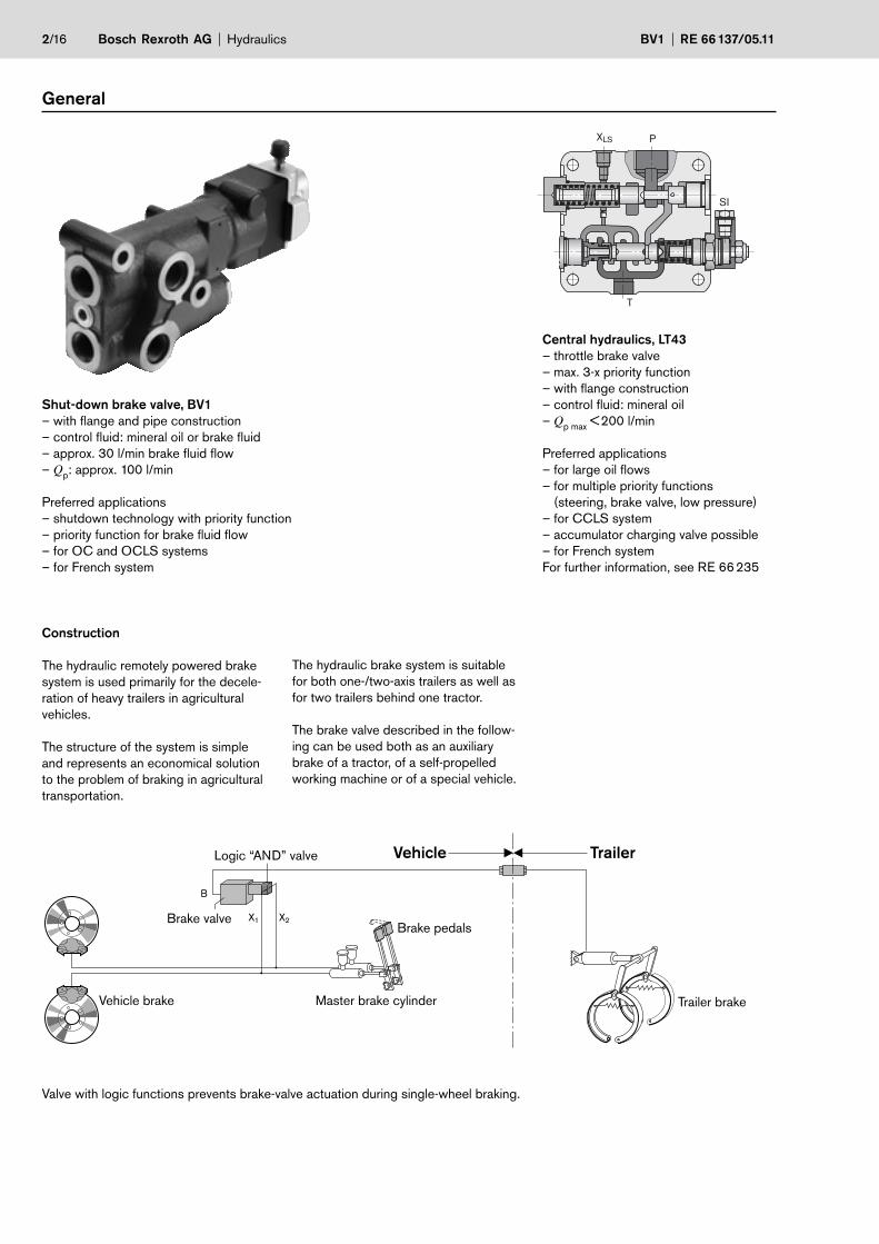
Shut-down brake valve, BV1
– with flange and pipe construction
– control fluid: mineral oil or brake fluid
– approx. 30 l/min brake fluid flow
– Qp: approx. 100 l/min
Preferred applications
– shutdown technology with priority function
– priority function for brake fluid flow
– for OC and OCLS systems
– for French system
Central hydraulics, LT43
– throttle brake valve
– max. 3-x priority function
– with flange construction
– control fluid: mineral oil
– Qp max
< 200 l/min
Preferred applications
– for large oil flows
– for multiple priority functions
(steering, brake valve, low pressure)
– for CCLS system
– accumulator charging valve possible
– for French system
For further information, see RE 66 235
Construction
The hydraulic remotely powered brake
system is used primarily for the decele-
ration of heavy trailers in agricultural
vehicles.
The structure of the system is simple
and represents an economical solution
to the problem of braking in agricultural
transportation.
The hydraulic brake system is suitable
for both one-/two-axis trailers as well as
for two trailers behind one tractor.
The brake valve described in the follow-
ing can be used both as an auxiliary
brake of a tractor, of a self-propelled
working machine or of a special vehicle.
Valve with logic functions prevents brake-valve actuation during single-wheel braking.
Logic “AND” valve
Brake valveBrake pedals
Trailer brakeMaster brake cylinderVehicle brake
Vehicle Trailer

20 40 15014012010060 80
20
40
60
80
100
120
140150
ddd XXX
= 1
4mm
= 2
0mm
d X=
22m
m
d X d Xd X=
12m
m
Xd=
16m
m
= 1
0mm
= 6
mm
= 8
mm
bA
nhän
gerb
rem
sdru
ck p
[bar]
[bar]Schlepperbremsdruck pX
Hydraulics Bosch Rexroth AGRE 66 137/05.11 BV1 3/16
– Hydraulic trailer brake system with
pressure build-up principle.
– Simple integration of the trailer brake
valve in the existing tractor hydraulics.
– System with high power density and
small device size.
– Simple operation of the trailer brake
from the tractor.
– Possible control both with hydraulic or
mechanical tractor operating brake as
well as with single-wheel brake.
– Easy to match the trailer brake to the
tractor brake.
– System with simultaneous and propor-
tional deceleration of the tractor and of
the trailer.
– Hydraulic energy requirement only
upon initiation of the braking operation
and for correcting the brake pressure.
– Simple, low-loss limitation of the max.
deceleration of the trailer.
– Braking force and braking time for the
trailer independent of the operational
state of the tractor hydraulics.
– Relatively short response time (approx.
50 ms) of the trailer brake system.
– Parallel operation of the brake system
with the tractor hydraulics is possible.
– No additional costs for the energy
supply of the remotely powered brake
system of the trailer.
Determining the control piston Ø
Control piston Ø Pressure ratio Control volume,
shut-down brake valve
dx [mm] i
dV
x [cm3]*)
6 1: 1 0.18
8 1:1.78 0.32
10 1: 2.78 0.50
12 1: 4 0.72
14 1: 5.44 1.0
16 1: 7 1.3
20 1:11.11 2.0
22 1:13.44 2.41
*) Vx = control volume of piston 6
The hydraulic trailer brake valve enables
a proportional deceleration between trac-
tor and trailer. To adjust the two brake
systems, the brake pressures pb and p
x
are matched to one another.
The following relationship exists for these
two brake pressures:
px =
db2
= id (pressure ratio)p
b d
x2
Where:
px – tractor brake pressure in bar
pb – trailer brake pressure in bar
db – diameter of control piston 2
on surface 13
db = 6 mm
dx – diameter of control piston 6 in mm
For the piston diameter dx of control
piston 6 in the trailer brake valve, this
yields:
p
bdx = 6 · ��
p
x
The piston diameter dx is adjusted to
match the two brake pressures.
Design example
Maximum trailer brake pressure
pb = 150 bar.
Maximum tractor brake pressure
px = 33 bar.
Calculated piston diameter
150dx = 6 · �� mm = 12.8 mm
33
Selected piston diameter
dx = 12 mm.
Piston diameter dx of control piston 6
in the trailer brake valve.
(Theoretical relationship between
pb and p
x)
Remarks
In draft standard ISO 5697, the following
values are defined for the hydraulic trailer
brake system:
1. The system must be operationally safe
for max. 150 bar.
2. The necessary maximum deceleration
of the trailer should occur at a trailer
brake pressure pb from 120 to 150 bar.
The matching of the two pressures pb
and px (selection of control piston 6) is
performed by the tractor manufacturer.
Matching is selected so that no unstable
driving conditions arise in the tractor.
Tractor brake pressure px
Traile
r b
rake p
ressure
pb

0 2 4 6 8 10
pP pB pY
12
[sec]
14 16 18 20 22 24
150
125
100
0
25
50
75
[bar
]
4/16 Bosch Rexroth AG Hydraulics BV1 RE 66 137/05.11
Shut-down brake valve
Fixed pump and variable pump: Advantage
– energetically favorable behavior
– pump (pP) switches off after neces-
sary brake pressure is reached and
switches back on if the brake pressure
drops below the permissible value.
Disadvantage
– when the pump switches on, small im-
pacts may be audible or small impacts
may be perceptible in the brake pedal.
– max. pressure build-up in approx. 7
switching stages.
pP = pump pressure pB = brake pressure pY = control pressure
Pressure build-up (slow) with read-
justment frequency

Q2Q0 Qmax
PV
PN
PV
NutzleistungVerlustleistung
PN
0
P2
Pmax
pQ0
0Q2
P2
Pmax
p
tPVPN
P
0
QmaxPVPN
Q00
Q2
P2
Pmax
p
tPVPN
P
0
QmaxPVPN
Q2Q0 Qmax
PV
PN
PV
NutzleistungVerlustleistung
PN
0
P2
Pmax
p
Hydraulics Bosch Rexroth AGRE 66 137/05.11 BV1 5/16
Constant flow system, characteristics
Load not actuated Shut-down brake valve is actuated
Closed center load sensing system, characteristics
Load not actuated Shut-down brake valve is actuated
PN Effective power
PV Dissipation power
PN Effective power
PV Dissipation power
X
R
B
N
P
pN – pR > 3.5 barQ [l/min]
pN – pR < 3.5 barRange
36±0.5
56–0.556+0.2
25–0.825+0.6
100 –
310
0+2
88±0
.2
41–0.841+0.6
46±0.57
B
48,5+248.5–1
P23±0.4
= 14+5 Nm
= 2.5+1 Nm
Bleed valve
RE
35±0.4
67
8.6 (2x)
= 10+3 Nm
25.5
±0.420
±0.4
64±0
.4 46
20.5±0.4
X
= 20.5+5 Nm
R
N
N
E
Y
= 56+19 Nm
11–0.611+0.4
36+2
186
163,5–0.9163.5+0.4
107,5–1.5107.5+0.8
128–0.7128+0.2
B
P
pN = pR
p [b
ar]
0012
543
10 20 30 40 50 60
Rex
roth
6/16 Bosch Rexroth AG Hydraulics BV1 RE 66 137/05.11
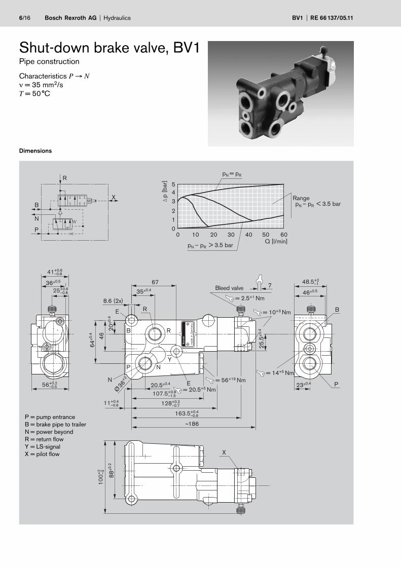
Shut-down brake valve, BV1Pipe construction
Characteristics P → N
ν = 35 mm2/s
T = 50 °C
Dimensions
P = pump entrance
B = brake pipe to trailer
N = power beyond
R = return flow
Y = LS-signal
X = pilot flow

Rex
roth
46–0.3
186 56
110
163.5
YY
RB
PN
P
B
1
Hydraulics Bosch Rexroth AGRE 66 137/05.11 BV1 7/16
Characteristics
Design Proportional control valve with priority function
Line ports Screw-in thread, see order details on page 9
Installation position Bleed valve at top, vertical
Ambient temperature –25...+60 °C
Hydraulic fluid to trailer brake Mineral-based hydraulic oils acc. to DIN/ISO,
other fluids, e.g. environmentally acceptable fluids, on request
Hydraulic fluid in control head Mineral-based hydraulic oils acc. to DIN/ISO,
other fluids, e.g. environmentally acceptable fluids, on request.
ATE brake fluid
Viscosity 10...400 mm2/s
Temperature of hydraulic fluid –25...+80 °C
Filtration Oil contamination class 10 acc. to NAS 1638 obtained with filter �25
= 75
Permissible peak pressure P: 250 bar; N: 250 bar; B: 150 bar, R: see assembly notes on page 16
Nominal flow 80 l/min; > 80 l/min on request
Installation position BV1, pipe construction
B PN
YR
Rexroth
322
5555 6 7
8 9 10
X
52
X
23
36
35,5
51
0,5
5
X
X
X
4
36
23
52
425
5
X
X2X1X2X1
X2X1
8/16 Bosch Rexroth AG Hydraulics BV1 RE 66 137/05.11
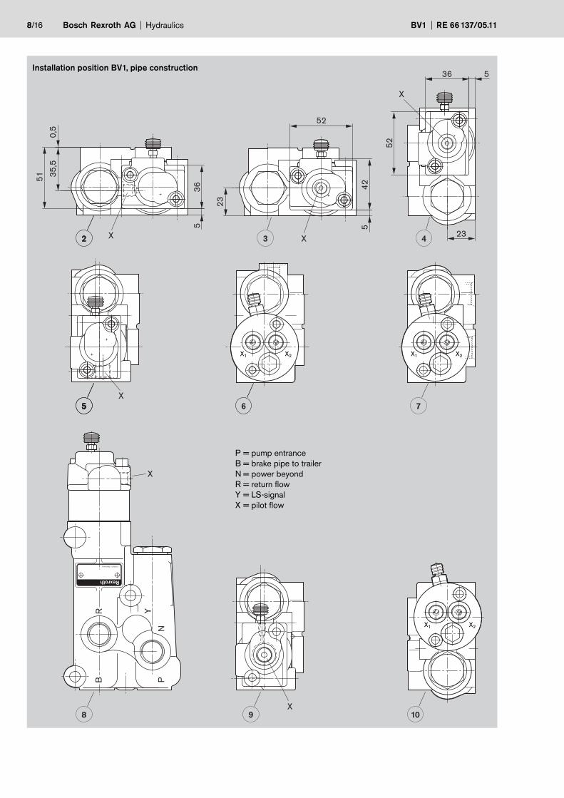
Installation position BV1, pipe construction
P = pump entrance
B = brake pipe to trailer
N = power beyond
R = return flow
Y = LS-signal
X = pilot flow
Hydraulics Bosch Rexroth AGRE 66 137/05.11 BV1 9/16
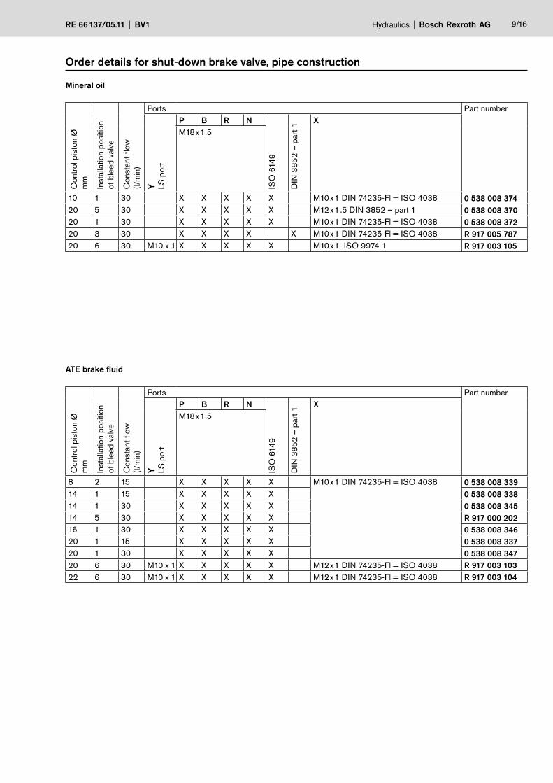
Order details for shut-down brake valve, pipe construction
Mineral oil
Contr
ol p
isto
n Ø
mm
Insta
llation p
ositio
n
of
ble
ed
valv
e
Consta
nt
flow
(l/m
in)
Ports Part number
Y LS
port
P B R N
ISO
614
9
DIN
38
52
– p
art
1
X
M18 x 1.5
10 1 30 X X X X X M10 x 1 DIN 74235-Fl = ISO 4038 0 538 008 374
20 5 30 X X X X X M12 x 1.5 DIN 3852 – part 1 0 538 008 370
20 1 30 X X X X X M10 x 1 DIN 74235-Fl = ISO 4038 0 538 008 372
20 3 30 X X X X X M10 x 1 DIN 74235-Fl = ISO 4038 R 917 005 787
20 6 30 M10 x 1 X X X X X M10 x 1 ISO 9974-1 R 917 003 105
ATE brake fluid
Contr
ol p
isto
n Ø
mm
Insta
llation p
ositio
n
of b
leed
valv
e
Consta
nt
flow
(l/m
in)
Ports Part number
Y LS
port
P B R N
ISO
614
9
DIN
38
52
– p
art
1
X
M18 x 1.5
8 2 15 X X X X X M10 x 1 DIN 74235-Fl = ISO 4038 0 538 008 339
14 1 15 X X X X X 0 538 008 338
14 1 30 X X X X X 0 538 008 345
14 5 30 X X X X X R 917 000 202
16 1 30 X X X X X 0 538 008 346
20 1 15 X X X X X 0 538 008 337
20 1 30 X X X X X 0 538 008 347
20 6 30 M10 x 1 X X X X X M12 x 1 DIN 74235-Fl = ISO 4038 R 917 003 103
22 6 30 M10 x 1 X X X X X M12 x 1 DIN 74235-Fl = ISO 4038 R 917 003 104

Y
Rex
roth
64.5±1
26±0
.4
60
19
36
pN = pR
p [b
ar]
0 10 20 30 40 50 60
33–0.433+0.4
42–0.442+0.4
81
100
62
9690
62
33.5max. 3 40.5
45.9
30
8.6
(3x)
23m
ax.
14.2
540.5
61
= 14+5 Nm
= 2.5+1 Nm
= 10+3 Nm
B
E16
35
25Ø
= 20.5+5 Nm
= 14+5 Nm
234
9±0
.510
9
X
59.5
31.7
5
25.2
59.75
218
79
X
R
B
N
P 012
543
pN – pR > 3.5 barQ [l/min]
pN – pR < 3.5 barRange
= 56+19 Nm19
57
7
Bleed valve
R
N
P
B45°
10/16 Bosch Rexroth AG Hydraulics BV1 RE 66 137/05.11
Shut-down brake valve, BV1Flange construction
Characteristics P → N
ν = 35 mm2/s
T = 50 °C
Dimensions
P = pump entrance
B = brake pipe to trailer
N = power beyond
R = return flow
Y = LS-signal
X = pilot flow
1
B
2
4
3
X2X1
X2X1
Flange surface
Flange surface Flange surface
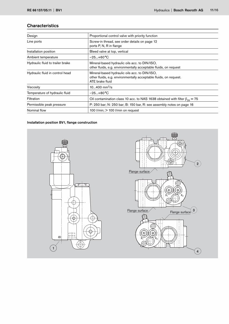
Hydraulics Bosch Rexroth AGRE 66 137/05.11 BV1 11/16
Characteristics
Design Proportional control valve with priority function
Line ports Screw-in thread, see order details on page 12
ports P, N, R in flange
Installation position Bleed valve at top, vertical
Ambient temperature –25...+60 °C
Hydraulic fluid to trailer brake Mineral-based hydraulic oils acc. to DIN/ISO,
other fluids, e.g. environmentally acceptable fluids, on request
Hydraulic fluid in control head Mineral-based hydraulic oils acc. to DIN/ISO,
other fluids, e.g. environmentally acceptable fluids, on request.
ATE brake fluid
Viscosity 10...400 mm2/s
Temperature of hydraulic fluid –25...+80 °C
Filtration Oil contamination class 10 acc. to NAS 1638 obtained with filter �25
= 75
Permissible peak pressure P: 250 bar; N: 250 bar; B: 150 bar, R: see assembly notes on page 16
Nominal flow 100 l/min; > 100 l/min on request
Installation position BV1, flange construction

12/16 Bosch Rexroth AG Hydraulics BV1 RE 66 137/05.11
Order details for shut-down brake valve, flange construction
Mineral oil
Contr
ol p
isto
n Ø
mm
Insta
llation p
ositio
n
of
ble
ed
valv
e
Consta
nt
flow
(l/m
in)
Ports Part number
Y LS
port
B
ISO
614
9
X
14 2 30 M10 x 1 M18 x 1.5 X M12 x 1 DIN 74235-Fl = ISO 4038 0 538 008 413
20 1 30 M18 x 1.5 X M10 x 1 DIN 3852 – part 3 = ISO 6148 0 538 008 410
20 2 30 M18 x 1.5 X M10 x 1 DIN 3852 – part 1 0 538 008 414
20 1 30 M18 x 1.5 X M10 x 1 DIN 3852 – part 3 = ISO 6148 **) 0 538 008 417
20 2 30 M18 x 1.5 *) X M10 x 1 DIN 3852 – part 1 0 538 008 418
**) DIN 3852 – part 1
**) with throttle check valve
The trailer brake valve consists of the
following elements:
– Flow-control valve 1
(with throttle 9 and orifice 11) for con-
trolling the flow Qp and for regulating
the hydraulic flow for the trailer brake.
– Pilot spool 2
(with piston surface 13) for controlling
flow-control valve 1 and regulating the
trailer brake pressure.
– Check valve 3
prevents the oil from flowing back
from brake line B to port N.
– Pressure-relief element 4
(with pre-tensioned springs 8) for
limiting the trailer brake pressure.
– Control head 5
(with piston 6 and bleed valve 7) for
controlling the trailer brake valve by
means of the tractor operating brake.
Ports of the trailer brake valve
P = port for the pump line
N = port for downstream tractor
hydraulics
B = port for the trailer brake
R = port for the tank
X = port for the control line from the
tractor operating brake
Shut-down brake valve, function

a b
R
B
N
13 2
3
4 8 6 5
(Q x )
7
P
(Q p)
2R
P
B
N
c d e
X
91
10
11 1 9
X
R
B
N
13 2
3
11 1
4 6 5
X12
10P
2R
P
B
N
c d e
X
a b
1
(Q k)
Hydraulics Bosch Rexroth AGRE 66 137/05.11 BV1 13/16
Trailer brake – disengaged
Control line X is depressurized.
The brake line is relieved via pilot spool 2
and port R to the tank.
The flow Qp of the pump flows from
port P past flow-control valve 1 and then
with Qp– Q
x via port N to the tractor
hydraulics.
A small pilot oil flow Qx of approx.
0.6 l/min flows from port P via orifice 11,
throttle 9, borehole 10, pilot spool 2
and port R to the tank. The pressure
differential at throttle 9 thereby keeps
flow-control valve 1 in free feed-through
position a. Flow-control valve 1 has no
regulating function.
Partial braking of the trailer brake –
initiating
Piston 6 of control head 5 is pressurized
by the tractor operating brake via control
line X. This pushes pilot spool 2 to the
left, first separating brake line B and then
borehole 10 from the tank.
Pilot spool 2 is moved from position c
to position e. The pilot oil flow is blocked.
As a result, flow-control valve 1 is
controlled in the regulating function to
position b. A constant flow Qk (approx.
30 l/min) flows from port P via orifice 11,
borehole 12, check valve 3 and port B to
the trailer brake. Orifice 11 is designed
for constant flow Qk.
A residual flow Qr flows past flow-con-
trol valve 1, then via port N to the tractor
hydraulics.
The pressure in trailer brake line B builds
up and acts against the pressure on
piston 6 at surface 13 on pilot spool 2.

R
B
N
13 2
3
6 5
(Q x )
P
P
(Qp)
2R
P
B
N
c d e
X
1
10
1
X
b
Px
a b
(Q x )
R
B
N
2
3
1
4 8 5
X12
P
2R
P
B
N
c d e
X
a b
1
(Q p)
Pb
Px
14/16 Bosch Rexroth AG Hydraulics BV1 RE 66 137/05.11
Partial braking of the trailer brake
The trailer brake pressure pb (acting on
surface 13 of pilot spool 2) is in equili-
brium with the tractor brake pressure px
(acting on piston 6).
Brake line B remains separated from the
tank; the oil in the trailer brake is, thus
trapped.
After pressure equilibrium is reached,
pilot spool 2 is moved to the right and
opens borehole 10 via port R to the tank.
Pilot spool 2 is in position d.
Flow-control valve 1 is thereby moved to
position a and has no regulating function.
As with the disengaged trailer brake, the
flow Qp of the pump flows to the tractor
hydraulics via port N with Qp– Q
x and
pilot oil flow Qx flows to the tank via pilot
spool 2.
Maximum braking of the trailer brake –
brake pressure limited
Flow-control valve 1 and pilot spool 2
have the same slide positions (a and d)
as with partial braking.
The hydraulic flows Qp and Q
x flow as
with partial braking.
The maximum permissible trailer brake
pressure pb (e.g. 150 bar) is achieved.
A further increase of the trailer brake
pressure is prevented, even if the tractor
brake pressure rises further. Here, pres-
sure-relief element 4 is moved to the left.
Springs 8, pre-tensioned to the maximum
permissible trailer brake pressure pb, are
pushed in. If trailer brake pressure pb in-
creases, e.g. due to external influences,
pilot spool 2 briefly opens brake line B to
the tank, thereby preventing a further rise
of the brake pressure.
In all function positions of the trailer
brake valve, the tractor hydraulics can be
used freely via port N and can be sub-
jected to pressure. This has no note-
worthy repercussions on the trailer brake.
The trailer brake has priority above the
tractor hydraulics. The maximum pres-
sure of the tractor hydraulics can be
greater than the maximum trailer brake
pressure.

Rex
roth
Rex
roth
Hydraulics Bosch Rexroth AGRE 66 137/05.11 BV1 15/16
Spare parts
Control head, 2-part, for mineral oil
Control head, 2-part, for ATE brake fluid
Control piston Ø
mm
Part number
10 1 537 010 270
12 1 537 010 271
14 1 537 010 272
16 1 537 010 273
20 1 537 010 274
Control piston Ø
mm
Part number
10 1 537 010 253
12 1 537 010 254
14 1 537 010 252
16 1 537 010 257
20 1 537 010 251
� DANGER
For safety reasons, control heads must
only be changed in authorized repair
shops.
16/16 Bosch Rexroth AG Hydraulics BV1 RE 66 137/05.11
© This document, as well as the data, specifications and other information
set forth in it, are the exclusive property of Bosch Rexroth AG. It may not be
reproduced or given to third parties without its consent.
The data specified above only serve to describe the product. No state-
ments concerning a certain condition or suitability for a certain application
can be derived from our information. The information given does not release
the user from the obligation of own judgment and verification. It must be
remembered that our products are subject to a natural process of wear and
aging.
Bosch Rexroth AG
Hydraulics
Produktbereich Mobile Steuerungen
Robert-Bosch-Straße 2
D-71701 Schwieberdingen
Telefax +49 (0) 711-811 5 11 69 23
www.boschrexroth.com/brm
Assembly notes
Hydraulic line between hydraulic pump and trailer brake
valve
The dimensions for this line can be selected to match the lines
already in place for the tractor hydraulics from the hydraulic
pump to the directional valves.
Hydraulic line between trailer brake valve and trailer brake
cylinder
The clear opening of the pipeline should be > 10 mm. No long
hoses may be used (max. hose length for connecting to the
trailer brake coupling < 1 m).
Control line between tractor brake and trailer brake valve
(or pressure sensor and trailer brake valve)
The dimensions of the line must be selected so that no notice-
able expansion (accumulator effect) occurs in the line. The
clear opening should be � 3 mm. Do not use hoses.
Return line between trailer brake valve and tank
While the brake is disengaged, the return pressure at port R
of the trailer brake valve acts on the brake cylinder of the trailer.
For this reason, the return pressure must be low enough that
the return springs of the trailer brake ensure adequate ventila-
tion of the brake shoes. The return line must be dimensioned
accordingly. If possible, lines R and N should not be laid next to
one another.
Bleeding the lines
Malfunctions during the initial commissioning can be avoided
if all lines are sufficiently air bled. This applies, in particular, to
the control system and brake line B. A bleed valve is mounted
on the control head of the trailer brake valve for air bleeding the
control system.
The bleed valve must be arranged on the trailer brake valve
so that it is mounted in the top position in accordance with the
specified installation conditions.
Control volume of the trailer brake valve
The control volume is relatively small (see table on page 3,
determining the control piston Ø). In general, the size of the
master brake cylinder of the tractor brake does not need
to be increased.
Control medium
Note whether the existing hydrostatic tractor operating
brake is operated with mineral oil or with a special brake fluid
(e.g. Ate blue). The seal in the control head of the trailer
brake valve must be changed accordingly.
Hydraulic circuit of the trailer brake valve
To ensure that the trailer brake is given preference in the supply
of hydraulic oil, assemble as follows:
– Trailer brake valve between hydraulic pump and tractor
hydraulics.
Pressure relief for the trailer brake and for the tractor
hydraulics
Pressure relief for the trailer brake is built into the trailer brake
valve. The pressure-relief valve for the tractor hydraulics can
be connected both to the P-line as well as to the N-line of the
trailer brake valve. When connecting to the P-line, it must be
set to a higher value than the pressure relief of the trailer brake
valve.
Safety when decoupling and separating the trailer
Brake line B between tractor and trailer is depressurized
while the trailer is decoupled. If a hydraulic accumulator or
a mechanical spring accumulator is mounted on the trailer,
auto matic deceleration can be achieved upon decoupling or
separating of the trailer. The applicable specifications of the
technical monitoring organizations must be observed.
Note
RE 66 137-B/07.04: Product-Specific Operating Instructions.
The product-specific operating instructions contain supple-
mentary information for the brake valves.