Traffic Management Guide - SPOJE.NET · Traffic Management Guide ... Contacting Brocade Technical...
82
53-1003634-02 24 July 2015 FastIron Ethernet Switch Traffic Management Guide Supporting FastIron Software Release 08.0.30
Transcript of Traffic Management Guide - SPOJE.NET · Traffic Management Guide ... Contacting Brocade Technical...

53-1003634-0224 July 2015
FastIron Ethernet SwitchTraffic Management Guide
Supporting FastIron Software Release 08.0.30


Contents
Preface..................................................................................................................................... 7Document conventions......................................................................................7
Text formatting conventions.................................................................. 7Command syntax conventions.............................................................. 7Notes, cautions, and warnings.............................................................. 8
Brocade resources............................................................................................ 9Contacting Brocade Technical Support.............................................................9Document feedback........................................................................................ 10
About This Document.............................................................................................................. 11Supported hardware........................................................................................11What’s new in this document ......................................................................... 11How command information is presented in this guide.....................................12
Quality of Service.................................................................................................................... 13QoS overview..................................................................................................13
Processing of classified traffic.............................................................13QoS for Brocade stackable devices................................................................ 20
QoS profile restrictions in a traditional stack....................................... 20QoS behavior for trusting Layer 2 (802.1p) in a traditional stack........ 20QoS behavior for trusting Layer 3 (DSCP) in a traditional stack ........ 20QoS behavior on port priority and VLAN priority in a traditional
stack.............................................................................................. 21QoS behavior for 802.1p marking in a traditional stack...................... 21
QoS queues.................................................................................................... 21Queues for the SX-FI48GPP interface module................................... 22Queues for the SX-FI-8XG interface module...................................... 22Queues for the ICX 6430 switch......................................................... 23User-configurable scheduler profile.................................................... 24
QoS priorities-to-traffic assignment.................................................................28Changing a port priority.......................................................................29Assigning static MAC entries to priority queues..................................29Buffer allocation and threshold for QoS queues................................. 29
802.1p priority override................................................................................... 30Configuration notes and feature limitations ........................................30Enabling 802.1p priority override........................................................ 30
Marking........................................................................................................... 30DSCP and CoS global remarking....................................................................31
Configuration considerations and limitations.......................................31Enabling DSCP marking..................................................................... 32Example: DSCP marking.................................................................... 32Enabling CoS marking........................................................................ 32Example: CoS marking....................................................................... 32
DSCP-based QoS configuration..................................................................... 32Application notes for DSCP-based QoS............................................. 33Using ACLs to honor DSCP-based QoS.............................................33Trust DSCP for the SX-FI48GPP, SX-FI-24GPP, SX-FI-24HF,
SX-FI-2XG, and SX-FI-8XG modules............................................34
FastIron Ethernet Switch Traffic Management Guide 353-1003634-02

Configuring QoS mapping configuration....................................................... 34Default DSCP to internal forwarding priority mappings.....................34Changing the DSCP to internal forwarding priority mappings...........36Changing the VLAN priority 802.1p to hardwareforwarding
queue mappings..........................................................................37Default scheduling configuration for the SX-FI48GPP module......... 37Default scheduling configuration for the ICX 6430............................38
Scheduling QoS information......................................................................... 38Scheduling for the SX-FI48GPP module.......................................... 39QoS queuing methods...................................................................... 39Selecting the QoS queuing method.................................................. 40Configuring the QoS queues.............................................................40
Viewing QoS settings....................................................................................43Viewing DSCP-based QoS settings..............................................................44IPv6 Quality of Service .................................................................................46
Rate Limiting and Rate Shaping on FastIron X Series and FCX and ICX Series Switches...........47Rate limiting overview................................................................................... 47Rate limiting in hardware...............................................................................47
How Fixed rate limiting works........................................................... 48Configuration notes for rate limiting.................................................. 49Configuring a port-based rate limiting policy.....................................49Configuring an ACL-based rate limiting policy.................................. 49Displaying the fixed rate limiting configuration..................................50
Rate shaping overview..................................................................................51Configuration notes for rate shaping.................................................51Configuring outbound rate shaping for a port................................... 53Configuring outbound rate shaping for a specific priority..................53Configuring outbound rate shaping for a LAG port........................... 53Displaying rate shaping configurations............................................. 53
Limiting Broadcast, Multicast, and Unknown Unicast Traffic.................................................. 55Configuration notes and feature limitations...................................................55Command syntax for packet-based limiting ................................................. 56
On FastIron X-Series devices........................................................... 56On Brocade FCX Series, ICX 6430 , and ICX 6650 devices............ 57On Brocade ICX 6610 and ICX 6450 devices...................................57
Command syntax for byte-based limiting......................................................58Viewing broadcast, multicast, and unknown unicast limits........................... 58
Traffic Policies...................................................................................................................... 63Traffic policies overview................................................................................63
Configuration notes and feature limitations for traffic policies...........64Maximum number of traffic policies supported on a device.......................... 65
Setting the maximum number of traffic policies supported on aLayer 3 device............................................................................. 65
ACL-based rate limiting using traffic policies................................................ 66Support for fixed rate limiting and adaptive rate limiting................... 66Configuring ACL-based fixed rate limiting.........................................67ACL-based adaptive rate limiting configuration................................ 68Specifying the action to be taken for packets that are over the
limit.............................................................................................. 70ACL statistics and rate limit counting............................................................ 71
Enabling ACL statistics..................................................................... 72Enabling ACL statistics with rate limiting traffic policies....................73
4 FastIron Ethernet Switch Traffic Management Guide53-1003634-02

Viewing ACL and rate limit counters................................................... 73Clearing ACL and rate limit counters.................................................. 75
Viewing traffic policies.....................................................................................75CPU rate imiting.............................................................................................. 76
ICX 7750 Flow Control and Buffer Management.......................................................................79Priority flow control .........................................................................................79Configuring priority flow control.......................................................................80Configuring priority flow control on a port........................................................80Configuring priority flow control on a range of ports........................................81Packet buffer management............................................................................. 81
FastIron Ethernet Switch Traffic Management Guide 553-1003634-02

6 FastIron Ethernet Switch Traffic Management Guide53-1003634-02

Preface
● Document conventions......................................................................................................7● Brocade resources............................................................................................................ 9● Contacting Brocade Technical Support.............................................................................9● Document feedback........................................................................................................ 10
Document conventionsThe document conventions describe text formatting conventions, command syntax conventions, andimportant notice formats used in Brocade technical documentation.
Text formatting conventionsText formatting conventions such as boldface, italic, or Courier font may be used in the flow of the textto highlight specific words or phrases.
Format Description
bold text Identifies command names
Identifies keywords and operands
Identifies the names of user-manipulated GUI elements
Identifies text to enter at the GUI
italic text Identifies emphasis
Identifies variables
Identifies document titles
Courier font Identifies CLI output
Identifies command syntax examples
Command syntax conventionsBold and italic text identify command syntax components. Delimiters and operators define groupings ofparameters and their logical relationships.
Convention Description
bold text Identifies command names, keywords, and command options.
italic text Identifies a variable.
value In Fibre Channel products, a fixed value provided as input to a commandoption is printed in plain text, for example, --show WWN.
FastIron Ethernet Switch Traffic Management Guide 753-1003634-02

Convention Description
[ ] Syntax components displayed within square brackets are optional.
Default responses to system prompts are enclosed in square brackets.
{ x | y | z } A choice of required parameters is enclosed in curly brackets separated byvertical bars. You must select one of the options.
In Fibre Channel products, square brackets may be used instead for thispurpose.
x | y A vertical bar separates mutually exclusive elements.
< > Nonprinting characters, for example, passwords, are enclosed in anglebrackets.
... Repeat the previous element, for example, member[member...].
\ Indicates a “soft” line break in command examples. If a backslash separatestwo lines of a command input, enter the entire command at the prompt withoutthe backslash.
Notes, cautions, and warningsNotes, cautions, and warning statements may be used in this document. They are listed in the order ofincreasing severity of potential hazards.
NOTEA Note provides a tip, guidance, or advice, emphasizes important information, or provides a referenceto related information.
ATTENTIONAn Attention statement indicates a stronger note, for example, to alert you when traffic might beinterrupted or the device might reboot.
CAUTIONA Caution statement alerts you to situations that can be potentially hazardous to you or causedamage to hardware, firmware, software, or data.
DANGERA Danger statement indicates conditions or situations that can be potentially lethal orextremely hazardous to you. Safety labels are also attached directly to products to warn ofthese conditions or situations.
Notes, cautions, and warnings
8 FastIron Ethernet Switch Traffic Management Guide53-1003634-02

Brocade resourcesVisit the Brocade website to locate related documentation for your product and additional Brocaderesources.
You can download additional publications supporting your product at www.brocade.com. Select theBrocade Products tab to locate your product, then click the Brocade product name or image to open theindividual product page. The user manuals are available in the resources module at the bottom of thepage under the Documentation category.
To get up-to-the-minute information on Brocade products and resources, go to MyBrocade. You canregister at no cost to obtain a user ID and password.
Release notes are available on MyBrocade under Product Downloads.
White papers, online demonstrations, and data sheets are available through the Brocade website.
Contacting Brocade Technical SupportAs a Brocade customer, you can contact Brocade Technical Support 24x7 online, by telephone, or by e-mail. Brocade OEM customers contact their OEM/Solutions provider.
Brocade customersFor product support information and the latest information on contacting the Technical AssistanceCenter, go to http://www.brocade.com/services-support/index.html.
If you have purchased Brocade product support directly from Brocade, use one of the following methodsto contact the Brocade Technical Assistance Center 24x7.
Online Telephone E-mail
Preferred method of contact for non-urgent issues:
• My Cases through MyBrocade• Software downloads and licensing
tools• Knowledge Base
Required for Sev 1-Critical and Sev2-High issues:
• Continental US: 1-800-752-8061• Europe, Middle East, Africa, and
Asia Pacific: +800-AT FIBREE(+800 28 34 27 33)
• For areas unable to access tollfree number: +1-408-333-6061
• Toll-free numbers are available inmany countries.
Please include:
• Problem summary• Serial number• Installation details• Environment description
Brocade OEM customersIf you have purchased Brocade product support from a Brocade OEM/Solution Provider, contact yourOEM/Solution Provider for all of your product support needs.
• OEM/Solution Providers are trained and certified by Brocade to support Brocade® products.• Brocade provides backline support for issues that cannot be resolved by the OEM/Solution Provider.
Brocade resources
FastIron Ethernet Switch Traffic Management Guide 953-1003634-02

• Brocade Supplemental Support augments your existing OEM support contract, providing directaccess to Brocade expertise. For more information, contact Brocade or your OEM.
• For questions regarding service levels and response times, contact your OEM/Solution Provider.
Document feedbackTo send feedback and report errors in the documentation you can use the feedback form posted withthe document or you can e-mail the documentation team.
Quality is our first concern at Brocade and we have made every effort to ensure the accuracy andcompleteness of this document. However, if you find an error or an omission, or you think that a topicneeds further development, we want to hear from you. You can provide feedback in two ways:
• Through the online feedback form in the HTML documents posted on www.brocade.com.• By sending your feedback to [email protected].
Provide the publication title, part number, and as much detail as possible, including the topic headingand page number if applicable, as well as your suggestions for improvement.
Document feedback
10 FastIron Ethernet Switch Traffic Management Guide53-1003634-02

About This Document
● Supported hardware........................................................................................................11● What’s new in this document ......................................................................................... 11● How command information is presented in this guide.....................................................12
Supported hardware
Supported HardwareThis guide supports the following product families from Brocade:
• FCX Series• FastIron X Series (FSX 800 and FSX 1600)• ICX 6610 Series• ICX 6430 Series (ICX 6430, ICX 6430-C12)• ICX 6450 Series (ICX 6450, ICX 6450-C12-PD)• ICX 6650 Series• ICX 7750 Series• ICX 7450 Series• ICX 7250 Series
For information about the specific models and modules supported in a product family, refer to thehardware installation guide for that product family.
NOTEThe Brocade ICX 6430-C switch supports the same feature set as the Brocade ICX 6430 switch unlessotherwise noted.
NOTEThe Brocade ICX 6450-C12-PD switch supports the same feature set as the Brocade ICX 6450 switchunless otherwise noted.
What’s new in this documentThere are no updates to this document for Release 08.0.30.
FastIron Ethernet Switch Traffic Management Guide 1153-1003634-02

How command information is presented in this guideFor all new content supported in FastIron Release 08.0.20 and later, command information isdocumented in a standalone command reference guide.
In an effort to provide consistent command line interface (CLI) documentation for all products, Brocadeis in the process of completing a standalone command reference for the FastIron platforms. Thisprocess involves separating command syntax and parameter descriptions from configuration tasks.Until this process is completed, command information is presented in two ways:
• For all new content supported in FastIron Release 08.0.20 and later, the CLI is documented inseparate command pages included in the FastIron Command Reference. Command pages arecompiled in alphabetical order and follow a standard format to present syntax, parameters, usageguidelines, examples, and command history.
NOTEMany commands from previous FastIron releases are also included in the command reference.
• Legacy content in configuration guides continues to include command syntax and parameterdescriptions in the chapters where the features are documented.
If you do not find command syntax information embedded in a configuration task, refer to the FastIronCommand Reference.
How command information is presented in this guide
12 FastIron Ethernet Switch Traffic Management Guide53-1003634-02

Quality of Service
● QoS overview..................................................................................................................13● QoS for Brocade stackable devices................................................................................ 20● QoS queues.................................................................................................................... 21● QoS priorities-to-traffic assignment.................................................................................28● 802.1p priority override................................................................................................... 30● Marking........................................................................................................................... 30● DSCP and CoS global remarking....................................................................................31● DSCP-based QoS configuration..................................................................................... 32● Configuring QoS mapping configuration......................................................................... 34● Scheduling QoS information........................................................................................... 38● Viewing QoS settings...................................................................................................... 43● Viewing DSCP-based QoS settings................................................................................ 44● IPv6 Quality of Service ...................................................................................................46
QoS overviewQuality of Service (QoS) features are used to prioritize the use of bandwidth in a switch. When QoSfeatures are enabled, traffic is classified as it arrives at the switch, and processed through on the basisof configured priorities. Traffic can be dropped, prioritized for guaranteed delivery, or subject to limiteddelivery options as configured by a number of different mechanisms.
This chapter describes how QoS is implemented and configured in FastIron devices.
Classification is the process of selecting packets on which to perform QoS, reading the QoSinformation, and assigning a priority to the packets. The classification process assigns a priority topackets as they enter the switch. These priorities can be determined on the basis of informationcontained within the packet or assigned to the packet as it arrives at the switch. Once a packet or trafficflow is classified, it is mapped to a forwarding priority queue.
Packets on Brocade devices are classified in up to eight traffic classes with values from 0 to 7. Packetswith higher priority classifications are given a precedence for forwarding.
Processing of classified trafficThe trust level in effect on an interface determines the type of QoS information the device uses forperforming QoS. The Brocade device establishes the trust level based on the configuration of variousfeatures and whether the traffic is switched or routed. The trust level can be one of the following:
• Ingress port default priority.• Static MAC address.• Layer 2 Class of Service (CoS) value - This is the 802.1p priority value in the Ethernet frame. It can
be a value from 0 through 7. The 802.1p priority is also called the Class of Service .• Layer 3 Differentiated Services Code Point (DSCP) - This is the value in the six most significant bits
of the IP packet header 8-bit DSCP field. It can be a value from 0 through 63. These values aredescribed in RFCs 2472 and 2475. The DSCP value is sometimes called the DiffServ value . The
FastIron Ethernet Switch Traffic Management Guide 1353-1003634-02

device automatically maps the DSCP value of a packet to a hardware forwarding queue. Refer to Viewing QoS settings on page 43.
• ACL keyword - An ACL can also prioritize traffic and mark it before sending it along to the next hop.This is described under "QoS options for IP ACLs" section in the FastIron Ethernet Switch SecurityConfiguration Guide .
Given the variety of different criteria, there are many possibilities for traffic classification within astream of network traffic. For this reason, the priority of packets must be resolved based on whichcriteria takes precedence. Precedence follows the schemes illustrated in the Determining a packettrust level - FSX devices through Determining a packet trust level - FCX, and ICX devices figures.
Determining the trust level of a packet
Packet trust level is determined differently on FSX devices than on FCX, and ICX series devices.
The following figure illustrates how FSX devices determine the trust level of a packet.
NOTEThe Determining a packet trust level - FSX devices figure is not applicable to the third generation FSXinterface modules. To determine the trust level of a packet for the SX-FI48GPP, SX-FI-24GPP, SX-FI-24HF, SX-FI-2XG, and SX-FI-8XG modules, refer to the Determining a packet trust level - SX-FI48GPP, SX-FI-24GPP, SX-FI-24HF, SX-FI-2XG, and SX-FI-8XG modules figure.
As shown in the flowchart, the first criteria considered is whether the packet matches on an ACL thatdefines a priority. Next, it checks if trust DSCP is enabled on the port. If this is not the case, the packetis next classified based on the static MAC address. If this is not true and the packet is tagged, thepacket is classified with the 802.1p CoS value. If none of these is true, the packet is next classifiedbased on the ingress port default priority or the default priority of zero (0).
Determining the trust level of a packet
14 FastIron Ethernet Switch Traffic Management Guide53-1003634-02

FIGURE 1 Determining a packet trust level - FSX devices
The Determining a packet trust level - SX-FI48GPP, SX-FI-24GPP, SX-FI-24HF, SX-FI-2XG, and SX-FI-8XG modules figure illustrates how the SX-FI48GPP, SX-FI-24GPP, SX-FI-24HF, SX-FI-2XG, andSX-FI-8XG modules determine the trust level of a packet. The marking process for these modules issimilar to the marking process for other FastIron SX modules. However, there are major differencesbetween these modules and other FastIron SX modules.
• For the SX-FI48GPP, SX-FI-24GPP, SX-FI-24HF, SX-FI-2XG, and SX-FI-8XG modules, static MACpriority takes higher precedence than VLAN priority. For other FastIron SX modules, VLAN prioritytakes higher precedence over static MAC priority.
• For other FastIron SX modules, the priority of the dynamically learned MAC address is inherited fromthe default port priority. For the SX-FI48GPP, SX-FI-24GPP, SX-FI-24HF, SX-FI-2XG, and SX-FI-8XG modules, the priority of the dynamically learned MAC address is not inherited from the defaultport priority because it is not desirable to allow the port priority to take precedence over the VLANpriority. All dynamically learned MAC addresses are assigned a priority of 0 in the SX-FI48GPP, SX-
Quality of Service
FastIron Ethernet Switch Traffic Management Guide 1553-1003634-02

FI-24GPP, SX-FI-24HF, SX-FI-2XG, and SX-FI-8XG modules. Therefore, configuring a static MACwith a priority of 0 has no effect on QoS marking.
FIGURE 2 Determining a packet trust level - SX-FI48GPP , SX-FI-24GPP, SX-FI-24HF, SX-FI-2XG,and SX-FI-8XG modules
The following figure illustrates how FCX, and ICX series devices determine the trust level of a packet.As shown in the flowchart, the first criteria considered is whether the packet matches on an ACL thatdefines a priority. If this is not the case and the MAC address of the packet matches a static entry, thepacket is classified with the priority of the static MAC entry. If neither of these is true, the packet is nextclassified with the ingress port default priority. then DSCP/ToS value, then 802.1p CoS value, andfinally the default priority of zero (0).
Quality of Service
16 FastIron Ethernet Switch Traffic Management Guide53-1003634-02

FIGURE 3 Determining a packet trust level - FCX, and ICX devices
Quality of Service
FastIron Ethernet Switch Traffic Management Guide 1753-1003634-02

FIGURE 4 Determining the trust level of a packet - ICX 7750 devices
Once a packet is classified, it is mapped to a forwarding queue. For all products except the SX-F148GPP interface module and ICX 6430 switch, there are eight queues designated from 0 through 7.The internal forwarding priority maps to one of these eight queues. For the SX-Fl48GPP interfacemodule and ICX 6430 switch, internal forwarding priority maps to four forwarding queues. Themapping between the internal priority and the forwarding queue cannot be changed.
The following tables show the default QoS mappings for FCX platforms that are used if the trust levelfor CoS or DSCP is enabled. For information on the SX-Fl48GPP interface module, refer to Queuesfor the SX-FI48GPP interface module on page 22. For information on default QoS mappings for theICX 6430 switch, refer to Queues for the ICX 6430 switch on page 23.
Quality of Service
18 FastIron Ethernet Switch Traffic Management Guide53-1003634-02

Default QoS mappings for FCX platforms, columns 0 to 15 TABLE 1
DSCP value 0 1 2 3 4 5 6 7 8 9 10 11 12 12 14 15
802.1p (CoS) value 0 0 0 0 0 0 0 0 1 1 1 1 1 1 1 1
DSCP value 0 1 2 3 4 5 6 7 8 9 10 11 12 12 14 15
Internal forwarding priority 0 0 0 0 0 0 0 0 1 1 1 1 1 1 1 1
Forwarding queue 0 0 0 0 0 0 0 0 1 1 1 1 1 1 1 1
Default QoS mappings for FCX platforms, columns 16 to 31 TABLE 2
DSCP value 16 17 18 19 20 21 22 23 24 25 26 27 28 29 30 31
802.1p (CoS) value 2 2 2 2 2 2 2 2 3 3 3 3 3 3 3 3
DSCP value 16 17 18 19 20 21 22 23 24 25 26 27 28 29 30 31
Internal forwarding priority 2 2 2 2 2 2 2 2 3 3 3 3 3 3 3 3
Forwarding queue 2 2 2 2 2 2 2 2 3 3 3 3 3 3 3 3
Default QoS mappings for FCX platforms, columns 32 to 47 TABLE 3
DSCP value 32 33 34 35 36 37 38 39 40 41 42 43 44 45 46 47
802.1p (CoS) value 4 4 4 4 4 4 4 4 5 5 5 5 5 5 5 5
DSCP value 32 33 34 35 36 37 38 39 40 41 42 43 44 45 46 47
Internal forwarding priority 4 4 4 4 4 4 4 4 5 5 5 5 5 5 5 5
Forwarding queue 4 4 4 4 4 4 4 4 5 5 5 5 5 5 5 5
Default QoS mappings for FCX platforms, columns 48 to 63 TABLE 4
DSCP value 48 49 50 51 52 53 54 55 56 57 58 59 60 61 62 63
802.1p (CoS) value 6 6 6 6 6 6 6 6 7 7 7 7 7 7 7 7
DSCP value 48 49 50 51 52 53 54 55 56 57 58 59 60 61 62 63
Internal forwarding priority 6 6 6 6 6 6 6 6 7 7 7 7 7 7 7 7
Forwarding queue 6 6 6 6 6 6 6 6 7 7 7 7 7 7 7 7
Mapping between the DSCP value and forwarding queue cannot be changed. However, mappingbetween DSCP values and other properties can be changed as follows:
• DSCP to internal forwarding priority mapping - You can change the mapping between the DSCPvalue and the internal forwarding priority value from the default values shown in the above tables.
Quality of Service
FastIron Ethernet Switch Traffic Management Guide 1953-1003634-02

This mapping is used for CoS marking and determining the internal priority when the trust level isDSCP. Refer to Changing the DSCP to internal forwarding priority mappings.
• VLAN priority (802.1p) to hardware forwarding queue - You can change the mapping between the802.1p value and hardware forwarding queue from the default value. Refer to Changing the VLANpriorit 802.1p to hardware forwarding queue mappings.
QoS for Brocade stackable devicesBrocade FastIron units in a traditional stack support QoS. Units in a stack communicate the stacktopology information and other proprietary control information through the stacking links. For moreinformation about stacking links and traditional stack technology, refer to the FastIron Ethernet SwitchStacking Configuration Guide.
In addition to control information, the stacking links also carry user network data packets. In atraditional stack topology, the priority of stacking-specific control packets is elevated above that of datapath packets, preventing loss of control packets, and timed retries that affect performance. Thisprioritization also prevents stack topology changes that may occur if enough stack topologyinformation packets are lost.
Traditional stack technology reserves one QoS profile to provide a higher priority for stack topologyand control traffic.
On ICX 7450 stacking devices, Priority7 multicast traffic is not treated as Strict Priority. Multicastqueues in ICX 7450 are limited, so Priority 6 and Priority 7 Multicast traffic is mapped to MulticastQueue7. Therefore, even if you configure Priority 7 as Strict Priority, and Priority 6 as non-Strict,scheduling weight sched_6_wt+sched_7_wt is applied on Multicast Queue7 so that Priority 7 traffic isnot scheduled as Strict. See the “User-configurable scheduler profile configuration” section for moreinformation on scheduling weights.
QoS profile restrictions in a traditional stackIn a stacking topology, because CoS level 7 is reserved for stacking, quality profiles for qosp7 cannotbe configured. If an attempt is made to configure a profile for qosp7, the system ignores theconfiguration.
NOTEThis applies only when the device is operating in stacking mode. It does not apply to standalonedevices.
QoS behavior for trusting Layer 2 (802.1p) in a traditional stackBy default, Layer 2 trust is enabled. Because priority 7 is reserved for stacking control packets, anyingress data traffic with priority 7 is mapped to internal hardware queue 6. All other priorities aremapped to their corresponding queues.
QoS behavior for trusting Layer 3 (DSCP) in a traditional stackWhen the trust dscp mode is enabled, packets arriving with DSCP values 56 to 63 are mapped tointernal hardware queue 6. All other DSCP values are mapped to their corresponding internalhardware queues.
QoS for Brocade stackable devices
20 FastIron Ethernet Switch Traffic Management Guide53-1003634-02

QoS behavior on port priority and VLAN priority in a traditional stackPort priority has a higher precedence than the 802.1p priority examination. If port priority is set to 7, allincoming traffic is mapped to internal hardware queue 6.
When stacking is not enabled on a device, all priorities are mapped to their corresponding queueswithout restrictions.
QoS behavior for 802.1p marking in a traditional stackBy default, 802.1p marking is not enabled in a traditional stack. Outgoing tagged traffic will not bemarked based on the hardware queue into which ingress traffic was classified. 802.1p marking can beachieved using ACL. For configuration syntax, rules, and examples of QoS marking, refer to the "QoSoptions for IP ACLs" section in the FastIron Ethernet Switch Security Configuration Guide.
QoS queuesBrocade devices support the eight QoS queues (qosp0 through qosp7) listed in the following table.
QoS queues TABLE 5
QoS priority level QoS queue
0 qosp0 (lowest priority queue)
1 qosp1
2 qosp2
3 qosp3
4 qosp4
5 qosp5
6 qosp6
7 qosp7 (highest priority queue)
NOTEOn ICX 7450 devices, both Priority 6 and Priority 7 traffic maps to one multicast queue (MCQ:7).
The queue names listed in the table are the default names. If desired, you can rename the queues asshown in the “Renaming the queues” section.
Packets are classified and assigned to specific queues based on the criteria shown in the figuresdescribed in the “Determining the trust level of a packet” section.
For FCX and ICX devices, ingress packets are classified into the eight priorities, which map to eighthardware queues or traffic classes (TCs) based on the priority. Exceptions to this model are the SX-
QoS behavior on port priority and VLAN priority in a traditional stack
FastIron Ethernet Switch Traffic Management Guide 2153-1003634-02

FI48GPP and SX-FI-8XG interface modules and the ICX 6430 switch as explained in the followingsections.
Queues for the SX-FI48GPP interface moduleThe SX-FI48GPP interface module consists of two separate hardware Network Processors (NPs). Thefront-end NP supports four hardware queues, and the back-end NP supports eight hardware queues.Ingress packets are classified into eight priorities mapped into four hardware queues. In the egress,traffic is destined to two adjacent network ports (for example, ports 1/1/1 and 1/1/2), and aggregatedinto one 1-GbE port in the back-end NP. The two network ports share the same hardware queues, andtherefore they have the same buffer and descriptor limits and scheduling algorithm for transmission.
Ingress packets are classified into eight QoS priority levels at the front-end NP of the SX-FI48GPPmodule. The eight priorities are mapped into four hardware queues based on the priority queueconfiguration in the following table. QoS priority 7 is the highest priority, and QoS 0 is the lowestpriority.
Priority queues for the SX-F148GPP TABLE 6
QoS priority level Hardware queues
(traffic classes)
0 0
1 0
2 1
3 1
4 2
5 2
6 3
7 3
QoS classification occurs in two iterations; initially in the front-end NP, followed by the back-end NP.The back-end NP has the same classification and marking capabilities of existing FastIron SXinterface modules, but the front-end NP does not support ACL and static MAC priority. The front-endNP supports basic QoS features, such as port priority, QoS-ToS mapping, 802.1p to priority mapping,802.1p override, and trust DSCP mode.
The default scheduling configuration for Weighted Round Robin (WRR), Hybrid WRR and StrictPriority (SP), and SP mode for the eight QoS priority queues mapped to the four hardware queues isdescribed under Default scheduling configuration for the SX-FI48GPP module on page 37.
Queues for the SX-FI-8XG interface moduleThe SX-FI-8XG interface module consists of two separate hardware Network Processors (NP). Thefront-end NP supports 8 hardware queues, and the back-end NP supports eight hardware queues. Inthe egress, traffic is destined to four adjacent ports (for example, ports 1/1 to 1/4), and aggregated into
Queues for the SX-FI48GPP interface module
22 FastIron Ethernet Switch Traffic Management Guide53-1003634-02

one 10GbE port in the back-end NP. The four network ports share the same hardware queues;therefore, they have the same buffer and descriptor limits and scheduling algorithm for transmission.
QoS classification occurs in two iterations; initially in the front-end NP, followed by the back-end NP.The back-end NP has the same classification and marking capabilities of existing FSX interfacemodules, however, the front -end NP does not support ACL and static MAC priority. The front-end NPsupports basic QoS features, such as port priority, qos-tos mapping, 802.1p to priority mapping, 802.1poverride, and trust-dscp mode.
Queues for the ICX 6430 switchFor the ICX 6430 switch, ingress packets are classified into eight QoS priority levels. These are mappedinternally to four hardware forwarding queues or traffic classes as shown in the following table. QoSpriority 7 is the highest priority, and QoS 0 is the lowest QoS priority (qosp) level.
Priority queues for the ICX 6430 TABLE 7
QoS priority level Hardware queues
(Traffic classes)
0 0
1 0
2 1
3 1
4 1
5 2
6 2
7 3
For the ICX 6430 switch, internal forwarding priority maps to hardware forwarding queues 0 through 3.The mapping between the internal priority and hardware forwarding queue cannot be changed. Thefollowing tables show the default QoS mappings that are used if the trust level for CoS or DSCP isenabled. Mappings are the same for standalone and stacking systems.
Default QoS mappings for ICX 6430, columns 0 to 15 TABLE 8
DSCP value 0 1 2 3 4 5 6 7 8 9 10 11 12 12 14 15
802.1p (CoS) value 0 0 0 0 0 0 0 0 1 1 1 1 1 1 1 1
DSCP value 0 1 2 3 4 5 6 7 8 9 10 11 12 12 14 15
Internal forwarding priority 0 0 0 0 0 0 0 0 1 1 1 1 1 1 1 1
Forwarding queue 0 0 0 0 0 0 0 0 0 0 0 0 0 0 0 0
Queues for the ICX 6430 switch
FastIron Ethernet Switch Traffic Management Guide 2353-1003634-02

Default QoS mappings for ICX 6430, columns 16 to 31 TABLE 9
DSCP value 16 17 18 19 20 21 22 23 24 25 26 27 28 29 30 31
802.1p (CoS) value 2 2 2 2 2 2 2 2 3 3 3 3 3 3 3 3
DSCP value 16 17 18 19 20 21 22 23 24 25 26 27 28 29 30 31
Internal forwarding priority 2 2 2 2 2 2 2 2 3 3 3 3 3 3 3 3
Forwarding queue 1 1 1 1 1 1 1 1 1 1 1 1 1 1 1 1
Default QoS mappings for ICX 6430, columns 32 to 47 TABLE 10
DSCP value 32 33 34 35 36 37 38 39 40 41 42 43 44 45 46 47
802.1p (CoS) value 4 4 4 4 4 4 4 4 5 5 5 5 5 5 5 5
DSCP value 32 33 34 35 36 37 38 39 40 41 42 43 44 45 46 47
Internal forwarding priority 4 4 4 4 4 4 4 4 5 5 5 5 5 5 5 5
Forwarding queue 1 1 1 1 1 1 1 1 2 2 2 2 2 2 2 2
Default QoS mappings for ICX 6430, columns 48 to 63 TABLE 11
DSCP value 48 49 50 51 52 53 54 55 56 57 58 59 60 61 62 63
802.1p (CoS) value 6 6 6 6 6 6 6 6 7 7 7 7 7 7 7 7
DSCP value 48 49 50 51 52 53 54 55 56 57 58 59 60 61 62 63
Internal forwarding priority 6 6 6 6 6 6 6 6 7 7 7 7 7 7 7 7
Forwarding queue 2 2 2 2 2 2 2 2 3 3 3 3 3 3 3 3
Mapping between DSCP value and forwarding queue cannot be changed. However, mapping betweenDSCP values and other properties can be changed as follows:
• DSCP to internal forwarding priority mapping - You can change the mapping between the DSCPvalue and the internal forwarding priority value from the default values shown in the above tables.This mapping is used for CoS marking and determining the internal priority when the trust level isDSCP. See the “Changing the DSCP to internal forwarding priority mappings” section.
• VLAN priority (802.1p) to hardware forwarding queue - You can change the mapping between the802.1p value and hardware forwarding queue from the default value. See the “Changing the VLANpriority 802.1p to hardware forwarding queue mappings” section.
User-configurable scheduler profileThe user-configurable scheduler profile is a template that defines either the scheduling mechanism orscheduling profile (weights assigned to the queues) or both for the egress queues. A configured user-configurable scheduler profile for egress queues can be applied to any hardware device. The defaultQoS is applicable to the entire system. If the scheduler profile is configured using the qos mech strictcommand, all devices in the system will be configured with the strict priority. The user-configurable
User-configurable scheduler profile
24 FastIron Ethernet Switch Traffic Management Guide53-1003634-02

scheduler profile is applicable only to the specific devices, leaving the remaining devices running defaultQoS. On any device, the user-configurable scheduler profile has high priority over the default QoS. Onany device, user-configurable scheduler profile has high priority over the default QoS. The user-configurable scheduler profile should be in line with default QoS commands in both stacking andstandalone systems.
On Brocade ICX 7750 devices, scheduler profiles are applied at the port, rather than at the device (portregion), level. See the description of the scheduler-profile command for more information.
User-configurable scheduler profile configuration
Configuring a user-configurable scheduler profile involves, selecting a proper mechanism andappropriate weights for the traffic classes (TCs) corresponding to that mechanism. It is highlyrecommended that you let the system use the default scheduling mechanism unless user knows whatparameters you intend to modify and for what reasons.
There are two ways of creating a user-configurable scheduler profile. The scheduler-profile can becreated either by specifying a mechanism (WRR, Strict, or Mixed) or by specifying weights.
The user-configurable scheduler profile can be created by specifying a mechanism. There are threeavailable mechanisms:
• Strict Priority (SP)• Weighted Round Robin (WRR)• Mixed (combination of SP and WRR)
Following is the command format for creating a profile while specifying a mechanism.
Syntax: qos scheduler-profile user_profile_name mechanism scheduling_mechanism
The user_profile_name variable is the name of the profile you are creating.
The scheduling_mechanism variable is SP, WRR, or Mixed.
The user-configurable scheduler profile can be created by specifying weights from qosp0 throughqosp7, as shown in the following command format.
Syntax: qos scheduler-profile user_profile_name qosp0 w0 qosp1 w1 qosp2 w2 qosp3 w3 qosp4w4 qosp5 w5 qosp6 w6 qosp7 w7
The user_profile_name variable is the name of the profile you are creating.
Profile qosp0 through qosp7 are the default queue names.
The w0 through w1 variables are the assigned weights.
If you create a profile specifying only the weights (qosp0 through qosp7) without specifying themechanism, the default mechanism is used. The default mechanism for stacking systems is Mixed , andWRR for standalone systems.
If you change the profile mechanism, the weights also get changed according to the mechanism. Theweights can be modified according to the following requirements:
• If the mechanism is changed to WRR , the default system weights get assigned• If the mechanism is changed to Mixed , the default mix weights get assigned• If the mechanism is changed to Strict , the weights are ignored and remain untouched.
Scheduler-profile modifications take effect dynamically on an active profile. The operational defaults forall scheduling types for stacking and standalone systems are listed in the “Default values for schedulingtype for stacking and standalone systems (for FCX and ICX 6450 platforms)” table.
User-configurable scheduler profile configuration
FastIron Ethernet Switch Traffic Management Guide 2553-1003634-02

Displaying the user-configurable scheduler profile configuration
To display the specified user-configurable scheduler profile configuration, use the show scheduler -profile user_profile_name command.
The user_profile_name variable is the name of the profile you are creating.
To display all the scheduler profiles configured in the runtime configuration for the system, use theshow scheduler-profile all command.
NOTEOn the Brocade ICX 7450 and ICX 7750, the show scheduler-profile command does not work; youmust use the show qos scheduler-profile command on these platforms.
FCX and ICX 6450 platforms
The following tables show the default values for the scheduling type for stacking and standalone FCXand ICX 6450 platforms.
Default values for scheduling type for stacking systems (for FCX and ICX 6450 platforms) TABLE 12
Traffic Class SP SP Jumbo WRR WRR Jumbo Mixed Mixed Jumbo
TC0 SP SP 3 8 15 15
TC1 SP SP 3 8 15 15
TC2 SP SP 3 8 15 15
TC3 SP SP 3 8 15 15
TC4 SP SP 3 8 15 15
TC5 SP SP 10 16 25 25
TC6 SP SP 75 44 SP SP
TC7 SP SP SP SP SP SP
Default values for scheduling type for standalone systems (for FCX and ICX 6450platforms)
TABLE 13
SP SP Jumbo WRR WRR Jumbo Mixed Mixed Jumbo
TC0 SP SP 3 8 15 15
TC1 SP SP 3 8 15 15
TC2 SP SP 3 8 15 15
TC3 SP SP 3 8 15 15
Displaying the user-configurable scheduler profile configuration
26 FastIron Ethernet Switch Traffic Management Guide53-1003634-02

Default values for scheduling type for standalone systems (for FCX and ICX 6450platforms) (Continued)
TABLE 13
SP SP Jumbo WRR WRR Jumbo Mixed Mixed Jumbo
TC4 SP SP 3 8 15 15
TC5 SP SP 3 8 25 25
TC6 SP SP 7 8 SP SP
TC7 SP SP 75 44 SP SP
ICX 6650 platforms
The following tables show the default values for the scheduling type for ICX 6650 platforms.
Default values for scheduling type for ICX 6650 platformsTABLE 14
SP SP Jumbo WRR WRR Jumbo Mixed Mixed Jumbo
TC0 SP SP 3 8 15 15
TC1 SP SP 3 8 15 15
TC2 SP SP 3 8 15 15
TC3 SP SP 3 8 15 15
TC4 SP SP 3 8 15 15
TC5 SP SP 3 8 25 25
TC6 SP SP 7 8 SP SP
TC7 SP SP 75 44 SP SP
ICX 6430 platforms
The following table shows the default values for scheduling type for stacking and standalone ICX 6430platforms. The lowest weighted priority is for qosp0, while the highest is for qosp7.
Note that values are provided for QoS priority (QSP) levels. The weights applied to the traffic class (TC)are the sum of the weights of the QSP levels that map to that TC. For example, QSP0 and QSP1 mapto TC0. If the weight for QSP0 is 6 and the weight for QSP1 is 6, then the weight for TC0 is 12. Refer tothe “Priority queues for the ICX 6430” table for QoS priority to traffic class mapping.
Default values for scheduling type for stacking systems (for ICX 6430 platforms)TABLE 15
QSP Level SP SP Jumbo WRR WRR Jumbo Mixed Mixed Jumbo
QSP0 SP SP 3 8 15 15
Quality of Service
FastIron Ethernet Switch Traffic Management Guide 2753-1003634-02

Default values for scheduling type for stacking systems (for ICX 6430 platforms)(Continued)
TABLE 15
QSP Level SP SP Jumbo WRR WRR Jumbo Mixed Mixed Jumbo
QSP1 SP SP 3 8 15 15
QSP2 SP SP 3 8 15 15
QSP3 SP SP 3 8 15 15
QSP4 SP SP 3 8 40 40
QSP5 SP SP 10 16 SP SP
QSP6 SP SP 75 44 SP SP
QSP7 SP SP SP SP SP SP
Default values for scheduling type for standalone systems (for ICX 6430 platforms)TABLE 16
SP SP Jumbo WRR WRR Jumbo Mixed Mixed Jumbo
QSP0 SP SP 3 8 15 15
QSP1 SP SP 3 8 15 15
QSP2 SP SP 3 8 15 15
QSP3 SP SP 3 8 15 15
QSP4 SP SP 3 8 40 40
QSP5 SP SP 3 8 SP SP
QSP6 SP SP 7 8 SP SP
QSP7 SP SP 75 44 SP SP
QoS priorities-to-traffic assignmentBy default, all traffic is in the best-effort queue (qosp0) and is honored on tagged ports on all FastIronswitches. You can assign traffic to a higher queue based on the following:
• Incoming port (sometimes called the ingress port)• Static MAC entry
When you change the priority, you specify a number from 0 through 7. The priority number specifiesthe IEEE 802.1 equivalent to one of the eight QoS queues on Brocade devices. The numberscorrespond to the queues as shown in the QoS queues table.
QoS priorities-to-traffic assignment
28 FastIron Ethernet Switch Traffic Management Guide53-1003634-02

Although it is possible for a packet to qualify for an adjusted QoS priority based on more than one of thecriteria, the system always gives a packet the highest priority for which it qualifies. Thus, if a packet isentitled to the premium queue because of its IP source and destination addresses, but is entitled only tothe high queue because of its incoming port, the system places the packet in the premium queue on theoutgoing port.
Changing a port priorityTo change the QoS priority of port 1/1/1 to the premium queue (qosp7), enter the following commands. device(config)# interface ethernet 1/1/1device(config-if-e1000-1/1/1)#priority 7The device assigns priority 7 to untagged switched traffic received on port 1/1/1.
Use the following command to assign priority levels.
Syntax: [no] priority num
The num variable can be from 0 through 7 and specifies the IEEE 802.1 equivalent to one of the eightQoS queues listed in the QoS queues table.
Assigning static MAC entries to priority queuesBy default, all MAC entries are in the best-effort queue. When you configure a static MAC entry, youcan assign the entry to a higher QoS level.
To configure a static MAC entry and assign the entry to the premium queue, enter commands such asthe following.Device(config)#vlan 9Device(config-vlan-9)#static-mac-address 0000.0063.67FF ethernet 1/1/1 priority 7Device(config-vlan-9)#write memoryUse the following command to configure a MAC entry and assign the entry to a priority queue.
Syntax: [no] static-mac-address mac-addr ethernet unit/slot/port [ priority num ]
The mac-addr variable is the MAC address.
The priority num variable can be from 0 through 7 and specifies the IEEE 802.1 equivalent to one ofthe eight QoS queues.
Buffer allocation and threshold for QoS queuesBy default, Brocade IronWare software allocates a certain number of buffers to the outbound transportqueue for each port based on QoS priority. The buffers control the total number of packets permitted inthe outbound queue for the port. If desired, you can increase or decrease the maximum number ofoutbound transmit buffers allocated to all QoS queues, or to specific QoS queues on a port or group ofports. For more information, refer to the FastIron Ethernet Switch Platform and Layer 2 SwitchingConfiguration Guide.
NOTEOn ICX 6650 devices, you cannot increase or decrease the maximum number of outbound transmitbuffers allocated to all QoS queues, or to specific QoS queues on a port or group of ports.
Changing a port priority
FastIron Ethernet Switch Traffic Management Guide 2953-1003634-02

802.1p priority overrideYou can configure a port to ignore the 802.1p priority for traffic classification for an incoming packet.When this feature is enabled, packets will be classified as follows:
• If the packet matches an ACL that defines the priority, then ACL priority will be used.• If the packet source or destination MAC address matches a configured static MAC address with
priority, then static MAC priority will be used.• If the ingress port has a configured priority, then port priority will be used.• If the other situations do not apply, the configured or default port priority (0) will be used.
Note that the original 802.1p priority in the packet will be retained. This feature does not re-mark the802.1p value.
Configuration notes and feature limitations• 802.1p priority override is supported on physical ports and trunk ports. When applied to the primary
port of a trunk group, the configuration applies to all members of the trunk group.• This feature is not supported together with the trust dscp command.
Enabling 802.1p priority overrideTo enable 802.1p priority override, enter the following command at the interface level of the CLI.
device(config-if-e1000-2)#priority ignore-8021pSyntax: [no] priority ignore-8021p
Use the following command to show whether 802.1p priority override is enabled on a port.
device# show run interface ethernet 1interface ethernet 1 priority ignore-8021pSyntax: show run interface ethernet port
MarkingMarking is the process of changing the packet QoS information (the 802.1p and DSCP information in apacket) for the next hop. For example, for traffic coming from a device that does not supportDifferentiated Services (DiffServ), you can change the packet IP precedence value into a DSCP valuebefore forwarding the packet.
You can mark a packet’s Layer 2 CoS value, its Layer 3 DSCP value, or both values. The Layer 2 CoSor DSCP value the device marks in the packet is the same value that results from mapping the packetQoS value into a Layer 2 CoS or DSCP value.
Marking is optional and is disabled by default. In releases prior to IronWare 8.0, marking is performedonly using ACLs. For configuration syntax, rules, and examples of QoS marking, refer to "QoS optionsfor IP ACLs" section in the FastIron Ethernet Switch Security Configuration Guide.
802.1p priority override
30 FastIron Ethernet Switch Traffic Management Guide53-1003634-02

DSCP and CoS global remarking
NOTEDSCP and CoS global marking is not supported on the ICX 6650.
When marking is not used, the device performs the mappings listed for scheduling the packet, butleaves the packet QoS values unchanged when the device forwards the packet. For more information,refer to the “QoS overview” section. When marking is not enabled using ACLs, a rogue host that wantspreferential treatment for all its traffic can mark the DSCP field as per its requirements and send thetraffic to the device.
Prior to 08.0.00, the only way to prevent such threats was to mark all packets using ACLs. Beginningwith 08.0.00, the internal forwarding priority can be set using an ACL only for flows that requirepreferential QoS treatment. For all other flows, you can remark DSCP and CoS fields globally. Trafficmarked by the ACL method always has a higher priority than the global marking.
When DSCP marking is configured on a given port, the DSCP field of any IPv4 packet received on theport is remarked to the configured value.
When CoS marking is configured, the PCP bit value in the VLAN header is remarked to the desiredvalue for all tagged packets. CoS marking can be configured on a port. When configured on a port, thePCP bit in the VLAN header for all packets that egress the port is remarked to the configured value.
Both DSCP and CoS global marking can be configured on the ports of the modules that are configuredbut not physically present. When the modules are hot-swapped, the marking is automatically applied orremoved.
The DSCP and CoS remarking can be configured through the command line interface (CLI) at theglobal level and the interface level. The global DSCP and CoS marking can coexist with other securityfeatures configured on the same port. The coexistence rules are the same as those for IPv4 ACLs.
Configuration considerations and limitations• When an ACL is configured on a port without remarking and global DSCP remarking is enabled, the
global DSCP remarking is enabled for the permitted traffic.• DSCP and CoS global remarking are supported on the same interface together.• DSCP and CoS global remarking cannot coexist with MAC filters and MAC-based VLANs.
The following table summarizes the behavior when the remarking is set.
DSCP and PCP remarkingTABLE 17
DSCP Remarking set Remarking set Not set
CoS Remarking set Not set Remarking set
DSCP action Remark DSCP at the ingress Remark DSCP at the ingress N/A
PCP action Remark PCP at the egress N/A Remark PCP at the egress
Traffic class Apply the TC equivalent to DSCP Apply the TC equivalent toDSCP
Apply the TC equivalent toPCP
DSCP and CoS global remarking
FastIron Ethernet Switch Traffic Management Guide 3153-1003634-02

Enabling DSCP markingTo enable DSCP remarking globally, use the ip dscp-remark command in global configuration mode.
To enable DSCP remarking on a port, use the ip dscp-remark command in interface configurationmode.
Example: DSCP markingThe following example shows how to set the DSCP value to 3 for all IP packets:
device(config)# ip dscp-remark 3The following example shows how to set the DSCP value to 4 of all IP packets on a specific port:
device(config)# interface ethernet 1/1/1device(config-if-e1000-1/1/1)# ip dscp-remark 4
Enabling CoS markingTo enable CoS marking globally, use the ip pcp-remark command in global configuration mode.
To enable CoS marking on a port, use the ip pcp-remark command in interface configuration mode.
Example: CoS markingThe following example shows how to set the PCP value to 3 for all VLAN tagged packets:
device(config)# ip pcp-remark 3The following example shows how to set the PCP value to 4 of all IP packets on a specific port:
device(config)# interface ethernet 1/1/1device(config-if-e1000-1/1/1)# ip pcp-remark 4
DSCP-based QoS configurationBrocade IronWare releases support basic DSCP-based QoS (also called Type of Service (ToS)-basedQoS) as described in this chapter. However, the FastIron family of switches does not support otheradvanced DSCP-based QoS features.
Brocade IronWare releases also support marking of the DSCP value. The software can read Layer 3Quality of Service (QoS) information in an IP packet and select a forwarding queue for the packetbased on the information. The software interprets the value in the six most significant bits of the IPpacket header 8-bit ToS field as a DSCP value, and maps that value to an internal forwarding priority.
NOTEMAC filter and DSCP marking cannot be configured on the same port.
The internal forwarding priorities are mapped to one of the eight forwarding queues (qosp0 throughqosp7) on the Brocade device. During a forwarding cycle, the device gives more preference to the
Enabling DSCP marking
32 FastIron Ethernet Switch Traffic Management Guide53-1003634-02

higher-numbered queues, so that more packets are forwarded from these queues. For example, queueqosp7 receives the highest preference, while queue qosp0, the best-effort queue, receives the lowestpreference.
Application notes for DSCP-based QoS• DSCP-based QoS is not automatically honored for routed and switched traffic. The default is 802.1p
to CoS mapping. To honor DSCP-based QoS, you must either use an ACL or enable trust DSCP.Refer to Using ACLs to honor DSCP-based QoS on page 33.
• When DSCP marking is enabled, the device changes the contents of the inbound packet ToS field tomatch the DSCP-based QoS value.
Using ACLs to honor DSCP-based QoSThis section shows how to configure Brocade devices to honor DSCP-based QoS for routed andswitched traffic.
FCX and ICX devices
Brocade FCX, ICX 6430, ICX 6450, ICX 6610, ICX 6650, and ICX 7750 devices support DSCP-basedQoS on a per-port basis. DSCP-based QoS is not automatically honored for switched traffic. The defaultis 802.1p to CoS mapping. To honor DSCP-based QoS, enter the trust dscp command at the interfacelevel of the CLI.
Syntax: [no] trust dscp
To disable the configuration, use the no form of the command.
When the trust dscp command is enabled, the interface honors the Layer 3 DSCP value. By default,the interface honors the Layer 2 CoS value.
NOTEThe trust dscp command is not supported with 802.1p priority override.
NOTEOn ICX 7750 devices, configuring the trust dscp command command to honor DSCP-based QoSclassification on the ingress port works on all traffic except GRE tunnels; classification on these remainsbased on Layer 2 (802.1p) trust. For GRE tunnels you can use ACLs to configure classification basedon the DSCP value.
FSX Series devices
FSX devices require the use of an ACL to honor DSCP-based QoS for routed traffic in the Layer 3image, or for switched traffic in the Layer 2 image. To enable DSCP-based QoS on these devices, applyan ACL entry such as the following.
device(config)#access-list 101 permit ip any any dscp-cos-mapping
Application notes for DSCP-based QoS
FastIron Ethernet Switch Traffic Management Guide 3353-1003634-02

NOTEUse the bridged-routed keyword in the ACL to honor DSCP for switched traffic in the Layer 3 image.Refer to "Enabling ACL support for switched traffic in the router image" section in the FastIron EthernetSwitch Security Configuration Guide.
NOTEThe access-list 101 permit ip any any dscp-cos-mapping command is supported on the SX-FI48GPP interface module. For more information on QoS queues for the SX-FI48GPP interfacemodule, refer to the “Queues for the SX-FI48GPP interface” section.
Trust DSCP for the SX-FI48GPP, SX-FI-24GPP, SX-FI-24HF, SX-FI-2XG,and SX-FI-8XG modulesOn the following modules, trust DSCP can be enabled on a per-port basis:
• SX-FI48GPP• SX-FI-24GPP• SX-FI-24HF• SX-FI-2XG• SX-FI-8XG
Each port on the supported modules corresponds to a front-end panel port. By default, trust VLANpriority is enabled.
NOTEFor all ports in the other FastIron SX modules, ACL should be used to implement the trust DSCPmode.
For example, to enable trust DSCP on interface ethernet 1/48 on the SX-FI48GPP module, enter thetrust dscp command.
Syntax: [no] trust dscp
To disable the configuration, use the noform of the command.
Configuring QoS mapping configurationYou can optionally change the following QoS mappings:
• DSCP to internal forwarding priority• VLAN priority (802.1p) to hardware forwarding queue
The mappings are globally configurable and apply to all interfaces.
Default DSCP to internal forwarding priority mappingsThe DSCP values are described in RFCs 2474 and 2475. The following table lists the defaultmappings of DSCP values to internal forwarding priority values.
Trust DSCP for the SX-FI48GPP, SX-FI-24GPP, SX-FI-24HF, SX-FI-2XG, and SX-FI-8XG modules
34 FastIron Ethernet Switch Traffic Management Guide53-1003634-02

Default DSCP to internal forwarding priority mappings TABLE 18
Internal forwarding priority DSCP value
0 (lowest priority queue) 0 - 7
1 8 - 15
2 16 - 23
3 24 - 31
4 32 - 39
5 40 - 47
6 48 - 55
7 (highest priority queue) 56 - 63
Notice that DSCP values range from 0 through 63, whereas the internal forwarding priority values rangefrom 0 through 7. Any DSCP value within a given range is mapped to the same internal forwardingpriority value. For example, any DSCP value from 8 through 15 maps to priority 1.
After performing this mapping, the device maps the internal forwarding priority value to one of thehardware forwarding queues.
On FCX and ICX devices, you can use QoS queue 1 for priority traffic, even when sFlow is enabled onthe port. This differs from the FastIron X Series devices, which support seven priorities for user datainstead of eight when sFlow is enabled. QoS queue 1 is reserved for sFlow and not used by otherpackets. Any non-sFlow packets assigned to QoS queue 1 will be directed to QoS queue 0. Note thatthe ICX 6430 does not support sFlow.
The following table lists the default mappings of internal forwarding priority values to the hardwareforwarding queues for the ICX 6430.
Default mappings of internal forwarding priority values for the ICX 6430 TABLE 19
Internal forwarding priority Forwarding queues
0 (lowest priority queue) qosp0
1 qosp0
2 qosp1
3 qosp1
4 qosp1
5 qosp2
6 qosp2
7 (highest priority queue) qosp3
Quality of Service
FastIron Ethernet Switch Traffic Management Guide 3553-1003634-02

You can change the DSCP to internal forwarding mappings. You also can change the internalforwarding priority to hardware forwarding queue mappings.
Changing the DSCP to internal forwarding priority mappingsTo change the DSCP to internal forwarding priority mappings for all the DSCP ranges, entercommands such as the following at the global CONFIG level of the CLI.Device(config)#qos-tos map dscp-priority 0 2 3 4 to 1Device(config)#qos-tos map dscp-priority 8 to 5 Device(config)#qos-tos map dscp-priority 16 to 4Device(config)#qos-tos map dscp-priority 24 to 2Device(config)#qos-tos map dscp-priority 32 to 0Device(config)#qos-tos map dscp-priority 40 to 7Device(config)#qos-tos map dscp-priority 48 to 3Device(config)#qos-tos map dscp-priority 56 to 6Device(config)#qos-tos map dscp-priority 56 tUse the following command to map priority levels to DSCP values.
Syntax: [no] qos-tos map dscp-priority dscp-value1 dscp-value2 dscp-value3 dscp-value4 dscp-value5 dscp-value6 dscp-value7 dscp-value8 to priority
The dscp-value variable specifies the DSCP value ranges you are remapping.
You can specify up to eight DSCP values in the same command, to map to the same forwardingpriority.
The priority variable specifies the internal forwarding priority.
This is an example of using this command:
qos-tos map dscp-priority 1 2 3 4 5 6 7 8 to 6This is output displayed from using the show qos-tos command as a result of issuing the precedingcommand:
Device#show qos-tosPortions of table omitted for simplicity.DSCP-Priority map: (dscp = d1d2) d2| 0 1 2 3 4 5 6 7 8 9 d1 | -----+---------------------------------------- 0 | 1 0 1 1 1 0 0 0 5 1 1 | 6 1 1 1 1 1 4 2 2 2 2 | 2 2 2 2 2 3 3 3 3 3 3 | 3 3 0 4 4 4 4 4 4 4 4 | 7 5 5 5 5 5 5 5 3 6 5 | 6 6 6 6 6 6 6 7 7 7 6 | 7 7 7 7This output displays mappings in the DSCP to forwarding priority portion of the QoS informationdisplay. To read this part of the display, select the first part of the DSCP value from the d1 column andselect the second part of the DSCP value from the d2 row. For example, to read the DSCP toforwarding priority mapping for DSCP value 24, select 2 from the d1 column and select 4 from the d2row. The mappings that are changed by the exampleqos-tos map dscp-priority command are shownin bold type.
Changing the DSCP to internal forwarding priority mappings
36 FastIron Ethernet Switch Traffic Management Guide53-1003634-02

Changing the VLAN priority 802.1p to hardwareforwarding queuemappingsTo map a VLAN priority to a different hardware forwarding queue, enter commands such as thefollowing at the global CONFIG level of the CLI.
Syntax: [no] qos tagged-priority num queue
The num variable can be from 0 through 7 and specifies the VLAN priority.
The queue variable specifies the hardware forwarding queue to which you are reassigning the priority.
The default queue names are as follows:
• qosp7• qosp6• qosp5• qosp4• qosp3• qosp2• qosp1• qosp0
Following is an example of using this command.
device(config)#qos tagged-priority 2 qosp0
Default scheduling configuration for the SX-FI48GPP moduleThe default scheduling configuration for Weighted Round Robin (WRR), Strict Priority (SP), and mixedWRR and SP mode for the eight QoS priority (qosp) queues mapped to the four hardware queues isdescribed in the following table.
Default configuration for 8 to 4 queues for the SX-FI48GPP module TABLE 20
Hardware Queue Weighted Round Robin (WRR) mode Mixed WRR and SP Strict Priority (SP) mode
3 Weight 82% Strict Priority Strict Priority
2 Weight 6% Weight 40% Strict Priority
1 Weight 6% Weight 30% Strict Priority
0 Weight 6% Weight 30% Strict Priority
Note that the above table includes values for default, non-jumbo mode WRR. The hardware queues arecalculated using default qosp values from the Default values for scheduling type for stacking andstandalone systems (for FCX and ICX 6450 platforms) table as follows:
• Front end queue 3 = 75% (qosp7) + 7% (qosp6) = 82%• Front end queue 2 = 3% (qosp4) + 3% (qosp5) = 6%• Front end queue 1 = 3% (qosp2) + 3% (qosp3) = 6%• Front end queue 0 = 3% (qosp0) + 3% (qosp1) = 6%
The hardware queues for mixed WRR and SP mode are calculated as follows:
Changing the VLAN priority 802.1p to hardwareforwarding queue mappings
FastIron Ethernet Switch Traffic Management Guide 3753-1003634-02

• Front end queue 3 is Strict Priority as default values for qosp7 and qosp6 are SP• Front end queue 2 = 25% (qosp4) + 15% (qosp5) = 40%• Front end queue 1 = 15% (qosp2) + 15% (qosp3) = 30%• Front end queue 0 = 15% (qosp0) + 15% (qosp1) = 30%
Default scheduling configuration for the ICX 6430The default scheduling configuration for Weighted Round Robin (WRR), Strict Priority (SP), and mixedWRR and SP mode for the eight QoS priority (qosp) queues mapped to the four hardware queues foran ICX 6430 is described in the following table.
Default configuration for 8 to 4 queues (standalone system)TABLE 21
Hardware queue Weighted Round Robin (WRR) mode Mixed WRR and SP Strict Priority (SP) mode
3 Weight 75% Strict Priority Strict Priority
2 Weight 10% Strict Priority Strict Priority
1 Weight 9% Weight 70% Strict Priority
0 Weight 6% Weight 30% Strict Priority
The above table includes values for default, non-jumbo mode WRR for a standalone system. Thehardware queues are calculated using default qosp values from the Default values for scheduling typefor stacking and standalone systems (for ICX 6430 platforms) table as follows:
• Queue 3 = 75% (qosp7)• Queue 2 = 3% (qosp5) + 7% (qosp6) = 10%• Queue 1 = 3% (qosp2) + 3% (qosp3) + 3% (qosp4) = 9%• Queue 0 = 3% (qosp0) + 3% (qosp1) = 6%
The hardware queues for mixed WRR and SP mode are calculated as follows:
• Queue 3 is Strict Priority as the default value for qosp7 is SP• Queue 2 is Strict Priority as default values for qosp5 and qosp6 are SP• Queue 1 = 15% (qosp2) + 15% (qosp3) + 40% (qosp4) = 70%• Queue 0 = 15% (qosp0) + 15% (qosp1) = 30%
NOTEIf any qosp value is SP, then the weight of the hardware queue is SP.
Scheduling QoS informationScheduling is the process of mapping a packet to an internal forwarding queue based on its QoSinformation, and servicing the queues according to a mechanism.
Default scheduling configuration for the ICX 6430
38 FastIron Ethernet Switch Traffic Management Guide53-1003634-02

Scheduling for the SX-FI48GPP moduleThe SX-FI48GPP module supports scheduling at the front-end and back-end NP. If egress congestionoccurs at the front-end NP of the SX-FI48GPP module, scheduling is based on four queues instead ofeight. For more information on default configuration for 8 to 4 queue mapping, refer to the Priorityqueues for the SX-F148GPP table. If egress congestion occurs at the back-end of the SX-FI48GPPmodule, then scheduling is based on eight queues. When SX- FI48GPP ports are running at a reducedspeed (100 Mbps or 10 Mbps), egress congestion usually occurs at the front-end NP.
QoS queuing methodsThe following QoS queuing methods are supported in all IronWare releases for the FastIron devices:
• Weighted Round Robin (WRR) - WRR ensures that all queues are serviced during each cycle. AWRR algorithm is used to rotate service among the eight queues on the FastIron devices. Therotation is based on the weights you assign to each queue. This method rotates service among thequeues, forwarding a specific number of packets in one queue before moving on to the next one.
NOTEIn stacking mode, the qosp7 queue is reserved as Strict Priority (SP) under weighted queuing.Attempts to change the qosp7 setting will be ignored.
WRR is the default queuing method and uses a default set of queue weights.
The number of packets serviced during each visit to a queue depends on the percentages youconfigure for the queues. The software automatically converts the percentages you specify intoweights for the queues.
NOTEQueue cycles on the Brocade FastIron devices (except on ICX 6650) are based on bytes. Thesedevices service a given number of bytes (based on weight) in each queue cycle. The QoS WRR onICX 6650 is configured to operate in packet count mode.
• Strict Priority (SP) - SP ensures service for high-priority traffic. The software assigns the maximumweights to each queue, to cause the queuing mechanism to serve as many packets in one queue aspossible before moving to a lower queue. This method biases the queuing mechanism to favor thehigher queues over the lower queues.
For example, strict queuing processes as many packets as possible in qosp3 before processing anypackets in qosp2, then processes as many packets as possible in qosp2 before processing anypackets in qosp1, and so on.
• Hybrid WRR and SP - This configurable queueing mechanism combines both the SP and WRRmechanisms. The combined method enables the Brocade device to give strict priority to delay-sensitive traffic such as VoIP traffic, and weighted round robin priority to other traffic types.
By default, when you select the combined SP and WRR queueing method, the Brocade deviceassigns strict priority to traffic in qosp7 and qosp6, and weighted round robin priority to traffic inqosp0 through qosp5. Thus, the Brocade device schedules traffic in queue 7 and queue 6 first, basedon the strict priority queueing method. When there is no traffic in queue 7 and queue 6, the deviceschedules the other queues in round-robin fashion from the highest priority queue to the lowestpriority queue.
Scheduling for the SX-FI48GPP module
FastIron Ethernet Switch Traffic Management Guide 3953-1003634-02

NOTEBrocade stackable devices that are operating as members of a stack reserve queue 7 for stackingfunctions. For more information, refer to the “QoS for Brocade stackable devices” section.
By default, when you specify the combined SP and WRR queuing method, the system balances thetraffic among the queues as shown in the following table. If desired, you can change the defaultbandwidth values as shown in the “Bandwidth allocations of the hybrid WRR and SP queues”section.
Default bandwidth for combined SP and WRR queueing methods TABLE 22
Queue Default bandwidth
qosp7 Strict Priority (highest priority)
qosp6 Strict Priority
qosp5 25%
qosp4 15%
qosp3 15%
qosp2 15%
qosp1 15%
qosp0 15% (lowest priority)
Selecting the QoS queuing methodBy default, Brocade devices use the WRR method of packet prioritization. To change the method toSP, enter the qos mechanism strict command at the global CONFIG level of the CLI.
device(config)#qos mechanism strictTo change the method back to WRR, enter the qos mechanism weighted command.
device(config)#qos mechanism weightedTo change the queuing mechanism to the combined SP and WRR method, enter the qos mechanismmixed-sp-wrr command at the global CONFIG level of the CLI.
device(config)#qos mechanism mixed-sp-wrrSyntax: [no] qos mechanism { strict | weighted | mixed-sp-wrr }
Configuring the QoS queuesEach of the queues has the following configurable parameters:
• The queue name• The minimum percentage of a port outbound bandwidth guaranteed to the queue
Selecting the QoS queuing method
40 FastIron Ethernet Switch Traffic Management Guide53-1003634-02

Renaming the queues
The default queue names are qosp7, qosp6, qosp5, qosp4, qosp3, qosp2, qosp1, and qosp0. You canchange one or more of the names if desired.
To rename queue " qosp3 " to " 92-octane ", enter the following command.
device(config)#qos name qosp3 92-octaneSyntax: qos name old-name new-name
The old-name variable specifies the name of the queue before the change.
The new-name variable specifies the new name of the queue. You can specify an alphanumeric stringup to 32 characters long.
Changing the minimum bandwidth percentages of the WRR queues
If you are using the weighted round robin mechanism instead of the strict priority mechanism, you canchange the weights for each queue by changing the minimum percentage of bandwidth you want eachqueue to guarantee for its traffic.
NOTEOn the SX-FI48GPP interface module, the bandwidth percentages for 8 to 4 queue mapping for WRRqueues are different from other Brocade SX modules. For more information on 8 to 4 queue mapping onthe SX-FI48GPP interface module, refer to the “Default scheduling configuration for the SX-FI48GPP”section.
By default, the eight QoS queues on FastIron devices receive the minimum guaranteed percentages ofa port’s total bandwidth, as shown in the following table. Note that the defaults differ when jumbo framesare enabled.
Default minimum bandwidth percentages on Brocade devices TABLE 23
Queue Default minimum percentage of bandwidth
Without jumbo frames With jumbo frames
qosp7 75% 44%
qosp6 7% 8%
qosp5 3% 8%
qosp4 3% 8%
qosp3 3% 8%
qosp2 3% 8%
qosp1 3% 8%
qosp0 3% 8%
Renaming the queues
FastIron Ethernet Switch Traffic Management Guide 4153-1003634-02

When the queuing method is WRR, the software internally translates the percentages into weights.The weight associated with each queue controls how many packets are processed for the queue at agiven stage of a cycle through the weighted round robin algorithm.
NOTEQueue cycles on the Brocade FastIron devices are based on bytes. These devices service a givennumber of bytes (based on the weight) in each queue cycle.
The bandwidth allocated to each queue is based on the relative weights of the queues. You canchange the bandwidth percentages allocated to the queues by changing the queue weights.
There is no minimum bandwidth requirement for a given queue. For example, queue qosp3 is notrequired to have at least 50 percent of the bandwidth.
To change the bandwidth percentages for the queues, enter commands such as the following. Notethat this example uses the default queue names.Device(config)#qos profile qosp7 25 qosp6 15 qosp5 12 qosp4 12 qosp3 10 qosp210 qosp1 10 qosp0 6Profile qosp7 : Priority7 bandwidth requested 25% calculated 25%Profile qosp6 : Priority6 bandwidth requested 15% calculated 15%Profile qosp5 : Priority5 bandwidth requested 12% calculated 12%Profile qosp4 : Priority4 bandwidth requested 12% calculated 12% Profile qosp3 : Priority3 bandwidth requested 10% calculated 10%Profile qosp2 : Priority2 bandwidth requested 10% calculated 10%Profile qosp1 : Priority1 bandwidth requested 10% calculated 10%Profile qosp0 : Priority0 bandwidth requested 6% calculated 6% Syntax: [no] qos profile name7 { sp | percentage } name6 { sp | percentage } name5 { sp |percentage } name4 { sp | percentage } name3 { sp | percentage } name2 { sp | percentage } name1 {sp | percentage } name0 { sp | percentage }
Each name variable specifies the name of a queue. You can specify the queues in any order on thecommand line, but you must specify each queue.
The percentagevariable specifies a number for the percentage of the device outbound bandwidth thatis allocated to the queue. Brocade QoS queues require a minimum bandwidth percentage of 3 percentfor each priority. When jumbo frames are enabled, the minimum bandwidth requirement is 8 percent. Ifthese minimum values are not met, QoS may not be accurate.
Configuration notes for changing the bandwidth
• The total of the percentages you enter must equal 100.• FastIron devices do not adjust the bandwidth percentages you enter.
Bandwidth allocations of the hybrid WRR and SP queues
NOTEOn the SX-FI48GPP interface module, the bandwidth percentages for 8 to 4 queue mapping for hybridWRR and SP queues are different from other Brocade SX modules. For more information on 8 to 4queue mapping on the SX-FI48GPP interface module, refer to the “Default scheduling configuration forthe SX-FI48GPP module” section.
To change the default bandwidth percentages for the queues when the device is configured to use thecombined SP and WRR queuing mechanism, enter commands such as the following. Note that thisexample uses the default queue names.device(config)#qos profile qosp7 sp qosp6 sp qosp5 20 qosp4 16 qosp3 16 qosp2 16 qosp1 32 qosp0 sp qosp1 16 qosp0 16
Configuration notes for changing the bandwidth
42 FastIron Ethernet Switch Traffic Management Guide53-1003634-02

Syntax: [no] qos profile name7 { sp | percentage } name6 { sp | percentage } name5 { sp |percentage } name4 { sp | percentage } name3 { sp | percentage } name2 { sp | percentage } name1 {sp | percentage } name0 { sp | percentage }
Each name variable specifies the name of a queue, such as 7, 6, 5, 4, 3, 2, 1, and 0. You can specifythe queues in any order on the command line, but you must specify each queue. Note that queue 7supports Strict Priority (sp) only, queue 6 supports both SP and WRR queuing mechanisms (sp |), andqueues 0 through 5 support the WRR queuing mechanism only.
NOTEBrocade stackable devices that are operating as members of a stack reserve queue 7 for stackingfunctions.
The sp parameter configures strict priority as the queuing mechanism. Note that only queue 7 andqueue 6 support this method.
The percentage variable configures WRR as the queuing mechanism and specifies the percentage ofthe device outbound bandwidth allocated to the queue. The queues require a minimum bandwidthpercentage of 3 percent for each priority. When jumbo frames are enabled, the minimum bandwidthrequirement is 8 percent. If these minimum values are not met, QoS may not be accurate.
NOTEThe percentages must add up to 100. The Brocade FastIron devices do not adjust the bandwidthpercentages you enter.
Viewing QoS settings
To display the QoS settings for all of the queues, enter the show qos-profiles command.
The following example shows the output on an FSX device.
Device# show qos-profiles allbandwidth scheduling mechanism: weighted priorityProfile qosp7 : Priority7 bandwidth requested 25% calculated 25%Profile qosp6 : Priority6 bandwidth requested 15% calculated 15%Profile qosp5 : Priority5 bandwidth requested 12% calculated 12%Profile qosp4 : Priority4 bandwidth requested 12% calculated 12% Profile qosp3 : Priority3 bandwidth requested 10% calculated 10%Profile qosp2 : Priority2 bandwidth requested 10% calculated 10%Profile qosp1 : Priority1 bandwidth requested 10% calculated 10%Profile qosp0 : Priority0 bandwidth requested 6% calculated 6% The following example displays information, including multicast queue weights, for all the queues on anICX 7450 device.
Device#show qos-profiles allbandwidth scheduling mechanism: mixed weighted priority with strict priorityUnicast TrafficProfile qosp7 : Priority7(Highest) Set as strict priorityProfile qosp6 : Priority6 Set as strict priorityProfile qosp5 : Priority5 bandwidth requested 25% calculated 25%Profile qosp4 : Priority4 bandwidth requested 15% calculated 15%Profile qosp3 : Priority3 bandwidth requested 15% calculated 15%Profile qosp2 : Priority2 bandwidth requested 15% calculated 15%Profile qosp1 : Priority1 bandwidth requested 15% calculated 15%Profile qosp0 : Priority0(Lowest) bandwidth requested 15% calculated 15%Multicast TrafficProfile qosp7+qosp6 : Priority7(Highest),6 Set as strict priority
Viewing QoS settings
FastIron Ethernet Switch Traffic Management Guide 4353-1003634-02

Profile qosp5 : Priority5 bandwidth requested 25% calculated 25%Profile qosp4+qosp3+qosp2 : Priority4,3,2 bandwidth requested 45% calculated 45%Profile qosp1+qosp0 : Priority1,0(Lowest) bandwidth requested 30% calculated 30%Syntax: show qos-profiles { all | name }
The all parameter displays the settings for all eight queues.
The name variable displays the settings for the specified queue.
Viewing DSCP-based QoS settings
To display configuration information for DSCP-based QoS, enter the show qos-tos command at anylevel of the CLI.
device#show qos-tosDSCP-->Traffic-Class map: (DSCP = d1d2: 00, 01...63) d2| 0 1 2 3 4 5 6 7 8 9 d1 | -----+---------------------------------------- 0 | 0 0 0 0 0 0 0 0 1 1 1 | 1 1 1 1 1 1 2 2 2 2 2 | 2 2 2 2 3 3 3 3 3 3 3 | 3 3 4 4 4 4 4 4 4 4 4 | 5 5 5 5 5 5 5 5 6 6 5 | 6 6 6 6 6 6 7 7 7 7 6 | 7 7 7 7 Traffic-Class-->802.1p-Priority map (use to derive DSCP--802.1p-Priority):Traffic | 802.1pClass | Priority--------+--------- 0 | 0 1 | 1 2 | 2 3 | 3 4 | 4 5 | 5 6 | 6 7 | 7--------+---------Syntax: show qos-tos
The following table shows the output information for the show qos-tos command.
DSCP-based QoS configuration information TABLE 24
Field Description
DSCP to traffic class map
d1 and d2 The DSCP to forwarding priority mappings that are currently in effect.
NOTEThe example shows the default mappings. If you change the mappings, thecommand displays the changed mappings
Viewing DSCP-based QoS settings
44 FastIron Ethernet Switch Traffic Management Guide53-1003634-02

DSCP-based QoS configuration information (Continued)TABLE 24
Field Description
Traffic class to 802.1 priority map
Traffic Class and 802.1pPriority
The traffic class to 802.1p priority mappings that are currently in effect.
NOTEThe example shows the default mappings. If you change the mappings, thecommand displays the changed mappings.
The show qos-tos command can also be used to display configuration information for 8 to 4 queuemapping. The following example displays an 8 to 4 queue mapping configuration.
device#show qos-tosDSCP-->Traffic-Class map: (DSCP = d1d2: 00, 01...63) d2| 0 1 2 3 4 5 6 7 8 9 d1 | -----+---------------------------------------- 0 | 0 0 0 0 0 0 0 0 1 1 1 | 1 1 1 1 1 1 2 2 2 2 2 | 2 2 2 2 3 3 3 3 3 3 3 | 3 3 4 4 4 4 4 4 4 4 4 | 5 5 5 5 5 5 5 5 6 6 5 | 6 6 6 6 6 6 7 7 7 7 6 | 7 7 7 7Traffic-Class-->802.1p-Priority map (use to derive DSCP--802.1p-Priority):Traffic | 802.1pClass | Priority--------+--------- 0 | 0 1 | 1 2 | 2 3 | 3 4 | 4 5 | 5 6 | 6 7 | 7--------+--------- 8to4 queue mapping:Priority| Hardware Queue--------+--------- 0 | 0 1 | 0 2 | 1 3 | 1 4 | 2 5 | 2 6 | 3 7 | 3--------+---------The following table shows the output information for 8 to 4 queue mapping for the show qos-toscommand.
8 to 4 queue mapping configuration information TABLE 25
Field Description
8 to 4 queue mapping
Priority and Hardware Queue The priority to hardware queues that are currently in effect for 8 to 4 queuemapping. QoS priority 7 is the highest priority, and QoS 0 is the lowest priority
Quality of Service
FastIron Ethernet Switch Traffic Management Guide 4553-1003634-02
IPv6 Quality of ServiceQoS features supported for IPv6 environments include packet classification, queueing, traffic shaping,packet marking, and policing of IPv6 packets. These features are available for all FastIron products.The feature set is identical to that in IPv4.
To implement QoS in networks running IPv6, follow the same steps as those to implement QoS innetworks running only IPv4. The recommended steps are as follows:
• Identify applications in your network and understand the characteristics of the applications so thatyou can make decisions about what QoS features to apply.
• Depending on network topology, link-layer header sizes are affected by changes and forwarding.• Decide the method of classification, marking, and rate limiting. If the same network is carrying IPv4
and IPv6 traffic, decide if you want to treat both the same or differently, and specify match criteriaaccordingly. If you want to treat them the same, use match statements such as match dscp andset dscp. If you want to treat them differently, add match criteria such as match protocol ip andmatch protocol ipv6 in the match criteria.
NOTEThe command syntax for IPv6 access control lists (ACLs) is different from the syntax for IPv4. See the“Configuring an IPv6 ACL” section in the FastIron Ethernet Switch Security Configuration Guide.
IPv6 Quality of Service
46 FastIron Ethernet Switch Traffic Management Guide53-1003634-02

Rate Limiting and Rate Shaping on FastIron X Series and FCXand ICX Series Switches
● Rate limiting overview..................................................................................................... 47● Rate limiting in hardware.................................................................................................47● Rate shaping overview....................................................................................................51
Rate limiting overview
NOTERate limiting is packet-based on ICX 6650 devices in contrast with the other platforms on which it isbyte-based.
Port-based fixed rate limiting is supported on inbound ports. This feature allows you to specify themaximum number of bytes (packets in the case of ICX 6650 devices) a given port can receive. The portdrops bytes that exceed the limit you specify. You can configure a Fixed rate limiting policy on a portinbound direction only. Fixed rate limiting applies to all traffic on the rate limited port.
Fixed rate limiting is at line rate and occurs in hardware. Refer to the “Rate limiting in hardware” section.
When you specify the maximum number of bytes, you specify it in kilobits per second (kbps). On ICX6650 devices, you specify the maximum number of packets. The Fixed rate limiting policy applies toone-second intervals and allows the port to receive the number of bytes (packets in the case of ICX6650 devices) you specify in the policy, but drops additional bytes (packets in the case of ICX 6650devices). Unused bandwidth is not carried over from one interval to the next.
NOTEFor ICX 6450, ICX 6610, and ICX 6650 devices only, Port based Rate Limiting affects only known-unicast traffic. Broadcast, Multicast and Unknown-unicast (BUM) is not affected by this rate. To rate limitthe BUM traffic, use BUM rate limiting as described in chapter BUM Rate Limiting.
NOTEBrocade recommends that you do not use Fixed rate limiting on ports that receive route control traffic orSpanning Tree Protocol (STP) control traffic. If the port drops control packets due to the Fixed ratelimiting policy, routing or STP can be disrupted.
Rate limiting applies to inbound ports and rate shaping applies to outbound ports.
Rate limiting in hardwareEach Brocade device supports line-rate rate limiting in hardware. The device creates entries in ContentAddressable Memory (CAM) for the rate limiting policies. The CAM entries enable the device to performthe rate limiting in hardware instead of sending the traffic to the CPU. The device sends the first packet
FastIron Ethernet Switch Traffic Management Guide 4753-1003634-02

in a given traffic flow to the CPU, which creates a CAM entry for the traffic flow. A CAM entry consistsof the source and destination addresses of the traffic. The device uses the CAM entry for rate limitingall the traffic within the same flow. A rate limiting CAM entry remains in the CAM for two minutesbefore aging out.
How Fixed rate limiting worksFixed rate limiting counts the number of bytes (packets in ICX 6650 devices) that a port receives, inone second intervals. If the number exceeds the maximum number you specify when you configurethe rate, the port drops all further inbound packets for the duration of the one-second interval.
Once the one-second interval is complete, the port clears the counter and re-enables traffic.
The following figure shows an example of how Fixed rate limiting works. In this example, a Fixed ratelimiting policy is applied to a port to limit the inbound traffic to 500000 bits (62500 bytes) (packets inICX 6650 devices) a second. During the first two one-second intervals, the port receives less than500000 bits (packets in ICX 6650 devices) in each interval. However, the port receives more than500000 bits (packets in ICX 6650 devices) during the third and fourth one-second intervals, andconsequently drops the excess traffic.
FIGURE 5 Fixed rate limiting
NOTEThe software counts the bytes (packets in ICX 6650) by polling statistics counters for the port every100 milliseconds, which provides 10 readings each second. Due to the polling interval, the Fixed RateLimiting policy has an accuracy of within 10% of the port's line rate. It is therefore possible for thepolicy to sometimes allow more traffic than the limit you specify, but the extra traffic is never more than10% of the port's line rate.
How Fixed rate limiting works
48 FastIron Ethernet Switch Traffic Management Guide53-1003634-02

Configuration notes for rate limiting• Rate limiting is available only on inbound ports.• Port based Rate limiting is not supported on the SX-FI62XG and SX-FI42XG modules of the FastIron
X Series devices.• FastIron X Series devices do not support fixed rate limiting on tagged ports in the base Layer 3 and
full Layer 3 images.• The rate limit on IPv6 hardware takes several seconds to take effect at higher configured rate limit
values. For example, if the configured rate limit is 750 Mbps (1500000 packets/second, in ICX 6650devices), line-rate limiting could take up to 43 seconds to take effect.
• You can enable rate limiting on Static LAG only. You cannot enable rate limiting on other types ofLAG.
• You can configure rate limiting on individual ports of the LAG. You cannot configure rate limiting onthe LAG itself.
Configuring a port-based rate limiting policyTo configure rate limiting on a port, enter commands such as the following.Device(config)#interface ethernet 1/2/4Device(config-if-e1000-1/2/4)#rate input fixed 500These commands configure a fixed rate limiting policy that allows port 24 to receive a maximum of 500kbits (500 packets in ICX 6650 devices) per second. If the port receives additional bytes (packets in ICX6650 devices) during a given one-second interval, the port drops all inbound packets on the port untilthe next one-second interval starts.
Syntax: [no] rate-limit input fixed average-rate
For FastIron devices, the average-rate parameter specifies the maximum number of kilobits per second(kbps) (packets per second (pkts/s) in ICX 6650 devices) the port can receive. The minimum rate thatcan be configured is 64 kpbs (125 pkts/s in ICX 6650 devices).
On Brocade ICX 7750 devices, the syntax is:
Syntax: [no] rate-limit input fixed average-rate [ burst burst-size ]
The optional burst parameter specifies the burst size in kilobits.
By default, the least burst size is set to accommodate five jumbo frames. The upper limit depends onthe burstiness of traffic in a deployment scenario and should be user configured.
NOTE
When traffic reaches the rate limiting threshold, TD2 sends traditional pause or PFC frames, dependingon the flow-control configuration.
When PFC is enabled, TD2 transmits PFC for all priorities mapped to the lossless priority group thatreaches the XOFF limit (TD2 chip limitation).
Configuring an ACL-based rate limiting policyIP ACL-based rate limiting of inbound traffic provides the facility to limit the rate for IP traffic thatmatches the permit conditions in extended IP ACLs. This feature is available in the Layer 2 and Layer 3code.
Configuration notes for rate limiting
FastIron Ethernet Switch Traffic Management Guide 4953-1003634-02

To configure ACL-based rate limiting on a Brocade device, you create individual traffic policies , thenreference the traffic policies in one or more ACL entries (also called clauses or statements). The trafficpolicies become effective on ports to which the ACLs are bound.
For configuration procedures for ACL-based rate limiting, refer to Traffic Policies chapter.
Displaying the fixed rate limiting configurationTo display the fixed rate limiting configuration on the device, enter the show rate-limit inputcommand.
device#show rate-limit inputTotal rate-limited interface count: 5. Port Configured Input Rate Actual Input Rate 1/1/1 65000 65000 1/1/2 195000 195000 1/1/6 1950 1950 1/5/2 230432 230000 1/5/6 234113 234000Syntax: show rate-limit input
The command lists the ports on which fixed rate limiting is configured, and provides the informationlisted in the following table for each of the ports.
CLI display of fixed rate limiting information TABLE 26
Field Description
Total rate-limited interface count The total number of ports that are configured for fixed rate limiting.
Port The port number in unit/slot/port format.
Configured Input Rate The maximum rate requested for inbound traffic. The rate is measured inkilobits per second (kbps).
Actual Input Rate The actual maximum rate provided by the hardware. The rate is measured inbps.
To display the fixed rate limiting configuration on the ICX 6650 device, enter the show rate-limit inputcommand.
device#show rate-limit inputTotal rate-limited interface count: 5. Port Configured Input Rate Actual Input Rate 1/1/1 65000 pkts/s 65000 pkts/s 1/1/2 195000 pkts/s 195000 pkts/s 1/1/6 1950 pkts/s 1950 pkts/s 1/5/2 230432 pkts/s 230000 pkts/s 1/5/6 234113 pkts/s 234000 pkts/sSyntax: show rate-limit input
The command lists the ports on which fixed rate limiting is configured, and provides the informationlisted in the following table for each of the ports.
Displaying the fixed rate limiting configuration
50 FastIron Ethernet Switch Traffic Management Guide53-1003634-02

CLI display of fixed rate limiting information TABLE 27
Field Description
Total rate-limited interface count The total number of ports that are configured for fixed rate limiting.
Port The port number in unit/slot/port format.
Configured Input Rate The maximum rate requested for inbound traffic. The rate is measured in packetsper second (pkts/s).
Actual Input Rate The actual maximum rate provided by the hardware. The rate is measured inpkts/s.
Rate shaping overviewOutbound Rate Shaping is a port-level feature that is used to shape the rate and control the bandwidthof outbound traffic on a port. This feature smooths out excess and bursty traffic to the configuredmaximum limit before it is sent out on a port. Packets are stored in available buffers and then forwardedat a rate no greater than the configured limit. This process provides for better control over the inboundtraffic of neighboring devices.
The device has one global rate shaper for a port and one rate shaper for each port priority queue. Rateshaping is done on a single-token basis, where each token is defined to be 1 byte (1 packet for ICX6650 devices).
Configuration notes for rate shapingThe following rules apply when configuring outbound rate shapers:
• Outbound rate shapers can be configured only on physical ports, not on virtual or loopback ports.• When outbound rate shaping is enabled on a port on an IPv4 device, the port QoS queuing method
(qos mechanism ) will be strict mode. This applies to IPv4 devices only. On IPv6 devices, the QoSmechanism is whatever method is configured on the port, even when outbound rate shaping isenabled.
• You can configure a rate shaper for a port and for the individual priority queues of that port. However,if a port rate shaper is configured, that value overrides the rate shaper value of a priority queue if thepriority queue rate shaper is greater than the rate shaper for the port. .
• You can configure rate shaping on individual ports of the link aggregation group (LAG). You cannotconfigure rate shaping on the LAG itself.
• You can enable rate shaping on the individual ports for static and dynamic LAG. You cannot enablerate shaping on other types of LAG (for example, keep-alive).
• You cannot configure rate shaping on devices where the packet-forwarding method is cut-through.On ICX 7750 devices, the default packet-forwarding method is cut-through so you must firstconfigure the store-and-forward command to change the method to store-and-forward. On ICX7450 devices, store-and-forward is the default method.
Rate shaping overview
FastIron Ethernet Switch Traffic Management Guide 5153-1003634-02

NOTEYou must save the configuration and reload for the change to take effect. See the description of thestore-and-forward command for more information.
• When configuring rate shaping on dynamic LAG for ICX 7750 devices, you should configure thequeues where Link Aggregation Control Protocol (LACP) packets are not forwarded. If youconfigure rate shaping on dynamic LAG ports (either on the port or on the queue), LACP packetscan be dropped and cause a dynamic LAG failure
For more information on LAG configuration, refer to the FastIron Ethernet Switch Layer 3 RoutingConfiguration Guide.
The configured rate shaper values are rounded up to the nearest multiples of minimum valuessupported on the platform. The following table shows the minimum and maximum values for outputrate shaping on various devices. Values are in Kbps for all the platforms except those for ICX 6650devices, which are in pkts/s.
Output rate shaping on FastIron devicesTABLE 28
Device Module Minimum Maximum
ICX 6610 1 Gbps ports 3 999750
ICX 6610 10 Gbps ports 3388 9996513
ICX 6430 All 55 890232
ICX 6450 All 73 999868
ICX 6650 40 Gbps ports 20 80000000
ICX 6650 10 Gbps ports 20 20000000
ICX 7750 10 Gbps ports 128 kbps 10,000,000 kbps
ICX 7750 40 Gbps ports 8 kbps 40,000,000 kbps
ICX 7450 1 Gbps ports 8 999936
ICX 7450 10 Gbps ports 128 kbps 10,000,000 kbps
ICX 7450 40 Gbps ports 8 kbps 40,000,000 kbps
FCX 1 Gbps ports 89 999666
FCX 10 Gbps ports 3388 9996513
FSX SX-FI48GPP module 51 999485
FSX SX-FI-24GPP module 51 999485
FSX SX-FI424P module 651 999936
FSX SX-FI-2XG module 3 9999000
FSX SX-FI-8XG module 3 9999000
Rate Limiting and Rate Shaping on FastIron X Series and FCX and ICX Series Switches
52 FastIron Ethernet Switch Traffic Management Guide53-1003634-02

Configuring outbound rate shaping for a portTo configure the maximum rate at which outbound traffic is sent out on a port, enter commands such asthe following.Device(config)#interface ethernet 1/1/2Device(config-if-e1000-1/1/2)#rate-limit output shaping 1300The configured 1300 Kbps outbound rate shaping on port 1/1/2 is rounded up to the nearest multiple ofthe minimum value on the device.
On ICX 6650 devices, the value is specified in pkts/s.
Syntax: [no] rate-limit output shaping value
Configuring outbound rate shaping for a specific priorityTo configure the maximum rate at which outbound traffic is sent out on a port priority queue, entercommands such as the following.Device(config)#interface ethernet 1/1/2device(config-if-e1000-1/1/2)#rate-limit output shaping 500 priority 7The configured 500 Kbps limit for outbound traffic on Priority queue 7 on port 1/1/2 is rounded up to thenearest multiple of 651 Kbps.
On ICX 6650 devices, the value. specified is in pkts/s.
Syntax: [no] rate-limit output shapingvalue priority priority-queue
Specify 0-7 for priority-queue.
Configuring outbound rate shaping for a LAG portThis feature is supported on individual ports of a LAG group.
To configure the maximum rate at which outbound traffic is sent out on a LAG port, enter the followingon each LAG port where outbound traffic will be shaped.
device(config)#lag lag1 staticdevice(config-lag-lag1)#rate-limit output shaping ethe 1/1/5 651Syntax: [no] rate-limit output shaping ethernet unit/slot/port ratelimit
Displaying rate shaping configurationsTo display the configured outbound rate shaper on a device, enter the show rate-limit output-shapingcommand.
The following is a sample output from an ICX 6650 device. The display lists the ports on a device, theconfigured outbound rate shaper on a port and for a priority for a port.
Device#show rate-limit output-shapingOutbound Rate Shaping Limits in packets/s: Port PortMax Prio0 Prio1 Prio2 Prio3 Prio4 Prio5 Prio6 Prio7 1/1/1 - - - - - - - - 651 1/1/2 1302 - - - - - - - - 1/1/3 651 - - - - - - - -
Configuring outbound rate shaping for a port
FastIron Ethernet Switch Traffic Management Guide 5353-1003634-02

Displaying rate shaping configurations
54 FastIron Ethernet Switch Traffic Management Guide53-1003634-02

Limiting Broadcast, Multicast, and Unknown Unicast Traffic
● Configuration notes and feature limitations.....................................................................55● Command syntax for packet-based limiting ................................................................... 56● Command syntax for byte-based limiting........................................................................ 58● Viewing broadcast, multicast, and unknown unicast limits..............................................58
Configuration notes and feature limitationsBrocade devices can forward all flooded traffic at wire speed within a VLAN. However, some third-partynetworking devices cannot handle high rates of broadcast, multicast, or unknown-unicast traffic. If highrates of traffic are being received by the Brocade device on a given port of that VLAN, you can limit thenumber of broadcast, multicast, or unknown-unicast packets or bytes received each second on thatport. This can help to control the number of such packets or bytes that are flooded on the VLAN to otherdevices.
The following describes feature differences on FastIron devices:
• FastIron X Series devices with generation 3 line cards
‐ The control traffic is affected when broadcast, multicast and unknown unicast rate limit is appliedon an interface on FastIron X Series devices with generation 3 line cards (SX-FI8XG, SX-FI-2XG,SX-FI-24HF, SX-FI- 24GPP, SX-FI-48GPP).
• FastIron X Series devices, except for the SX-FI48GPP interface module for all generation 2 linecards
‐ Unknown unicast limiting is independent of broadcast and multicast limiting. To enable multicastlimiting, enable it after enabling broadcast limiting. Multicast limiting uses the limit defined inbroadcast limiting. You cannot set a separate limit for multicast limiting.
‐ FastIron X Series devices support packet-based and byte-based limiting per port, as well assimultaneously on the same port. For example, you can configure the broadcast limit in packet-based mode and the unknown unicast limit in the byte-based mode on the same port.
‐ On FastIron X Series devices, when you configure unknown-unicast limiting, the rate applies to allports in the port range for which unknown unicast is enabled. Also, when you enable multicastlimiting, it is enabled on all the ports in the port range for which broadcast limiting is enabled. A 1-Gbps port range consists of 12 ports.
• SX-FI48GPP interface module for all generation 3 line cards
‐ To enable multicast or unknown-unicast limiting, enable it after enabling broadcast limiting.Multicast and unknown-unicast limiting use the limit defined in broadcast limiting. You cannot set aseparate limit for unknown-unicast limiting and multicast limiting.
‐ The SX-FI48GPP module supports packet-based limiting only. It does not support byte-basedlimiting.
‐ Each port on the SX-FI48GPP module can be configured individually.• Brocade FCX Series and ICX 6430 devices
‐ To enable unknown-unicast limiting or multicast limiting, enable it after enabling broadcast limiting.Unknown-unicast limiting and multicast limiting use the limit defined in broadcast limiting. Youcannot set a separate limit for unknown-unicast limiting and multicast limiting.
‐ Brocade FCX Series, and ICX 6430 devices support packet-based limiting only.• Brocade ICX 6610 and ICX 6450 devices support byte-based limiting only.
FastIron Ethernet Switch Traffic Management Guide 5553-1003634-02

• Brocade ICX 6650 devices support packet-based limiting only. Limits set on such flooded traffic arealso in terms of packets per second.
• Brocade ICX 7450 and ICX 7750 devices support byte-based and packet-based rate-limiting.
Command syntax for packet-based limiting
On FastIron X-Series devicesTo enable broadcast limiting on a group of ports by counting the number of packets received, entercommands such as the following.
device(config)# interface ethernet 1 to 8device(config-mif-e1000-1-8)# broadcast limit 65536These commands configure packet-based broadcast limiting on ports 1 - 8. On each port, themaximum number of broadcast packets per second cannot exceed 65,536 packets per second.
To include multicasts in the 65536 packets per second limit on each of the ports, enter the multicastlimit command after enabling broadcast limiting.
device(config-mif-e1000-1-8)# multicast limitTo enable unknown unicast limiting by counting the number of packets received, enter commandssuch as the following.
device(config)# interface ethernet 1device(config-if-e1000-1)# unknown-unicast limit 65536The combined number of inbound Unknown Unicast packets permitted for ports 1 to 12 is now set to 65536device(config-if-e1000-1)#
NOTEOn the SX-FI48GPP module, multicast and unknown-unicast limiting use the value defined inbroadcast limiting. You cannot set a separate limit for unknown-unicast limiting and multicast limiting.
Syntax: [no] broadcast limit num
Syntax: [no] multicast limit
Syntax: [no] unknown-unicast num
The num variable specifies the maximum number of packets per second. It can be any number that isa multiple of 8192, up to a maximum value of 2147418112. If you enter the multicast limit orunknown-unicast limit command, multicast packets or unknown-unicast limit are included in thecorresponding limit. If you specify 0, limiting is disabled. If you specify a number that is not a multipleof 8192, the software rounds the number to the next multiple of 8192. Limiting is disabled by default.
Command syntax for packet-based limiting
56 FastIron Ethernet Switch Traffic Management Guide53-1003634-02

On Brocade FCX Series, ICX 6430 , and ICX 6650 devicesTo enable broadcast limiting on a group of ports by counting the number of packets received, entercommands such as the following.
device(config)# interface ethernet 1/1/1 to 1/1/8device(config-mif-e1000-1/1/1-1/1/8)# broadcast limit 65536To include unknown unicast limiting by counting the number of packets received, enter commands suchas the following.
device(config-mif-e1000-1/1/1-1/1/8)# unknown-unicast limitTo include multicasts limiting, enter the multicast limit command after enabling broadcast limiting.
device(config-mif-e1000-1-8)# multicast limitSyntax: [no] broadcast limit num
Syntax: [no] multicast limit
Syntax: [no] unknown-unicast limit
The num variable specifies the maximum number of packets per second. It can be any number that is amultiple of 65536, up to a maximum value of 2147418112. If you enter the multicast limit command,multicast packets are included in the corresponding limit. If you specify 0, limiting is disabled. If youspecify a number that is not a multiple of 65536, the software rounds the number to the next multiple of65536. Limiting is disabled by default.
On Brocade ICX 6610 and ICX 6450 devicesTo enable broadcast limiting on a group of ports by counting the number of bytes received, entercommands such as the following.
Device(config)# interface ethernet 1/1/1 to 1/1/8Device(config-mif-e1000-1/1/1-1/1/8)# broadcast limit 8192To include unknown-unicast limiting, enter the unknown-unicast limit command after enablingbroadcast limiting.
Device(config-mif-e1000-1/1/1-1/1/8)# unknown-unicast limitTo include multicasts limiting, enter the multicast limit command after enabling broadcast limiting.
Device(config-mif-e1000-1-8)# multicast limitSyntax: [no] broadcast limit num
Syntax: [no] multicast limit
Syntax: [no] unknown-unicast limit
The num variable specifies the maximum number of Kilobytes per second. It can be any number that isa multiple of 8192, up to a maximum value of 2147418112. If you enter the multicast limit orunknown-unicast limit command, multicast or unknown-unicast packets are included in thecorresponding limit. If you specify 0, limiting is disabled. If you specify a number that is not a multiple of8192, the software rounds the number to the next multiple of 8192. Limiting is disabled by default.
On Brocade FCX Series, ICX 6430 , and ICX 6650 devices
FastIron Ethernet Switch Traffic Management Guide 5753-1003634-02

Command syntax for byte-based limiting
NOTEByte-based limiting is supported only on FSX devices with SXR 800 and SXR 1600 generation 2 linecards. Byte-based limiting is not supported on the Brocade FCX Series, ICX 6430 devices and the SX-FI8XG, SX-FI-2XG, SX-FI-24HF, SX-FI-24GPP, and SX-FI-48GPP modules.
NOTERefer to the “On Brocade ICX 6610 and ICX 6450 devices” section for information on the commandsyntax for byte-based limiting on ICX 6610 and ICX 6450 devices.
Byte-based limiting provides the ability to rate limit traffic based on byte count. When the byte mode isenabled, packets will be received on a port as long as the number of bytes received per second is lessthan the corresponding limit. Once the limit is reached, further packets will be dropped.
To enable broadcast limiting on a group of ports by counting the number of bytes received, entercommands such as the following.
Device(config)# interface ethernet 9 to 10Device(config-mif-e1000-9-10)# broadcast limit 131072 bytesThese commands configure byte-based broadcast limiting on ports 9 and 10. On each port, the totalnumber of bytes received from broadcast packets cannot exceed 131,072 per second.
To include multicasts in the 131072 bytes per second limit on each of the ports, enter the multicastlimit command after enabling broadcast limiting.
Device(config-mif-e1000-1-8)# multicast limitTo enable unknown unicast limiting, enter commands such as the following.
Device# config terminalDevice(config)# interface ethernet 13Device(config-if-e1000-13)# unknown-unicast limit 65536 bytesThe combined number of bytes of inbound Unknown Unicast packets permitted for ports 13 to 24 is now set to 65536Device(config-if-e1000-13)#Syntax: [no] broadcast limit num bytes
Syntax: [no] multicast limit
Syntax: [no] unknown-unicast limit num bytes
The num variable can be any number that is a multiple of 65536, up to a maximum value of2147418112. If you enter the multicast limit command, multicast packets are included in the limit youspecify. If you specify 0, limiting is disabled. If you specify a number that is not a multiple of 65536, thesoftware rounds the number to the next multiple of 65536. Limiting is disabled by default. Theunknown-unicast limit num bytes command is supported on FSX devices.
Viewing broadcast, multicast, and unknown unicast limits
You can use the show run interface command to display the broadcast, multicast, and unknown-unicast limits configured on the device.
Command syntax for byte-based limiting
58 FastIron Ethernet Switch Traffic Management Guide53-1003634-02

You can use the following commands, in addition to the show run interface command, to display thebroadcast, multicast, and unknown-unicast limits configured on the device:
• show rate-limit unknown-unicast• show rate-limit broadcast
NOTEThe show rate-limit unknown-unicast command is supported only on FSX and the ICX 7750 devices.
Use the show run interface command to view the broadcast, multicast, and unknown-unicast limitconfigured on each port.
Device# show run interfaceinterface ethernet 4broadcast limit 1245184 bytesmulticast limit!interface ethernet 5broadcast limit 1245184 bytesmulticast limit!interface ethernet 12unknown-unicast limit 524288!interface ethernet 13unknown-unicast limit 65536 bytes!interface ethernet 14broadcast limit 65536!interface ethernet 23broadcast limit 131072multicast limit!Sample output - ICX 7750 devicesDevice# show run interface interface management 1 no ip dhcp-client enable ip address 10.21.113.8 255.255.255.128!interface ethernet 1/1/30 broadcast limit 96 multicast limit 96 unknown-unicast limit 96Sample output - ICX 6650 devices
Device# show run interfaceinterface management 1ip address 10.21.113.7 255.255.248.0!interface ethernet 1/1/1broadcast limit 65536multicast limitunknown-unicast limit!interface ethernet 1/1/2broadcast limit 65536multicast limitunknown-unicast limit!interface ethernet 1/1/3broadcast limit 65536multicast limitunknown-unicast limit!interface ethernet 1/1/4broadcast limit 65536multicast limit
Limiting Broadcast, Multicast, and Unknown Unicast Traffic
FastIron Ethernet Switch Traffic Management Guide 5953-1003634-02

unknown-unicast limit!interface ethernet 1/1/5broadcast limit 65536multicast limitunknown-unicast limit!interface ethernet 1/1/6broadcast limit 65536multicast limitunknown-unicast limit!interface ethernet 1/1/7broadcast limit 65536multicast limitunknown-unicast limit!interface ethernet 1/1/8broadcast limit 65536multicast limitunknown-unicast limit!interface ethernet 1/2/1optical-monitor 0!!interface tunnel 1!Syntax: show run interface
Use show rate-limit multicast command on the ICX 7750 to display the multicast limit for each portto which it applies.
NOTEThis command applies only to ICX 7750 devices.
Device# show rate-limit multicast Multicast Rate Limit Settings: Port Limit Packets/Kbps 1/1/30 96 PacketsUse the show rate-limit unknown-unicast command to display the unknown unicast limit for eachport region to which it applies.
Device# show rate-limit unknown-unicastUnknown Unicast Limit Settings:Port Region Combined Limit Packets/Bytes1/1/1 - 12 524288 Packets1/1/3 - 24 65536 BytesSyntax: show rate-limit unknown-unicast
Use the show rate-limit broadcast command to display the broadcast limit or broadcast andmulticast limit for each port to which it applies.
NOTEFor ICX 7750 devices, this command shows only the broadcast limit.
Sample output - ICX 6650 devices
Device# show rate-limit broadcastBroadcast/Multicast/Unknown Unicast Limit Settings:Port Limit Packets/Bytes Packet Type(s)1/1/1 65536 Packets Broadcast + Multicast + Unknown Unicast1/1/2 65536 Packets Broadcast + Multicast + Unknown Unicast1/1/3 65536 Packets Broadcast + Multicast + Unknown Unicast1/1/4 65536 Packets Broadcast + Multicast + Unknown Unicast
Limiting Broadcast, Multicast, and Unknown Unicast Traffic
60 FastIron Ethernet Switch Traffic Management Guide53-1003634-02
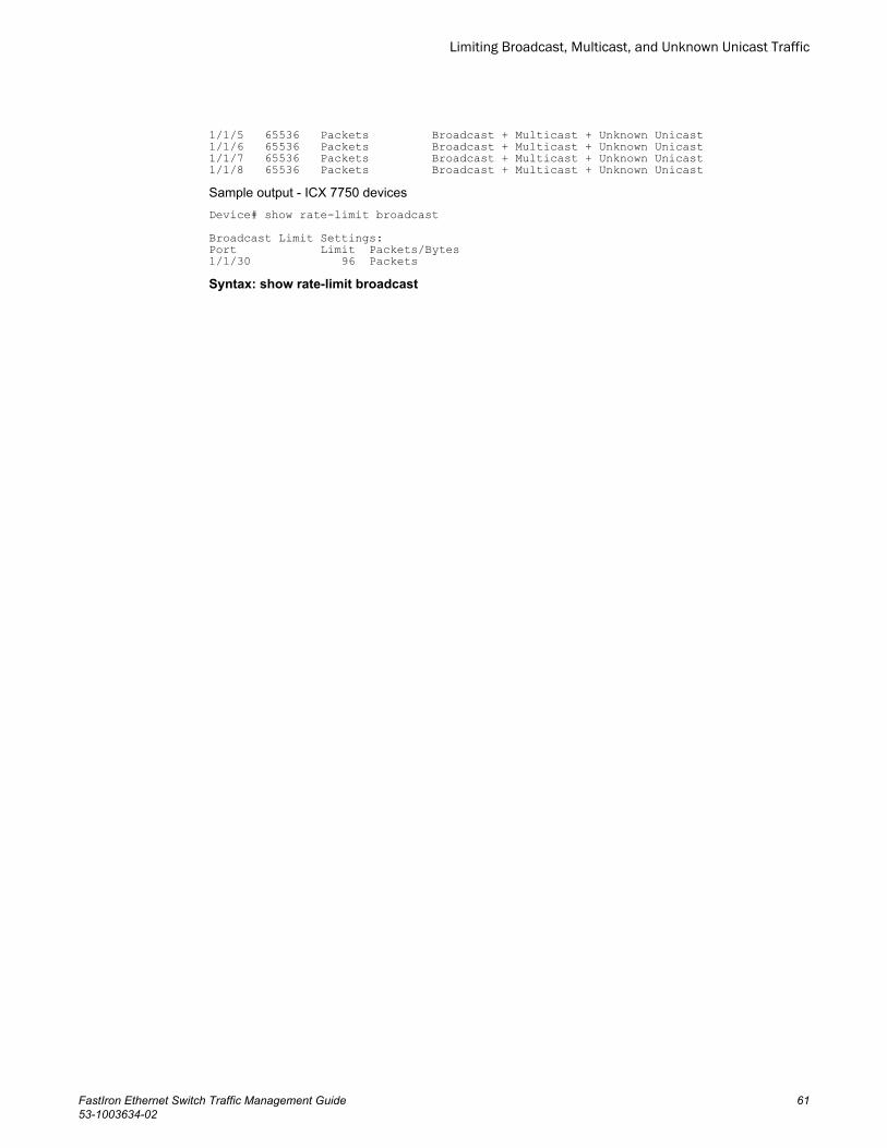
1/1/5 65536 Packets Broadcast + Multicast + Unknown Unicast1/1/6 65536 Packets Broadcast + Multicast + Unknown Unicast1/1/7 65536 Packets Broadcast + Multicast + Unknown Unicast1/1/8 65536 Packets Broadcast + Multicast + Unknown UnicastSample output - ICX 7750 devicesDevice# show rate-limit broadcast Broadcast Limit Settings:Port Limit Packets/Bytes1/1/30 96 PacketsSyntax: show rate-limit broadcast
Limiting Broadcast, Multicast, and Unknown Unicast Traffic
FastIron Ethernet Switch Traffic Management Guide 6153-1003634-02

Viewing broadcast, multicast, and unknown unicast limits
62 FastIron Ethernet Switch Traffic Management Guide53-1003634-02

Traffic Policies
● Traffic policies overview.................................................................................................. 63● Maximum number of traffic policies supported on a device............................................ 65● ACL-based rate limiting using traffic policies.................................................................. 66● ACL statistics and rate limit counting.............................................................................. 71● Viewing traffic policies.....................................................................................................75● CPU rate imiting.............................................................................................................. 76
Traffic policies overviewThis chapter describes how traffic policies are implemented and configured on the FastIron devices.
Traffic policies are rules that define rate limits on packets permitted by ACLs. As traffic policies applyrate limits on specific interfaces using ACLs, this method is also called ACL-based rate limiting. Theprocess for applying a traffic policy to an interface involves:
1. Creating a traffic policy2. Adding a reference to the traffic policy in an ACL entry3. Binding the ACL associated with this ACL entry to an interface
Brocade devices use traffic policies for the following reasons:
• To rate limit inbound traffic• To count the packets and bytes per packet to which ACL permit or deny clauses are applied
Traffic policies consist of policy names and policy definitions:
• Traffic policy name - A string of up to eight alphanumeric characters that identifies individual trafficpolicy definitions.
• Traffic policy definition (TPD) - The command filter associated with a traffic policy name. A TPD candefine any one of the following:
‐ Rate limiting policy‐ ACL counting policy‐ Combined rate limiting and ACL counting policy (not applicable on ICX 6650 devices)
The maximum number of supported active TPDs is a system-wide parameter and depends on thedevice you are configuring. The total number of active TPDs cannot exceed the system maximum.Refer to “Maximum number of traffic policies supported on a device.”
When you apply a traffic policy to an interface, you do so by adding a reference to the traffic policy in anACL entry, instead of applying the individual traffic policy to the interface. The traffic policy becomes anactive traffic policy or active TPD when you bind its associated ACL to an interface.
To configure traffic policies for ACL-based rate limiting, refer to “Configuring ACL-based fixed ratelimiting” and “ACL-based adaptive rate limiting configuration”.
To configure traffic policies for ACL counting, refer to “Enabling ACL statistics.”
FastIron Ethernet Switch Traffic Management Guide 6353-1003634-02

Configuration notes and feature limitations for traffic policiesNote the following when configuring traffic policies:
• Traffic policies applies to IP ACLs only.• Traffic policies are supported on FastIron X Series devices, but not on the 10 Gbps Ethernet
interfaces of the SX-FI62XG and SX-FI42XG modules.• The maximum number of supported active TPDs is a system-wide parameter and depends on the
device you are configuring. The total number of active TPDs cannot exceed the system maximum.Refer to the “Maximum number of traffic policies supported on a device” section.
• You can reference the same traffic policy in more than one ACL entry within an ACL. For example,two or more ACL statements in ACL 101 can reference a TPD named TPD1.
• You can reference the same traffic policy in more than one ACL. For example, ACLs 101 and 102could both reference a TPD named TPD1.
• Rate limits and ACL counting are applied at the traffic policy level, and are cumulative across ACLsand ACL entries on which they are applied. However, they are not cumulative across port regions.
• For all types of rate limiting on Brocade ICX 6650 devices (ACL-based; Port-based; and Broadcast,unknown Unicast, and Multicast rate limiting), the minimum value is 125 packets and can beincreased in steps of 125 packets.
• To modify or delete an active traffic policy, you must first unbind the ACL that references the trafficpolicy.
• When you define a TPD (when you enter the traffic-policy command), explicit marking of CoSparameters, such as traffic class and 802.1p priority, are not available on the device. In the case ofa TPD defining rate limiting, the device re-marks CoS parameters based on the DSCP value in thepacket header and the determined conformance level of the rate limited traffic, as shown in thefollowing table.
CoS parameters for packets that use rate limiting traffic policiesTABLE 29
Packet conformance level Packet DSCP value Traffic class and 802.1p priority
0 (Green)
or
1 (Yellow)
0 - 7 0 (lowest priority queue)
8 - 15 1
16 - 23 2
24 - 31 3
32 - 39 4
40 - 47 5
48 - 55 6
56 - 63 7 (highest priority queue)
2 (Red) N/A 0 (lowest priority queue)
• When you define a TPD, reference the TPD in an ACL entry, and then apply the ACL to a VE in theLayer 3 router code, the rate limit policy is accumulative for all of the ports in the port region. If the
Configuration notes and feature limitations for traffic policies
64 FastIron Ethernet Switch Traffic Management Guide53-1003634-02

VE or VLAN contains ports that are in different port regions, the rate limit policy is applied per portregion.
For example, TPD1 has a rate limit policy of 600M and is referenced in ACL 101. ACL 101 is applied toVE 1, which contains ethernet ports 1/1/1 to 1/1/4. Because ethernet ports 1/1/1 and 1/1/2 are in adifferent port region than ports 1/1/3 and 1/1/4, the rate limit policy will be 600M for ports 1/1/1 and1/1/2, and 600M for ports 1/1/3 and 1/1/4.
Maximum number of traffic policies supported on a deviceThe maximum number of supported active traffic policies is a system-wide parameter and depends onthe device you are configuring, as follows:
• By default, up to 1024 active traffic policies are supported on Layer 2 switches. This value is fixed onLayer 2 switches and cannot be modified.
• For FastIron devices other than the FCX, the number of active traffic policies supported on Layer 3switches varies depending on the configuration and the available system memory. The default valueand also the maximum number of traffic policies supported on Layer 3 switches is 50.
• On FCX devices, up to 1024 active traffic policies are supported on Layer 3 switches. This is thedefault value as well as the maximum value.
• The maximum number of active TPDs (traffic policy definitions) supported by Brocade ICX 6650 is896.
NOTEOn FCX devices, by default 992 of the maximum of 1024 active traffic policies are applied. The other 32are reserved and the show traffic command returns zero references/bindings beyond the 992 trafficpolicies.The show default values command displays the maximum number of traffic conditioners thatcan be applied, in the hw-traffic-conditioner section of the results. The configurable tables and theirdefaults and maximum values can be obtained using the show default command.
Setting the maximum number of traffic policies supported on a Layer 3device
NOTEThis configuration is supported on FastIron devices with the exception of the FCX and ICX 6650platforms. Setting the system-max for traffic policies is not required on FCX platforms as the defaultnumber of traffic policies is also the maximum number.
If desired, you can adjust the maximum number of active traffic policies that a Layer 3 device willsupport. To do so, enter commands such as the following at the global CONFIG level of the CLI.Device(config)#system-max hw-traffic-conditioner 25Device(config)#write memoryDevice(config)#reload
NOTEYou must save the configuration and reload the software to place the change into effect.
Syntax: [no] system-max hw-traffic-conditioner num
Maximum number of traffic policies supported on a device
FastIron Ethernet Switch Traffic Management Guide 6553-1003634-02

The num variable is a value from 0 through n, where 0 disables hardware resources for traffic policies,and n is a number up to 50. The maximum number you can configure depends on the configurationand available memory on your device. If the configuration you enter causes the device to exceed theavailable memory, the device rejects the configuration and displays a warning message on theconsole.
NOTEBrocade does not recommend setting the system maximum for traffic policies to 0 (zero), because thisrenders traffic policies ineffective.
ACL-based rate limiting using traffic policiesACL-based rate limiting provides the facility to limit the rate for IP traffic that matches the permitconditions in extended IP ACLs. This feature is available in the Layer 2 and Layer 3 code.
To configure ACL-based rate limiting, you create individual traffic policies , and then reference thetraffic policies in one or more ACL entries (also called clauses or statements). The traffic policiesbecome effective on ports to which the ACLs are bound.
When you configure a traffic policy for rate limiting, the device automatically enables rate limitcounting , similar to the two-rate three-color marker (trTCM) mechanism described in RFC 2698 foradaptive rate limiting, and the single-rate three-color marker (srTCM) mechanism described in RFC2697 for fixed rate limiting. This feature counts the number of bytes and trTCM or srTCM conformancelevel per packet to which rate limiting traffic policies are applied. Refer to ACL statistics and rate limitcounting on page 71.
You can configure ACL-based rate limiting on the following interface types:
• Physical Ethernet interfaces• Virtual interfaces• Trunk ports• Specific VLAN members on a port (refer to "Applying an IPv4 ACL to specific VLAN members on a
port (Layer 2 devices only)" section in the FastIron Ethernet Switch Security Configuration Guide ).• A subset of ports on a virtual interface (refer to "Applying an IPv4 ACL to a subset of ports on a
virtual interface (Layer 3 devices only)" section in the FastIron Ethernet Switch SecurityConfiguration Guide ).
Support for fixed rate limiting and adaptive rate limitingFastIron devices support the following types of ACL-based rate limiting:
• Fixed rate limiting - Enforces a strict bandwidth limit. The device forwards traffic that is within thelimit but either drops all traffic that exceeds the limit, or forwards all traffic that exceeds the limit atthe lowest priority level, according to the action specified in the traffic policy.
• Adaptive rate limiting - Enforces a flexible bandwidth limit that allows for bursts above the limit. Youcan configure adaptive rate limiting to forward traffic, modify the IP precedence of and forwardtraffic, or drop traffic based on whether the traffic is within the limit or exceeds the limit.
ACL-based rate limiting using traffic policies
66 FastIron Ethernet Switch Traffic Management Guide53-1003634-02

Configuring ACL-based fixed rate limitingUse the procedures in this section to configure ACL-based fixed rate limiting. Before configuring thisfeature, see what to consider in the “Configuration notes and feature limitations for traffic policies”section.
Fixed rate limiting enforces a strict bandwidth limit. The port forwards traffic that is within the limit. If theport receives more than the specified number of fragments in a one-second interval, the device eitherdrops or forwards subsequent fragments in hardware, depending on the action you specify.
To implement the ACL-based fixed rate limiting feature, first create a traffic policy, and then referencethe policy in an extended ACL statement. Lastly, bind the ACL to an interface. Complete the followingsteps.
1. Create a traffic policy. Enter a command such as the following.Device(config)#traffic-policy TPD1 rate-limit fixed 100 exceed-action drop
2. Create an extended ACL entry or modify an existing extended ACL entry that references the trafficpolicy. Enter a command such as the following.Device(config)#access-list 101 permit ip host 10.10.12.2 any traffic-policy TPD1
3. Bind the ACL to an interface. Enter commands such as the following.Device(config)#interface ethernet 1/1/5Device(config-if-31000-1/1/5)#ip access-group 101 in Device(config-if-e1000-1/1/5)#exitThe previous commands configure a fixed rate limiting policy that allows port 1/1/5 to receive amaximum traffic rate of 100 kbps (100 pkts/s for ICX 6650 devices). If the port receives additional bitsduring a given one-second interval, the port drops the additional inbound packets that are receivedwithin that one-second interval.
Syntax: [no] traffic-policy traffic-policy-def rate-limit fixed cir-value exceed-action drop [ count ]
Syntax: [no] traffic-policy traffic-policy-def rate-limit fixed cir-value exceed-action permit-at-low-pri [ count | remark-cos [ count ] ]
Syntax: access-list num {permit | deny.... } traffic policy TPDname
Syntax: [no] ip access-group num in
NOTEFor brevity, some parameters were omitted from the access-list syntax.
The software allows you to add a reference to a non-existent TPD in an ACL statement and to bindthat ACL to an interface. The software does not issue a warning or error message for non-existentTPDs.
Use the no form of the command to delete a traffic policy definition. Note that you cannot delete atraffic policy definition if it is currently in use on a port. To delete a traffic policy, first unbind theassociated ACL.
The TPDname variable is the name of the traffic policy definition. This value can be eight or feweralphanumeric characters.
The rate-limit fixed cir-value parameter specifies that the traffic policy will enforce a strict bandwidth.The cirvalue variable is the committed information rate in kbps. This value can be from 64 through1,000,000 Kbps.
NOTEFor ICX 6650 devices, the cir-value variable is the committed information rate in packets per second.This value can be from 125 through15,000,000 packets per second.
Configuring ACL-based fixed rate limiting
FastIron Ethernet Switch Traffic Management Guide 6753-1003634-02

The exceed-action actionparameter specifies the action to be taken when packets exceed theconfigured committed information rate (CIR) value. Refer to the “Specifying the action to be takenfor packets that are over the limit” section.
The remark-cos parameter sets 802.1p priority of the dropped packet to 0. If the option is specified,then the COS/PCP field value set to 0 for the low priority traffic for any packet exceeding the rate-limit set by the traffic policy. If the option is not used, there is no change in the existing behavior.
The count parameter is optional and enables ACL counting. Refer to the “ACL statistics and ratelimit counting” section.
ACL-based adaptive rate limiting configurationAdaptive rate limiting enforces a flexible bandwidth limit. The port forwards traffic that is within thelimit. If the port receives more than the specified number of fragments in a one-second interval, thedevice either drops or forwards subsequent fragments in hardware, depending on the exceed actionyou specify.
Use the procedures in this section to configure ACL-based adaptive rate limiting. Before configuringthis feature, see what to consider in the “Configuration notes and feature limitations for traffic policies”section.
The following table lists the configurable parameters for ACL-based adaptive rate limiting.
ACL based adaptive rate limiting parameters TABLE 30
Parameter Definition
Committed InformationRate (CIR)
The guaranteed kilobit (packets per second in ICX 6650 devices) rate of inbound trafficthat is allowed on a port.
Committed Burst Size(CBS)
The number of bytes per second (packets per second in ICX 6650 devices) allowed in aburst before some packets will exceed the committed information rate. Larger bursts aremore likely to exceed the rate limit. The CBS must be a value greater than zero (0).Brocade recommends that this value be equal to or greater than the size of the largestpossible IP packet in a stream.
Peak Information Rate(PIR)
The maximum kilobit (packets per second in ICX 6650 devices) rate for inbound trafficon a port. The PIR must be equal to or greater than the CIR.
Peak Burst Size (PBS) The number of bytes per second (packets per second in ICX 6650 devices) allowed in aburst before all packets will exceed the peak information rate. The PBS must be a valuegreater than zero (0). Brocade recommends that this value be equal to or greater thanthe size of the largest possible IP packet in the stream.
If a port receives more than the configured bit or byte (packets per second in ICX 6650 devices) rate ina one-second interval, the port will either drop or forward subsequent data in hardware, depending onthe action you specify.
Configuring ACL-based adaptive rate limiting
To implement the ACL-based adaptive rate limiting feature, first create a traffic policy, and thenreference the policy in an extended ACL statement. Lastly, bind the ACL to an interface. Complete thefollowing steps.
ACL-based adaptive rate limiting configuration
68 FastIron Ethernet Switch Traffic Management Guide53-1003634-02

1. Create a traffic policy. Enter a command such as the following.Device(config)#traffic-policy TPDAfour rate-limit adaptive cir 10000 cbs 1600 pir 20000 pbs 4000 exceed-action drop
2. Create a new extended ACL entry or modify an existing extended ACL entry that references thetraffic policy. Enter a command such as the following.Device(config)#access-list 104 permit ip host 10.10.12.2 any traffic-policy TPDAfour
3. Bind the ACL to an interface. Enter commands such as the following.Device(config)#interface ethernet 1/1/7Device(config-if-e1000-1/1/7)#ip access-group 104 inDevice(config-if-e1000-1/1/7)#exitThe previous commands configure an adaptive rate limiting policy that enforces a guaranteedcommitted rate of 10000 kbps on port 1/1/7 and allows bursts of up to 1600 bytes. It also enforces apeak rate of 20000 kbps and allows bursts of 4000 bytes above the PIR limit. If the port receivesadditional bits during a given one-second interval, the port drops all packets on the port until the nextone-second interval starts.
NOTEOn ICX 6650 devices, rate-limiting is packet-based.
Syntax: [no] traffic-policy traffic-policy-def rate-limit adaptive cir cir-value cbs cbs-value pir pir-value pbs pbs-value exceed-action drop [ count ]
Syntax: [no] traffic-policy traffic-policy-def rate-limit adaptive cir cir-value cbs cbs-value pir pir-value pbs pbs-value exceed-action permit-at-low-pri [ count | remark-cos [ count ] ]
Syntax: access-list num { permit | deny.... } traffic policy TPDname
Syntax: [no] ip access-group num in
NOTEFor brevity, some parameters were omitted from the access-list syntax.
The software allows you to add a reference to a non-existent TPD in an ACL statement and to bindthat ACL to an interface. The software does not issue a warning or error message for non-existentTPDs.
Use the no form of the command to delete a traffic policy definition. Note that you cannot delete atraffic policy definition if it is currently in use on a port. To delete a traffic policy, first unbind theassociated ACL.
The TPDname variable is the name of the traffic policy definition. This value can be eight or feweralphanumeric characters.
The rate-limit adaptive cir parameter specifies that the policy will enforce a flexible bandwidth limitthat allows for bursts above the limit. The cir-value variable is the committed information rate in kbpson all the other supported platform except on ICX 6650 devices, where it is packets/second. Refer tothe ACL based adaptive rate limiting parameters table.
The cbs cbs-value parameter is the committed burst size in bytes on all supported platforms excepton ICX 6650 devices, where it is in packets.
The pir pir-value parameter is the peak information rate in kbps on all supported platforms except onICX 6650 devices, where it is packets/second.
The pbs pbs-value parameter is the peak burst size in bytes on all supported platforms except onICX 6650 devices, where it is in packets.
The exceed-action parameter specifies the action to be taken when packets exceed the configuredvalues. Refer to the “Specifying the action to be taken for packets that are over the limit” section.
Traffic Policies
FastIron Ethernet Switch Traffic Management Guide 6953-1003634-02

The count parameter is optional and enables ACL counting. Refer to the “ACL statistics and ratelimit counting” section.
Inspecting the 802.1p bit in the ACL for adaptive rate limiting
You can configure the Brocade device to rate limit traffic for a specified 802.1p priority value. To do so,complete the following configuration steps.
1. Create an adaptive rate limiting traffic policy. Enter a command such as the following:Device(config)#traffic-policy adap rate-limit adaptive cir 1000 cbs 1000 pir 2000 pbs 10000 exceed-action drop
2. Create an IPv4 extended ACL or IPv6 ACL that includes the traffic policy and 802.1p prioritymatching value. Enter a command such as the following:Device(config)#access-list 136 permit ip any any 802.1p-priority matching 3traffic-policy adap
3. Bind the ACL to an interface. Enter commands such as the following,.Device(config)#interface ethernet 1/1/7Device(config-if-1/1/7)#ip access-group 136 inDevice(config-if-1/1/7)#exitUse the show access-list accounting command to view accounting statistics. For moreinformation, refer to the “Viewing ACL and rate limit counters” section.
Specifying the action to be taken for packets that are over the limitYou can specify the action to be taken when packets exceed the configured CIR value for fixed ratelimiting, or the CIR, CBS, PIR, and PBS values for adaptive rate limiting. You can specify one of thefollowing actions:
• Drop packets that exceed the limit.• Permit packets that exceed the limit and forward them at the lowest priority level.
Dropping packets that exceed the limit
The ultimate action that a device can take on a packet is to drop the packet. You can apply the dropaction on packets that exceed the rate limit in both fixed rate limiting and adaptive rate limiting trafficpolicies. In fixed rate limiting policies, a packet is dropped only when the packet rate exceeds the CIRlimit. Whereas, in adaptive rate limiting policies, a packet is dropped only when the packet rateexceeds PIR limit + PBS within one second.
This section shows some example configurations and provides the CLI syntax for configuring a port todrop packets that exceed the configured limits for rate limiting.
The following example shows a fixed rate limiting configuration:
Device(config)#traffic-policy TPD1 rate-limit fixed 10000 exceed-action dropThe command sets the fragment threshold at 10,000 packets per second. If the port receives morethan 10,000 packets in a one-second interval, the device drops the excess fragments.
Syntax: [no] traffic-policy traffic-policy-def rate-limit fixed cir-value exceed-action drop [ count ]
Syntax: [no] traffic-policy traffic-policy-def rate-limit fixed cir-value exceed-action permit-at-low-pri [ count | remark-cos [ count ] ]
The following example shows an adaptive rate limiting configuration.Device(config)#traffic-policy TPDA4 rate-limit adaptive cir 10000 cbs 1600 pir 20000 pbs 4000 exceed-action drop
Inspecting the 802.1p bit in the ACL for adaptive rate limiting
70 FastIron Ethernet Switch Traffic Management Guide53-1003634-02

The command configures an adaptive rate limiting policy that enforces a guaranteed committed rate of10000 kbps (10000 pkts/s in ICX 6650 devices) and allows bursts of up to 1600 bytes (1600 packets inICX 6650 devices). It also enforces a peak rate of 20000 kbps (20000 pkts/s in ICX 6650 devices) andallows bursts of 4000 bytes (4000 packets in ICX 6650 devices) above the PIR limit. If the port receivesadditional bits during a given one-second interval, the port drops all packets on the port until the nextone-second interval starts.
Syntax: [no] traffic-policy traffic-policy-def rate-limit adaptive cir cir-value cbs cbs-value pir pir-value pbs pbs-value exceed-action drop [ count ]
Syntax: [no] traffic-policy traffic-policy-def rate-limit adaptive cir cir-value cbs cbs-value pir pir-value pbs pbs-value exceed-action permit-at-low-pri [ count | remark-cos [ count ] ]
Permitting packets that exceed the limit
This section shows some example configurations and provides the CLI syntax for configuring a port topermit packets that exceed the configured limit for rate limiting.
The following example shows a fixed rate limiting configuration.Device(config)#traffic-policy TPD1 rate-limit fixed 10000 exceed-action permit-at-low-priThe command sets the fragment threshold at 10,000 packets per second. If the port receives more than10,000 packets in a one-second interval, the device takes the specified action. The action specified withthis command is to permit excess fragments and forward them at the lowest priority level.
Syntax: [no] traffic-policy traffic-policy-def rate-limit fixed cir-value exceed-action drop [ count ]
Syntax: [no] traffic-policy traffic-policy-def rate-limit fixed cir-value exceed-action permit-at-low-pri[ count | remark-cos [ count ] ]
The following example shows an adaptive rate limiting configuration.Device(config)#traffic-policy TPDA4 rate-limit adaptive cir 10000 cbs 1600 pir 20000 pbs 4000 exceed-action permit-at-low-priThe command configures an adaptive rate limiting policy that enforces a guaranteed committed rate of10000 kbps (10000 pkts/s in ICX 6650 devices) and allows bursts of up to 1600 bytes (1600 packets inICX 6650 devices). It also enforces a peak rate of 20000 kbps (20000 pkts/s in ICX 6650 devices) andallows bursts of 4000 bytes (4000 packets in ICX 6650 devices) above the PIR limit. If the port receivesadditional bits during a given one-second interval, the port permits all packets on the port and forwardsthe packets at the lowest priority level.
Syntax: [no] traffic-policy traffic-policy-def rate-limit adaptive cir cir-value cbs cbs-value pir pir-value pbs pbs-value exceed-action drop [ count ]
Syntax: [no] traffic-policy traffic-policy-def rate-limit adaptive cir cir-value cbs cbs-value pir pir-value pbs pbs-value exceed-action permit-at-low-pri [ count | remark-cos [ count ] ]
ACL statistics and rate limit countingACL statistics , also called ACL counting , enables the Brocade device to count the number of packetsand the number of bytes per packet to which ACL filters are applied.
Rate limit counting counts the number of bytes and the conformance level per packet to which ratelimiting traffic policies are applied. The device uses the counting method similar to the two-rate three-color marker (trTCM) mechanism described in RFC 2698 for adaptive rate limiting, and the single-ratethree-color marker (srTCM) mechanism described in RFC 2697 for fixed rate limiting. Rate limit
Permitting packets that exceed the limit
FastIron Ethernet Switch Traffic Management Guide 7153-1003634-02

counting is automatically enabled when a traffic policy is enforced (active). You can view thesecounters using the show commands listed in Viewing traffic policies on page 75.
Enabling ACL statistics
NOTEACL statistics and ACL counting are used interchangeably throughout this chapter and mean thesame thing.
Use the procedures in this section to configure ACL statistics. Before configuring ACL statistics, seewhat to consider in Configuration notes and feature limitations for traffic policies on page 64.
To enable ACL statistics on a device, first create a traffic policy , and then reference the traffic policy inan extended ACL entry. Lastly, bind the ACL to an interface. The ACL counting policy becomeseffective on ports to which the ACLs are bound.
You also can enable ACL statistics when you create a traffic policy for rate limiting. Refer to EnablingACL statistics with rate limiting traffic policies on page 73.
Complete the following steps to implement the ACL statistics feature.
1. Create a traffic policy. Enter a command such as the following.
device(config)#traffic-policy TPD5 count2. Create an extended ACL entry or modify an existing extended ACL entry that references the traffic
policy definition. Enter a command such as the following.device(config)#access-list 101 permit ip host 10.10.12.2 any traffic-policy TPD5
3. Bind the ACL to an interface. Enter commands such as the following.device(config)#interface ethernet 1/1/4device(config-if-e1000-1/1/4)#ip access-group 101 indevice(config-if-e1000-1/1/4)#exitThe previous commands configure an ACL counting policy and apply it to port 1/1/4. Port 1/1/4counts the number of packets and the number of bytes on the port that were permitted or denied byACL filters.
Syntax: [no] traffic-policy TPDname count
Syntax: ip access-list extended 101
Device (config-std-nacl)# { permit | deny } protocol source destination traffic-policy TPDname
Syntax: [no] ip access-group num in
NOTEFor brevity, some parameters were omitted from the access-list syntax.
The software allows you to add a reference to a non-existent TPD in an ACL statement and to bindthat ACL to an interface. The software does not issue a warning or error message for non-existentTPDs.
Use the no form of the command to delete a traffic policy definition. Note that you cannot delete atraffic policy definition if it is currently in use on a port. To delete a traffic policy, first unbind theassociated ACL.
The TPDname variable is the name of the traffic policy definition. This value can be eightalphanumeric characters or fewer.
Enabling ACL statistics
72 FastIron Ethernet Switch Traffic Management Guide53-1003634-02

Enabling ACL statistics with rate limiting traffic policiesThe configuration example in the section “Enabling ACL statistics” shows how to enable ACL countingwithout having to configure parameters for rate limiting. You also can enable ACL counting whiledefining a rate limiting traffic policy, as illustrated in the following configuration examples.
To enable ACL counting while defining traffic policies for fixed rate limiting, enter commands such asthe following at the global config level of the CLI.Device(config)#traffic-policy TPD1 rate-limit fixed 1000 countDevice(config)#traffic-policy TPD2 rate-limit fixed 10000 exceed-action drop countSyntax: [no] traffic-policy traffic-policy-def rate-limit fixed cir-value exceed-action drop [ count ]
Syntax: [no] traffic-policy traffic-policy-def rate-limit fixed cir-value exceed-action permit-at-low-pri[ count | remark-cos [ count ] ]
See the FastIron Command Reference for a description of the traffic-policy rate-limit fixed command.
To enable ACL counting while defining traffic policies for adaptive rate limiting, enter commands suchas the following at the global config level of the CLI.Device(config)#traffic-policy TPDA4 rate-limit adaptive cir 10000 cbs 1600 pir 20000 pbs 4000 countDevice(config)#traffic-policy TPDA5 rate-limit adaptive cir 10000 cbs 1600 pir 20000 pbs 4000 exceed-action permit-at-low-pri countSyntax: [no] traffic-policy traffic-policy-def rate-limit adaptive cir cir-value cbs cbs-value pir pir-value pbs pbs-value exceed-action drop [ count ]
Syntax: [no] traffic-policy traffic-policy-def rate-limit adaptive cir cir-value cbs cbs-value pir pir-value pbs pbs-value exceed-action permit-at-low-pri [ count | remark-cos [ count ] ]
See the FastIron Command Reference for a description of the traffic-policy rate-limit adaptivecommand.
Viewing ACL and rate limit countersWhen ACL counting is enabled on the Brocade device, you can use show commands to display thetotal packet count and byte count of the traffic filtered by ACL statements. The output of the showcommands also displays the rate limiting traffic counters, which are automatically enabled for active ratelimiting traffic policies.
Use either the show access-list accounting traffic-policy command or the show statistics traffic-policy command to display ACL and traffic policy counters. The output of these commands is identical.
NOTEIn the SX-FI48GPP module only, the output of these commands is identical with one exception. WhenACL counting is shown by show statistics traffic-policy , the Packet Count is not supported anddisplays "N/A".
The following example shows the output from the show access-list accounting command.
Device#show access-list accounting traffic-policy g_voipTraffic Policy - g_voip:General Counters:Port Region# Byte Count Packet Count------------------ -------------------- ----------------------7 (4/1 - 4/12) 85367040 776064All port regions 84367040 776064Rate Limiting Counters:Port Region# Green Conformance Yellow Conformance Red Conformance------------------ ------------------ ------------------ ------------------
Enabling ACL statistics with rate limiting traffic policies
FastIron Ethernet Switch Traffic Management Guide 7353-1003634-02

7 (4/1 - 4/12) 329114195612139520 37533986897781760 0All port regions 329114195612139520 37533986897781760 0The following example shows the output on an ICX 6650 device.
Device#show access-list accounting traffic-policy tf125cTraffic Policy tf125c:Port Regions:---------------0 : 1/1/1-1/1/56, 1/3/1-1/3/8, 1/2/1-1/2/4General Counters:Port Region# Byte Count Packet Count---------------- -------------------- --------------------7 (4/1 - 4/12) 85367040 776064All port regions 84367040 776064Rate Limiting Counters (in Packets):Port Region# Green Conformance Yellow Conformance Red Conformance------------ ----------------- ------------------ ------------7 (4/1 - 4/12) 551475 224589 0All port regions 551475 224589 0The following example shows the output on an ICX 7750 device.Device#show statistics traffic-policy abcTraffic Policy tf125c: General Counters: Port Region# Byte Count Packet Count ---------------- -------------------- -------------------- 0 235400192 1839051 All port regions 235400192 1839051
Rate Limiting Counters (in bytes): Port Region# Green/Yellow Conformance Red Conformance -------------- --------------------------- -------------------- 0 225023872 10376320 All port regs 225023872 10376320Syntax: show access-list accounting traffic-policy [ TPDname ]
or
Syntax: show statistics traffic-policy [ TPDname ]
The TPDname variable is the name of the traffic policy definition for which you want to display ACLand traffic policy counters.
The following table explains the output of the show access-list accounting traffic-policy and showstatistics traffic-policy commands.
ACL and rate limit counting statistics TABLE 31
Parameter Description
Traffic Policy The name of the traffic policy.
General Counters
Port Region # The port region to which the active traffic policy applies.
Byte Count The number of bytes (packets in ICX 6650 devices) that were filtered (matched ACLclauses).
Packet Count The number of packets that were filtered (matched ACL clauses).
Rate Limiting Counters
Traffic Policies
74 FastIron Ethernet Switch Traffic Management Guide53-1003634-02

ACL and rate limit counting statistics (Continued)TABLE 31
Parameter Description
Port Region# The port region to which the active traffic policy applies.
Green Conformance The number of bytes (packets in ICX 6650 devices) that did not exceed the CIR packetrate.
Yellow Conformance The number of bytes (packets in ICX 6650 devices) that exceeded the CIR packet rate.
Red Conformance The number of bytes (packets in ICX 6650 devices) that exceeded the PIR packet rate.
Clearing ACL and rate limit countersThe Brocade device keeps a running tally of the number of packets and the number of bytes per packetthat are filtered by ACL statements and rate limiting traffic policies. You can clear these accumulatedcounters, essentially resetting them to zero. To do so, use either the clear access-list accountingtraffic-policy command or the clear statistics traffic-policy command.
To clear the counters for ACL counting and rate limit counting, enter commands such as the following.Device(config)#clear access-list accounting traffic-policy CountOneDevice(config)#clear statistics traffic-policy CountTwoSyntax: clear access-list accounting traffic-policy TPDname
or
Syntax: clear statistics traffic-policy TPDname
The TPDname variable is the name of the traffic policy definition for which you want to clear trafficpolicy counters.
Viewing traffic policies
To view traffic policies that are currently defined on the Brocade device, enter the show traffic-policycommand. The following example shows displayed output. The following table explains the output of theshow traffic-policy command.
Device#show traffic-policy t_voipTraffic Policy - t_voip:Metering Enabled, Parameters: Mode: Adaptive Rate-Limiting cir: 100 kbps, cbs: 2000 bytes, pir: 200 kbps, pbs: 4000 bytesCounting Not EnabledNumber of References/Bindings:1Sample output from an ICX 6650 device:
Device#show traffic-policy t_voipTraffic Policy - t_voip:Metering Enabled, Parameters:Mode: Adaptive Rate-Limitingcir: 100 Pkts/s, cbs: 2000 Pkts, pir: 200 Pkts/s, pbs: 4000 PktsCounting Not Enabled
Clearing ACL and rate limit counters
FastIron Ethernet Switch Traffic Management Guide 7553-1003634-02

Syntax: show traffic-policy TPDname
To display all traffic policies, enter the show traffic-policy command without entering a TPD name.
Traffic policy information TABLE 32
Parameter Description
Traffic Policy The name of the traffic policy.
Metering Shows whether or not rate limiting was configured as part of the traffic policy:
• Enabled - The traffic policy includes a rate limiting configuration.• Disabled - The traffic policy does not include a rate limiting configuration.
Mode If rate limiting is enabled, this field shows the type of metering enabled on the port:
• Fixed Rate-Limiting• Adaptive Rate-Limiting
cir The committed information rate, in kbps (pkts/s in ICX 6650 devices), for the adaptive ratelimiting policy.
cbs The committed burst size, in bytes (packets in ICX 6650 devices) per second, for theadaptive rate- imiting policy.
pir The peak information rate, in kbps (pkts/s in ICX 6650 devices), for the adaptive ratelimiting policy.
pbs The peak burst size, in bytes (packets in ICX 6650 devices) per second, for the adaptiverate limiting policy.
Counting Shows whether or not ACL counting was configured as part of the traffic policy:
• Enabled - Traffic policy includes an ACL counting configuration.• Not Enabled - Traffic policy does not include an ACL traffic counting configuration.
Number ofReferences/Bindings NOTE
This field does not apply to FastIron X and ICX 6650 devices.
The number of port regions to which this traffic policy applies. For example, if the trafficpolicy is applied to a trunk group that includes ethernet ports 1/9/9, 1/9/10, 1/9/11, and1/9/12, the value in this field would be 2, because these four trunk ports are in two differentport regions.
CPU rate imitingUnnecessary traffic to the switch CPU lowers the efficiency of the CPU and delays handling of othertraffic that requires processing. CPU rate limiting is a CPU protection scheme which limits certaintraffic types.
CPU rate imiting
76 FastIron Ethernet Switch Traffic Management Guide53-1003634-02

CPU rate limiting identifies the traffic type and assigns a maximum rate limit to the traffic type. Thetraffic types which are subjected to rate limiting include broadcast ARP and other exceptions, such asTTL exceed, IP MTU failed, reverse path check failed, IP fragments, and unsupported tunneling. Eachof these types is rate-limited individually.
The following table shows the rate limits for each rate-limited packet type and shows which platforms onwhich each rate limit applies. These rates cannot be configured by users currently.
CPU rate limits for packet type and applicable platforms TABLE 33
Packet type Rate limit in packets persecond
Applicable platforms
ARP 6000 All
IP TTL exceed, or
Reverse path check failed
150 All
IP MTU exceed,
IP tunnel-terminated packets which are fragmented or hasoptions, or
IP tunnel-terminated packets with unsupported GRE tunnelheader
3000 All
IP Unicast packets mirrored to CPU due to ICMP redirect 100 All
Bridge packets forward to CPU 5000 FCX and ICX
All currently supported FastIron devices support the CPU rate-limiting feature. However, on the FSXdevices, only the following modules support this feature:
• SX-FI-24GPP• SX-FI-24HF• SX-FI-2XG• SX-FI-8XG• SX-FI48GPP
Traffic Policies
FastIron Ethernet Switch Traffic Management Guide 7753-1003634-02

CPU rate imiting
78 FastIron Ethernet Switch Traffic Management Guide53-1003634-02

ICX 7750 Flow Control and Buffer Management
● Priority flow control .........................................................................................................79● Configuring priority flow control.......................................................................................80● Configuring priority flow control on a port........................................................................80● Configuring priority flow control on a range of ports........................................................81● Packet buffer management............................................................................................. 81
Priority flow controlBrocade's priority flow control (PFC) feature prevents frame loss from congestion by pausing trafficbased on the congested priority without affecting the traffic of uncongested priorities.
Flow control enables feedback from a receiver to its sender to communicate buffer availability. PFCimplements IEEE 802.1Qbb PFC on Brocade ICX 7750 devices, supporting eight priorities and fourpriority groups (PGs) that can be subject to flow control independently. You can configure PGs forpriority flow control and ingress buffer management.
Because multiple priorities can be mapped to a single PG, congestion on one priority in a PG mightgenerate a pause, stopping transmission of all priorities in the PG. Therefore, it is important to create acustom priority-to-PG map to meet your application needs, using either PFC pause honoring or PFCpause transmission.
PFC pause honoring
• The MAC decodes the class enable vector field to extract the priorities and pause timer value fromthe packet.
• The per priority XOFF/XON status is passed to the pausing logic to pause/resume packet schedulingto the corresponding queue of the egress port.
PFC pause transmission
• Each priority can be mapped to a PG. The mapping is configurable.• When buffer threshold of a PG exceeds XOFF value, a PFC pause frame is sent. The pause frame is
encoded with all priorities that belong to the PG in class enable vector.
A receiver using PFC must predict the potential for buffer exhaustion for a PG and respond bygenerating an explicit PAUSE frame for that class when that condition arises. At any time the receivermust have enough ingress buffers available to store any packet that might be in flight while the PAUSEframe travels back to the sender and gets processed there. In ICX 7750 devices, the number of ingressbuffers is set automatically according to the port speed when PFC is enabled.
NOTEConfiguring PFC commands interrupts traffic temporarily.
You can configure the qos priority-to-pg command to change the default priority to PG mapping. Seethe description of the qos priority-to-pg command for more information on the default mapping.
By default, the Brocade ICX 7750 device boots up with tail-drop mode, which means that packets aredropped at the egress queues during congestion. By default, all ports honor IEEE 802.3X pause.However, when transmission of the 802.3x pause is disabled, PFC is also disabled. You can configurethe symmetrical-flow-control enable command to enable the transmission of the 802.3x pause. See
FastIron Ethernet Switch Traffic Management Guide 7953-1003634-02

the description of the symmetrical-flow-control enable command for more information onsymmetrical flow control (SFC).
NOTE
Enabling flow control on ports that have auto-neg enabled causes flap because the port pausecapabilities must be advertised and negotiated again with peer.
Ports that have auto-neg disabled do not experience flap.
In FastIron Release 08.0.20 and later releases, the following conditions apply on ICX 7750 devices:
• PFC and SFC are not supported for ports across stack units.• SFC is not supported for ports across master and slave packet-processor (pp) devices in
ICX7450-48 units.
In FastIron Release 08.0.20 and later releases, the following conditions apply on ICX 7450 devices:
• PFC is not supported.• SFC is not supported for ports across stack units, or for ports across master and slave packet-
processor (pp) devices in ICX7450-48 units.
Configuring priority flow controlEnables priority flow control (PFC) globally and for a priority group.
1. Enable PFC globally.Device(config)# priority-flow-control enable
2. Enable PFC for priority group (PG) 0.Device(config)# priority-flow-control 0
Configuring priority flow control on a portEnables priority flow control (PFC) for a priority group on a port.
PFC must be enabled on at least one priority group (PG) before you can configure the priority-flow-control enable command on an interface.
1. Enable PFC globally.Device(config)# priority-flow-control enable
2. Enable PFC for PG 0.Device(config)# priority-flow-control 0
3. Enable interface configuration mode.Device(config)# interface ethernet 1/1/1
4. Enable PFC on the interface.Device(config-if-e10000-1/1/1)# priority-flow-control enable
Configuring priority flow control
80 FastIron Ethernet Switch Traffic Management Guide53-1003634-02

Configuring priority flow control on a range of portsEnables priority flow control (PFC) for a priority group on a range of ports.
PFC must be enabled on at least one priority group (PG) before you can configure the priority-flow-control enable command on an interface.
1. Enter configuration mode.Device# configure terminal
2. Enter interface configuration mode for ports in the range you want to enable PFCDevice(config)#interface ethernet 1/1/42 ethernet 1/1/43Enables PFC for the ports in the range specified.
3. Enable PFC globally as described in the “Configuring priority flow control“ section.4. Enable PFC on the required ports.
Device(config-mif-1/1/42-1/1/43)# priority-flow-control enableEnables PFC on the specified ports.
5. Display the PFC status for the ports in the range specified.Device(config)# show running interface ethernet 1/1/43 ethernet 1/1/42interface ethernet 1/1/42 priority-flow-control enable!interface ethernet 1/1/43 load-interval 30 priority-flow-control enable!Confirms that PFC is enabled on the range of ports specified.
Packet buffer managementIngress- and egress-buffer management as packet admission mechanisms.
On Brocade ICX 7750 devices, packet memory can support 960 Gbps bandwidth. The total packetmemory is 12M bytes. ICX 7750 devices run in cut-through mode, which means that cut-through eligiblepackets are not buffered. If a packet needs to be buffered, it is buffered after Layer 2 and 3 lookup.Packet priority is classified before buffering.
There are two independent packet admission mechanisms: ingress buffer management and egressbuffer management.
Ingress buffer management
• The ingress buffer mechanism determines whether a packet should be admitted into memory-basedon the state of available memory and the amount of buffer resources in use by the ingress portpriority group.
• It aims to support fair access to buffering resources while also enabling loss-less operation across anetwork.
• The memory is logically divided into three sections: guaranteed, shared, and headroom for flowcontrol in fly packets.
• Ingress buffer limits are automatically configured based on user configuration to support either loss-less or tail drop operation.
• You can configure the qos ingress-buffer-profile command to configure a share level, whichdetermines the maximum number of buffers a PG can use as a fraction of the total sharing pool. Forexample, if PG 0 is at level4, it can use up to 1/9 of the total sharing buffers in the sharing pool. Theactual number of buffers a PG can use depends on the number currently available in the system.See the description of the qos ingress-buffer-profile command for more information on ingressbuffer profiles.
Configuring priority flow control on a range of ports
FastIron Ethernet Switch Traffic Management Guide 8153-1003634-02

Egress buffer management
• The egress buffer mechanism tracks buffer utilization on a per egress port-priority basis. As theseaccounting structures reach the limit, packets that are destined to the congested egress port-priorityare tail-dropped.
• It aims to support fair access to the buffering resources among congested egress ports.• Any incoming packet is counted only once per egress port regardless of whether it is unicast or
multicast.• Memory is logically divided into two sections: guaranteed and shared.• You can configure the qos egress-buffer-profile command to configure a share level, which
determines the maximum number of buffers an egress queue can use as a fraction of the totalsharing pool. For example, if queue 4 is at level4, it can use up to 1/9 of the total sharing buffers inthe sharing pool. You can configure eight levels of sharing. The actual number of buffers a queuecan use depends on the number currently available in the system. See the description of the qosegress-buffer-profile command for more information on egress buffer profiles.
ICX 7750 Flow Control and Buffer Management
82 FastIron Ethernet Switch Traffic Management Guide53-1003634-02