
Traffic Light Control System Using Microcontroller
12
AL-Qadisiyah Journal of pure Science Vol.23 No. 2 Year 2018 269 Traffic Light Control System Using Microcontroller Rasha falah kadhem Rasha. kadhem@ qu.edu.iq Al-Qadisiyah University, College of Computer Science and Information Technology, Department of Multimedia Received:- 20/8/2017 Accepted:-23/1/2018 Abstract: Computing machines were always consided an attraction for the automation field of technology in both industrial and domestic products. For that reason, we should learn how to programed and used Microcontroller as a useful device. That led to more and more universities and colleges become interesting and starting to teach the microcontroller, especially Microchip PIC microcontrollers. This research an effort to design, programming and build a basic programmable traffic light control device for 4 tracks intersection.
Transcript of Traffic Light Control System Using Microcontroller
AL-Qadisiyah Journal of pure Science Vol.23 No. 2 Year 2018
269
Traffic Light Control System Using Microcontroller
Rasha falah kadhem
Rasha. kadhem@ qu.edu.iq
Al-Qadisiyah University, College of Computer Science and Information
Technology, Department of Multimedia
Received:- 20/8/2017 Accepted:-23/1/2018
Abstract: Computing machines were always consided an attraction for the automation field
of technology in both industrial and domestic products. For that reason, we should
learn how to programed and used Microcontroller as a useful device. That led to
more and more universities and colleges become interesting and starting to teach the
microcontroller, especially Microchip PIC microcontrollers. This research an effort to
design, programming and build a basic programmable traffic light control device for 4
tracks intersection.
AL-Qadisiyah Journal of pure Science Vol.23 No. 2 Year 2018
270
1. Defining of the Research: Creating a basic traffic signal
for four traffic track intersection,
three signals per track green,
yellow and red, using
microcontroller to get outputs of
five volts at specific times
according to the data specified in
the program, which will be used
to run the LEDs that represent the
different signals for each track.,
1.1 Preface and Research
Importance:
Computing machines were
always consided an attraction for
the automation field of technology
in both industrial and domestic
products. it is one of the
objectives of motivation to
develope the computing machines
and devices. but it change after
invention the first
microprocessor, it was hardly to
practically think of any of the
algorithms in reality to use
because of the size and power
consumption. These limitations
have been ended because the
availability of powerful
microprocessors and
microcontrollers. smaller size and
fast implementation and power
consumption with effective
computation are some of the
issues, which could further
increase expectations from
the computing machines.
microcontrollers had became an
integral part of all automatic and
semi-automatic machines,
especially Microchip PIC. Remote
controllers, hand-held
communication devices, dedicated
controllers that use it, have
certainly improved the functional,
operational and performance-
based specifications. The
architectural changes in
instrumentation and control
systems were and are dueto the
computing and communication
capability of the microcontroller
devices. For that reason, in the past
few years, more universities and
colleges became interested and
started to teach microcontroller,
especially the Microchip PIC
microcontrollers. Microchip designs
and manufactures several families
of 8-bit microcontrollers. Among
them, the PIC 16 family and the
P1C1H family are the two most
important families. The PIC 18
family was the Latest development
and has several advantages over
the PIC microcontroller family."
1.2 Research Objectives:
to learn how to programming and
using Microcontroller as a powerful
device, we chose to design and build
a basic traffic signal for four tracks
traffic intersection, three signals per
AL-Qadisiyah Journal of pure Science Vol.23 No. 2 Year 2018
271
track, green, yellow and red, using
microcontroller PIC16F84A to get
five volts outputs in a specific times
according to the data specified in the
program, which will be drive twelve
LEDs that represent the different
signals for each track.
2- Theoretical Framework: 2-1 Microcontroller vs Microprocessor:
Although processors are of great importance in digital-based systems, but they are relatively bag in size that are difficult to embed in the devices that we need to control, and
they have high capabilities that we often do not in need to for device-control purposes, which makes it very energy-consuming. These issues make using microprocessors for automation purposes is limited, which has led to design the microcontrollers as a tool beyond these limitations to make automation of types of device and equipment more efficiency.
The microcontroller provides, in a
simple form, all the main elements of
the microprocessor system on a
single chip. As a result, less difcu
lt applications can be designed
and built quickly and cheaply. A
working system can contain of a
microcontroller chip and just a few
external components for feeding data
and signals IN and OUT. They tend
to be used for control operations
requiring limited amounts of
memory but operating at high speed,
with external hardware attached only
as required by a specific application.
2-2 Microcontroller PIC:
PIC Microcontroller was
originally a design of the company
General Instruments. It was
intended for simple control
applications, the name - Peripheral
Interface Controller. In the 1970s,
General Instruments produced the
PIC 1650 and 1655 processors.
Although the design was
comparatively crude and
unconventional, it was completely
stand-alone, and contained some
important and forward-looking
features. The simple CPU was a RISC
structure, with a single Working
register and just 30 inst. The output
pins could source or sink much more
current than most other
microprocessors of the time.
Already the trademarks of the PIC
were emerging - simplicity, stand-
alone, high- speed and low cost.
the 1990s, the range of available
PIC microcontrollers grew, and as
they did so, they gradually overtook
many of their better-established
competitors. In many cases, PIC
microcontrollers could run faster,
needed a simpler chipset and were
quicker to prototype with than their
competitors. Unlike many
competitors. Microchip made their
development tools simple and low
AL-Qadisiyah Journal of pure Science Vol.23 No. 2 Year 2018
272
cost or free. Moreover, Microchip
stayed firmly entrenched in the 8-bit
world.
2.3 PIC16F84A Microcontroller:
PIC16F84A microcontroller,
along with its direct
predecessors, was one of many
PIC success stories. First
introduced as 16C84. While most
microcontroller manufacturers
are trying to make their products
bigger, more sophisticated and
more complex, the chip looks
like a bold
decision to stay small, simple
and easy to use. While many of
the microcontrollers of the day
were on the wafer program on
the wafer, it was usually an erom
(erasable programmable read-
only memory), with the
attendant time-consuming
errom erasing cycle. With 16C84,
the chip chose to use the eProm
(erasable electrically
programmable read-only
memory) for program memory.
Thus, it can be programmed
quickly, change repeatedly.
Then, as Flash memory
technology became more
accessible, the "C84 was reissued
as 16F84, with new memory
technology.With further
optimization, I6F84A became
.For these reasons, the
researcher chose to use the
PICI6F84A microcontroller in this
project.
2.3.1 PIC16F84A Microcontroller
Architecture:
Microcontroller 16F84A is simple
in its architectural design and pins
layout, in order to simplify its
applications. A look at its block
diagram we can see that internal
components essentially consist of a
simple microprocessor core, along
with all necessary data and program
memory. To this, it adds all the
peripherals that allow it to do the
interfacing it needs to do. These may
include digital and analog input and
output, or counting and timing
elements. Like any electronic circuit,
the microcontroller needs to be
powered and needs a clock signal
(which in some controllers is
generated internally) to drive the
internal logic circuits.
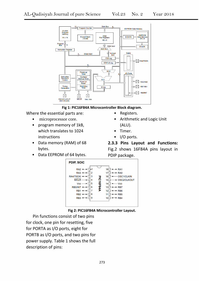
2.3.2: Block Diagram: A block
diagram of the device is shown in
Fig.1:
AL-Qadisiyah Journal of pure Science Vol.23 No. 2 Year 2018
273
Fig 1: PIC16F84A Microcontroller Block diagram.
Where the essential parts are:
• microprocessor core.
• program memory of 1kB,
which translates to 1024
instructions
• Data memory (RAM) of 68
bytes.
• Data EEPROM of 64 bytes.
• Registers.
• Arithmetic and Logic Unit
(ALU).
• Timer.
• I/O ports.
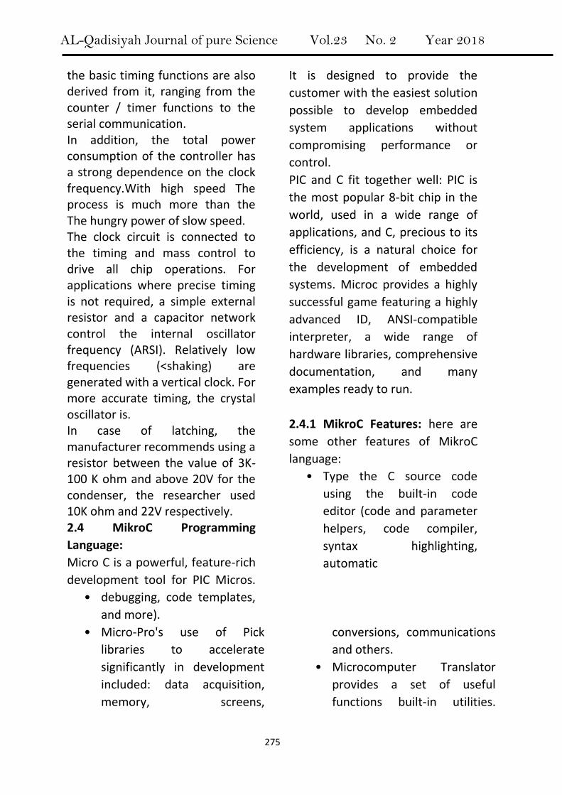
2.3.3 Pins Layout and Functions:
Fig.2 shows 16F84A pins layout in
PDIP package.
Fig 2: PIC16F84A Microcontroller Layout.
Pin functions consist of two pins
for clock, one pin for resetting, five
for PORTA as I/O ports, eight for
PORTB as I/O ports, and two pins for
power supply. Table 1 shows the full
description of pins:

AL-Qadisiyah Journal of pure Science Vol.23 No. 2 Year 2018
274
Pin Name PDIP No. I/O/P Type Description
OSC1/CLKIN 16 I Oscillator.
OSC2/CLKOUT 15 O Oscillator.
MCLR 4 I/O Master Clear (Reset) input/programming voltage Input. This pin is an active low RESET to the device.
RA0 RA1 RA2 RA3
RA4/T0CKI
17 18 1 2 3
I/O I/O I/O I/O I/O
PORTA is a bi-directional I/O port.
RB0/INT RB1 RB2 RB3 RB4 RB5 RB6 RB7
6 7 8 9
10 11 12 13
I/O I/O I/O I/O I/O I/O I/O I/O
PORTB is a bi-directional I/O port.
Vss 5 P Ground reference .
VDD 14 P Positive supply for logic and I/O pins. I=Input O=Output I/O= Input/Output P=Power
TABLE 1: PIC16F84A PINOUT DESCRIPTION.
2.3.4 PORTA, PORTB and TRISA
Registers:
PORTA is a 5-bit wide, bi-directional
port. The corresponding data
direction register is TRISA. Setting a
TRISA bit (= 1) will make the
corresponding PORTA pin as input.
Clearing a TRISA bit (= 0) will make
the corresponding PORTA pin as
output.
PORTB is an 8-bit wide, bi-
directional port. Also, direction
controlled by TRISB register in the
same way of PORTA.
All port pins have TTL input levels
and full CMOS output drivers. S1:15
2.3.5 Clock Oscillator and Instruction Cycle: Microprocessor or microcontroller is a complex electronic circuit, consisting of serial and standard logic. At a great speed, it steps in turn through a series of complex states, each state dependent on the sequence of instructions that are executed. While the details of this process are not visible to us, it is still necessary to provide "clock signal, constantly operate constant frequency square wave wave.The total speed of the microcontroller process depends entirely on this frequency clock.It is not only the processing unit In most microcontrollers, many of
AL-Qadisiyah Journal of pure Science Vol.23 No. 2 Year 2018
275
the basic timing functions are also derived from it, ranging from the counter / timer functions to the serial communication. In addition, the total power consumption of the controller has a strong dependence on the clock frequency.With high speed The process is much more than the The hungry power of slow speed. The clock circuit is connected to the timing and mass control to drive all chip operations. For applications where precise timing is not required, a simple external resistor and a capacitor network control the internal oscillator frequency (ARSI). Relatively low frequencies (<shaking) are generated with a vertical clock. For more accurate timing, the crystal oscillator is. In case of latching, the manufacturer recommends using a resistor between the value of 3K-100 K ohm and above 20V for the condenser, the researcher used 10K ohm and 22V respectively. 2.4 MikroC Programming
Language:
Micro C is a powerful, feature-rich
development tool for PIC Micros.
It is designed to provide the
customer with the easiest solution
possible to develop embedded
system applications without
compromising performance or
control.
PIC and C fit together well: PIC is
the most popular 8-bit chip in the
world, used in a wide range of
applications, and C, precious to its
efficiency, is a natural choice for
the development of embedded
systems. Microc provides a highly
successful game featuring a highly
advanced ID, ANSI-compatible
interpreter, a wide range of
hardware libraries, comprehensive
documentation, and many
examples ready to run.
2.4.1 MikroC Features: here are
some other features of MikroC
language:
• Type the C source code
using the built-in code
editor (code and parameter
helpers, code compiler,
syntax highlighting,
automatic
• debugging, code templates,
and more).
• Micro-Pro's use of Pick
libraries to accelerate
significantly in development
included: data acquisition,
memory, screens,
conversions, communications
and others.
• Microcomputer Translator
provides a set of useful
functions built-in utilities.

AL-Qadisiyah Journal of pure Science Vol.23 No. 2 Year 2018
276
Embedded functionality does
not require any header files to
be included. You can use it in
any part of your project. S2:
141
• Monitor the program
structure, variables, and
functions in Code Explorer.
• Use the integrated microcode
(in-circuit debugger) real-time
debugging tool to monitor
program execution at the
hardware level.
• Check program flow and
debug executable logic with
integrated software emulator.
2.4.2 MikroC Instructions Used:
here are some details about
instruction and rules used by the
researcher in this project:
Binary Constants: All constants
starting with Ob (or OB) are taken to
be binary. In the absence of any
overriding suffixes, the data type of
a binary constant is derived from its
value, according to the rules
presented above. For example, Obi
1011 will be treated as short.
(Delay_ms)
(Goto) Statement:
Colon: Use colon (:) to indicate a
labeled statement. For example Start: x = 0;
Goto start
(PORTA), (PORTB): assign a value for
port related; the value could be in
HEX format or BINARY in the form: PORTA=0B00000000
(TRISA), (TRISB): to indicate the
state of I/O ports weather are input
or output, assigning (0) to a bit
indicates that it is in input state, and
(1) indicates that it is in output state
3. Research Methodology: 3.1 Equipments, Tools and means
used:
3.1.1 Hardware Tools and
Electronic Components: researcher
used:
• Microcontroller chip.
• Power regulator 7805 as 5 V
regulated power supply.
• Two resistors of 10K and 420
Ohm.
• 22pf ceramic capacitor.
• main power supply.
• Twelve of LEDs.
• Laptop Computer .
• TopWin universal EEPROM
Programmer.
3.1.2 Software:
• MikroC pro.
• ISIS-Proteus, Version 7
simulator.
• TopWin universal
programmer software.
• Windows 7 .
3.2. Circuit Diagram and Building
the Experiment:
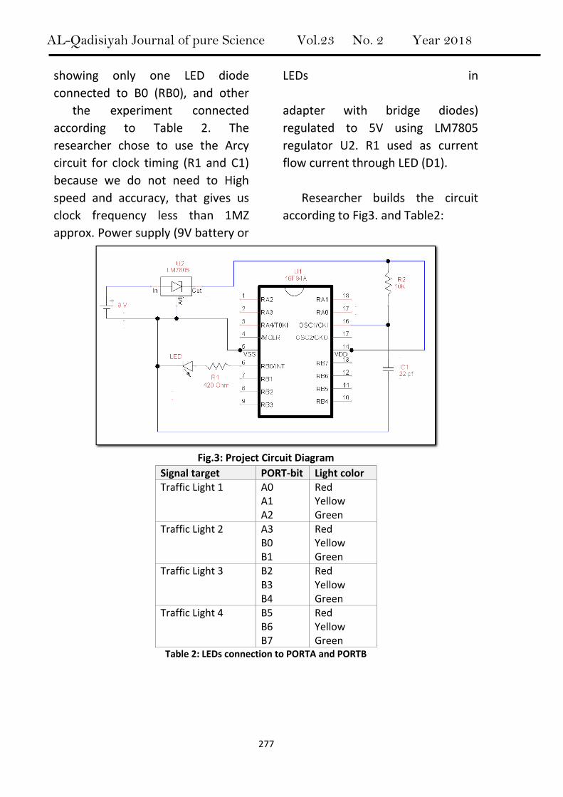
Figure 3 shows the typical
diagram of the circuit of the project,
AL-Qadisiyah Journal of pure Science Vol.23 No. 2 Year 2018
277
showing only one LED diode
connected to B0 (RB0), and other
LEDs in
the experiment connected
according to Table 2. The
researcher chose to use the Arcy
circuit for clock timing (R1 and C1)
because we do not need to High
speed and accuracy, that gives us
clock frequency less than 1MZ
approx. Power supply (9V battery or
adapter with bridge diodes)
regulated to 5V using LM7805
regulator U2. R1 used as current
flow current through LED (D1).
Researcher builds the circuit
according to Fig3. and Table2:
Fig.3: Project Circuit Diagram
Signal target PORT-bit Light color
Traffic Light 1 A0 A1 A2
Red Yellow Green
Traffic Light 2 A3 B0 B1
Red Yellow Green
Traffic Light 3 B2 B3 B4
Red Yellow Green
Traffic Light 4 B5 B6 B7
Red Yellow Green
Table 2: LEDs connection to PORTA and PORTB

AL-Qadisiyah Journal of pure Science Vol.23 No. 2 Year 2018
278
Overall electronic components required were: Item Type Value/No. Quantity
U1 IC 16F84A 1
U2 IC Lm 7805 1
R1 Resistor 10K Ohm 1
R2 Resistor 420 Ohm 1
C1 Capacitor 22 pf 1
D1-12 LED - 12
Table 3: Electronic Components.
3.3 Programming with mikroC
Language:
3.3.1 Designing and Coding the
Program: According to the
flowchart that we designed (see
supplement A, P: 13 for
flowchart detail), the researcher
used MikroC language for writing
code (see supplement B, P: 14
for code list). Instructions used
in the program of the project
limited by our needs only, which
are:
• TRISB and TRISB: for
setting the state of I/O
ports weather are input or
output.
• Delay_ms
• PORTA and PORTB
• Goto-Label
3.3.2 Debug and Compile the
Program: researchers found no
syntax error using built in mikroC
debugger. Then, the program
compiled successfully with no
errors.
3.3.3 Test the Program by
Simulation: we used SISI-Proteus
for
simulating our project as shown
in Fig.5, test passed successfully.
Fig.5 project Simulation using SISI-Proteus Software.
AL-Qadisiyah Journal of pure Science Vol.23 No. 2 Year 2018
279
3.3.4 Transfer the program to the
Microcontroller: researchers burned
the program to EEPROM of
Microcontroller using TopWin
universal programmer, the
operation done successfully without
errors.
3.3.5 Test overall the Project
practically:
After that, researcher operates
the project in reality; we found
that the project is working
properly as planned.
4. Results and discussion: According to both theoretical
and frameworks, the researcher
could built a basic device for
controlling traffic light successively,
this was just a basic project that
could be altered in number of lights,
tracks and timing according the
situation requirements.
5. Conclusions and
recommendations: 5.1 Conclusions:
According to the results, researcher
concludes the following:
• Building a control system
using PIC16F84A
Microcontroller is relatively
easy.
• Writing code for programming
PIC16F84A using MikroC
language is not complicated
process because of limit
instructions we need,
5.2 Recommendations:
The researcher recommends
the following:
• Developing the project by
adding power driver stage for
each output in order to
operate higher power bulbs to
use it in the real
• field.
• Adding more output lights,
e.g. for walkers, using more
advanced PIC microcontroller,
like PIC32MX microcontroller.
AL-Qadisiyah Journal of pure Science Vol.23 No. 2 Year 2018
280
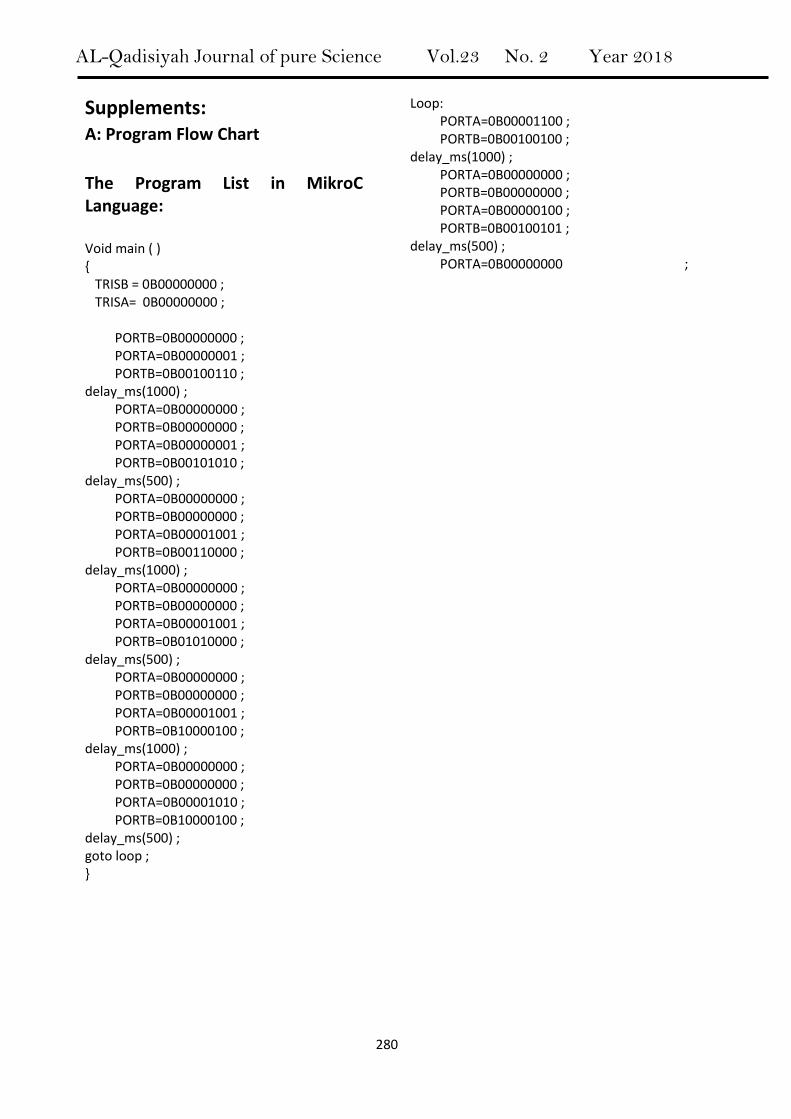
Supplements: A: Program Flow Chart
The Program List in MikroC Language: Void main ( ) { TRISB = 0B00000000 ; TRISA= 0B00000000 ;
Loop: PORTA=0B00001100 ; PORTB=0B00100100 ; delay_ms(1000) ; PORTA=0B00000000 ; PORTB=0B00000000 ; PORTA=0B00000100 ; PORTB=0B00100101 ; delay_ms(500) ; PORTA=0B00000000 ;
PORTB=0B00000000 ; PORTA=0B00000001 ; PORTB=0B00100110 ; delay_ms(1000) ; PORTA=0B00000000 ; PORTB=0B00000000 ; PORTA=0B00000001 ; PORTB=0B00101010 ; delay_ms(500) ; PORTA=0B00000000 ; PORTB=0B00000000 ; PORTA=0B00001001 ; PORTB=0B00110000 ; delay_ms(1000) ; PORTA=0B00000000 ; PORTB=0B00000000 ; PORTA=0B00001001 ; PORTB=0B01010000 ; delay_ms(500) ; PORTA=0B00000000 ; PORTB=0B00000000 ; PORTA=0B00001001 ; PORTB=0B10000100 ; delay_ms(1000) ; PORTA=0B00000000 ; PORTB=0B00000000 ; PORTA=0B00001010 ; PORTB=0B10000100 ; delay_ms(500) ; goto loop ; }