TRAFFIC CONTROL GUIDELINES - Harris County,...
33
HARRIS COUNTY PUBLIC INFRASTRUCTURE DEPARTMENT TRAFFIC CONTROL GUIDELINES November 2001
Transcript of TRAFFIC CONTROL GUIDELINES - Harris County,...

HARRIS COUNTY PUBLICINFRASTRUCTURE DEPARTMENT
TRAFFIC CONTROLGUIDELINES
November 2001
HARRIS COUNTY PUBLIC INFRASTRUCTURE DEPARTMENTTRAFFIC CONTROL GUIDELINES
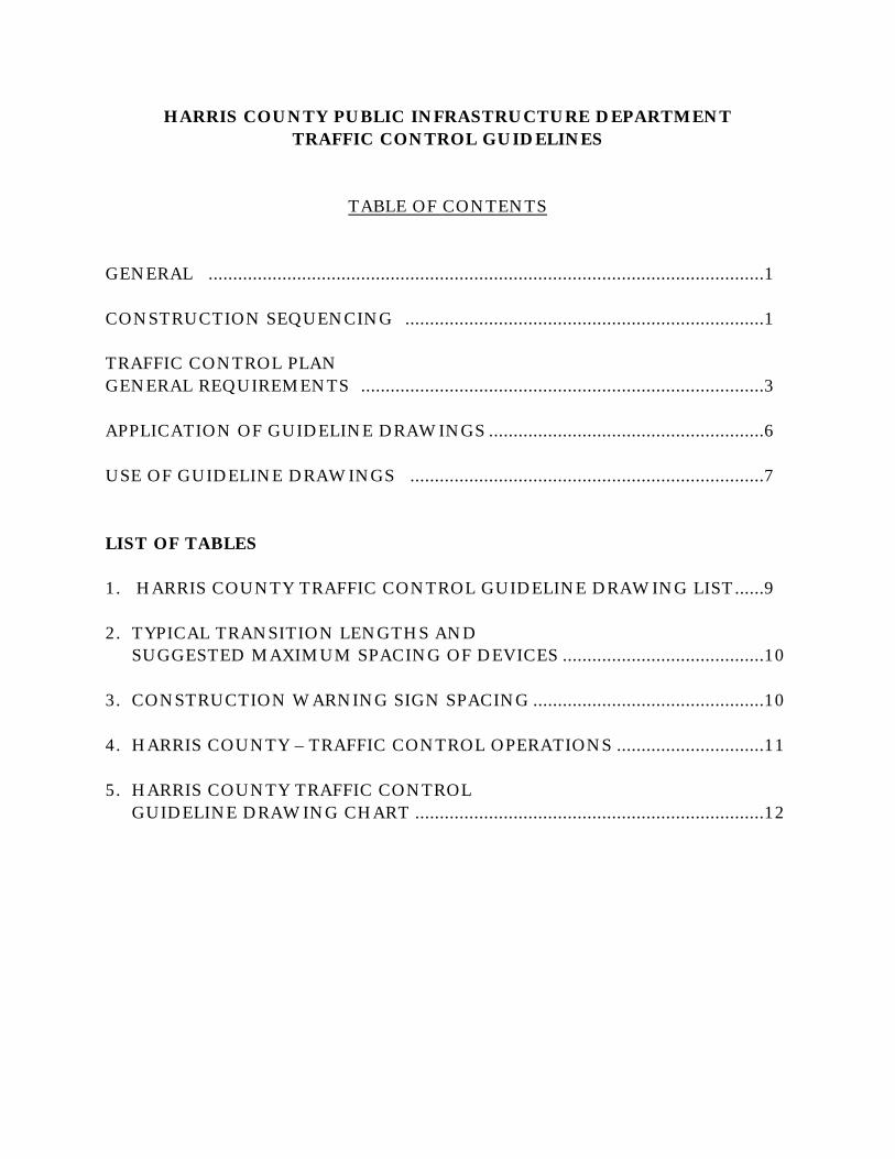
TABLE OF CONTENTS
GENERAL .................................................................................................................1
CONSTRUCTION SEQUENCING .........................................................................1
TRAFFIC CONTROL PLANGENERAL REQUIREMENTS ..................................................................................3
APPLICATION OF GUIDELINE DRAWINGS ........................................................6
USE OF GUIDELINE DRAWINGS ........................................................................7
LIST OF TABLES
1. HARRIS COUNTY TRAFFIC CONTROL GUIDELINE DRAWING LIST......9
2. TYPICAL TRANSITION LENGTHS ANDSUGGESTED MAXIMUM SPACING OF DEVICES .........................................10
3. CONSTRUCTION WARNING SIGN SPACING ...............................................10
4. HARRIS COUNTY – TRAFFIC CONTROL OPERATIONS ..............................11
5. HARRIS COUNTY TRAFFIC CONTROLGUIDELINE DRAWING CHART .......................................................................12
1
GENERAL
The Harris County Public Infrastructure Department has developed “Traffic ControlGuidelines” for use by Engineers in designing a Traffic Control Plan (TCP) for allconstruction activities within Harris County right-of-way. As part of the “TrafficControl Guidelines”, a set of guideline drawings will be provided to the Engineer fortheir use in designing a “Traffic Control Plan” for each project that Harris Countyundertakes. The Engineer who is to use these guideline drawings shall familiarizehimself with them, their proper usage and what is expected in the Traffic ControlPlan.
Construction Sequencing and Traffic Control Plan shall be in accordance with generaltraffic engineering principles and practices governing traffic control duringconstruction as prescribed by the guidelines of the “Texas Manual on Uniform TrafficControl Devices” (Texas MUTCD), and Harris County requirements.
Upon completion of the detailed Traffic Control Plan described herein, technicalspecifications and a detailed TCP cost estimate shall be completed. Quantities andcost estimates for each traffic control bid item shall be provided by the Engineer andapproved by Harris County.
CONSTRUCTION SEQUENCING
Construction Sequencing is a critical part of the Traffic control Plan. The conceptualsequencing of any project will be addressed in the preliminary engineering report. Toaccomplish this, information must be obtained that delineates the existingtopographic features, potential conflicts such as underground utilities and access toadjacent properties. This information combined with the proposed design elementsof the project may then be prioritized to establish a construction sequencing plan.
The construction of the project should be scheduled or sequenced to minimize thedown time for the contractor and to maximize the utilization of space for thetravelways. This Sequencing is accomplished by partitioning the project intoconstruction phases. The construction phases may be further fractionated into steps.The description of the phase and step components of a construction sequencing planis as follows.
A “phase” is a major portion of the construction, scheduled in a logicalprogression toward project completion. For example, a typical constructionphasing sequence might include the following: Phase I, construct temporarywidening to the east of the existing pavement and transfer traffic to it. Phase
2
II, construct the west half of the proposed roadway. Phase III, relocate trafficto new pavement and construct the east half of the proposed roadway.
A “step” is a minor portion of the construction, subordinate to a particularphase. For example, Phase II, Step I – Construct west roadway with drivewayleave-outs for local access; Phase II – Step II complete driveway leave-outsusing high early strength concrete.
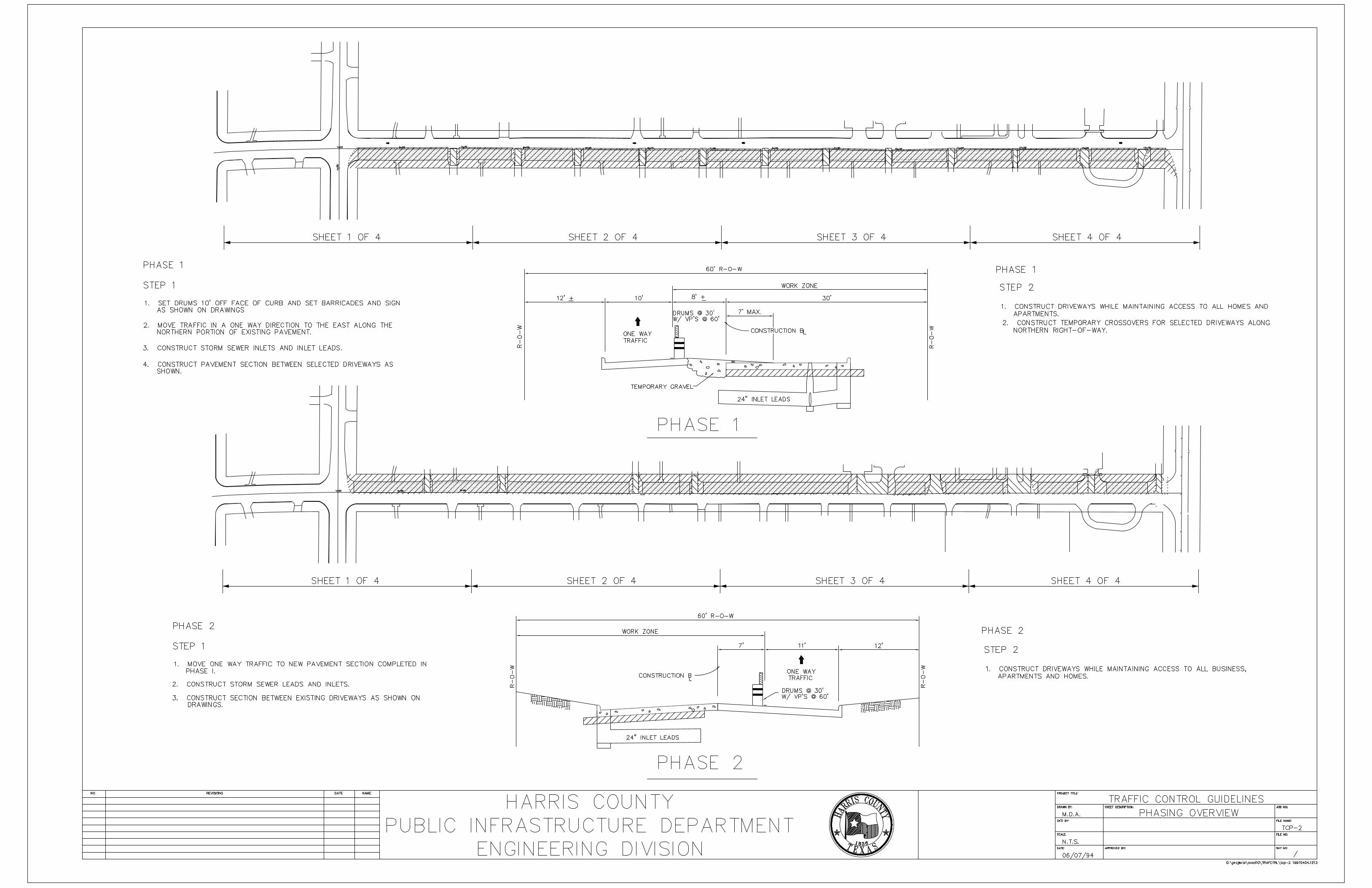
A sample phasing overview drawing (TCP-2) is provided in the TCP GuidelineDrawings.
The construction sequencing should be developed to confine the constructionactivities to a single lane at a time, whenever possible. Disruption of more than onelane of traffic, especially in the same direction, should be avoided. If, for any reason,construction has to take place in more than one lane at a time, consideration shouldbe given to scheduling the work during periods of low traffic volumes, such as duringweekends or off peak nighttime hours. Detouring traffic (routing the traffic off thenormal existing travel surface) if utilized as part of the TCP, must be investigated,documented and approved by Harris County Public Infrastructure Department,Traffic and Transportation Group.
The drawings of the construction sequence should have a plan view of the project.the plan view should clearly distinguish areas of construction with areas of traffic foreach phase. This may be accomplished by some form of shading, hatching orcoloring. The work zone is to be distinguished from the actual construction limits(i.e. actual paving being constructed). Likewise, when phasing consists of multiplesteps, the different steps should be clearly defined by contrasting patterns or coloring.
In conjunction with plan view sequencing of the project, typical sections should bedeveloped at representative locations along the project. These sections should show:the existing and proposed construction elements, traffic lanes, work zone,construction pavement markings, barriers and buffer zones, anticipated drop-off’sand/or key elevational differences in the construction of the project. The typicalsections should be drawn to an appropriate scale and be clearly dimensioned andannotated. These sections should be included with the plan view constructionsequencing in the preliminary engineering report for approval by Harris CountyPublic Infrastructure Department, Traffic and Transportation Group.
In developing the representative sections, a minimum travel lane width of ten (10)feet shall be maintained. If space is not available within the existing facility,temporary widening of the pavement section may be necessary to provide a minimumten (10) foot travel lane. The sections should coincide with the plan view in terms ofclearly defining areas of traffic, the work zone and the construction limits bymatching the shading or hatching of the plan view.
3
The Engineer shall meet with Harris County Public Infrastructure Department,Traffic and Transportation Group during the following three (3) stages of the designprocess, as a minimum:
1. Prior to submittal of the preliminary engineering report to determine thecritical objectives of the plan: whether sequencing can be accomplished withminimal lane closings, what level-of-service is adequate, etc.
2. Upon completion of preliminary engineering report and prior to start ofdetailed design, the Construction Sequencing Plan comments should bediscussed and refined prior to proceeding with detailed design of the TrafficControl Plan.
3. Upon completion of a detailed Traffic Control Plan to review the drawings,specifications and quantity estimates for completeness.
TRAFFIC CONTROL PLAN – GENERAL REQUIREMENTS
Once the Construction Sequencing is established and approved by Harris County, theTraffic Control Plan (TCP) can be designed. The primary purpose of the TCP is toprotect the traveling public and provide a safe area for construction. The TCP shouldfollow expeditious steps toward completion of the project within the federal, stateand Harris County standards and guidelines. To accomplish this, TCP drawingsshould provide sufficient details, complete with all necessary placement of barricades,signing, pavement markings, delineation, detours, temporary traffic signals and theiradjustments and any other devices necessary to safely control traffic through theconstruction zones.
Wherever possible, the Traffic Control Plan should utilize the current phaseplacement of control devices to implement the next phase. By proper coordination ofthe construction sequencing, the traffic control plans can be simplified by utilizingportions of the current arrangement and devices already in place, for the next phase.
The Traffic Control Plan should contain the following four (4) basic elements:
1. Project approach signing.2. Phasing overview.3. Detailed plans for each phase of construction (including steps if any).4. Necessary TCP details (this includes all applicable Harris County TCP
Details).
4
1. Project approach signing.
The project approach signing drawings may be completed in linear fashion(stick drawing) or to an appropriate scale and will indicate the overall projectlimits and all necessary approach signing to be set up prior to the beginning ofconstruction. All signing will be properly annotated and dimensioned.Engineering notes, which apply to the overall Traffic Control Plan, may also beplaced on this sheet.
2. Phasing overview.
The phasing overview drawing, depending upon the complexity of the TCP, isintended to convey the overall phasing of the project on a single drawing. Ifthe project is complex and/or the phasing cannot be shown clearly on a singledrawing, multiple drawings (one (1) phase per drawing) should be utilized.This drawing should also contain a brief description, on a step by step basis, asto the construction activities anticipated, and in what order, for the shownphase and where typical sections are cut. If sufficient space is available, typicalsections may be included on this drawing for completeness.
3. Detailed plans for each phase of construction (including steps if any).
Following each phasing overview drawing is the set of detailed traffic controlplans needed for each phase. The detailed plan has itself a set of requirementsindicating completeness, which must be met by the Engineer.
• Travel lane widths shall not be less than 10 feet.
• The TCP’s should be designed to maintain the existing posted speedduring the construction. If speed reductions are necessary, everyattempt should be made to limit the reduction to no greater than 10mph below the existing posted speed. If reductions beyond this areunavoidable, these speed reductions should be done in incremental stepswith Harris County Public Infrastructure Department, TrafficEngineering Section approval.
• The TCP’s must emphasize maintaining the existing number of travellanes during implementation, except for construction phase changes andthen only during prescribed hours of low traffic as determined from acurrent traffic analysis.
• TCP’s should be prepared at a scale not smaller than 1”=50’ for full sizedrawings (24” x 36”) or 1”=100’ for half size (11” x 17”) drawings.

5
• Typical cross sections showing the existing and proposed constructioncomplete with traffic lanes, construction pavement markings,delineators, barriers, buffer zones by barrels or CTB’s, pavement drop-offs and construction details as applicable, shall be shown for allrepresentative situations adjacent to their location in the plan view. Thetypical sections should be drawn to an appropriate scale and be clearlydimensioned and annotated.
• All construction signing shall be represented pictorially and designatedwith the appropriate identification numbers as shown in the TexasMUTCD.
• All other traffic control devices shall be shown pictorially and properlylabeled on both the plan and cross section views.
• TCP’s shall be complete, noting all barricades, signing, pavementmarkings, delineation, detours, etc., necessary to control traffic duringthe construction process.
4. Necessary TCP details (this includes all Harris County Barricade &Construction Details).
Following the detail TCP drawings, sufficient details at an appropriate scaleshould be provided for the implementation of these plans for uniquesituations. These details may consist of but not be limited to: specific traffichandling at major intersections, traffic signal movements, handling of publicand private driveways, special utility construction, detour layouts andpavement sections, etc. Inclusion of Harris County’s barricades andconstruction devices as appropriate.
Speed Limits on Construction Projects:
The Engineer should determine and recommend a construction zone design speed forthe project. Advisory speed signs (orange and black) are mainly suggested for use onprojects with spot or short speed reduction needs and projects where the advisoryspeed is no more than 10 mph below the posted speed or the observed 85th percentilespeed. Speed limits for the entire length of a longer project where the advisory speedis more than 10 mph below the posted speed limit or the observed 85th percentilespeed can be established below the posted speed utilizing regulatory (black andwhite) speed zone signs. The recommended speed should be reasonable and safe forthe traveling public under the conditions found. Any such recommendation shouldbe documented in the traffic engineering study and approved by Harris CountyPublic Infrastructure Department, Traffic and Transportation Group.

6
Advisory Speed Plate:
If the construction zone design speed is lower than the existing posted speed, themaximum recommended speed through the construction area may be indicated byorange and black advisory speed limit plate (for use with orange construction andmaintenance signs, as per the T.M.U.T.C.D.). Please note that advisory speeds are“recommended” speeds for the benefit and assistance of the vehicle operator, notmandated and enforced by law.
Regulatory Speed Zones:
Reduction of the existing posted regulatory speed limit (or alteration of the primafacie speed limits) using black and white regulatory signs, must be made based on acomprehensive engineering or traffic investigation, and authorized by the CountyCommissioners Court or the governing body of an incorporated city, town or villagein which the project resides. If it is found to be necessary to alter the existing speedlimit, and it has been studied and authorized, the new speed limit is enforceable. Allexisting regulatory speed limit signs must then be covered or removed and replacedwith the temporary construction zone regulatory speed signs.
APPLICATIONS OF GUIDELINE DRAWINGS
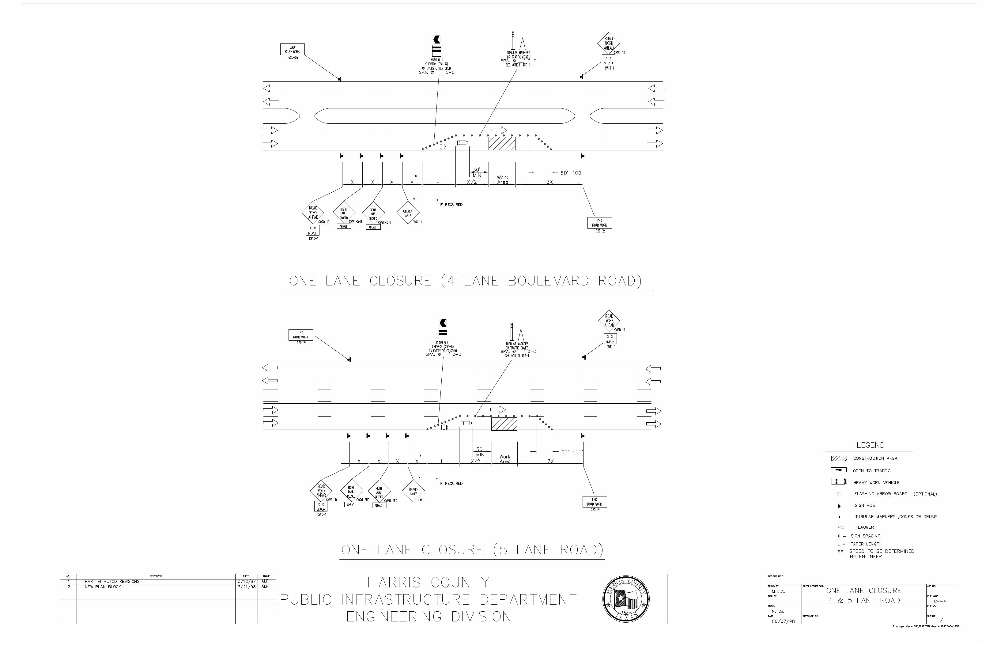
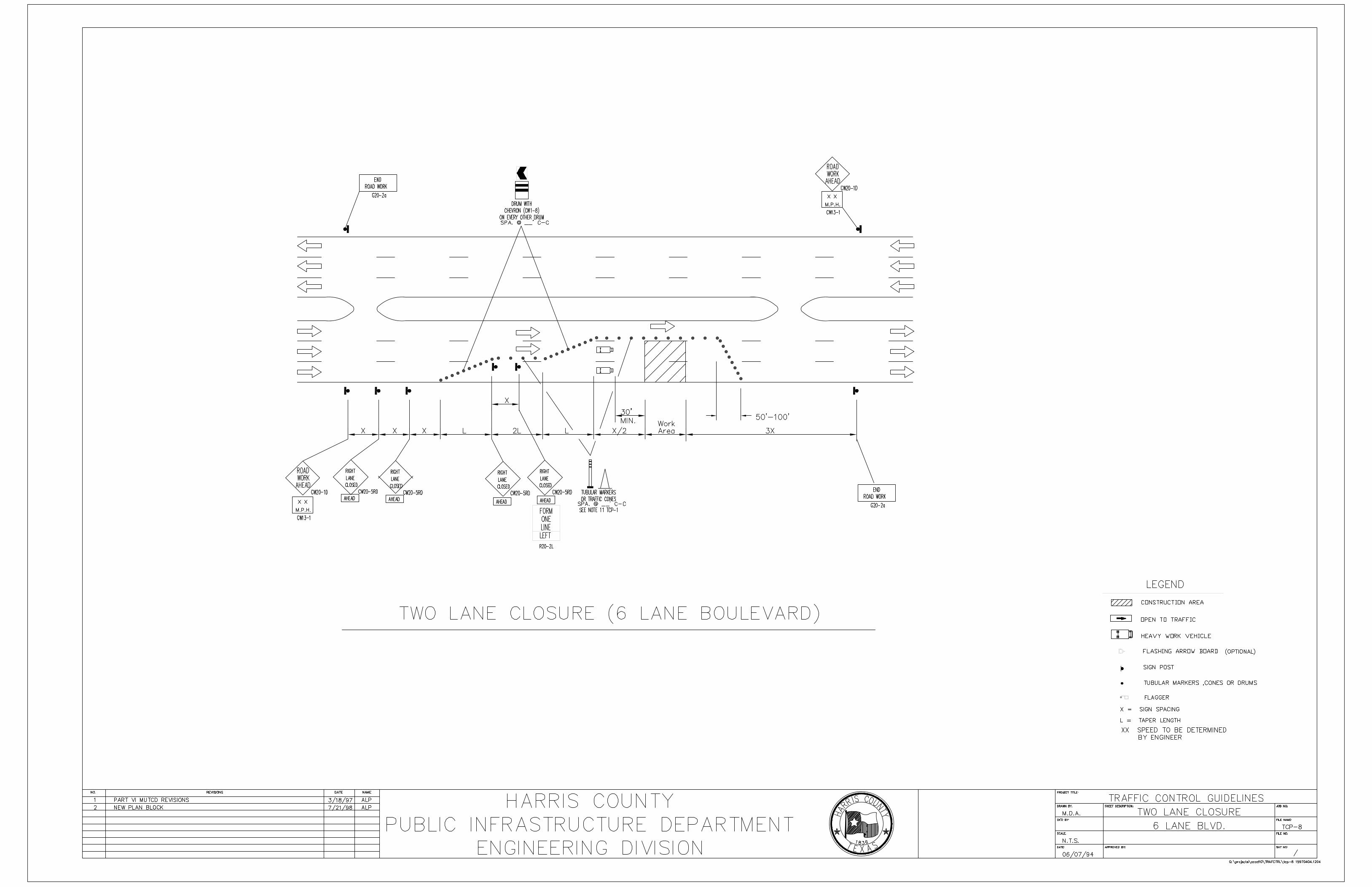
A set of guideline drawings has been prepared to assist the Engineer in designing aTraffic Control Plan for a given project. The guideline drawings represent anarrangement of traffic control devices for a given situation. These guideline drawingsshow a deployment of a number of devices that represent a minimum requirement.Therefore, if in the judgement of the Engineer, additional signing is needed for aparticular situation, it is advisable to add whatever is in the best interest of the safetyof the public and the project.
In general, these guideline drawings should be used as a template or an example ofhow, where and how many devices to deploy in any particular situation.
After review of the typical construction and maintenance projects undertaken byHarris County, a set of guideline drawings have been developed (see Table No. 1) toaddress the typically encountered construction activities. These activities are broadenough to cover several kinds of construction operations. Therefore, in order toapply any one of the guideline drawings, the Engineer must have defined his particularconstruction operations in terms of the items of construction, space requirements andtime of completion. These considerations apply to whether the entire project is beingconsidered or only one construction phase at a time.
7
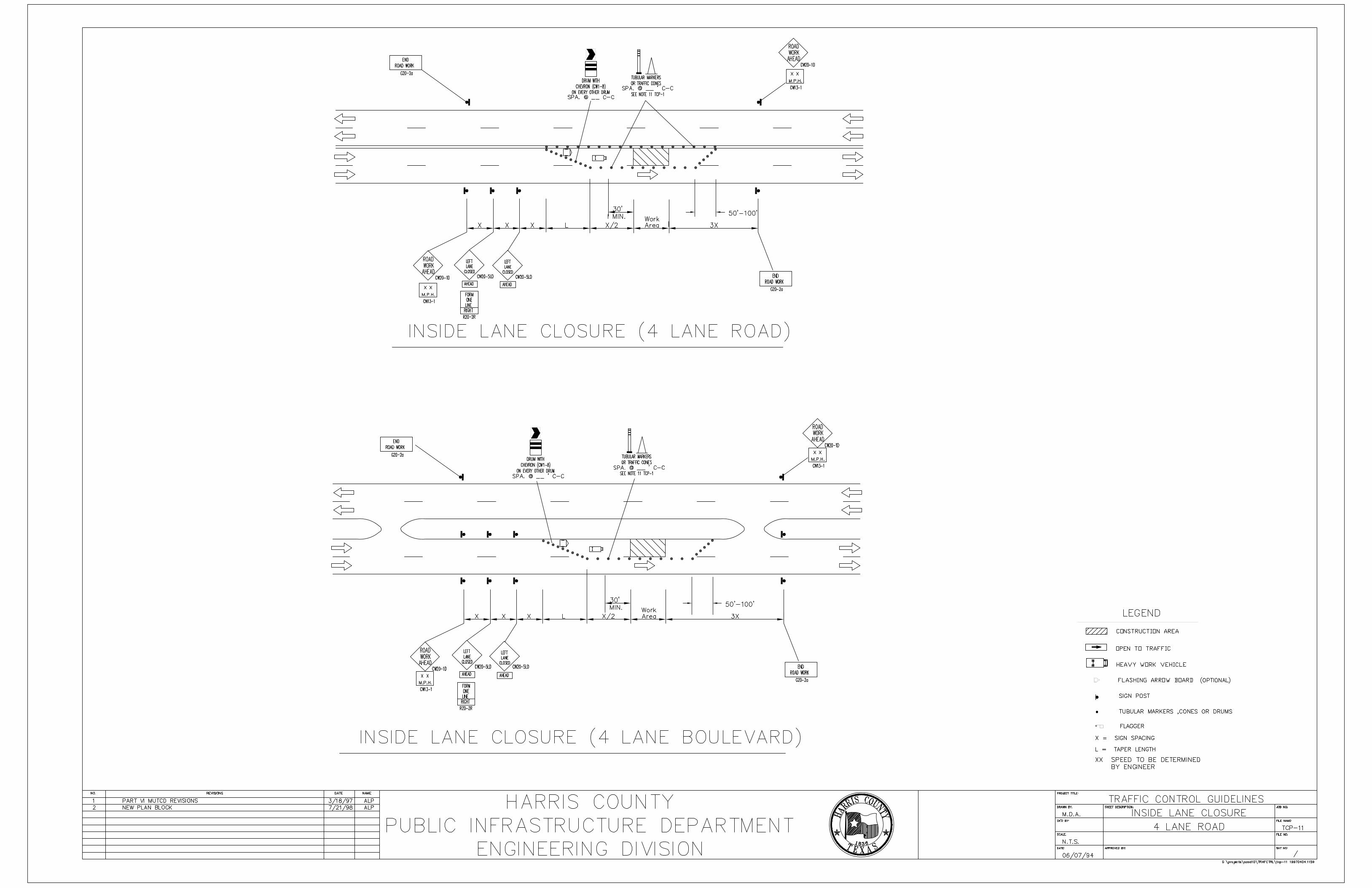
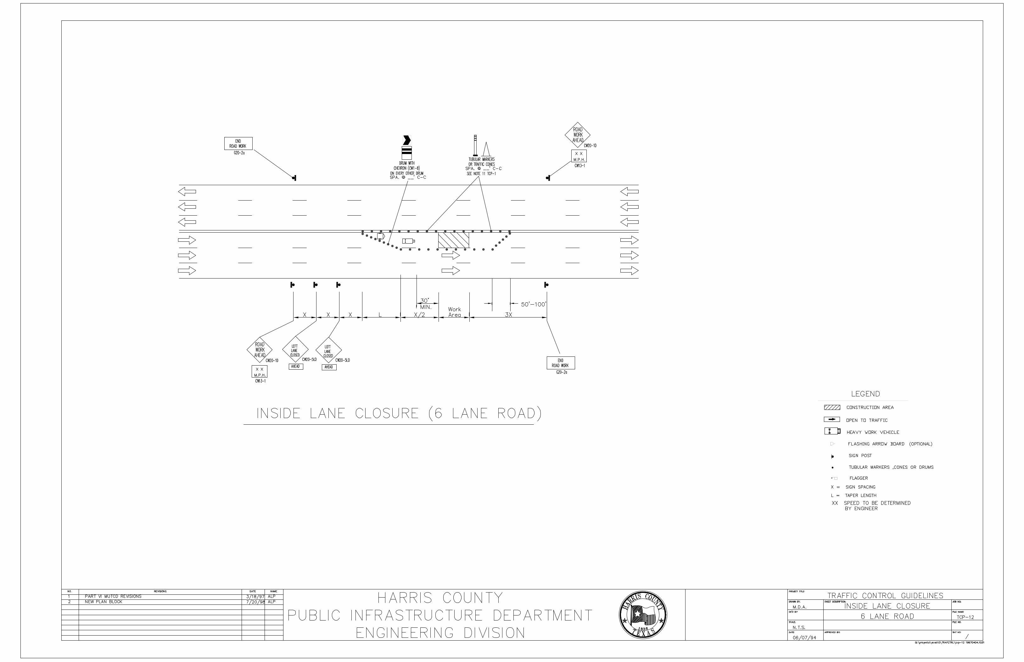
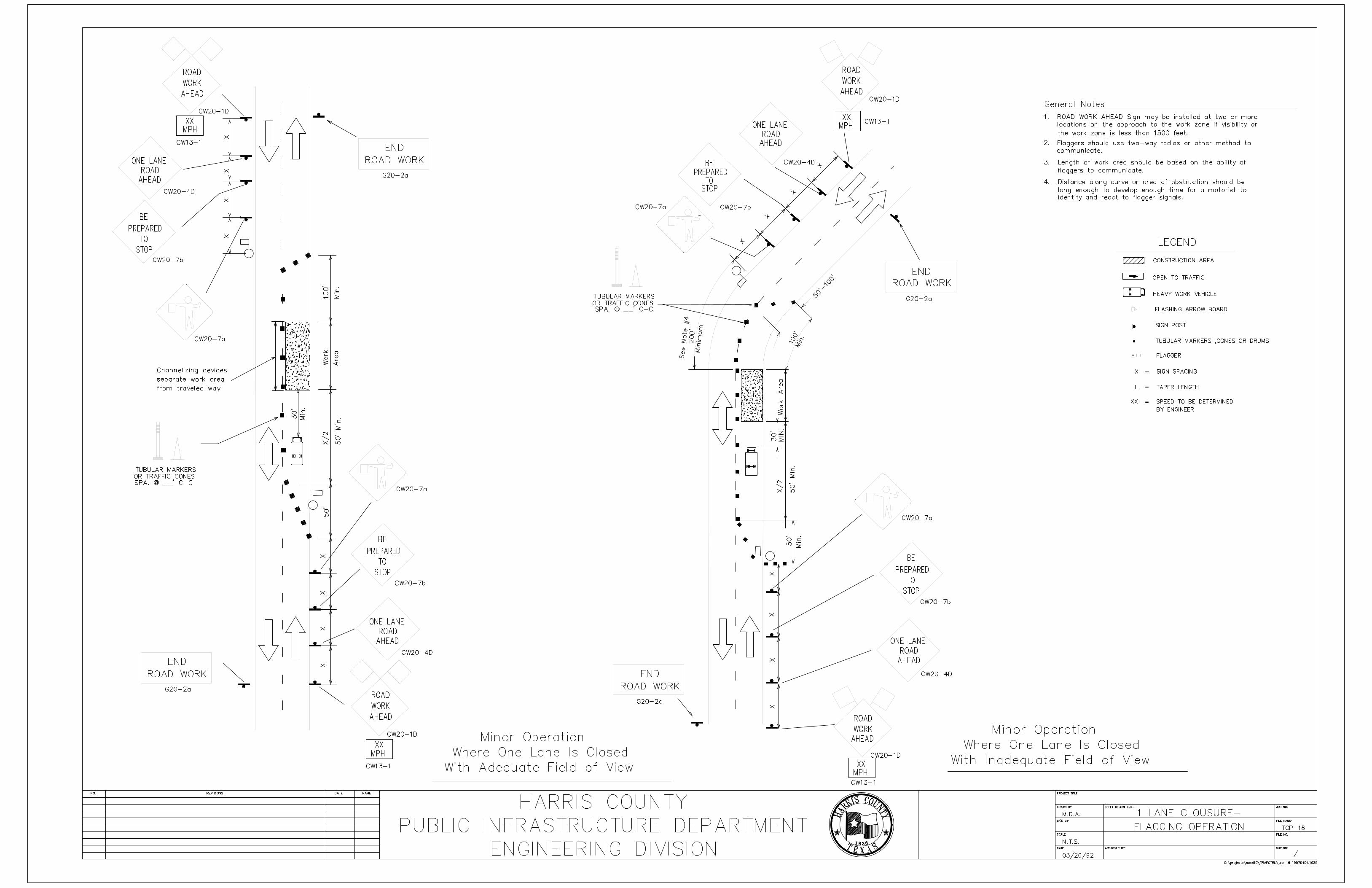
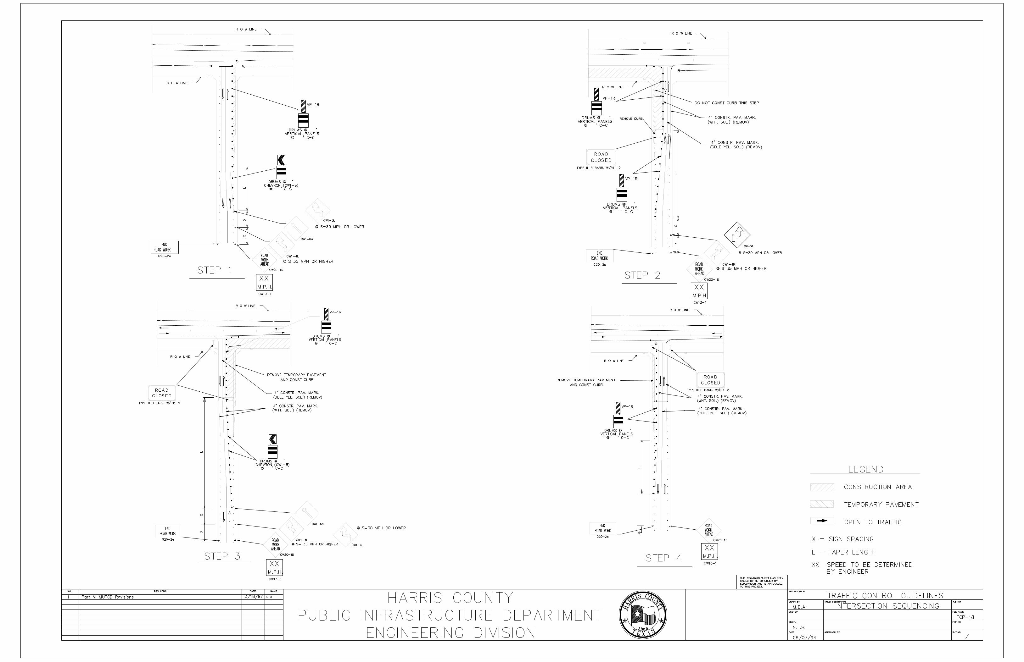
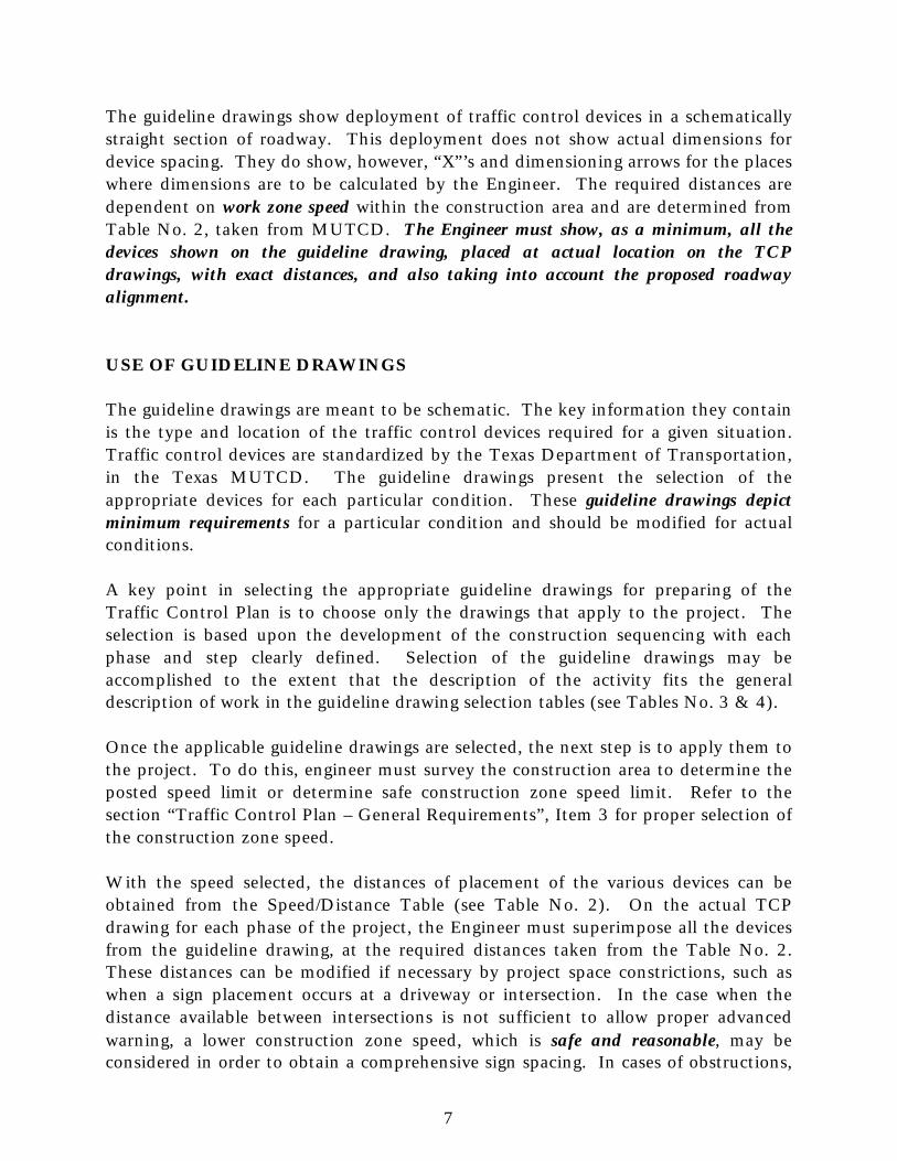
The guideline drawings show deployment of traffic control devices in a schematicallystraight section of roadway. This deployment does not show actual dimensions fordevice spacing. They do show, however, “X”’s and dimensioning arrows for the placeswhere dimensions are to be calculated by the Engineer. The required distances aredependent on work zone speed within the construction area and are determined fromTable No. 2, taken from MUTCD. The Engineer must show, as a minimum, all thedevices shown on the guideline drawing, placed at actual location on the TCPdrawings, with exact distances, and also taking into account the proposed roadwayalignment.
USE OF GUIDELINE DRAWINGS
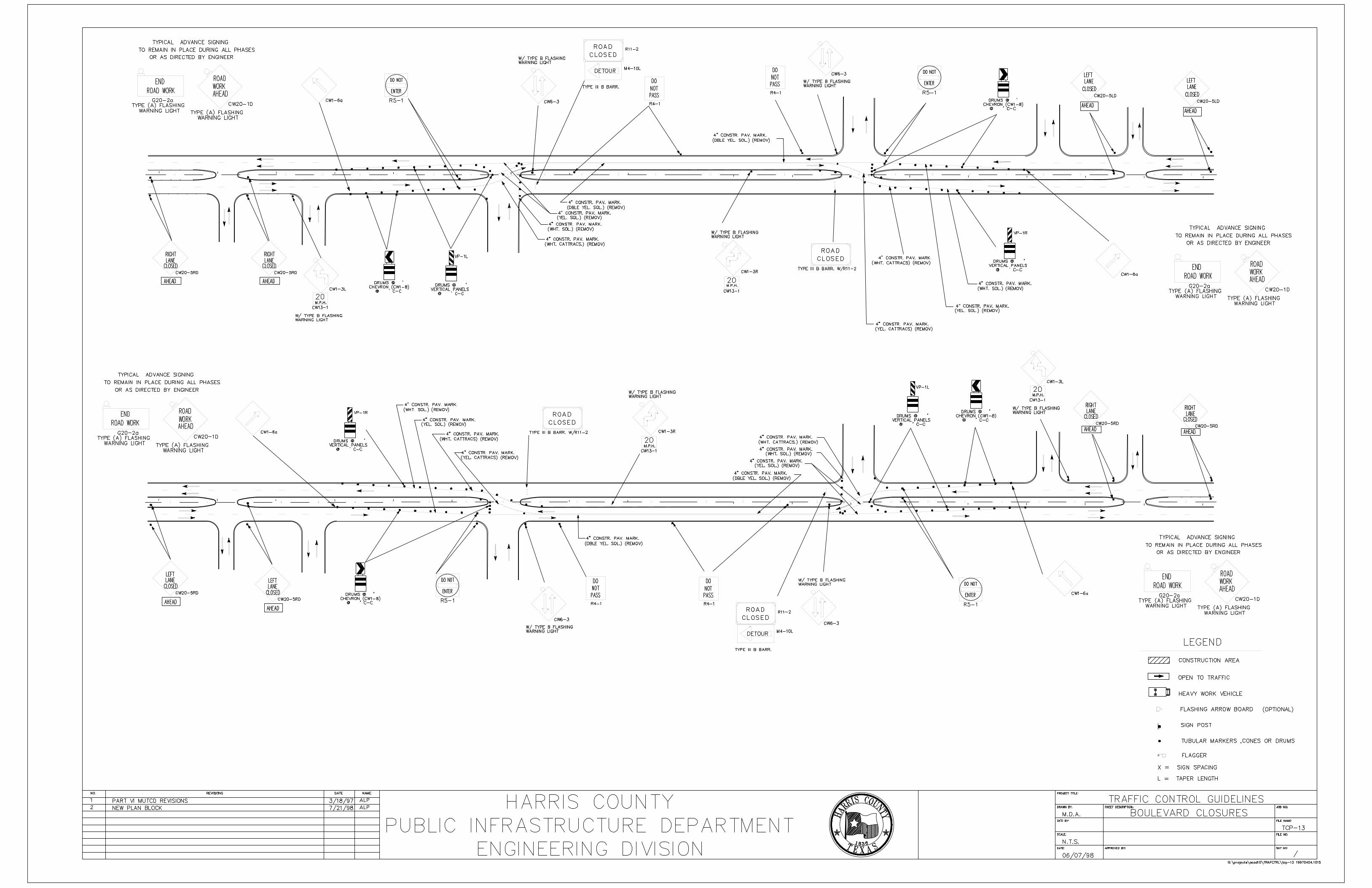
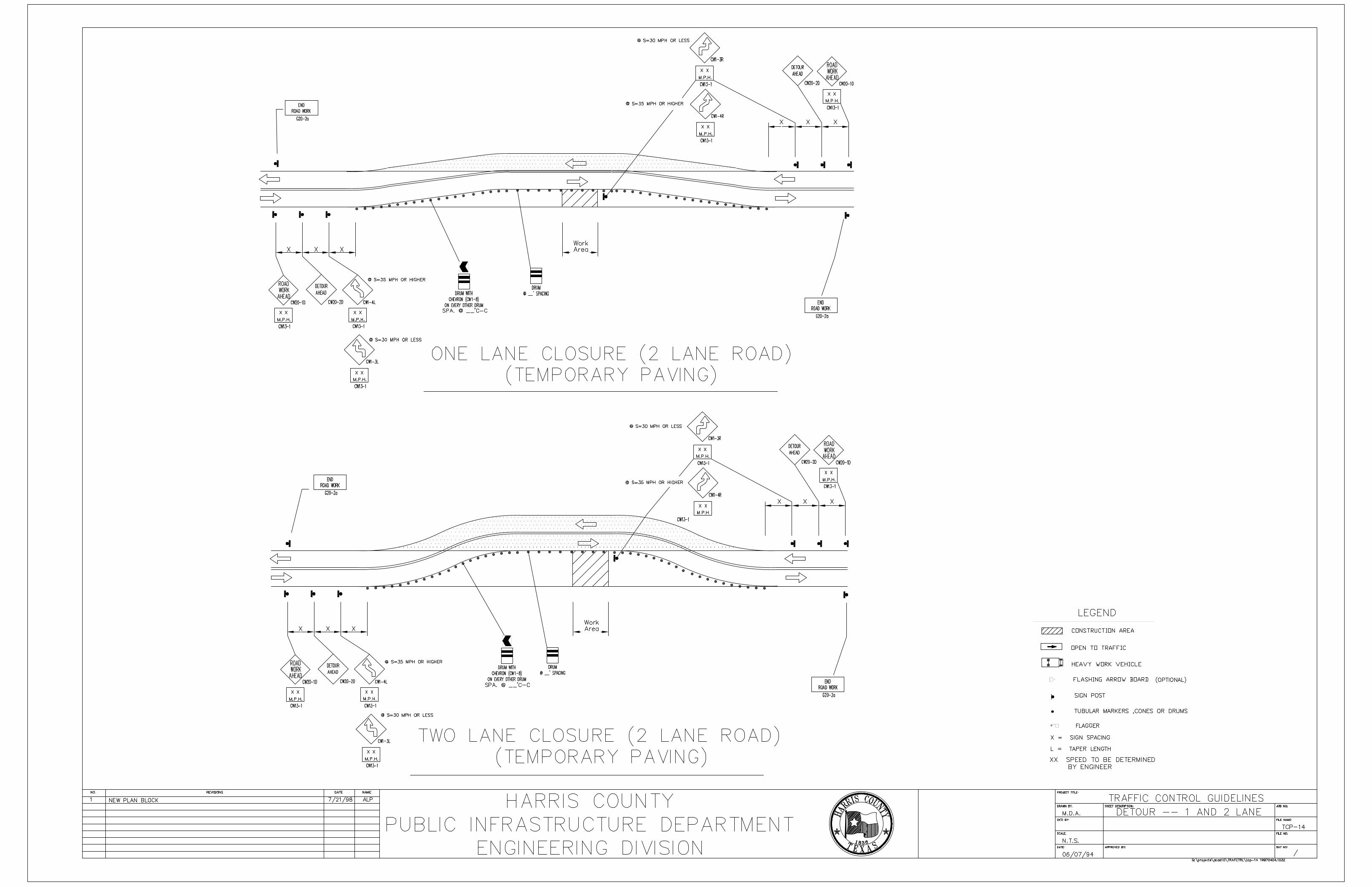
The guideline drawings are meant to be schematic. The key information they containis the type and location of the traffic control devices required for a given situation.Traffic control devices are standardized by the Texas Department of Transportation,in the Texas MUTCD. The guideline drawings present the selection of theappropriate devices for each particular condition. These guideline drawings depictminimum requirements for a particular condition and should be modified for actualconditions.
A key point in selecting the appropriate guideline drawings for preparing of theTraffic Control Plan is to choose only the drawings that apply to the project. Theselection is based upon the development of the construction sequencing with eachphase and step clearly defined. Selection of the guideline drawings may beaccomplished to the extent that the description of the activity fits the generaldescription of work in the guideline drawing selection tables (see Tables No. 3 & 4).
Once the applicable guideline drawings are selected, the next step is to apply them tothe project. To do this, engineer must survey the construction area to determine theposted speed limit or determine safe construction zone speed limit. Refer to thesection “Traffic Control Plan – General Requirements”, Item 3 for proper selection ofthe construction zone speed.
With the speed selected, the distances of placement of the various devices can beobtained from the Speed/Distance Table (see Table No. 2). On the actual TCPdrawing for each phase of the project, the Engineer must superimpose all the devicesfrom the guideline drawing, at the required distances taken from the Table No. 2.These distances can be modified if necessary by project space constrictions, such aswhen a sign placement occurs at a driveway or intersection. In the case when thedistance available between intersections is not sufficient to allow proper advancedwarning, a lower construction zone speed, which is safe and reasonable, may beconsidered in order to obtain a comprehensive sign spacing. In cases of obstructions,

8
the distance can be changed to clear the obstruction with the understanding thatdistances shown on Table No. 2 are minimum requirements.
In summary, to use the guideline set of traffic control drawings, the Engineer shouldcomplete the following drawing selection process steps:
1. Develop a comprehensive construction sequence plan for the project andobtain Harris County Public Infrastructure Department, Traffic andTransportation Group approval.
2. Create a phasing overview drawing showing each phase of construction andsteps of the major construction activities (Ref: Phasing Overview Dwg. TCP-2).
3. Create the project approach sign layout drawing for the current constructionproject (Ref: Project Approach Signing TCP-1).
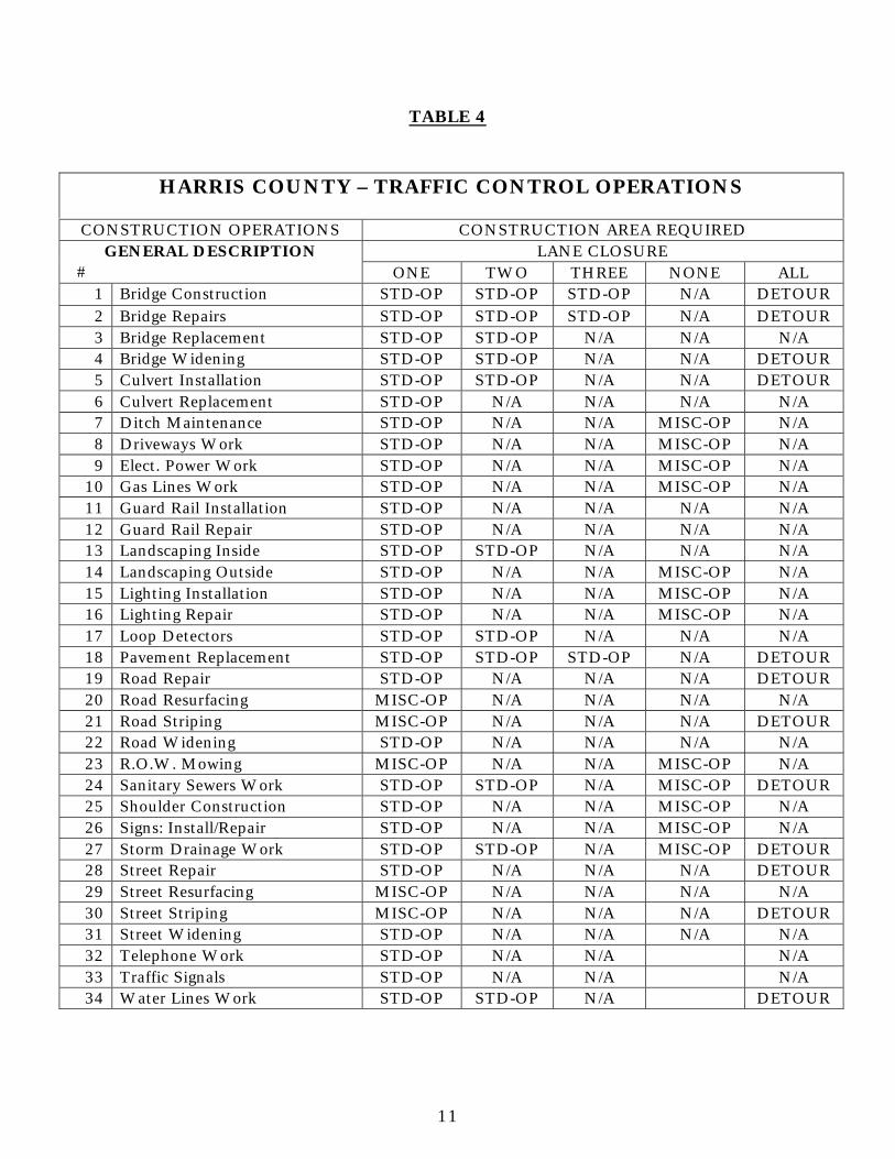
4. Locate in Table 4 (Harris County – Traffic Control Operations) under the“Construction Operations” column, the construction operation that bestdescribes the project. Locate, in Table 4, under the “Construction AreaRequired” column, the lane closure conditions required by the project’sconstruction operation.
5. With the information developed on the steps above, find the applicableguideline drawings. This is done by referring to Table 5 (Harris County TrafficControl Guideline Drawing Chart) and looking at the operation area required,i.e.: one lane closure, in relation to the roadway section, i.e.: 4 lane road, tofind the applicable guideline drawings. The list of guideline drawings can befound in Table 1 (Harris County Traffic Control Guideline Drawing List).
6. Conduct appropriate traffic study and determine the construction zone speed,preferably the existing posted speed, and calculate the appropriate devicespacing. This step is accomplished by following the directions in Tables 2 and3 (Speed/Device Spacing).
7. If the appropriate work zone design speed is determined to be �15 mph lessthan the posted speed limit, it may be necessary to temporarily change theposted speed limit and/or post additional signs to inform the public that trafficfines may be doubled in the work zone. Any changes to the posted speed limitmust be approved by HCPID and Harris County Commissioners’ Court.
8. Complete the TCP drawings and necessary details.
9. Prepare the required specifications and cost estimate.

9
TABLE NO. 1
HARRIS COUNTY TRAFFIC CONTROLGUIDELINE DRAWING LIST
DWG NO. DESCRIPTIONTCP-1 PROJECT APPROACH SIGNINGTCP-2 PHASING OVERVIEWTCP-3 ONE LANE CLOSURE-3 & 4 LANE ROADTCP-4 ONE LANE CLOSURE-4 & 5 LANE ROADTCP-5 ONE LANE CLOSURE-6 LANE ROADTCP-6 TWO LANE CLOSURE-4 LANE ROADTCP-7 TWO LANE CLOSURE-5 & 6 LANE ROADTCP-8 TWO LANE CLOSURE-6 LANE BLVD.TCP-9 SHOULDER WORKTCP-10 MEDIAN WORKTCP-11 INSIDE LANE CLOSURE-4 LANE ROADTCP-12 INSIDE LANE CLOSURE-6 LANE ROADTCP-13 BOULEVARD CLOSURESTCP-14 DETOURS-1 AND 2 LANETCP-15 TASK FORCE OPERATIONSTCP-16 1 LANE CLOSURE-FLAGGING OPERATIONTCP-17 FLAGGING/MOVING OPERATIONTCP-18 INTERSECTION SEQUENCINGTCP-19 CONSTRUCTION CROSSING EXISTING FACILITIES
10
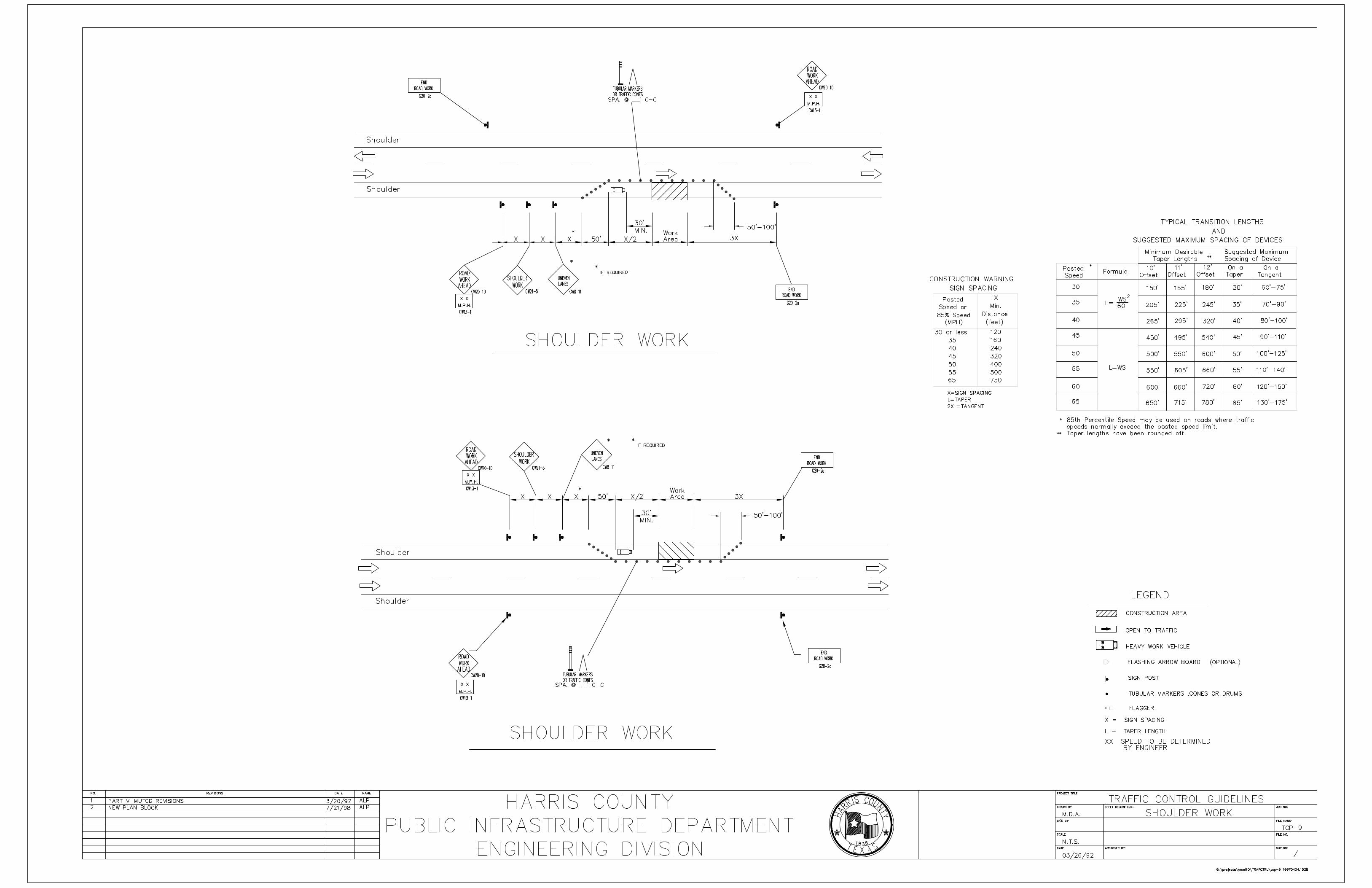
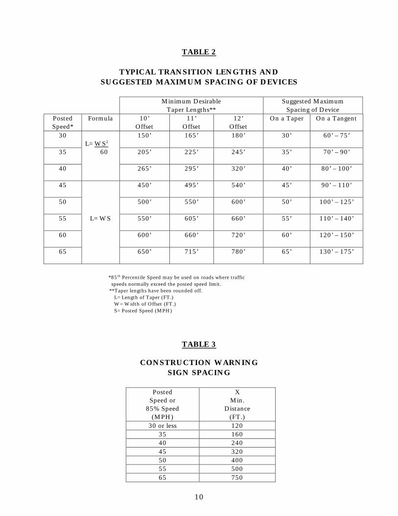
TABLE 2
TYPICAL TRANSITION LENGTHS ANDSUGGESTED MAXIMUM SPACING OF DEVICES
Minimum DesirableTaper Lengths**
Suggested MaximumSpacing of Device
PostedSpeed*
Formula 10’Offset
11’Offset
12’Offset
On a Taper On a Tangent
30 150’ 165’ 180’ 30’ 60’ – 75’
35 205’ 225’ 245’ 35’ 70’ – 90’
40
L=WS2
60
265’ 295’ 320’ 40’ 80’ – 100’
45 450’ 495’ 540’ 45’ 90’ – 110’
50 500’ 550’ 600’ 50’ 100’ – 125’
55 550’ 605’ 660’ 55’ 110’ – 140’
60 600’ 660’ 720’ 60’ 120’ – 150’
65
L=WS
650’ 715’ 780’ 65’ 130’ – 175’
*85th Percentile Speed may be used on roads where trafficspeeds normally exceed the posted speed limit.
**Taper lengths have been rounded off.L=Length of Taper (FT.)W=Width of Offset (FT.)S=Posted Speed (MPH)
TABLE 3
CONSTRUCTION WARNINGSIGN SPACING
PostedSpeed or
85% Speed(MPH)
XMin.
Distance(FT.)
30 or less 12035 16040 24045 32050 40055 50065 750
11
TABLE 4
HARRIS COUNTY – TRAFFIC CONTROL OPERATIONS
CONSTRUCTION OPERATIONS CONSTRUCTION AREA REQUIREDLANE CLOSUREGENERAL DESCRIPTION
# ONE TWO THREE NONE ALL1 Bridge Construction STD-OP STD-OP STD-OP N/A DETOUR2 Bridge Repairs STD-OP STD-OP STD-OP N/A DETOUR3 Bridge Replacement STD-OP STD-OP N/A N/A N/A4 Bridge Widening STD-OP STD-OP N/A N/A DETOUR5 Culvert Installation STD-OP STD-OP N/A N/A DETOUR6 Culvert Replacement STD-OP N/A N/A N/A N/A7 Ditch Maintenance STD-OP N/A N/A MISC-OP N/A8 Driveways Work STD-OP N/A N/A MISC-OP N/A9 Elect. Power Work STD-OP N/A N/A MISC-OP N/A
10 Gas Lines Work STD-OP N/A N/A MISC-OP N/A11 Guard Rail Installation STD-OP N/A N/A N/A N/A12 Guard Rail Repair STD-OP N/A N/A N/A N/A13 Landscaping Inside STD-OP STD-OP N/A N/A N/A14 Landscaping Outside STD-OP N/A N/A MISC-OP N/A15 Lighting Installation STD-OP N/A N/A MISC-OP N/A16 Lighting Repair STD-OP N/A N/A MISC-OP N/A17 Loop Detectors STD-OP STD-OP N/A N/A N/A18 Pavement Replacement STD-OP STD-OP STD-OP N/A DETOUR19 Road Repair STD-OP N/A N/A N/A DETOUR20 Road Resurfacing MISC-OP N/A N/A N/A N/A21 Road Striping MISC-OP N/A N/A N/A DETOUR22 Road Widening STD-OP N/A N/A N/A N/A23 R.O.W. Mowing MISC-OP N/A N/A MISC-OP N/A24 Sanitary Sewers Work STD-OP STD-OP N/A MISC-OP DETOUR25 Shoulder Construction STD-OP N/A N/A MISC-OP N/A26 Signs: Install/Repair STD-OP N/A N/A MISC-OP N/A27 Storm Drainage Work STD-OP STD-OP N/A MISC-OP DETOUR28 Street Repair STD-OP N/A N/A N/A DETOUR29 Street Resurfacing MISC-OP N/A N/A N/A N/A30 Street Striping MISC-OP N/A N/A N/A DETOUR31 Street Widening STD-OP N/A N/A N/A N/A32 Telephone Work STD-OP N/A N/A N/A33 Traffic Signals STD-OP N/A N/A N/A34 Water Lines Work STD-OP STD-OP N/A DETOUR
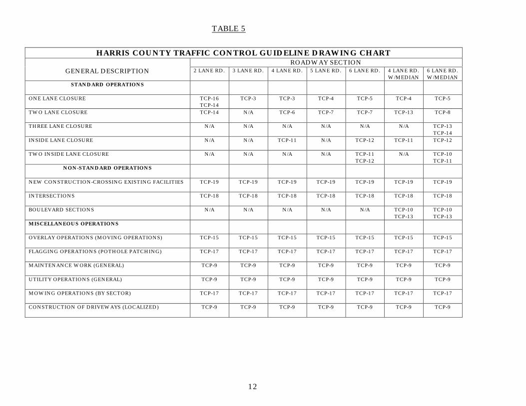
TABLE 5
12
HARRIS COUNTY TRAFFIC CONTROL GUIDELINE DRAWING CHARTROADWAY SECTION
GENERAL DESCRIPTION 2 LANE RD. 3 LANE RD. 4 LANE RD. 5 LANE RD. 6 LANE RD. 4 LANE RD.W/MEDIAN
6 LANE RD.W/MEDIAN
STANDARD OPERATIONS
ONE LANE CLOSURE TCP-16TCP-14
TCP-3 TCP-3 TCP-4 TCP-5 TCP-4 TCP-5
TWO LANE CLOSURE TCP-14 N/A TCP-6 TCP-7 TCP-7 TCP-13 TCP-8
THREE LANE CLOSURE N/A N/A N/A N/A N/A N/A TCP-13TCP-14
INSIDE LANE CLOSURE N/A N/A TCP-11 N/A TCP-12 TCP-11 TCP-12
TWO INSIDE LANE CLOSURE N/A N/A N/A N/A TCP-11TCP-12
N/A TCP-10TCP-11
NON-STANDARD OPERATIONS
NEW CONSTRUCTION-CROSSING EXISTING FACILITIES TCP-19 TCP-19 TCP-19 TCP-19 TCP-19 TCP-19 TCP-19
INTERSECTIONS TCP-18 TCP-18 TCP-18 TCP-18 TCP-18 TCP-18 TCP-18
BOULEVARD SECTIONS N/A N/A N/A N/A N/A TCP-10TCP-13
TCP-10TCP-13
MISCELLANEOUS OPERATIONS
OVERLAY OPERATIONS (MOVING OPERATIONS) TCP-15 TCP-15 TCP-15 TCP-15 TCP-15 TCP-15 TCP-15
FLAGGING OPERATIONS (POTHOLE PATCHING) TCP-17 TCP-17 TCP-17 TCP-17 TCP-17 TCP-17 TCP-17
MAINTENANCE WORK (GENERAL) TCP-9 TCP-9 TCP-9 TCP-9 TCP-9 TCP-9 TCP-9
UTILITY OPERATIONS (GENERAL) TCP-9 TCP-9 TCP-9 TCP-9 TCP-9 TCP-9 TCP-9
MOWING OPERATIONS (BY SECTOR) TCP-17 TCP-17 TCP-17 TCP-17 TCP-17 TCP-17 TCP-17
CONSTRUCTION OF DRIVEWAYS (LOCALIZED) TCP-9 TCP-9 TCP-9 TCP-9 TCP-9 TCP-9 TCP-9