Traffic Control Equipment Interfacing Specification · MOVA units 2.9.1 A 5 amp fused supply shall...
29
traffic systems and signing © Crown Copyright 2005 First published 2005 Printed and published by the Highways Agency TR 2523 Issue A Sept 2005 Traffic Control Equipment Interfacing Specification
Transcript of Traffic Control Equipment Interfacing Specification · MOVA units 2.9.1 A 5 amp fused supply shall...

traffic systems and signing
© Crown Copyright 2005
First published 2005
Printed and published by the Highways Agency
TR 2523 Issue A
Sept 2005
Traffic Control Equipment Interfacing
Specification

TR 2523 A Traffic Control Equipment Interfacing Specification
ii
(This page left intentionally blank)

TR 2523 A Traffic Control Equipment Interfacing Specification
iii
TR 2523 A TRAFFIC CONTROL EQUIPMENT INTERFACING SPECIFICATION
CONTENTS Section
1 Introduction
2 Controller Equipment Interfaces and Power Supplies
3 Ancillary Equipment Interfaces and Power Supply Requirements
4 Urban Traffic Control (UTC)
5 Normative References
6 History
Appendix A Cable Details
TR 2523 A Traffic Control Equipment Interfacing Specification
iv
(This page left intentionally blank)

TR 2523 A Traffic Control Equipment Interfacing Specification
1
1 INTRODUCTION 1.1 This technical requirement
specification covers the United Kingdom’s established interface standards for traffic control and ancillary equipment.
1.2 This document describes the interfaces that should be considered by Design Authorities of new products, who wish to offer these as possible replacements for existing approved products within the United Kingdom or for new schemes intended to combine approved traffic control equipment from other suppliers.
Glossary of Terms
1.3 A comprehensive glossary of terms is given in Highways Agency document TA 84 Code of Practice for Traffic Control and Information Systems for All-purpose Roads.

TR 2523 A Traffic Control Equipment Interfacing Specification
2
2 CONTROLLER EQUIPMENT INTERFACES AND POWER SUPPLIES
Communication Interfaces
2.1 Serial Interface
2.1.1 The serial interface, as commonly used for connection of the User’s Terminal, shall conform with the RS 232C, CCITT V24 and V28 definition, and operates using a separately protected +5V ± 5% power supply, with a minimum current rating of 250 mA.
2.1.2 The method of connection shall be a Cannon DP 25s or equivalent and shall have the following pin allocations:
Pin 1 Protective Ground
Pin 2 Transmitted Data from terminal to controller
Pin 3 Received Data from controller by terminal
Pin 4 Request from terminal to Send
Pin 5 Clear to Send from controller
Pin 6 Data Set Ready from controller
Pin 7 Signal Ground
Pin 9 + 5 V supply *
Pin 10 + 5 V supply *
Pin 18 Ground (0 V supply)
Pin 19 Ground (0 V Supply)
Pin 20 Data Terminal Ready to controller.
2.1.3 The 5 volt supply shall be a separately protected supply from that used for the processor. The supply tolerance shall be ±5% and the minimum current rating of 0.25 Amps.
2.1.4 The Bit Format shall be in accordance with the following:
START (SINGLE BIT)
1 (LSB)
2 3 4 5
6 7
(MSB) PARITY (EVEN)
STOP (SINGLE BIT)
2.1.5 Operation at minimum of 1200 Baud shall be the norm. Higher speeds may be provided.
Note: 1200 Baud is the common default in use.
2.1.6 The Mode shall be full duplex.
2.1.7 The Character set shall be ISO Alphabet No. 5 (ASCII).
2.2 Below Ground Detector Interface
2.2.1 The below ground detector interface may be the 64 way DIN 41612 connector and where used the pin allocations shall be as defined in Appendix G of TR 2512.
2.3 Parallel Inputs Interface
2.3.1 The parallel input interface is for connection of external ancillary equipment, e.g. pedestrian detectors, outstation transmission unit, MOVA units, etc.
TR 2523 A Traffic Control Equipment Interfacing Specification
3
2.3.2 The output from the detecting equipment shall be via isolated contact, or compatible solid-state equivalent, which shall be have dc isolation from earth and from power supplies to the vehicle detector. If the output is polarity sensitive, a means shall be provided to protect the output against accidental reversal of current flow.
2.3.3 The detector influences an isolated relay contact (or solid state equivalent) that is normally a closed circuit (resistance no more than 180 ohms +5%) and only changes to an open circuit (resistance greater than 100K ohms) while a target object is being detected or the detector is powered down.
2.3.4 The open circuit voltage generated at the detector input terminals by the controller shall be a maximum of 50 V dc, and the short circuit current shall be a maximum of 50 mA dc.
2.3.5 The logic ‘0’ output state shall be assumed when the resistance across the terminals is 250 ohms or less (typically the loop resistance of 400 metres of cable having a core size of 0.5 sq mm in series with a protection resistor of 180 ohms).
2.3.6 The logic ‘1’ output state shall be determined when the controller senses an open circuit represented by a high impedance greater than 100 K ohms.
2.3.7 Below Ground Vehicle Detectors to TR 2512 shall provide a ‘normally open’ output (resistance greater than 100k ohms), which changes to a closed circuit (resistance no greater than 180 ohms +5%) while a target object is being detected or the detector is not powered.
2.3.8 The output from Pedestrian Pushbuttons is normally open circuit and the circuit changing to closed circuit determines a demand. This allows more than one push button to be connected in parallel to the same controller input circuit.
2.3.9 Except where otherwise stated, the controller shall interrogate input signals at intervals of not greater than 40 milliseconds.
2.3.10 The interface requirements for outstation transmission units or MOVA units are defined in Section 4 Urban Traffic Control (UTC).
2.4 Parallel Output Interface
2.4.1 The output from vehicle and pedestrian detecting equipment shall be an isolated output.
2.4.2 For the isolated contact the logic ‘0’ state on the controller output terminals shall continuously present a maximum resistance of 180 ohms + 5% and shall be able to withstand a current of at least 50 mA. The solid-state output shall continuously allow a current of 50 mA to pass with a volt drop of no more than 2.5 V.
2.4.3 The logic ‘1’ state on the controller output terminals shall continuously present a resistance of greater than 100 K ohms, and shall be able to withstand a continuous voltage of up to 75 V dc.
2.4.4 Output signals generated by the controller shall not be shorter than 50 milliseconds.
2.4.5 This performance requirements for this parallel output interface shall be as defined in Section 4.

TR 2523 A Traffic Control Equipment Interfacing Specification
4
2.5 Solar Cell
2.5.1 The Signal Controller shall provide a pair of terminals to interface with a Solar Cell.
2.5.2 The Solar cell shall switch the supply voltage such than no mains voltage present on the Controller solar cell input shall be interpreted as bright and mains on the Controller solar cell input shall be interpreted as dim.
2.5.3 The Solar Cell shall change the state from bright to dim when the ambient light falls below 55 Lux.
2.5.4 The Solar Cell shall change the state from dim to bright when the ambient light rises above 110 Lux.
2.5.5 The controller shall be designed such that if the Solar Cell fails to indicate a state change within a 24-hour period it will cause all signals and pedestrian indicators to switch to full intensity.
Power Supplies
2.6 Signal Aspects
2.6.1 Each signal phase drive equipment shall be capable of switching between 0.1A and 4A per phase colour at the normal mains voltage 230 V ac + 10% - 13%, (class A1) with an operating frequency range of 50Hz ± 4%. (Class F2). The switching devices are either volts free relay contacts or solid-state equivalent.
2.7 Dimming
2.7.1 The output voltage of the phase drive equipment shall be capable of automatically switching to a lowered voltage to reduce the intensity of the signals.
2.7.2 The Signals Controller shall include an Auto transformer to provide the dimming voltage which shall be tapped to provide RMS voltages of 120 V ±5 V, 140 V ±5 V and 160 V±5 V at nominal supply voltage and full load conditions. Only one of these voltages will be connected at any one time. The normal dimmed voltage is 160 V and this shall be supplied unless otherwise requested.
2.8 Audible and Tactile Units
2.8.1 The supply for Audible and Tactical units may be derived from the Signal Aspect but shall be transformed to an ELV supply of 48V or less before it can be used in the Pedestrian pushbutton box.
2.8.2 An interlock supply of 9 to 30 V dc shall be provided only when the Pedestrian signals are set to display a steady green and a minimum of one red signal aspect is displayed on each of the associated traffic signal phase.
2.8.3 The current capacity of this interlock supply shall be at least 100 mA for junction controllers and 50 mA for stand-alone pedestrian controllers.
2.9 External OTU, OMU and MOVA units
2.9.1 A 5 amp fused supply shall be provided for OTU, OMU or MOVA units. If provided from a 13-amp socket, a residual current device of maximum rating 30 mA shall be used to protect it.
2.10 Vehicle and Pedestrian Detectors
2.10.1 A power supply of 500 mA or greater, protected by a suitably rated fuse or circuit breaker, shall be provided for detector equipment.
TR 2523 A Traffic Control Equipment Interfacing Specification
5
2.10.2 The dc supply is 24 V dc ± 20%.
2.10.3 The ac supply is 24 V ac RMS ± 20%.
2.11 Nearside Signal, Demand Accepted Indicator
2.11.1 The operating voltage for these devices shall be 48 V ac.
2.12 Regulatory Signs
2.12.1 A 230 V ac + 10% - 13% supply shall be provided with a separate fuse or circuit breaker.

TR 2523 A Traffic Control Equipment Interfacing Specification
6
3 ANCILLARY EQUIPMENT INTERFACES AND POWER SUPPLY REQUIREMENTS
3.1 Traffic Signals
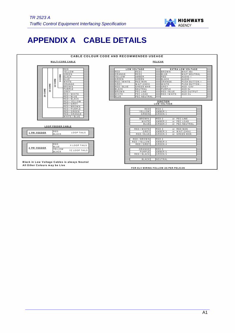
3.1.1 A cable colour code and recommended usage for signal cable is detailed in Appendix A.
3.1.2 The interoperability of halogen and low energy signals is detailed in MCH 1979.
3.2 Vehicle detectors – Above Ground (to TR 2505)
1.4 The power supply shall be 24 V ac ± 20%.
3.3 Vehicle Detectors – Below Ground (to TR 2512)
3.3.1 The power supply shall be 24 V ac or 40 V ac + 13% - 10%.
3.3.2 The detector units shall be connected using either:
♦ An RJ 45 Connector;
♦ Euro Connector; or
♦ Integrated Detector Link.
3.3.3 The detector units shall be housed within the controller by way of a Euro card size detector mounted in the IEC 297 3U rack. The Eurocard edge connector interfaces with a DIN 41612 Type ‘B’ socket. (See TR 2512)
3.4 Pedestrian Kerbside Detectors (to TR 2507)
3.4.1 The power supply shall be 24 V ac ± 20%.
3.4.2 The logic ‘0’ output state shall continuously present a maximum resistance of 50 ohms.
3.4.3 The logic ‘1’ output state shall be as detailed in 2.3.6.
3.4.4 Piezo electric surface mounted kerbside detectors require test pulses from the signal controller to verify that they remain operational in the absence of pedestrian demands. Where these test pulse are required they shall be between 3.5 and 27 V dc with a current source of 10 mA ± 5 mA.
3.5 Pedestrian On-Crossing Detectors (to TR 2506)
3.5.1 The power supply shall be 24 V ac ± 20%.
3.6 Nearside Signal and Demand Units (to TR 2511)
3.6.1 Operation at a reduced intensity is a requirement for the nearside signal unit. When required the light output shall be at 15 to 25% of its full brightness. The reduced voltage levels shall be as detailed in 2.7.
3.6.2 Nearside signal units can comprise of:
♦ One unit housing both nearside signal and demand unit, or
♦ Separate nearside signal and demand units
3.6.3 Where power is required from the signal aspect supply to operate push buttons or WAIT indicators, transformers or other devices may need to be used to ensure that only Extra Low Voltage supplies are used within the pedestrian demand unit enclosure.
TR 2523 A Traffic Control Equipment Interfacing Specification
7
3.7 Pedestrian Audible Units (to TR 2509)
3.7.1 The tactile interlock power supply shall be as detailed in 2.8.2. The audible unit shall not draw more than 12 mA from this supply.
3.8 Pedestrian Tactile Units (to TR 2508)
3.8.1 For a power supply internal to the signal controller, the power supply shall be derived from, or controlled by, the signal controller’s supply to the green pedestrian signals.
3.8.2 For a power supply external to the signal controller, a single external power supply only shall provide power to a single tactile unit unless specifically designed otherwise.
3.8.3 A supply of 15 to 30 V dc shall be provided for the tactile unit. The audible unit shall be limited to 12 mA from this supply.
3.8.4 An Interlock shall be provided that corresponds to the Vehicle red signal monitor function such that the supply out shall be inhibited when a fault condition is present.
3.9 Accommodation of Ancillary Equipment
3.9.1 A mounting rack of full or half width to IEC 297 Standard (w483mm×h222mm×d306mm) shall be provided within the controller. The depth of 306mm does not include an additional provision of 26 mm in front of any ancillary equipment.
3.9.2 Access to the rear of any ancillary equipment unit shall be provided when the unit is fitted in the position allocated within the controller cabinet. Where there is no direct access to the rear the unit shall be mounted on sliding rails or other means to facilitate access.
TR 2523 A Traffic Control Equipment Interfacing Specification
8
4 URBAN TRAFFIC CONTROL (UTC) 4.1 General
4.1.1 In the UTC mode of control, the permanent traffic signal controller shall be controlled either by a remote computer, via a data transmission system, or by a MOVA unit, which may be either integral to the controller or installed as an ancillary item and connected to the signal controller via the UTC interface.
4.1.2 More details on UTC, including SCOOT (Split, Cycle and Offset Optimisation Technique) can be found in MCE 0360. MCH 1542 provides more details on MOVA (Microprocessor Optimised Vehicle Actuation).
4.1.3 This section details the operation and facilities of the permanent signals controller to be compatible with existing UTC systems under remote computer control and with existing MOVA equipment under local control.
4.1.4 The facilities described in this section shall be available in any combination, as required by the Purchaser. The controller shall operate as indicated by this section when used in a UTC system to MCE 0360.
4.1.5 Controllers that become part of a UTC system shall comply with one of the following options.
a) Option 1 permits force signals to behave as though simultaneous demand bits were transmitted.
b) Option 2 allows a measure of vehicle-actuated operation during the UTC cycle.
4.1.6 When operating under UTC, the Controller shall operate in a stage-based manner, whereby it is necessary to allocate phases to stages, such allocations being conditioned by the traffic requirements and safety constraints.
4.1.7 Designations of control/reply signals (see clauses 4.4 and 4.5) are those commonly used. Others may be used where a need is identified.
4.1.8 Integral MOVA may be used as a fall–back mode for UTC.
4.1.9 The controller shall not accept a change of the control signal condition presented at the OTU/controller interface until the signal condition has persisted for two successful controller-scans to ensure valid data. The time between scans shall not exceed 400 milliseconds. The controller shall not accept any control signals shorter than 10 milliseconds. The controller reply signals presented at the OTU/controller interface shall be updated simultaneously at least once per controller scan.
4.2 OTU/Controller Interface – Ancillary
4.2.1 The Controller shall be linked to the transmission system by an OTU that has been designed to MCE 0312, which is normally housed within the Controller cabinet.
4.2.2 Control and reply information between an OTU and the signal controller shall be presented at the OTU/Controller interface.

TR 2523 A Traffic Control Equipment Interfacing Specification
9
Interface Signal Conditions
4.2.3 The logic conditions are defined as follows:
Method 1 a) a logic condition ‘0’ represents
the inactive state and, where relevant, will be the closed circuit condition across the controller input terminals and the closed circuit condition across the controller output terminals of the OTU/Controller interface;
b) a logic condition ‘1’ represents the active state and, where relevant, will be the open circuit condition across the controller input terminals, and the open circuit condition across the controller output terminals of the OTU/Controller interface.
4.2.4 This may present a compatibility problem with some existing ancillary equipment. As an option it may therefore be possible to configure the logic conditions as per method 2.
Method 2 a) A logic ‘0’ condition represents
the active state and, where relevant, will be the closed circuit condition across the controller input terminals and the open circuit condition across the controller output terminals of the OTU/Controller interface.
b) A logic ‘1’ condition represents the idle state and, where relevant, will be the open circuit condition across the controller input terminals, and the closed circuit condition across the controller output terminals of the OTU/Controller interface.
4.3 OTU/Controller Interface – Integral
4.3.1 It may be possible for a manufacturer to supply equipment with the OTU function integrated into the controller logic. Such an integrated system will interface to the transmission lines subject to the relevant Clauses of MCE 0312 in particular chapter 4 (except for clause 4.12), and chapter 5. The OTU function need not interface to all the variants of data transmission formats in current use.
4.3.2 When the integrated OTU facility is used, a manufacturer shall be able to provide facilities for switched signs and/or remote pelican controllers or any other item of equipment controlled via the interface.
Note: With a separate OTU such signals would be derived directly from the OTU input/output interface in accordance with the Standard Interface requirements defined in clauses 2.2 and 2.4.
4.3.3 It shall be possible to configure control and reply bits between the OTU and the controller. This may be via a handset.
4.4 Control Signals (Originating externally to the controller)
4.4.1 It shall not be possible for any single control signal or for any combination of control signals in any sequence, to modify the duration of any minimum green period or fixed intergreen period.
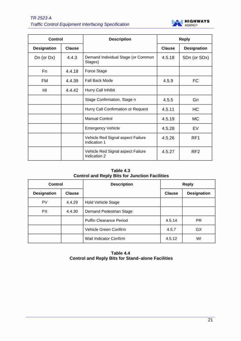
4.4.2 Table 4.3 refers to junction control functions; Table 4.4 refers to stand–alone functions and Table 4.2 details functions that are common to both.

TR 2523 A Traffic Control Equipment Interfacing Specification
10
Stage Demand Bits DX and D1, D2 etc.
4.4.3 Common Demand Bit (DX). Condition ‘1’ on the DX control bit shall simulate the operation of detector inputs to the controller from detector equipment on vehicle actuated stages and, where specified, on pedestrian stages by simulating demands or demands/extensions for selected phases associated with each of the stages. Exceptionally, (where specified), certain stages may be excluded from this common demand. DX shall not inhibit the operation of the pedestrian push buttons and/or vehicle or pedestrian detectors.
4.4.4 DX Bit and Other Methods of Control. The DX function shall be fitted to all controllers equipped for the UTC method of control and may operate in any mode.
4.4.5 DX and Option 1 Strategy. For controllers operating the UTC method of control to OPTION 1 strategy, DX shall simulate the operation of all detectors. Under other methods of traffic control DX will simulate the operation of detectors on all vehicle actuated stages and, (where specified), of pedestrian demands.
4.4.6 DX and Option 2 Strategy. For controllers operating to OPTION 2 strategy, DX will simulate the operation of detectors on all vehicle-actuated stages and (where specified), of pedestrian demands under either remote computer control or local operation. Means shall be provided of allocating phase detectors to stages.
4.4.7 DX Operation and VA Operation. The Common Demand bit (DX) shall cause each of the stages called by DX to run for its fixed maximum. The continuous presence of DX shall cause the controller to serve the demanded stages in cyclic order.
4.4.8 DX Operation with F Bits (optional). With this option some stages will be declared demand dependent. Such demand dependent stages will only respond to an F bit either when a local demand exists or when a DX bit is sent with the F bit. E.g. F1 = go to stage 1 if a local demand for stage 1 exists; F1.DX = forces controller to stage 1.
4.4.9 Demand Bits and the Detector Fault Monitor. The Common Demand bit (DX) and the individual stage demand bits D1, D2 etc shall not influence the Detector Fault Monitor.
4.4.10 Individual Computer Stage Demand Bits (D1, D2 etc). Where specified in the Works Specification certain stages may be demand dependent each with its own demand bit.
4.4.11 Logic Conditions for Stage Demand Bits. Condition ‘1’ on a stage demand bit (D1, D2 etc.) shall simulate the operation of a detector by simulating the demands and extensions for selected phase(s) associated with the stage.
4.4.12 Insertion of Stage Demands. Stage demands may be derived from:
a) Common Demand Bit (DX);
b) Individual Stage Demand Bits (D1, D2 etc);

TR 2523 A Traffic Control Equipment Interfacing Specification
11
c) Pedestrian Push Buttons (with pedestrian detection in the case of Puffins);
d) Vehicle Detectors.
4.4.13 Non–Demand Dependent Stage. In the UTC method of control the non–demand dependent stages (i.e. stages not covered by DX, or D1, D2 etc) will behave as though a demand signal has been received simultaneously with the corresponding force signal. (This is to cater for Option 1 strategy.)
Latching and Non–Latching Demands.
4.4.14 Computer stage demands (DX, D1, D2, etc) may be latched or not latched in accordance with the site specific requirements and will simulate street detection with the following exceptions:
a) timing delays associated with the delayed call/cancel facilities are not applicable to computer demands, (i.e. the presence of a computer demand associated with the call/cancel facility shall cause an immediate demand for the associated phase to be registered). Removal of the computer demand shall remove the associated phase demand unless this is also generated by street detection;
b) the condition where a turning phase demand is active only if another selected phase demand is present, shall not be overridden by a UTC computer calling for the stage which runs the turning phase.
4.4.15 Servicing of Stage Demands. The servicing of demands shall be subject to traffic movement constraints specified in TR 2500 and to the presence of force bits.
4.4.16 When there are no force bits present, the controller will revert to the fall–back method of control as required by TR 2500.
4.4.17 A demand for a stage may either extend that stage or request the stage to run according to the following provisions:
a) a VA stage already having right–of–way:
i) if an extendable stage already has right–of–way, a demand shall hold the vehicle extension timer reset and, on release of the demand, the vehicle extension timer associated with the stage shall become operative;
ii) if at any time the maximum timers for the relevant phases in the stage expire then the required stage change away from this stage shall occur and the demand shall then be treated as a demand for a stage not having right–of–way. Only the maximum timers for those phases, which do not run in the next stage, are regarded as relevant.
b) Stages not having right–of–way:
i) If a stage does not have right–of–way, a demand for the stage shall request the stage.
TR 2523 A Traffic Control Equipment Interfacing Specification
12
Force Bits (F1, F2 etc.)
4.4.18 The controller shall assume the UTC method of traffic control within 400 milliseconds of a force bit being accepted or, conversely, in the absence of force bits, the controller shall revert to the fall–back method of traffic control within 400 milliseconds. This time may be additional to the time required to ensure valid data, as detailed by clauses 4.2 and 4.3.
4.4.19 The forced change to the selected stage shall not contravene any restrictions upon stage-to-stage movements that may be imposed by the requirements of TR 2500.
4.4.20 Condition ‘1’ shall force the controller to make an immediate change to the selected stage or shall hold a selected stage subject to the following conditions:
a) if the selected stage does not have right–of–way then condition ‘1’ on the force bit for that stage, and no other, shall cause a forced change to that stage provided that a demand exists or is assumed to exist for the stage;
b) if the controller is in an intergreen or a minimum green period, the change to the selected stage shall be deferred until the expiry of the minimum green period, provided that the force condition still exists;
c) if the selected stage has already appeared, condition ‘1’ on the force bit for that stage shall reset the phase maximum timers and hold that stage for so long as the condition ‘1’ is received, provided that gap changes to another demanded stage are prevented by vehicle extensions (e.g. either by control demand signals or from local detectors).
4.4.21 Where called for in the Works Specification, it shall be possible for a stage to behave as though a control demand signal (D1, D2, etc) has been received simultaneously with the corresponding force signal, even though no such demand signal has been transmitted.
4.4.22 A facility shall be provided to time–out force bits such that if an F bit(s) is unchanged for longer than a predetermined time the controller shall revert to the fall–back method of control. This time shall be preset at a value in the range between 120 and 300 seconds, and adjustable in incremental steps no more than 10 seconds. If no time is specified then a default of 200 seconds shall be set. This facility shall not be provided if the MOVA Take Over (TO) but set to ‘1’.
4.4.23 If condition ‘1’ is received on the force bits for more than one stage simultaneously then the controller shall respond as in Table 4.1.
Switch Facility (SF1, SF2, etc.)
4.4.24 Condition ‘1’ shall switch a specified miscellaneous facility, (e.g. a regulatory traffic sign). Interfacing directly to the specified OTU output terminal or via the controller may provide this facility.
TR 2523 A Traffic Control Equipment Interfacing Specification
13
4.4.25 If required by the Works Specification this facility may be associated with a nominated stage or phase so that a sign will only switch ‘ON’ at the start of the nominated stage and shall only be extinguished at the start of a nominated stage or phase green.
4.4.26 If required by the Works Specification the command to switch the facility shall remain in the ‘1’ or the ‘0’ states for a period of between 7 and 10 seconds before the facility is switched on or off. Where the switching action is associated with a stage the time period shall have expired before the start of the stage for the switching action to take place.
4.4.27 The condition ‘1’ shall be the fall back condition and where relevant should be associated with the safe state of the sign as defined in the Works Specification.
4.4.28 Where this facility is used to control a sign, phase-aspect drive equipment may be used for this purpose.
Hold Vehicle (PV)
4.4.29 Condition ‘1’ shall prevent the appearance of the pedestrian stage by the imposition of a ‘hold’ condition on the vehicle stage. All pedestrian demands which have not been served, or which occur during the ‘hold’ period, shall be stored and allowed to mature in a normal manner when the PV signal ceases.
Pedestrian Demand (PX)
4.4.30 Condition ‘1’ shall demand the pedestrian phase. This facility should function even if the output from the kerbside detector is inactive.
Solar Switch Override (SO)
4.4.31 Condition ‘1’ shall switch the traffic signals to the non–dimmed condition, overriding the Solar Switch.
4.4.32 Condition ‘0’ shall not override the solar switch.
CLF Group Timer Synchronisation Signal (SG)
4.4.33 Receipt of an external signal, having the series message format ‘1, 0, 1’ (received over three consecutive transmission message cycles), shall cause the CLF to commence the relevant plan cycle timing from the start of the first group within 1 second ±5% of the ‘0’ to ‘1’ transition of the synchronising message. The Group Timer synchronising signal shall take effect at the receipt of the second ‘1’ providing the Group Timer synchronising signal has been correctly received.
4.4.34 The synchronisation request shall not be accepted if the duration of each ‘1, 0, 1’ bit is not 1 second ± 400 ms.
Signal Aspect On/Off (LO)
4.4.35 Where a condition ‘1’ exists for a minimum of 10 seconds, the signals shall switch on in accordance with the Start Up Sequence.. Where a condition ‘0’ is present for a minimum of 10 seconds, the signals shall switch off during a nominated stage, provided that all minimum running periods have expired.
TR 2523 A Traffic Control Equipment Interfacing Specification
14
Local Linking Inhibit (LL)
4.4.36 Condition ‘1’ shall inhibit local linking between parallel stage streams, or other local links as specified in the Works Specification.
Time Synchronisation Signal (TS)
4.4.37 Receipt of an external signal, having the series message format ‘1, 0, 1’ (received over three consecutive transmission message cycles), shall cause the controller clock to reset to 00:00 hours or other configured time to the nearest ½ second. The controller synchronising signal shall take effect at the receipt of the second ‘1’.
4.4.38 The synchronisation shall not respond to the message format if the duration of each ‘1, 0, 1’ bit lasts for less than one second.
Fall Back Selection (FM)
4.4.39 When the signal controller is not in the UTC mode, condition ‘1’ shall inhibit CLF mode and cause the controller to revert a lower priority method of traffic control, e.g. vehicle actuated or fixed time. Condition ‘0’ shall have no effect.
Take Over (TO)
4.4.40 This facility shall allow control to be accepted from a remote source. While the TO bit is set to logic ‘0’ (inactive condition) the controller shall ignore the control bits specified in an associated works specification
4.4.41 Where an ancillary MOVA unit is specified and control is via the UTC interface, control shall only be operational when the Take Over bit (logic condition ‘1’) is present
Hurry Call Inhibit (HI)
4.4.42 Logic condition ‘1’ shall inhibit Hurry Call Requests.
Transmission Confirm (TC)
4.4.43 The TC bit shall be set to logic condition ‘1’ when a validated control message has been received by the OTU. When the TC bit is set to logic ‘0’ (inactive condition) the controller shall ignore all control data from the OTU.
Close Car Park (CP)
4.4.44 Logic condition ‘1’ shall close the car park.
4.5 Reply Signals
4.5.1 The signal controller shall return reply signals via the OTU to indicate any of the functions specified below. The appropriate reply signals shall be present in all methods of traffic control. Condition ‘1’ indicates the active facility in all cases.
4.5.2 Table 4.3 refers to junction control functions,
4.5.3 Table 4.4 refers to stand–alone functions and
4.5.4 Table 4.2 details functions that are common to both.
Stage Confirmation (Gn)
4.5.5 Condition ‘1’ confirms that a particular stage, or phase if specified is running.
4.5.6 G1 and G2 shall normally be returned simultaneously to indicate that one of the following has occurred:
a) the mains supply to the signal aspects is off;

TR 2523 A Traffic Control Equipment Interfacing Specification
15
b) manual method of traffic control is either in operation or requested;
c) The traffic controller is switched off;
d) The traffic controller has failed or shut down due to a fault;
e) The interface between the OTU and the controller has been disconnected.
Vehicle Stage Green Confirmation (GX)
4.5.7 Condition ‘1’ confirms that a green signal is displayed to vehicles on a stand–alone controller. When the signals are not on stage green, or when the controller or signals are switched off, the indication returned shall be condition ‘0’.
Detector Fault Monitor (DF)
4.5.8 Condition ‘1’ confirms that the detector fault monitor system indicates a detector failure.
Fall Back Selection Confirmation (FC)
4.5.9 Condition ‘1’ confirms that the Fall Back selection facility has been introduced.
Switch Facility Confirmation (SCn)
4.5.10 Condition ‘1’ confirms that a particular Switch Facility has been introduced.
Hurry Call Confirmation or Request (HC)
4.5.11 Condition ‘1’ confirms that a Hurry Call request has been requested or is being actioned, as specified in an associated Works Specification.
Wait Indicator Confirm (WI)
4.5.12 Condition ‘1’ confirms that the WAIT indicator (Pelican) or the Pedestrian Demand Accepted (Puffin) is energised at stand-alone crossings.
Pedestrian Stage Green Confirm (PC)
4.5.13 Condition ‘1’ confirms that the pedestrian green signal is energised. Condition ‘0’ shall be given when the controller or signals are switched off. This can apply to junction or stand–alone facilities.
Puffin Pedestrian Clearance Period (PR)
4.5.14 Condition ‘1’ confirms that the pedestrian clearance period is operative. Condition ‘0’ shall be given when the controller or signals are switched off.
CLF Group Timer Synchronisation Confirm (CG)
4.5.15 A signal shall be returned to the OTU/controller interface when the synchronising signal has been correctly received and actioned. This reply signal (condition ‘1’) shall be normally maintained for a period of 3 seconds ±1 second or as specified in the Works Specification.
4.5.16 As an option the CG bit may confirm the time of day and day of week in the controller clock. The CG bit may be set to condition ‘1’ (active) at a predetermined period after the controller synchronisation time. The length of time the signal is held active shall indicate the day of the week as follows:
Sunday 3 seconds
Monday 5 seconds
Tuesday 7 seconds

TR 2523 A Traffic Control Equipment Interfacing Specification
16
Wednesday 9 seconds
Thursday 11 seconds
Friday 13 seconds
Saturday 15 seconds
Group 1 Indication (GR1)
4.5.17 That CLF is in the first group. This reply signal (condition ‘1’) shall be maintained for a period of three seconds ±1 second.
Stage Demands (SDn)
4.5.18 Condition ‘1’ confirms that a demand exists for a stage.
Manual Control (MC)
4.5.19 Condition ‘1’ confirms that Manual Control is either in operation or requested as specified in an associated Works Specification.
Controller Fault Indication (CF)
4.5.20 Condition ‘1’ confirms that an entry is in the system fault log.
Signal aspects Extinguished Indication (LE)
4.5.21 That the mains supply to the signal aspects has been interrupted by:
a) operation of the signal aspect switch, or;
b) the signal aspect fuse being blown, or;
4.5.22 the controller mains supply being off (only in the case of a separately powered OTU).
4.5.23 This may include part time signal operation.
Remote Reconnect (RR)
4.5.24 As an optional facility, the controller may be released from remote control due to manual intervention and should be specified in an associated Works Specification. Condition ‘1’ shall request release and condition ‘0’ shall be returned to request re–establishment of remote control (see Clause 4.5.19).
Signal aspect Failure (LFn)
4.5.25 Condition ‘1’ confirms that one or more traffic signal aspects have failed, where these are monitored.
Vehicle Red Signal aspect Failure (RF1)
4.5.26 Condition ‘1’ confirms that at least one vehicle red signal aspect has been accepted as failed where these are monitored for Part Time or Pedestrian Audible/Tactile Control.
Vehicle Red Signal aspect Failure (RF2)
4.5.27 Condition ‘1’ confirms that a second vehicle red signal aspect has been accepted as failed on an approach, or a vehicle red signal aspect feed has failed where these are monitored for Part Time or Pedestrian/Audible Tactile Control or the Red Signal aspect monitor has failed.
Emergency Vehicle (EV)
4.5.28 Condition ‘1’ confirms that the controller is servicing a priority call, other than a hurry call.
Vehicle Count (VC)
4.5.29 A count of the number of vehicle pulses scaled by a predetermined scale factor.

TR 2523 A Traffic Control Equipment Interfacing Specification
17
Queue Detector (VQ)
4.5.30 Condition ‘1’ confirms that the Vehicle Queue Detector indicates a queue state.
Car Park Occupancy Threshold Exceeded (CA)
4.5.31 Condition ‘1’ confirms that the car park occupancy threshold is exceeded.
Queue at Car Park Reservoir (CR)
4.5.32 Condition ‘1’ confirms that a queue state exists at the car park entry reservoir.
Car Park Closed (CL)
4.5.33 Condition ‘1’ confirms that the car park is closed.
Car Park Information (CSn)
4.5.34 Condition ‘1’ indicates the state of specified signs associated with the car park.
Handset Connected (TF)
4.5.35 Condition ‘1’ confirms that the handset equipment is connected to the Terminal interface.
SCOOT Detector Output Presence (VSn)
4.5.36 Condition ‘1’ is the active output state on a SCOOT detector.
Note: These are four sample bits/second/ detector.
Cabinet Door Open (CO)
4.5.37 Condition ‘1’ confirms that the cabinet door is open.
4.6 UTC Control of Stage Streams
4.6.1 Stage streams shall be controlled by UTC according to one of the following 3 options, any of which it shall be possible to specify.
Option A, Master–Master Linking
4.6.2 Control shall be achieved by separate forces to each stream. For the computer method of traffic control to operate on any stream, force bits are required to be present for all streams. If force bits for any of the streams are absent, the controller will revert to the standby method of traffic control except when control bit, LL, is present.
Option B, Master–Slave Linking
4.6.3 Only the master stream is required to be computer controlled. The slave streams shall either be computer controlled or under the control of master–slave cross–linking. Under this option the computer method of traffic control does not operate if force bits for the master stage stream are absent, except when control bit, LL, is present.
Option C, Unlinked
4.6.4 Streams with no cross–linking constraints shall have completely independent computer control for each stream. The method of traffic control of one stream shall have no effect on the method of control of any other stream.

TR 2523 A Traffic Control Equipment Interfacing Specification
18
Stage Stream Routining
4.6.5 Where stage streams are cross–linked to an extent which would inhibit the normal UTC night–time routining, it shall be possible (subject to safety considerations) to arrange for specific cross–linking to be disabled. This shall be achieved by the use of a specific local linking inhibit bit (LL) sent by the computer. It shall also be possible for the receipt of LL with force bits for one stage stream to modify other cross–linking constraints if specified.

TR 2523 A Traffic Control Equipment Interfacing Specification
19
Current Stage Condition Option 2 Option 1
1. No demands
2. Demand (Ext) for current stage
Hold current stage indefinitely.
3. No demand for current stage, demand for other forced stage(s).
Change to next forced stage in cyclic order.
Controller already on one of stages for which a force bit is being received
4. Demands for stage(s) other than forced stage(s).
Change(s) to demanded stage(s).
Hold current stage Indefinitely.
1. No demands. Hold current stage.
If both forced stages are demand dependent – hold current stage. If either of the forced stages is not demand dependent then demands are assumed and a move to the next forced (and demanded) stage in cyclic order is made, and is then held indefinitely.
2. Demand for one of the forced stages.
Move to demanded stage and hold.
Move to next forced (and demanded) stage in cyclic order and hold.
Controller not already on one of the stages for which a force bit is being received.
3. Demand for two or more forced stages.
Move to next of the forced stages in cyclic order and hold.
Move to next of the forced stages in cyclic order and hold.
4. Demands for stages other than forced stages.
Move to demanded stages in cyclic order. (Dependent on traffic movement constraints.)
If both forced stages are demand dependent, hold current stage.
If either of the forced stages is not demand dependent then move to the next forced (and demanded) stage in cyclic order and hold.
Table 4.1 – Simultaneous Force Bits

TR 2523 A Traffic Control Equipment Interfacing Specification
20
Control Reply
Designation Clause Description
Clause Designation
SFn 4.4.24 Switch Facility 4.5.10 SCn
SO 4.4.31 Solar Override
SG 4.4.33 CLF Group Timer Synchronisation 4.5.15 CG
LO 4.4.35 Signal aspects On/Off 4.5.21 LE
LL 4.4.36 Local Link Inhibit
TS 4.4.37 Time Switch Synchronisation to Stored Value (or Nearest ½ Min)
TO 4.4.40 Take Over
TC 4.4.43 Transmission Confirm
CP 4.4.44 Close Car Park 4.5.33 CL
Detector Fault Monitor 4.5.8 DF
CLF Group Timer in First Group 4.5.17 GR1
Remote Reconnect 4.5.24 RR
Entry in Controller Fault Log 4.5.20 CF
Handset Connected 4.5.35 TF
Signal aspect Fault 4.5.25 LFn
Car Park Occupancy Threshold Exceeded 4.5.31 CA
Pedestrian Green Confirm 4.5.13 PC
Queue Detector Presence 4.5.30 VQ
Detector Vehicle Count 4.5.29 VC
Car Park Information 4.5.34 CSn
Queue at Car Park Entry Reservoir 4.5.32 CR
SCOOT Detector Presence 4.5.36 Vsn
Cabinet Door Open 4.5.37 CO
Table 4.2 Control and Reply Bits for either Junction or Stand–alone Facilities
TR 2523 A Traffic Control Equipment Interfacing Specification
21
Control Reply
Designation Clause
Description
Clause Designation
Dn (or Dx) 4.4.3 Demand Individual Stage (or Common Stages)
4.5.18 SDn (or SDx)
Fn 4.4.18 Force Stage
FM 4.4.39 Fall Back Mode 4.5.9 FC
HI 4.4.42 Hurry Call Inhibit
Stage Confirmation, Stage n 4.5.5 Gn
Hurry Call Confirmation or Request 4.5.11 HC
Manual Control 4.5.19 MC
Emergency Vehicle 4.5.28 EV
Vehicle Red Signal aspect Failure Indication 1
4.5.26 RF1
Vehicle Red Signal aspect Failure Indication 2
4.5.27 RF2
Table 4.3 Control and Reply Bits for Junction Facilities
Control Reply
Designation Clause
Description
Clause Designation
PV 4.4.29 Hold Vehicle Stage
PX 4.4.30 Demand Pedestrian Stage
Puffin Clearance Period 4.5.14 PR
Vehicle Green Confirm 4.5.7 GX
Wait Indicator Confirm 4.5.12 WI
Table 4.4 Control and Reply Bits for Stand–alone Facilities

TR 2523 A Traffic Control Equipment Interfacing Specification
22
5 NORMATIVE REFERENCES 5.1 Where undated references are listed, the latest issue of the publication shall apply.
British Standards
5.2 The British Standards Institution, London, publishes British Standards.
Contact: +44 (0) 1344 404 429
BS 7671 Requirements for Electrical Installations
Specifications
5.3 Specifications are published by the Highways Agency and can be downloaded from the Plans Registry web site at http://www.tssplansregistry.org/homepage.htm.
Contact: +44 (0) 117 372 8300
TR 2500 Specification for Traffic Signal Controller.
TR 2505 Specification for Above Ground Vehicle Detector Systems For Use At Permanent Traffic Signal Installations
TR 2506 Specification for Above Ground On-crossing Pedestrian Detection System
TR 2507 Specification for Kerbside Pedestrian Detection Systems for use at Pedestrian Crossings
TR 2508 Performance Specification for Tactile equipment for use at Pedestrian Crossings
TR 2509 Performance Specification for Audible Equipment for use at Pedestrian Crossings.
TR 2511 Specification for Nearside Signal and Demand Unit
TR 2512 Performance Specification for Below Ground Vehicle Detection Equipment
MCE 0312 Data Transmission Traffic Control System
MCE 0360 Urban Traffic Control – Functional Specification
MCH 1542 Installation Guide for MOVA
MCH 1979 Guide to Traffic Control Signal Failure & Reporting Techniques

TR 2523 A Traffic Control Equipment Interfacing Specification
23
Other Publications
5.4 Other publications can be obtained from the Stationary Office:
Contact: +44 (0)20 7242 6393
Web address: http://www.tso.co.uk
IEC 297 Dimensions of Mechanical Structures of the 482.6 mm (19”) Series
TR 2523 A Traffic Control Equipment Interfacing Specification
24
6 HISTORY
TR 2523 Issue A September 2005
Approval of this document for publication is given by the undersigned.
Traffic Signals and Road Lighting Safety
Zone 2/17E Temple Quay House 2 The Square Temple Quay Bristol BS1 6HA
Mike Smith Team Manager Traffic Signals & Road Lighting Safety
TR 2523 A Traffic Control Equipment Interfacing Specification
A1
APPENDIX A CABLE DETAILS
R E D Y E LL O WG R E E NB LA C KB LU EW H IT EO R A N G EB R O W NP U R P L EG R E YR E D / W H IT ER E D / B LU ER E D / B LA C KR E D / Y E LL O WR E D / G R E YR E D / B R O W NR E D / P U R P L ER E D / G R E E NR E D / O R A N G EW H IT E / B LU E
oro ro r
o rR E D orB L A C K or
R E D 4A M B E R 4
R E D G R E E N 4B L U EY E LLO W R E D 5B L A C K A M B E R 5
G R E E N 5
N E U T R A LB la c k in L o w V o ltag e C a b le s is a lw a ys N e u tra lA ll O th e r C o lo u rs m a y b e L ive
P E L IC AN
F O R E L V W IR IN G F O L L O W AS P E R P E L IC AN
P E C N E U T R A LP E C LO A DP E C L IN ER E D 2
G R E E N 1A M B E R 1
L O W V O L T AG E
R E D 1
G R E E N 2A M B E R 2
G R E E NY E LL O W
R E D
G R E E N 3 G R E E N M A NW A IT (24 0v)A M B E R 3R E D M A NR E D 3
B L A C K
O R A N G EP U R P LE
R E D / B L A C K
R E D / B R O W NR E D / Y E LL O W
R E D / G R E Y
R E D / W H IT EG R E Y
R E D / B LU E
B R O W N W H IT E
B LU E
JU N C T IO N
O R A N G EW H IT EG R E YP U R P LE
A G D +2 4VA G D 0vA G D O U T P U TA G D O v
A U D IO +A U D IO -
B R O W NB LU ER E DB LA C K
R E DO R A N G EY E L LO WG R E E NR E D / W H IT EG R E YR E D / B LU EB LA C K
R E D M A NW A IT (24 0V )
E X T R A L O W V O L T A G E
P U S H B U T T O N +P U S H B U T T O N -
R E D / B LU ER E D / W H IT E
W A IT 4 8vW A IT N E U T R A L
B R O W NW H IT E
P E C N E U T R A L
L O W V O L T AG E
G R E E N M A NN E U T R A LP E C L IN EP E C LO A D
A M B E RG R E E N
B LU E
C A B L E C O L O U R C O D E A N D R E C O M M E N D E D U S E A G E
M U L T I-C O R E C AB L E
1 'P R ' F E E D E R
8 C
OR
E
12 C
OR
E
16 C
OR
E
20 C
OR
E
R E D 1R E D 2
2 'P R ' F E E D E R
L O O P F E E D E R C AB L E
Y Z LO O P T A IL S
LO O P T A IL S
X L O O P T A ILS