Traffic gr ooming in WDM ring networks to minimize the ...
18
UNCORRECTED PROOF OSN: 8 DTD 5 pp. 1–18 (col. fig: NIL) ARTICLE IN PRESS Optical Switching and Networking xx (xxxx) xxx–xxx www.elsevier.com/locate/osn Traffic grooming in WDM ring networks to minimize the maximum electronic port cost Bensong Chen ∗ , George N. Rouskas, Rudra Dutta Department of Computer Science, North Carolina State University, Raleigh, NC 27695-7534, United States Received 20 July 2004; received in revised form 7 December 2004; accepted 31 January 2005 Abstract We consider the problem of traffic grooming in WDM ring networks. Traffic grooming is a variant of the well-known logical topology design problem, and is concerned with the development of techniques for combining low speed traffic components onto high speed channels in order to minimize network cost. Previous studies have focused on aggregate representations of the network cost. In this work, we consider a Min–Max objective, in which it is desirable to minimize the cost at the node where this cost is maximum. Such an objective is of high practical value when dimensioning a network for unknown future traffic demands and/or for dynamic traffic scenarios. We present new theoretical results which demonstrate that traffic grooming with the Min–Max objective is NP-complete even when wavelength assignment is not an issue. We also present new polynomial-time traffic grooming algorithms for minimizing the maximum electronic port cost in both unidirectional and bidirectional rings. We evaluate our algorithms through experiments with a wide range of problem instances, by varying the network size, number of wavelengths, traffic load, and traffic pattern. Our results indicate that our algorithms produce solutions which are always close to the optimal and/or the lower bound, and which scale well to large network sizes, large number of wavelengths, and high loads. We also demonstrate that, despite the focus on minimizing the maximum cost, our algorithms also perform well in terms of the aggregate electronic port cost over all ring nodes. © 2005 Published by Elsevier B.V. 1. Introduction 1 Wavelength division multiplexing (WDM) technol- 2 ogy has the potential to satisfy the ever-increasing 3 bandwidth needs of network users on a sustained basis. 4 ∗ Corresponding author. E-mail addresses: [email protected] (B. Chen), [email protected] (G.N. Rouskas), [email protected] (R. Dutta). 1573-4277/$ - see front matter © 2005 Published by Elsevier B.V. doi:10.1016/j.osn.2005.01.002 In WDM networks, nodes are equipped with opti- 5 cal cross-connects (OXCs) or optical add–drop multi- 6 plexers (OADMs), devices which can optically switch 7 wavelengths, thus making it possible to establish light- 8 path connections between pairs of network nodes. The 9 set of lightpaths defines a logical topology, which can 10 be designed to optimize some performance measure 11 for a given set of traffic demands. The logical topol- 12 ogy design problem has been studied extensively in 13 the literature. Typically, the traffic demands have been 14
Transcript of Traffic gr ooming in WDM ring networks to minimize the ...

UNCORRECTE
D PRO
OF
OSN: 8 DTD 5 pp. 1–18 (col. fig:NIL )
A R T I C L E I N P R E S S
Optical Switching and Networking xx (xxxx) xxx–xxx
www.elsevier.com/locate/osn
Traffic grooming in WDM ring networks to minimize themaximum electronic port cost
Bensong Chen∗, George N. Rouskas, Rudra Dutta
Department of Computer Science, North Carolina State University, Raleigh, NC 27695-7534, United States
Received 20 July 2004; received in revised form 7 December 2004; accepted 31 January 2005
Abstract
We consider the problem of traffic grooming in WDM ring networks. Traffic grooming is a variant of the well-known logicaltopology design problem, and is concerned with the development of techniques for combining low speed traffic componentsonto high speed channels in order to minimize network cost. Previous studies have focused onaggregaterepresentations of thenetwork cost.In this work, we consider aMin–Max objective, in which it is desirable to minimize the cost at the node wherethis cost is maximum. Such an objective is of high practical value when dimensioning a network for unknown future trafficdemands and/or for dynamic traffic scenarios. We present new theoretical results which demonstrate that traffic grooming withthe Min–Max objective is NP-complete even when wavelength assignment is not an issue. We also present new polynomial-timetraffic grooming algorithms for minimizing the maximum electronic port cost in both unidirectional and bidirectional rings. Weevaluate our algorithms through experiments with a wide range of problem instances, by varying the network size, number ofwavelengths, traffic load, and traffic pattern. Our results indicate that our algorithms produce solutions which are always closeto the optimal and/or the lower bound, and which scale well to large network sizes, large number of wavelengths, and highloads. Wealso demonstrate that, despite the focus on minimizing the maximum cost, our algorithms also perform well in termsof the aggregate electronic port cost over all ring nodes.© 2005 Published by Elsevier B.V.
1. Introduction1
Wavelength division multiplexing (WDM) technol-2
ogy has the potential to satisfy the ever-increasing3
bandwidth needs of network users on a sustained basis.4
∗ Corresponding author.E-mail addresses:[email protected] (B. Chen),
[email protected] (G.N. Rouskas), [email protected](R. Dutta).
1573-4277/$ - see front matter © 2005 Published by Elsevier B.V.doi:10.1016/j.osn.2005.01.002
In WDM networks, nodes are equipped withopti- 5
cal cross-connects(OXCs) oroptical add–drop multi- 6
plexers(OADMs), devices which can optically switch 7
wavelengths, thus making it possible to establishlight- 8
pathconnections between pairs of network nodes. The 9
set of lightpaths defines alogical topology, which can 10
be designed to optimize some performance measure11
for a given set of traffic demands. The logical topol- 12
ogy design problem has been studied extensively in13
the literature. Typically, the traffic demands have been14

UNCORRECTE
D PRO
OF
A R T I C L E I N P R E S S2 B. Chen et al. / Optical Switching and Networking xx (xxxx) xxx–xxx
OSN: 8
expressed in terms of whole lightpaths, while the met-1
ric of interest has been the number of wavelengths, the2
congestion (maximum traffic flowing over any link),3
or a combination of the two. The reader is referred4
to [4] for a survey and classification of relevant work.5
Further, since the bandwidth of a single wavelength6
channel is (and is expected to be in the future) realis-7
tically far more than that of individual traffic needs,8
electronic TDM multiplexing must be applied to9
efficiently utilize bandwidth; but the line terminating10
equipment (LTE) required to do so is a costly net-11
work component. These observations give rise to the12
concept oftraffic grooming[3,6,10,14], a variant of13
logical topology design, which is concerned with the14
development of techniques for combining lower speed15
components onto wavelengths in order to minimize16
network cost. For a surveyand classification of rele-17
vant work, see [6].18
Most studies in literature concentrate on some19
aggregate representation of the LTE cost. That is,20
the objective to be minimized is usually expressed21
as the sum, over all network nodes, of the LTE22
cost at each individual node. While a metric that23
accounts for the network-wide LTE cost is important,24
minimizing the total cost in the network without25
imposing any bound on the cost of individual nodes26
may result in a solution in which some nodes27
end up with a (very) large amount of LTE while28
some others end up with only a small amount of29
LTE. Such a solution has a number of undesirable30
properties. First, a node that requires a large amount31
of LTE may be too expensive or even impractical to32
deploy (e.g., due to high interconnection costs, high33
power consumption, or space requirements). Second,34
the resulting network can be highly heterogeneous35
in terms of the capabilities of individual nodes,36
making it difficult to operate and manage. Third, and37
more important, asolution minimizing the total LTE38
cost can be extremely sensitive to the assumptions39
regarding the traffic pattern, as previous studies [5]40
have demonstrated. Specifically, a solution that is41
optimal for a given set of traffic demands may be far42
awayfrom optimal for a different such set. Since LTE43
involve expensive hardware devices that are difficult44
to move from one node to another on demand, an45
approach that attempts to minimize total LTE cost may46
not be appropriate for dimensioning a network unless47
the network operator has a clear picture of traffic48
demands far into the futureand these traffic demands 49
are unlikely to change substantially over the life of the 50
network. 51
In this work, we consider a variant of the traffic 52
grooming problem in which the objective is to mini- 53
mize the LTE cost at the node where this cost is maxi-54
mum. We believe that a Min–Max objective, such as 55
the one we consider in this paper, is of high prac- 56
tical value to network designers and network oper- 57
ators. In particular, an approach that minimizes the58
maximum LTE cost at any network node is likely to 59
be attractive because, from practical design consider-60
ations, all the network nodes are likely to be provi- 61
sioned with identical equipment. Effectively, all nodes 62
will have a cost that is dictated by the node with the 63
maximum LTE. Such a homogeneous network is eas-64
ier to operate, manage and maintain, and is likely to65
be less expensive than a heterogeneous one due to66
the economies of scale that can be achieved when all67
nodes are subject to identical specifications. Further-68
more, such an optimization approach can be of great69
importance to dimensioning the network forunknown 70
and/or dynamic future demands. Specifically, the net- 71
work designer may solve the optimization problem 72
for a wide range of traffic scenarios, and equip each73
node with an amount of LTE equal to the highest so- 74
lution obtained (plus a certainfudge factorfor making 75
the solution future-proof). We also note that a similar 76
approach was taken in [2] in a different context, 77
namely for routing and wavelength assignment in the78
presence of converters. Specifically, an algorithm was79
developed for distributing a number of converters uni- 80
formly across the ring nodes rather than placing them81
at a single hub node; we make use of this algorithm in82
the heuristics we develop in this paper. 83
The paper is organized as follows. InSection 2, 84
we introduce the Min–Max objective we consider. In 85
Section 3, we presentnew theoreticalresults which 86
demonstrate that traffic grooming with the Min–Max 87
objective is an inherently more difficult problem 88
than other subproblems of logical topology design, 89
e.g., wavelength assignment. InSection 4, we present 90
a polynomial-time algorithm for unidirectional ring 91
networks to minimize the maximum LTE cost at any 92
node; the algorithm consists of two distinct parts, 93
one for traffic grooming and one for wavelength 94
assignment. InSection 5we extend the algorithm for 95
bidirectional rings in which the routing of traffic is 96

UNCORRECTE
D PRO
OF
A R T I C L E I N P R E S SB. Chen et al. / Optical Switching and Networking xx (xxxx) xxx–xxx 3
OSN: 8
not predetermined. We present numerical results in1
Section 6, and we conclude the paper inSection 7.2
2. Problem statement3
We study the traffic grooming problem [6] in a4
ring R with N nodes. LetC be the capacity of each5
wavelength, expressed in units of some arbitrary rate6
(e.g., OC3); we will refer to parameterC as the7
grooming factor. Let W be the number of wavelengths8
that each fiber link in the network can support. We9
represent a traffic pattern by a demand matrixT =10
[t(sd)], where integer t(sd) denotes the number of11
traffic streams (each of unit demand) from nodes to12
noded. (We allow the traffic demands to be greater13
than the capacity of a lightpath, i.e., it is possible that14
t(sd) > C for somes, d.) We further assume that15
ring nodes have electronic switching capabilities that16
permitthem to switch traffic between wavelengths that17
terminate/originate locally. Given matrixT , the traffic18
grooming problem involves the following conceptual19
subproblems (SPs):20
(1) logical topology SP:find a setR of lightpaths,21
(2) lightpath routing and wavelength assignment22
(RWA) SP:solve the RWA problem onR, and23
(3) traffic routing SP: route each traffic stream24
through the lightpaths inR.25
We note that the first and third subproblems to-26
gether constitute the grooming aspect of the problem.27
Also, in this context, the numberW of wavelengths28
per fiber link is taken into consideration as a constraint29
rather than as a parameter to be minimized.30
The Min–Max objective we consider in this paper31
is:32
to minimize the maximum number F of33
lightpaths originating from or terminating at34
any node.35
In our cost model, one unit of cost is incurred for each36
lightpath that terminates at, or originates from, a net-37
work node. Thus, this cost metric accurately reflects38
the amount of LTE needed at each network node, and39
thereforeour objective is to minimize the LTE cost40
at the node where it is maximum. Note also that this41
objective is equivalent to minimizing themaximum42
nodal degreein the logical topology. A formulation of43
this problem as an integer linear programming (ILP) 44
problem can be obtained by applying simple modifi- 45
cations to the ILP we present in [6]. 46
3. Complexity results 47
The traffic grooming problem in ring networks 48
is NP-complete since the RWA subproblem in rings 49
is NP-complete. In this section, we prove that the 50
traffic grooming problem in path networks is also NP- 51
complete. Since the RWA problem can be solved in 52
linear time in path networks, our results demonstrate53
that traffic grooming with the Min–Max objective 54
is itself an inherently difficult problem. They also 55
prove that the traffic grooming problem with the 56
Min–Max objective remains NP-complete in rings or 57
other general topologieseven whenfull wavelength 58
conversion is available at the network nodes. 59
Let us consider a network in the form of a 60
unidirectional pathP with N nodes. There is a single 61
directed fiber link from nodei to node i + 1, for 62
each i ∈ {1, 2, . . . , N − 1}. An instance of the 63
traffic grooming problem is provided by specifying 64
a number N of nodes in the path, a traffic matrix 65
T = [t(sd)], 1 ≤ s < d ≤ N, a grooming factor 66
C, a number of wavelengthsW, and agoal F . The 67
problem asks whether a valid logical topology may be 68
formed on the path and all traffic inT routed over the 69
lightpaths of the logical topology so that the number 70
of incoming or outgoing lightpaths at any node in the 71
pathis less than or equal toF . 72
We first consider the case where bifurcated 73
routing of traffic is not allowed. Specifically, for any 74
source–destination pair(s, d) such that t(sd) ≤ C, 75
we require that allt(sd) traffic units be carried on 76
the samesequence of lightpaths from sources to 77
destination d. On the other hand, ift(sd) > C, it 78
is not possible to carry all the traffic on the same 79
lightpath. In this case, we allow the traffic demand 80
to be split into� t (sd)
C � subcomponents of magnitudeC 81
and at most one subcomponent of magnitude less than82
C, and the no-bifurcation requirement applies to each83
subcomponent independently. 84
Theorem 3.1.The decision versionof the grooming 85
problem in unidirectional paths with the Min–Max 86
objective (bifurcated routing of traffic not allowed) is 87
NP-complete.
UNCORRECTE
D PRO
OF
A R T I C L E I N P R E S S4 B. Chen et al. / Optical Switching and Networking xx (xxxx) xxx–xxx
OSN: 8
Proof. The proof is provided inAppendix A.1
Because of the construction in the above proof,2
we have the following corollary. This corollary3
demonstrates that, even when solutions to the first two4
subproblems of the traffic grooming problem (refer5
to Section 2) are provided, the problem remains NP-6
complete by virtue of the third subproblem (traffic7
routing). Therefore, traffic grooming is inherently8
more difficultthan the well-known NP-complete RWA9
problem.10
Corollary 3.1. The decision version of the traffic11
grooming problem in unidirectional paths with the12
Min–Max objective (bifurcated routing of traffic not13
allowed) is NP-complete even when a logical topology14
is provided.15
We now extend the above results to the case where16
bifurcated routing of traffic is allowed. Specifically,17
a traffic componentt(sd) is allowed to be split into18
various subcomponents which may follow different19
routes (i.e., different lightpath sequences for a path20
network) from source to destination. The bifurcation21
is restricted to integer subcomponents.22
Theorem 3.2.The decision versionof the grooming23
problem in unidirectional paths with the Min–Max24
objective (bifurcated routing of traffic allowed) is25
NP-complete.26
Proof. The proof is provided inAppendix B.27
Again, by the nature of the proof, we are able to28
state thefollowing:29
Corollary 3.2. The decision version of the traffic30
grooming problem in unidirectional paths with the31
Min–Max objective (bifurcated routing of traffic32
allowed) is NP-complete even when a candidate33
logical topology is provided.34
Let us now consider the implications of these35
results for related topologies,bidirectional path36
networks, and ring networks (unidirectional and37
bidirectional). The implications for ring networks are38
of practical importance, even though the NP-hard39
nature of traffic grooming for ring networks has40
already been demonstrated. In particular, it is known41
that the RWA problem in rings is NP-hard [12].42
However, the following corollaries show thateven43
if all ring nodes are equipped with wavelength44
converters (in which case wavelength assignment 45
is trivial), traffic grooming with the Min–Max 46
objective remains a difficult problem. We state below 47
three lemmas which settle the question for these48
topologies without proof. In each case, the proof is 49
straightforward and can be obtained by an appropriate50
restriction of the traffic matrix. Specifically, to obtain 51
an instance of a bidirectional problem from the 52
corresponding instance of a unidirectional problem, 53
we add traffic demands between adjacent nodes in54
the opposite direction, each demand equaling the full55
capacity of the link in the opposite direction, and we 56
addW to the Min–Max objectiveF . Also, weobtain 57
an instance of a ring problem from the corresponding58
path problem instance by merging the two nodes at the59
ends of the path into a single node, and modifying the60
traffic matrix appropriately. 61
Corollary 3.3. The decision version of the traffic 62
grooming problem in bidirectional path networks with 63
the Min–Max objective (bifurcated routing of traffic 64
allowed or not allowed) is NP-complete. 65
Corollary 3.4. The decision version of the traffic 66
grooming problem in unidirectional ring networks 67
with the Min–Max objective (bifurcated routing of 68
traffic allowed or not allowed) is NP-complete, even 69
when every node has full wavelength conversion70
capability. 71
Corollary 3.5. The decision version of the traffic 72
grooming problem in bidirectional ring networks with 73
the Min–Max objective (bifurcated routing of traffic 74
allowed or not allowed) is NP-complete, even when 75
every node has full wavelength conversion capability. 76
Finally, the following theorem shows that, when 77
bifurcation of traffic is allowed, the grooming problem 78
with the Min–Max objective isnot approximable inP, 79
unlessP = NP. 80
Theorem 3.3. If P �= NP, then no polynomial- 81
time approximation algorithm A for the traffic 82
grooming problem in unidirectional path networks 83
with the Min–Max objective (bifurcated routing 84
of traffic allowed) can guarantee A(Instance) − 85
O PT(Instance) ≤ K for a fixed constant integer K . 86
Proof. The proof is provided inAppendix C. 87
UNCORRECTE
D PRO
OF
A R T I C L E I N P R E S SB. Chen et al. / Optical Switching and Networking xx (xxxx) xxx–xxx 5
OSN: 8
Since general network topologies, including most1
interesting topology families such as spiders, rings,2
grids, tori, contain the path network as a sub-family,3
the above result shows that it is not practical to attempt4
optimal or constant ratio approximate solutions to the5
grooming problem with the Min–Max objective in6
these cases. The only family which does not include7
the path as a special case is the star topology. We have8
considered star networks elsewhere [1], and showed9
that the problem is again NP-complete. Whether10
approximations are possible for star networks is a11
question that remains open at this time.12
4. Min–Max traffic groomin g algorithm for unidi-13
rectional rings14
We now present a polynomial-time algorithm for15
traffic grooming in WDM ring networks with the goal16
of minimizing the maximum nodal degree (indegree17
or outdegree) in the logical topology, consistent with18
the Min–Max objective function. As we mentioned19
earlier, the degree of a node is a reflection of the20
LTE cost needed at that node. Rather than solving21
all three subproblems of the traffic grooming problem22
simultaneously (refer toSection 2), we decouple the23
logical topology and traffic routing subproblems from24
the RWA subproblem and tackle them independently.25
Specifically, our algorithm consists of the following26
steps:27
• Step 1. Solve the logical topology and traffic28
routing subproblems on the ring network using the29
algorithm in Section 4.1. The resultof this step30
is a setR of lightpaths (logical topology) and a31
routing of the traffic demands over the lightpaths32
in R that minimize the maximum amount of LTE at33
any node.34
• Step 2.Use the algorithm in Section 4.2to color35
the lightpaths of setR. The result of this step is a36
wavelength assignment that does not use more than37
W wavelengths. However, at the end of this step,38
the amount of LTE at one node, say, nodei , of the39
ring may increase beyond the corresponding value40
after Step 1, by an amount equal to some value∆.41
• Step 3. Use the algorithm presented in [2] to42
distribute the additional∆ LTE at nodei to other43
nodes in the ring network.44
The following subsections explain the steps of our 45
Min–Max traffic grooming algorithm in more detail. 46
4.1. Min–Max traffic grooming algorithm 47
In this section, we present a polynomial-time 48
algorithm for the logical topology and traffic routing 49
subproblems of the traffic grooming problem. Unlike 50
previous studies, our algorithm attempts to minimize 51
the maximum amount of LTE at any ring node 52
by creating long lightpaths that bypass intermediate53
nodes whenever possible. Note that, because of the54
results we presented inSection 3, the trafficgrooming 55
subproblem is itself NP-complete, and hence our 56
polynomial-time algorithm will terminate without 57
necessarily finding an optimal solution. However, 58
numerical results to be presented later indicate that the59
solutionsobtained using our algorithm are close to the 60
optimal and/or the lower bound. 61
Before we proceed, we introduce the concept 62
of reduction of a traffic matrix. Specifically, we 63
reduce the matrixT so that all elements are less 64
than the capacityC of a single wavelength, by 65
assigning a whole lightpath to traffic between a given 66
source–destination pair thatcan fill it up completely. 67
The available wavelengths on the links of the path 68
segment from the source to the destination node 69
are also decremented by the number of lightpaths70
thus assigned. Since breaking such lightpaths would71
increase the amount of LTE at some intermediate72
nodes of the path, this procedure does not preclude us73
from reaching an optimal solution, nor does it make 74
the problem inherently easier or more difficult. We 75
continue using the same notation for the traffic matrix 76
and traffic components, but in what follows they stand 77
for thesame quantities after the reduction process. 78
After the reduction, we initialize the logical 79
topology to one in which a sufficient number of 80
single-hop lightpaths is formed on each link of the 81
ring network to carry the traffic using this link. By 82
single-hop lightpathwe mean a lightpath which only 83
traverses one physical fiber link. We note that this 84
initial solution is a feasible solution to the logical 85
topology and traffic routing subproblems, in that it 86
does not use more thanW lightpaths on any link. 87
However, this initial topology yields a large value 88
for the Min–Max objectiveF , which is equal to the 89
number of single-hop lightpaths in the most congested90

UNCORRECTE
D PRO
OF
A R T I C L E I N P R E S S6 B. Chen et al. / Optical Switching and Networking xx (xxxx) xxx–xxx
OSN: 8
link. Our approach, then, is to improve on this initial1
solution by joining short lightpaths to form longer2
ones, thus lowering the degrees at intermediate nodes.3
In the following, we summarize our algorithm for4
joining short lightpaths.5
Let us define the relationshipi ≺ j between ring6
nodes to denote that nodei “precedes” nodej in the7
direction of traffic flow; similarly, we will use the8
notation i � j to denote that nodei precedes, or9
may be the same as, nodej . The mainidea of our10
algorithm is to consider the node with the maximum11
degree, and to attempt to decrease its degree by one12
at each iteration; this process repeats until no more13
improvement ispossible. Letm be the node with the14
maximum degree. The algorithm searches for a pair15
of nodes(i , j ), i ≺ m ≺ j , such that there exist16
lightpaths(i , m) and(m, j ). Theobjective is to shift17
all the traffic from lightpaths(i , m) and/or(m, j ) to18
either an existing or a new lightpath(i , j ) in order to19
decrease the maximum of the indegree and outdegree20
of nodem by one. If the traffic can be shifted entirely21
to an existing lightpath(i , j ), then this procedure is22
always possible, since no wavelength limit constraints23
are violated, and also the degree of nodesi and/or j24
may also decrease in the process. However, if a new25
lightpath(i , j ) must be created, the above procedure26
is carried outonly if the wavelength limit constraint27
is not violated and the degrees of nodesi and j do28
not increase above the current maximum degree minus29
one (the minus one is necessary to ensure that the30
algorithm will not get into an infinite loop). A more31
detailed description of the algorithm is provided in32
Fig. 1.33
Wenow argue that at the end of each iteration of the34
repeat loop, the algorithm produces a solution to the35
logical topology and traffic routing subproblems that is36
feasible (i.e., no linkcarries more thanW lightpaths —37
recall that we are not concerned with wavelength38
assignment at this point), and the maximum nodal39
degree is no larger (but possibly smaller) than that of40
the logical topology at the beginning of the iteration.41
At each iteration of therepeat loop, the algorithm tries42
to replace the lightpaths(i , m) and (m, j ) for some43
nodesi ≺ m ≺ j with a (possibly) new and longer44
lightpath(i , j ) so as to decrease the nodal degree of45
nodem. However, no action is taken if replacing the46
two lightpaths with the longer one would violate any47
wavelength constraints or would increase the degrees48
Fig. 1. Algorithm for logicaltopology and traffic routing.
of i or j to more than the maximum at the start of the 49
iteration, as we can see at Step 15. Since the initial50
topology at Step 2 of the algorithm is feasible, we 51
conclude that the topology at the end of each iteration52
will be feasible and will not increase the maximum 53
nodal degree. 54

UNCORRECTE
D PRO
OF
A R T I C L E I N P R E S SB. Chen et al. / Optical Switching and Networking xx (xxxx) xxx–xxx 7
OSN: 8
The running time complexity of our algorithm is1
determined by the main iteration between Steps 62
and 21. In turn, the complexity of the iteration is3
determined by the twofor loops, the innerfor loop4
from Step 11 to 14, and the outer loop from Step 85
to 20. Each of these loops takes timeO(N2) in the6
worst case, whereN is the number of nodes in the7
ring. Therefore, each iteration through therepeat loop8
from Step 6 to 21 takes O(N4) time in the worst9
case. The main iteration of the algorithm (i.e., the10
repeat loop) will be executed at mostNδ times, where11
δ is the maximum decrease in the degree of any12
node. Since the value ofδ is always less than the13
numberW of wavelengths, the worst-case complexity14
of the algorithm inFig. 1is O(W N5). However, as we15
discuss in the next section, in practice, our algorithm16
runs much faster than the above worst-case analysis17
indicates; in fact it has never taken more than a few18
tens of milliseconds for any problem instance with19
N = 16 nodes andW = 128 wavelengths.20
4.2. An algorithm for wavelength assignment21
The output of the algorithm we presented in22
the previous subsection is a set of lightpathsR23
between pairs of ring nodes (including lightpaths24
assigned to traffic demands equal to the lightpath25
capacity before the reduction step), and a routing26
of the traffic elements{t(sd)} over these lightpaths.27
While the algorithm guarantees that the resulting28
logical topology is such that no link in the ring29
network carries more thanW wavelengths, it may30
not be possible to color the lightpaths inR using no31
more thanW wavelengths. In fact, the problem of32
deciding whether there exists a coloring of the set of33
lightpathsR that uses no more thanW wavelengths34
is NP-complete [11]. In this subsection, we present35
a polynomial-time algorithm to perform wavelength36
assignment with at mostW colors; the tradeoff in37
ensuring that the number of wavelengths does not38
exceedW is a modification of the logical topology39
(i.e., the setR) which may result in an increase in40
the degree of some node in the ring. Consequently, the41
objectiveF of our optimization problem may increase.42
Therefore, we then refine the new logical topology to43
decrease the objectiveF .44
Let us start by describing how to assign wave-45
lengths to the lightpaths of setR. Our approach is46
based on the observation that, while the wavelength as-47
signment problem is hard for ring networks, it is solv- 48
able in linear time in paths [9]. Consider some nodem 49
of the ring. LetR1 denote the lightpaths inR which 50
optically bypassnodem, and let R2 = R − R1 be 51
the set of remaining lightpaths. The lightpaths in set 52
R2 can be viewed as the logical topology on a path 53
network, and thus, can be colored using no more than54
W wavelengths. Now consider all the lightpaths in set 55
R1. It may bepossible to color some of them with- 56
out violating any wavelength continuity constraints; in 57
general, however, there may be some lightpaths in this58
set that cannot be colored without the need for addi- 59
tional wavelengths. In this case, we break such a light-60
path(x, y), x ≺ m ≺ y into two lightpaths(x, m) and 61
(m, y). Thenew lightpaths donotbypass nodem, and 62
thus, can be colored along with the lightpaths in set63
R2 using no more thanW wavelengths. While break- 64
ing such a lightpath will increase the indegree and out- 65
degree of nodem by one, this approach guarantees a 66
coloring of the new set of lightpaths that satisfies the 67
wavelength constraints. The following steps describe 68
our algorithm in more detail. 69
(1) Let R1 ⊂ R be the set of lightpaths that optically 70
bypass nodem. Let R2 = R− R1 be the subset of 71
remaining lightpaths. 72
(2) Sort the lightpaths inR2 in increasing order of 73
their length. 74
(3) Use the first-fitpolicy to color the lightpaths in 75
R2. Note that this step is always possible since 76
it corresponds to a first-fit wavelength assignment77
for a path network. 78
(4) Sort the lightpaths inR1 in decreasing order of 79
their length. 80
(5) Use the first-fitpolicy to color the lightpaths inR1. 81
If lightpath l = (x, y), y ≺ x, cannot be colored, 82
then: breakl into two lightpaths,l1 = (x, m) 83
and l2 = (m, y) which do not bypass nodem; 84
increment the indegree and outdegree of nodem 85
to accommodate the new lightpaths; and repeat86
from Step 1 with R2 ← R2 ∪ {l1, l2} and R1 ← 87
R1− {l }. 88
Let ∆ denote the increase in the nodal degree of89
nodem after the termination of the above wavelength 90
assignment algorithm. This increase is due to the fact91
that ∆ lightpaths which optically bypassed nodem 92
under the initial logical topology defined by the set 93

UNCORRECTE
D PRO
OF
A R T I C L E I N P R E S S8 B. Chen et al. / Optical Switching and Networking xx (xxxx) xxx–xxx
OSN: 8
R, have now been broken into two lightpaths each.1
Of the 2∆ new lightpaths,∆ terminate at nodem2
and ∆ originate from it. Therefore, nodem needs3
an additional∆ pairs of LTE, one for each of the4
original ∆ lightpaths that used to bypass the node.5
Consequently, this increase of the objectiveF by ∆6
at nodem increases the LTE costin the ring network.7
We now show how we can refine the new logical8
topology at the end of the wavelength assignment9
algorithm to improve on the objectiveF . Our approach10
is based on the observation that each additional pair11
of LTE at nodem, one for an incoming and one12
for an outgoing lightpath, can be thought of as a13
wavelength converter. Indeed, consider, one of the14
∆ lightpaths that initially bypassed the node. This15
lightpath was broken by the algorithm into two shorter16
lightpaths that terminate at and originate from the17
node, respectively. This action was taken in Step 6 of18
the algorithm because it was not possible to assign the19
two shorter lightpaths on the two links in either side of20
nodem the same color. Therefore, the additional pair21
of LTE at nodem acts as a converter, changing the22
wavelength of the new incoming short lightpath to the23
wavelength of the new outgoing lightpath.24
Consider a logical topology and corresponding25
feasible wavelength assignment on a ring network26
that requires a number∆ of converters at some27
node m. The recent study in [2] showed that it28
is possible to modify the wavelength assignment29
such that 2∆ converters are uniformly distributed30
across allN ring nodes (i.e., each node has at most31
�2∆/N converters). Therefore, we use this algorithm32
to distribute the∆ pairs of LTE (i.e., “converters”)33
at nodem to the other ring nodes. As a result, the34
maximum degree at all the ring nodes will increase,35
but the maximum nodal degree of the network (i.e.,36
of nodem) will decrease, resulting in a new logical37
topology with a smaller value for the objectiveF .38
For thedetails of this algorithm, the reader is referred39
to [2].40
5. Algorithm for bid irectional rings41
In bidirectional rings, we assume that between42
every two adjacent nodes there are two links, each43
carryingW wavelengths, in opposite directions. The44
objective is to minimize the maximum in/out nodal45
degrees in the logical topology, regardless of the46
lightpath direction. Also, we make the following two 47
assumptions. First, wedo not allowa single lightpath 48
to occupy both directions of a link. Second, wedo 49
allow a traffic component to be carried from its source 50
node s to its destination noded on a sequence of 51
lightpaths some of which are in one direction and 52
some in the reverse direction; thus a traffic component53
may traverse the same link multiple times in either 54
direction. Such routing of traffic components may 55
offer advantages in terms of the Min–Max objective 56
we consider here, if it canmake use of the remaining 57
capacities in these lightpaths. 58
We now present a traffic grooming heuristic 59
for bidirectional ring networks. The heuristic first 60
applies shortest path routing to decompose the61
bidirectional problem instance into two unidirectional 62
problem instances. The heuristic then solves each63
unidirectional subproblem using the algorithm we 64
presented inFig. 1, and combines the individual 65
solutions into a solution for the original problem by 66
adding the in/out nodal degrees determined by each67
solution for each node. Note that, if the subproblems 68
are solved independently of each other, it may happen69
that some nodex be the maximum degree node 70
in both solutions. In this case, the final combined 71
solution may not be a good one, since nodex may 72
end up with a large overall degree. Therefore, we 73
modify the algorithm to take into account the overall 74
objective (for the original bidirectional problem). In 75
this approach, the solution to each unidirectional 76
subproblem takes into account the solution to the 77
other subproblem, and vice versa. Specifically, our78
bidirectional traffic grooming algorithm consists of the 79
following steps. 80
• Step 1. Use shortest path routing to determine 81
the direction in which each traffic component 82
will be routed. Decompose the original traffic 83
matrix T into two traffic matricesTr and Tl 84
containing the components routed in the clockwise 85
and counterclockwise direction, respectively, and 86
such that T = Tr + Tl . This decomposition 87
creates two unidirectional ring subproblems with 88
respective traffic matricesTr andTl . 89
• Step 2. Use the heuristic we developed in 90
the previous section (refer toFig. 1) to solve 91
the clockwise ring, and record the resulting 92
in/out degrees at each node. Then, solve the93
counterclockwise ring, with the following minor 94

UNCORRECTE
D PRO
OF
A R T I C L E I N P R E S SB. Chen et al. / Optical Switching and Networking xx (xxxx) xxx–xxx 9
OSN: 8
change in the heuristic: when selecting the nodem1
with the maximum degree (refer to Step 7 inFig. 1),2
we add the currentdegrees for both directions, so3
that m is the node with the maximumaggregate4
degree. At the end of this step, we obtain a solution5
S1.6
• Step 3. Repeat Step 2, but this time solve7
the counterclockwise ring first, then solve the8
clockwise ring accordingly, to obtain a solutionS2.9
Return the best solution amongS1 andS2.10
It is clear that the asymptotic complexity of11
the above algorithm is the same as that of the12
unidirectional ring algorithm.13
6. Numerical results14
In this section, we present experiments to15
demonstrate the performance of our traffic grooming16
algorithm. The experiments are characterized by the17
following parameters: the traffic pattern, the numberN18
of nodes in the ring, the numberW of wavelengths per19
link, the capacityC of each wavelength, and the load20
L on thelink carrying the most traffic. The maximum21
amount of traffic that can flow through a link isWC;22
hence we express the loadL as a percentage ofWC.23
For each experiment (i.e., each set of values for the24
above parameters), we generate 50 problem instances.25
We consider three traffic patterns in our study. For26
each traffic pattern, the traffic matrixT = [t(sd)]27
of each of the 50 problem instances is generated by28
drawing N(N − 1) random numbers (rounded to the29
nearest integer) from a Gaussian distribution with a30
given meant and standard deviationσ that depend on31
the traffic pattern. The three traffic patterns are:32
(1) Uniform pattern.To generatethis traffic pattern,33
we first determine the mean valuet of the34
Gaussian distribution according to the desired35
load L, and we let the standard deviation be 10%36
of the meant .37
(2) Random pattern.For this pattern, we let the38
standard deviation of the Gaussian distribution be39
150% of the meant . Consequently, the traffic40
elementst(sd) take values in a wide range around41
the mean, and the loads of individual links also42
vary widely. If the random number generator43
returns a negative value for sometraffic element,44
weset the correspondingt(sd) value to zero. Also,45
if a traffic matrix generated in this manner is 46
infeasible (i.e., the load on some link exceeds the 47
value WC), then we discard it and we generate 48
a new matrix for the corresponding problem 49
instance. 50
(3) Locality pattern.This traffic pattern is designed 51
to capture the traffic locality property that has 52
been observed in some networks. Specifically, the53
traffic elementst(sd) are generated such that, on 54
average, 50% of the traffic sourced by any nodes 55
is destined to the node one hop away, 30% is for 56
the node two hops away, and 10% is for the node 57
three hops away. The remaining 10% of the traffic 58
generated by nodes is distributed equally among 59
the otherN − 4 nodes of the ring. 60
6.1. Results for small unidirectional ring networks 61
We were ableto use to CPLEX to solve the ILP for 62
the traffic grooming problem only for ring networks 63
with up to N = 8 nodes. We now present experiments 64
with eight-node rings in order to compare the results 65
of our algorithm to the optimal solution. In the figures 66
shown in this section, we compare the following 67
values for each instance: 68
• The lower bound Fl on the objectiveF given by 69
Fl = maxs
max
∑d
t(sd)
C
,
∑d
t(ds)
C
.
70
(1) 71
To obtain this lower bound, we note that each node72
must source and terminate a sufficient number of73
lightpaths to carry the traffic demands from and to 74
this node, respectively. 75
• Theoptimalvalue F� of the objectiveF , obtained 76
by using CPLEX tosolve the ILP. 77
• The value of the objectiveF returned by our 78
algorithm. 79
• The valueFe of the objective for a network using 80
all-electronic routing. This is the value of the 81
objective for a logical topology that consists of only 82
single-hop lightpaths, i.e., one in which no optical 83
switching of wavelengths takes place. The value 84
of Fe corresponds to the number of wavelengths 85
needed to carry the traffic on the link with the 86
heaviesttraffic load. 87

UNCORRECTE
D PRO
OF
A R T I C L E I N P R E S S10 B. Chen et al. / Optical Switching and Networking xx (xxxx) xxx–xxx
OSN: 8
Fig. 2. Uniform pattern,N = 8, W = 128,C = 12, L = 80%.
Figs. 2–4 plot the lower boundFl , the optimal1
value F�, the value of the goal F returned by our2
algorithm, and the all-electronic valueFe, for 503
instances of each experiment, and for the stated values4
of parametersW, C, and L. Fig. 2 shows results for5
theuniform pattern,Fig. 3for thelocality pattern, and6
Fig. 4 for the random pattern. We first observe that7
the valueof the objectiveF returned by our algorithm8
is close to the optimal, and that the optimal is close9
to the lower bound. On the other hand, the value10
of the all-electronic solution is significantly higher11
than the other three values, anywhere from twice to12
four times larger. This relative behavior of the four13
curves is consistent across all three traffic patterns,14
and has been observed for a wide range of values15
for the system parameters. These results demonstrate16
the effectiveness of our algorithm, which can find a17
solution close to the optimal in a tiny fraction of the18
time required for CPLEX to terminate; in fact, for the19
experiments presented in this section, the running time20
of our algorithm never exceeds a few milliseconds,21
whereas CPLEX, depending on the values of the22
parameters, may take anywhere from a few minutes23
to a fewhours.24
We can also see that the valueFe for the all-25
electronic solution is always close toLW: sincethe26
traffic load on the most congested link isLWC, the27
number of lightpaths needed to carry this traffic is28
�LW , and theselightpaths must terminate at the29
nodes at the two ends of this link, requiring an30
equal amount of LTE at each node. On the other31
Fig. 3. Locality pattern,N = 8, W = 64,C = 12, L = 50%.
Fig. 4. Random pattern,N = 8, W = 64,C = 12, L = 50–80%.
hand, the solution returned by our algorithm, as well 32
as the optimal one, are significantly lower than the 33
all-electronic value. This result indicates that our 34
approach of minimizing the maximum LTE cost in the 35
network can produce significant cost savings. Another36
related observation is that, by using a Min–Max 37
objective, we can ensure that the cost of any individual38
network node is determined by the traffic demands39
of the node, and will not scale with the number of 40
wavelengths. Specifically, the values of the objective 41
F in Figs. 2–4 are small compared to the number 42
of wavelengths we used for the experiments(W = 43
64, 128), and are close to the lower bound, which 44
represents the minimum LTE cost to accommodate the45
traffic demands for any ring node (see (1)). 46
UNCORRECTE
D PRO
OF
A R T I C L E I N P R E S SB. Chen et al. / Optical Switching and Networking xx (xxxx) xxx–xxx 11
OSN: 8
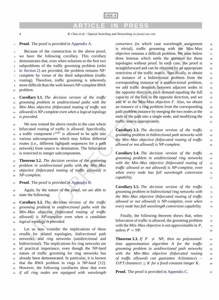
Fig. 5. Uniform pattern,N = 16, W = 128,C = 12, L = 80%.
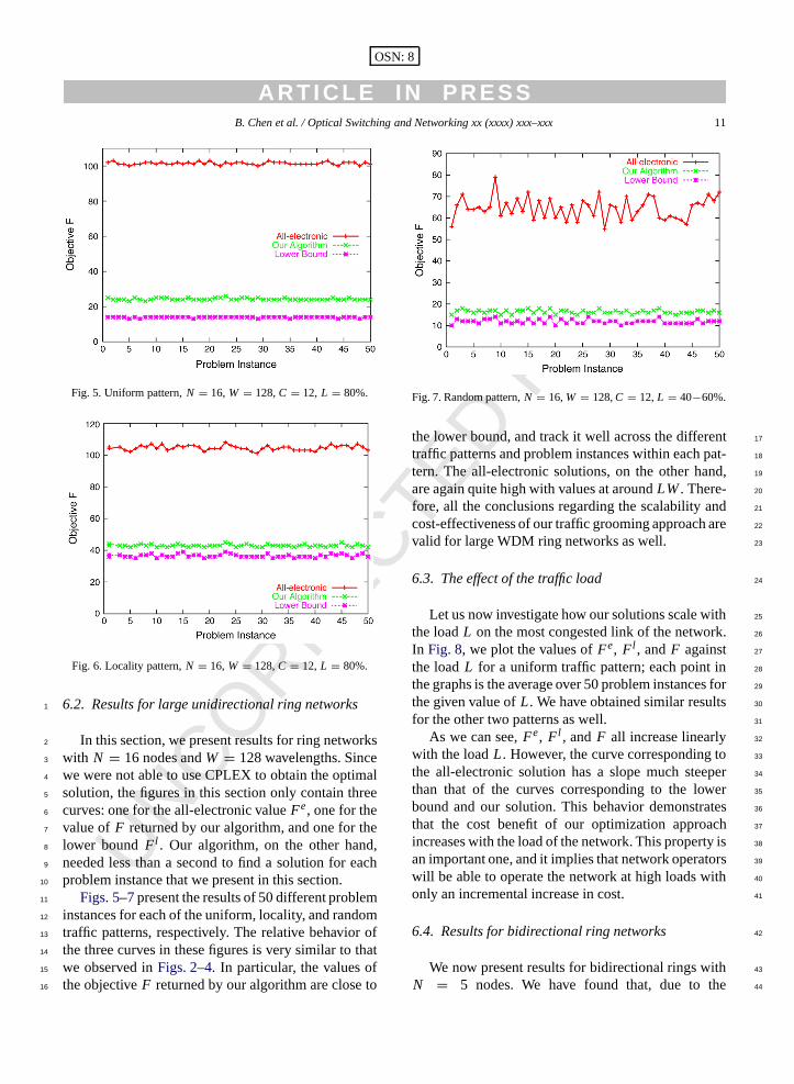
Fig. 6. Locality pattern,N = 16, W = 128,C = 12, L = 80%.
6.2. Results for large unidirectional ring networks1
In this section, we present results for ring networks2
with N = 16 nodes andW = 128 wavelengths. Since3
we were not able touse CPLEX to obtain the optimal4
solution, the figures in this section only contain three5
curves: one for the all-electronic valueFe, one for the6
value ofF returned by our algorithm, and one for the7
lower bound Fl . Our algorithm, on the other hand,8
needed less than a secondto find a solution for each9
problem instance that we present in this section.10
Figs. 5–7present the results of 50 different problem11
instances for each of the uniform, locality, and random12
traffic patterns, respectively. The relative behavior of13
the three curves in these figures is very similar to that14
we observed inFigs. 2–4. In particular, the values of15
theobjectiveF returned by our algorithm are close to16
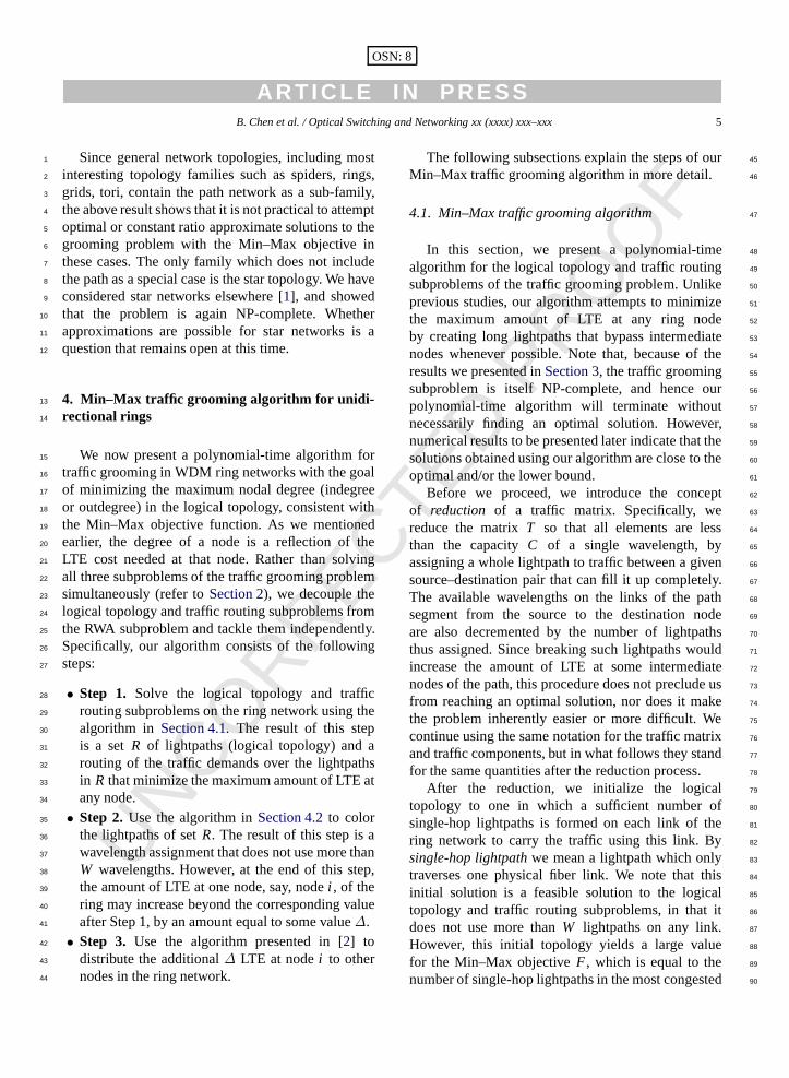
Fig. 7. Random pattern,N = 16,W = 128,C = 12,L = 40−60%.
the lower bound, and track it well across the different 17
traffic patterns and problem instances within each pat-18
tern. The all-electronic solutions, on the other hand, 19
are again quite high with values at aroundLW. There- 20
fore, all the conclusions regarding the scalability and 21
cost-effectiveness of our traffic grooming approach are22
valid for large WDM ring networks as well. 23
6.3. The effect of the traffic load 24
Let us now investigate how our solutions scale with 25
the loadL on the most congested link of the network. 26
In Fig. 8, we plot thevalues ofFe, Fl , andF against 27
the loadL for a uniform traffic pattern; each point in 28
the graphs is the average over 50 problem instances for 29
the given value ofL. We haveobtained similar results 30
for the other two patterns as well. 31
As we can see,Fe, Fl , andF all increase linearly 32
with the loadL. However, the curve corresponding to 33
the all-electronic solution has a slope much steeper 34
than that of the curves corresponding to the lower 35
bound and our solution. This behavior demonstrates36
that the cost benefit of our optimization approach 37
increases with the load of thenetwork. This property is 38
an important one, and it implies that network operators39
will be able to operate the network at high loads with 40
only an incremental increase in cost. 41
6.4. Results for bidirectional ring networks 42
We now present results for bidirectional rings with 43
N = 5 nodes. We have found that, due to the 44

UNCORRECTE
D PRO
OF
A R T I C L E I N P R E S S12 B. Chen et al. / Optical Switching and Networking xx (xxxx) xxx–xxx
OSN: 8
Fig. 8. Uniform pattern,N = 16, W = 128,C = 12, various loads.
fact that the ILP formulation for bidirectional rings1
contains far more variables and constraints than in2
the unidirectional case, for rings with more than five3
nodes, CPLEX takes too long (several days) to find an4
optimal solution for rings with more than five nodes.5
We alsonote that, since the routing of traffic is part6
of the problem, it is not possible to a priori determine7
the loading of each link from the traffic matrix as in8
the unidirectional case. Therefore, we use the concept9
of grooming effectivenessto characterize the results.10
The grooming effectiveness is defined as the ratio of11
the maximum nodal degree of a solution to the one12
required by an all-electronic solution with shortest13
path routing. By definition, the smaller the grooming14
effectiveness, the better the solution in terms of the15
Min–Max objective.16
For each experiment, we again generate 5017
different problem instances, and we compare the18
traffic grooming effectiveness values for the following19
four values:20
• Theoptimalsolution returned by CPLEX.21
• The decompose optimalsolution. In this case, we22
use the shortest-path decomposition we described23
in Section 5and we solve the two unidirectional24
ring instances independently using CPLEX on25
the corresponding unidirectional ILPs. We then26
combine the two solutions, and compute the overall27
Min–Max result (and corresponding grooming28
effectiveness value).29
• The decompose heuristicsolution. This is similar30
to the decompose optimal method, except that we31
use the unidirectional heuristic inFig. 1 instead32
Fig. 9. Bidirectional uniform, N = 5, W = 64, C = 12, Fe =33–37.
Fig. 10. Bidirectional locality,N = 5, W = 64, C = 12, Fe =78–94.
of CPLEX to solve each unidirectional ring 33
instance. 34
• The bidirectional algorithm solution, which is 35
obtained by running the algorithm we presented 36
in Section 5. Recall that this algorithm focuses on 37
the overall objective for the bidirectional ring as 38
a whole, and is such that the solution to each 39
unidirectional ring instance takes into account the 40
solution to the other. 41
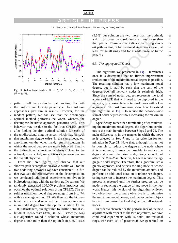
Figs. 9–11 present the grooming effectiveness 42
values of 50 instances for each of the uniform, 43
locality, and random traffic patterns, respectively. It 44
is not surprising to see that, overall, the grooming 45
effectiveness is best for the locality pattern, since the46
UNCORRECTE
D PRO
OF
A R T I C L E I N P R E S SB. Chen et al. / Optical Switching and Networking xx (xxxx) xxx–xxx 13
OSN: 8
Fig. 11. Bidirectional random,N = 5, W = 64, C = 12,Fe = 31–78.
pattern itself favors shortest path routing. For both1
the uniform and locality patterns, all four solution2
approaches give similar results. However, for the3
random pattern, we can see that the decompose4
optimal method performs the worst, whereas the5
decompose heuristic approach performs well. This6
behavior may be due to the fact that CPLEX stops7
after finding the first optimal solution for each of8
the unidirectional ring instances, which may be such9
that maximum degree exists in the same node; our10
algorithm, on the other hand, returns solutions in11
which the nodal degrees are more balanced. Finally,12
the bidirectional algorithm is always close to the13
optimal, as expected, since ittakes into consideration14
the overall objective.15
From the three figures, we observe that our16
shortest-path decomposition always works well for the17
five-node ring networks we have considered. To fur-18
ther evaluate the effectiveness of the decomposition,19
we conducted additional experiments on five-node20
bidirectional rings with the random traffic pattern. We21
randomly generated 100,000 problem instances and22
obtained the optimal solutions using CPLEX. The re-23
sulting maximum nodal degrees range from 9 to 74,24
with an average around 33. We then run the bidirec-25
tional heuristic and recorded the difference in maxi-26
mum nodal degree from the optimal solution. Of the27
100,000 instances, our algorithm found the optimal so-28
lution in 38,895 cases (39%); in 55,519 cases (55.5%)29
our algorithm found a solution whose maximum30
degree is one more than the optimal; in 5,550 cases31
(5.5%) our solution are two more than the optimal; 32
and in 36 cases, our solution are three more than33
the optimal. These resultsindicate that using short- 34
est path routing in bidirectional rings works well, at 35
least for small rings and for a wide range of traffic 36
patterns. 37
6.5. The aggregate LTE cost 38
The algorithm we presented inFig. 1 terminates 39
once it is determined that no further improvement 40
(reduction) of the maximum nodal degree is possible.41
The resulting solution has a low maximum nodal 42
degree, but it may be such that the sum of the43
degrees over all network nodes is relatively high. 44
Since the sum of nodal degrees represents the total45
amount of LTE that will need to be deployed in the 46
network, it is desirable to obtain solutions with a low 47
aggregate LTE cost. We now show how to extend 48
the algorithm inFig. 1 to reduce the network-wide 49
sum of nodal degrees without increasing the maximum 50
degree. 51
Specifically, rather than terminating after minimiz- 52
ing the maximum nodal degree, the algorithm contin- 53
ues to the main iteration between Steps 6 and 21. The54
main difference is in the manner in which the node 55
m is selected in Step 7 and in the criterion for ter- 56
mination in Step 21. Note that, although it may not 57
be possible to reduce the degree at the node where58
it is maximum, it may be possible to reduce the 59
degree at some other ring node; doing so will not 60
affect the Min–Max objective, but will reduce the ag- 61
gregate nodal degree. Therefore, the algorithm uses a62
greedy approach, and selects the ring nodem whose 63
degree can be reduced by the maximum amount, and64
performs an additional iteration to reducem’s degree, 65
taking carenot to increase the maximum degree. This 66
process is repeated until no further progress can be67
made in reducing the degree of any node in the net-68
work. Hence, this version of the algorithm achieves 69
two objectives: theprimary objective is to minimize 70
the maximum nodal degree, and the secondary objec-71
tive is to minimize the total degree over all network 72
nodes. 73
In order to characterize the performance of the new74
algorithm with respect to the two objectives, we have 75
conducted experiments with 16-node unidirectional 76
rings. For each set of parameters we generated 5077

UNCORRECTE
D PRO
OF
A R T I C L E I N P R E S S14 B. Chen et al. / Optical Switching and Networking xx (xxxx) xxx–xxx
OSN: 8
Fig. 12. Uniform,N = 16,W = 128,C = 12,L = 80%, maximumdegree.
Fig. 13. Random,N = 16,W = 128,C = 12,L = 80%, maximumdegree.
problem instances, and we recorded the maximum1
nodal degree and the total degree over all network2
nodes for two algorithms: the algorithm inFig. 1after3
making the modifications we described above, and4
the algorithm by Zhang and Qiao [13]. The latter5
algorithm was developed specifically for minimizing6
the total number of SONET ADMs (i.e., the total7
degree) in the network. For each problem instance, we8
also computed the lower bound on the maximum and9
total degrees.10
Figs. 12and 13 plot the maximum nodal degree11
of each problem instance for the uniform and12
random traffic patterns, respectively; the results for the13
locality pattern are similar to those for the random14
Fig. 14. Uniform,N = 16, W = 128, C = 12, L = 80%, totaldegree.
Fig. 15. Random,N = 16, W = 128, C = 12, L = 80%, totaldegree.
pattern and are omitted. Our algorithm outperforms 15
Zhang and Qiao’s algorithm for the random (and 16
locality) patterns, while the results for the uniform 17
pattern are mixed, with eachalgorithm performing 18
better than the other over some of the problem19
instances. Interestingly, the relative behavior of the 20
two algorithms is similar in terms of the total degree 21
(over all network nodes), as shown inFigs. 14and15. 22
Again, our algorithm outperforms Zhang and Qiao’s 23
algorithm for the random (andlocality) patterns, while 24
the latter performs better for the uniform pattern. 25
The fact that Zhang and Qiao’s algorithm performs 26
well for uniform traffic is due to the nature of the 27
algorithm which attempts to form full circles of 28

UNCORRECTE
D PRO
OF
A R T I C L E I N P R E S SB. Chen et al. / Optical Switching and Networking xx (xxxx) xxx–xxx 15
OSN: 8
Fig. 16. Example of path construction for the proof ofTheorem 3.1, N = 2n+ 3, W = 3.
unit traffic components which are then groomed into1
wavelengths; this operation is most successful when2
demands are symmetric. However, for the asymmetric3
traffic scenarios that are more likely to be encountered4
in practice, our algorithm performs better, not only in5
terms of the maximum nodal degree, but also in terms6
of the total degree over all network nodes.7
Overall, the results we presented in this section8
demonstrate that our Min–Max optimization approach9
for traffic grooming is successful in obtaining10
solutions that keep the maximum nodal degree11
low. Moreover, our solutions also tend to keep the12
overall network cost (in terms of the total degree13
over all network nodes) low, and compare favorably14
to solutions obtained by algorithms whose main15
objective is network-wide cost minimization.16
7. Concluding remarks17
We have studied a new variant of the traffic18
grooming problem in ring networks, where the19
objective is to minimize the maximum LTE cost at20
any node. We have developed new algorithms for21
traffic grooming and wavelength assignment in ring22
networks. We have demonstrated that our algorithms23
perform well for a wide range of traffic patterns and24
system parameter values, not only in terms of the25
maximum LTE cost, but alsoin terms of the total LTE26
cost over all network nodes.27
Appendix A. Proof of Theorem 3.128
The reduction is from the Subset Sum problem [8].29
An instance of the SubsetSum problem consists of30
n elements of sizewi ∈ Z+,∀i ∈ {1, 2, . . . , n},31
and a goalB. The question is whether there exists32
a subset of elements whose sizes totalB. Let B1 =33
max{B,∑
i wi − B}. Construct a path network using34
the following transformation:N = 2n + 3, W = 3,35
C = ∑i wi + 1, and let the objective beF = 2. The36
2n+ 3 nodes of the path are labeledS, 1, 2, . . . , 2n+37
1, D, and the traffic matrix is 38
t(sd) =
C + 1, s ∈ {1, 2, . . . , n− 1}∪{n+ 2, n+ 3, . . . , 2n},d = s+ 1;
B1+ 1, s= n, d = n+ 1; ors= n+ 1, d = n+ 2;
C − B1, s= n, d = n+ 2;ws, s ∈ {1, 2, . . . , n},
d = s+ (n+ 1);C, s= S, d = n+ 1; or s= n+ 1,
d = D;C, s= S, d = 1; or s= 2n+ 1,
d = D0, otherwise. 39
The traffic matrix is set up so that we are forced to 40
use the virtual topology shown inFig. 16. Specifically, 41
the first of the three wavelengths is used to form two 42
lightpaths, one from nodeS to noden + 1, and one 43
from noden + 1 to node D; both these lightpaths 44
are filled to capacity carrying the corresponding 45
traffic demands of magnitudeC. Therefore, this first 46
wavelength cannot be used to carry any other traffic. 47
The second wavelength is used to form single-hop48
lightpaths between adjacent pairs of nodes in the path; 49
these lightpaths are denoted by the straight arrows 50
in Fig. 16. However,note that the traffic demands in 51
the top row of the traffic matrix above are greater 52
than the capacityC of a wavelength. Therefore, the 53
third wavelength is used to form single-hop lightpaths 54
between nodes(i , i + 1), i = 1, . . . , n − 1, n + 55
2, . . . , 2n, in the path. The single-hop lightpaths on 56
this third wavelength between any such pair(i , i + 57
1) of nodes carry the following traffic components: 58
(1) the one unit of traffic from nodei to nodei + 1 59
(the otherC units of such traffic are carried by the 60
single-hop lightpath on the second wavelength), and61
(2) thew j units of traffic from nodej , j = 1, . . . , i , 62
to node j+n+1. SinceC =∑i wi+1, the single-hop 63
lightpath on the third wavelength from nodei to i + 1 64
has enough capacity to carry this traffic, for all suchi . 65
Finally, the third wavelength is also used to form a 66

UNCORRECTE
D PRO
OF
A R T I C L E I N P R E S S16 B. Chen et al. / Optical Switching and Networking xx (xxxx) xxx–xxx
OSN: 8
Fig. 17. Example of path construction for the proof ofTheorem 3.2: (a) the original MCF instance, and (b) the corresponding path network.
direct lightpath from noden to noden+2 that bypasses1
noden + 1, and the result is the virtual topology in2
Fig. 16. Note that no more lightpaths can be added to3
this virtual topology, and no existing lightpaths can be4
split without violating the objectiveF .5
After grooming all the traffic except forwi , which6
have to go through noden+1 with or without stopping,7
the capacity left in the lightpath from noden to node8
n + 2 is equal to B1, and the capacities left in the9
lightpaths from noden to noden + 1 and from node10
n + 1 to noden + 2 areboth equal to∑
i wi − B1.11
Since bifurcation isnot allowed, it is possible to use12
the virtual topology above to groom the traffic,if and13
only if there is asubset of{t(i,i+n+1)} whose sum14
is exactlyB1. Since deciding the satisfiability of the15
Subset Sum problem is NP-complete, then the new16
grooming problem is also NP-complete.�17
Appendix B. Proof of Theorem 3.218
The reduction is from the constrained multicom-19
modity flow (MCF) problem inthree-stage networks20
with three nodes in the second stage, which is NP-21
complete [7]. An instance of the constrained MCF22
problem hasN1, N2, andN3 as the sets of nodes form-23
ing the three stages, with|N1 ∪ N2 ∪ N3| = n, and24
|N2| = 3 (refer toFig. 17(a)). E ⊂ (N1×N2)∪ (N2×25
N3) is the set of edges in the network, each of unit26
capacity, andQ ⊂ (N1 × N3) is the set of traffic de-27
mands, each also of unit magnitude. The problem is 28
whether a feasible flow assignment satisfying the flow 29
constraints exists. 30
To transform an instance of the MCF problem to an 31
instance of the path grooming problem, we construct 32
a path network with N = 3 × n nodes, labeled 33
−n, . . . ,−1, 1, . . . , n, n+ 1, . . . , 2n (seeFig. 17(b)). 34
Let I j and Oj denote the indegree and outdegree, 35
respectively, of nodej of the three-stage network; 36
for exampleI6 = 1 and O6 = 0 for the network 37
of Fig. 17(a). Our decision goal is set toF = 38
maxj {I j , Oj }; for the instance of Fig. 17, F = 2. 39
We let the wavelength capacity beC = 2, and we 40
do not impose any constraint on the numberW of 41
wavelengths; in other words,W can be as large as 42
needed (for practical purposes, we can letW = K N2, 43
whereK is an appropriate constant, so that the number 44
of wavelengths is sufficient for setting up direct 45
lightpaths between any pair of nodes in the path). The46
traffic matrixt(sd) for the path grooming instance is 47
t(sd) =
1, (s, d) ∈ E ∪ Q;C × (F − Id), ∀d = 1, 2, . . . , n,
s= d − (n+ 1);C × (F − Os), ∀s= 1, 2, . . . , n,
d = s+ n. 48
Because of the demands of sizeC(=2), a direct 49
lightpath needs to be formed for each such demand in50
order not to exceed the goalF ; the resulting logical 51

UNCORRECTE
D PRO
OF
A R T I C L E I N P R E S SB. Chen et al. / Optical Switching and Networking xx (xxxx) xxx–xxx 17
OSN: 8
Fig. 18. The logical topology for the proof ofTheorem 3.2: (a) the topology after forming lightpaths for each demand of sizeC, and (b) thetopology after forming additional lightpaths for each demand between node pairs in setE.
topology for the example ofFig. 17(a) is shown in1
Fig. 18(a). Recall thatI6 = 1 andO6 = 0 in thethree-2
stage network ofFig. 17. Therefore, the above traffic3
matrix specifiest(−4,6) = C = 2 andt(6,15) = 2C =4
4. There is one lightpath from node 4 to node 6, and5
this lightpath carries the total demandt(−4,6), while6
there are two lightpaths from node 6 to node 15, each7
of them carryingC units ofthe demandt(6,15).8
The only way to satisfy the unit demands between9
node pairs in setE in the above traffic matrix, is10
to form a direct lightpath for each such demand.11
The resulting topology is shown inFig. 18(b). For12
example, consider the source–destination pair(1, 3) ∈13
E (refer to Fig. 17(a)). A direct lightpath has been14
formed between nodes 1 and 3 inFig. 18(b); similarly15
for other node pairs in setE.16
The logical topology inFig. 18(b) is such that17
exactly two lightpaths originate from, and terminate18
at, each nodei = 1, 2, . . . , n, of thepath. Hence, it is19
not possible to add any new lightpath with such a node20
as the origin or termination point without violating21
the goal F = 2. Consequently, we have to use the22
remaining capacities left on the lightpaths formed23
between node pairs in setE in order to carry the24
demands in the above traffic matrix due to node pairs25
in set Q. This can be doneif and only if the original26
constrained MCF problem has a solution. Since MCF27
is NP-complete, so is our problem. �28
Appendix C. Proof of Theorem 3.329
The reduction is from the same MCF problem30
used above. For a given MCF problem instance, let31
P denote the corresponding instance of the path32
problem constructed in the proof ofTheorem 3.2, 33
and let F denote the corresponding objective,F = 34
maxj {I j , Oj }. For this proof, we construct a path 35
instanceP′ and objectiveF ′ by modifying the instance 36
P and objectiveF of the previous proof as follows. 37
Case (a). If F exists in N2, then we create K 38
replicas of each node inN1 andN3, and connect them 39
to N2 in exactly the same way as the original nodes 40
do. LetN11 , . . . , NK
1 denote theK replicas of node-set 41
N1, and, similarly,N13 , . . . , NK
3 denote the replicas of 42
node-setN3. If a nodem in N1 is connected to each 43
node of a subsetN′2 of the node-setN2, we make 44
the corresponding nodesm1, . . . , mK connect to the 45
same nodesN′2. We do the same for the new sets 46
N13 , . . . , NK
3 . We also replicate thedemands between 47
N2 and other nodes accordingly. Also, if there is 48
demand from nodes ∈ N1 to node d ∈ N3, we 49
add equal demands from each nodesi ∈ Ni1 to each 50
nodedi ∈ Ni3, i = 1, . . . , K . At the end of these 51
steps, we haveK + 1 copies of the original MCF 52
problem, an we set the new goalF ′ = (K + 1)F . 53
We alsokeepC = 2, and we use the same procedure 54
as in the previous proof to transform the MCF instance55
to aunidirectional path problem instance, which now 56
has N = 3 × (K |N1 + N3| + |N2|) nodes. Using 57
this polynomial-time transformation, we obtain a new 58
traffic grooming problemP′. 59
Now suppose there exists a polynomial-time 60
algorithmA that can guaranteeA(P′)− O PT(P′) ≤ 61
K . We solveP′ using this algorithm. From the result, 62
we can easily decide ifO PT(P) ≤ F , because of the 63
following observations: 64

UNCORRECTE
D PRO
OF
A R T I C L E I N P R E S S18 B. Chen et al. / Optical Switching and Networking xx (xxxx) xxx–xxx
OSN: 8
(1) O PT(P′) = (K + 1)O PT(P), so O PT(P′)1
must be an integer multiple ofK + 1.2
(2) A(P′) − O PT(P′) ≤ K ; hence O PT(P′) = Y,3
whereY is the largest multiple ofk + 1 less than4
A(P′).5
(3) SinceO PT(P) = O PT(P′)/(K + 1), we can6
immediately compute O PT(P) and decide if7
O PT(P) ≤ F .8
For any instance of MCF, we can construct an9
instanceP′ in polynomial time, use the method above10
to decide ifO PT(P) ≤ F in polynomial time, then11
further decide if MCF has a solution, i.e., solve MCF12
in polynomial time. This is only possible ifP = NP.13
Case (b). If F exists in N1 or N3, we makeK14
replicas of the node-setN2, that is, we add node-sets15
N12 , . . . , NK
2 , each with three nodes. We also replicate16
the traffic demands accordingly, and set the objective17
F ′ = (K + 1)F . By proceeding as in Case (a), we18
obtain the same result.19
Case (c). If F exists in bothN2 and in N1 or N3,20
use either Case (a) or Case (b) for the proof.�21
References22
[1] B. Chen, R. Dutta, G.N. Rouskas, Traffic grooming in star23
networks, in: Proceedings of the First Traffic Grooming24
Workshop, October 2004.
[2] L.-W. Chen, E. Modiano, Efficient routing and wavelength as- 25
signment for reconfigurable WDM networks with wavelength 26
converters, in: Proceedings of IEEE INFOCOM, 2003. 27
[3] T. Cinkler, Traffic andλ grooming, IEEE Network 17 (2) 28
(2003) 16–21. 29
[4] R. Dutta, G.N. Rouskas, A survey of virtual topology design 30
algorithms for wavelength routed optical networks, Optical 31
Networks 1 (1) (2000) 73–89. 32
[5] R. Dutta, G.N. Rouskas, On optimal traffic grooming in WDM 33
rings, IEEE Journal on Selected Areas in Communications 2034
(1) (2002) 110–121. 35
[6] R. Dutta, G.N. Rouskas, Traffic grooming in WDM networks: 36
Pastand future, IEEE Network 16 (6) (2002) 46–56. 37
[7] E.S. Elmallah, J.C. Culberson, Multicommodity flows in 38
simple multistage networks, Networks 25 (1995) 19–30. 39
[8] M.R. Garey, D.S. Johnson, Computers and Intractability, 40
W. H. Freeman and Co., New York, 1979. 41
[9] U. Gupta, D. Lee, J. Leung, Efficient algorithms for interval 42
graphs and circular-arc graphs, Networks 12 (1982) 459–467.43
[10] E. Modiano, P.J. Lin, Traffic grooming in WDM networks, 44
IEEE Communications 39 (7) (2001) 124–129. 45
[11] A. Tucker, Coloring a family of circular-arc graphs, SIAM 46
Journal of Applied Mathematics 29 (1975) 493–502. 47
[12] G. Wilfong, P. Winkler, Ring routing and wavelength 48
translation, in: Proceedings of the 9th Annual ACM-SIAM 49
Symposium on Discrete Algorithms, 1998, pp. 333–341. 50
[13] X. Zhang, C. Qiao, An effective and comprehensive 51
approach to traffic grooming and wavelength assignment in 52
SONET/WDM rings, IEEE/ACM Transactions on Networking 53
8 (5) (2000) 608–617. 54
[14] K. Zhu, B. Mukherjee, A review of traffic grooming in 55
WDM optical networks: Architectures and challenges, Optical 56
Networks 4 (2) (2003) 55–64. 57


![Optical Amplifiers Placement in WDM Mesh Networks for ...kamal/Docs/hk09.pdf · Networks for Optical Multicasting Service Support ... for AOM traffic. The network cost in [1] ...](https://static.fdocuments.in/doc/165x107/5aa4b3237f8b9ab4788c3426/optical-ampliers-placement-in-wdm-mesh-networks-for-kamaldocshk09pdfnetworks.jpg)