Tractor Sensor Module Installation Instructions - … · ule detects itself being connected to a...
14
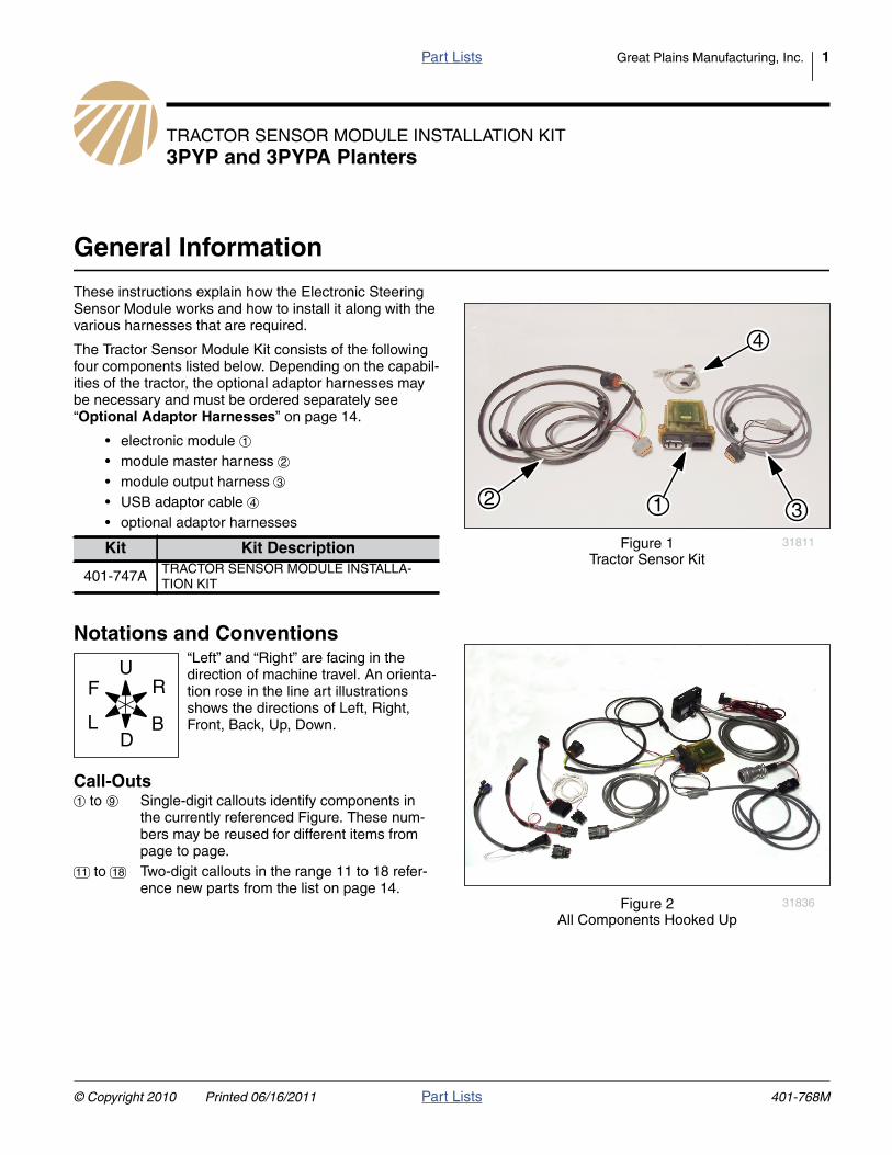
P ar t Lists Great Plains Manufacturing, Inc. 1 © Copyright 2010 Printed 06/16/2011 P ar t Lists 401-768M TRACTOR SENSOR MODULE INSTALLATION KIT 3PYP and 3PYPA Planters General Information These instructions explain how the Electronic Steering Sensor Module works and how to install it along with the various harnesses that are required. The Tractor Sensor Module Kit consists of the following four components listed below. Depending on the capabil- ities of the tractor, the optional adaptor harnesses may be necessary and must be ordered separately see “Optional Adaptor Harnesses” on page 14. • electronic module • module master harness • module output harness • USB adaptor cable • optional adaptor harnesses Notations and Conventions Call-Outs Null4: Kit Kit Description 401-747A TRACTOR SENSOR MODULE INSTALLA- TION KIT Nu l l 4 : “Left” and “Right” are facing in the direction of machine travel. An orienta- tion rose in the line art illustrations shows the directions of Left, Right, Front, Back, Up, Down. to Single-digit callouts identify components in the currently referenced Figure. These num- bers may be reused for different items from page to page. to Two-digit callouts in the range 11 to 18 refer- ence new parts from the list on page 14. Null4: Figure 1 Tractor Sensor Kit 31811 1 3 2 4 1 2 3 4 Null4: Figure 2 All Components Hooked Up 31836 U D L R B F 1 9 11 18
Transcript of Tractor Sensor Module Installation Instructions - … · ule detects itself being connected to a...
Part Lists Great Plains Manufacturing, Inc. 1
TRACTOR SENSOR MODULE INSTALLATION KIT3PYP and 3PYPA Planters
General Information
These instructions explain how the Electronic SteeringSensor Module works and how to install it along with thevarious harnesses that are required.
The Tractor Sensor Module Kit consists of the followingfour components listed below. Depending on the capabil-ities of the tractor, the optional adaptor harnesses maybe necessary and must be ordered separately see“Optional Adaptor Harnesses” on page 14.
• electronic module• module master harness• module output harness• USB adaptor cable• optional adaptor harnesses
Notations and Conventions
Call-Outs
Null4:
Kit Kit Description
401-747A TRACTOR SENSOR MODULE INSTALLA-TION KIT
Null4:“Left” and “Right” are facing in thedirection of machine travel. An orienta-tion rose in the line art illustrationsshows the directions of Left, Right,Front, Back, Up, Down.
to Single-digit callouts identify components inthe currently referenced Figure. These num-bers may be reused for different items frompage to page.
to Two-digit callouts in the range 11 to 18 refer-ence new parts from the list on page 14.
Null4:
Figure 1Tractor Sensor Kit
31811
1 32
4
1
2
3
4
Null4:
Figure 2All Components Hooked Up
31836
U
DL
R
B
F
1 9
11 18
© Copyright 2010 Printed 06/16/2011 Part Lists 401-768M
2 Great Plains Manufacturing, Inc. Front Page Part Lists Tractor Sensor Module Installation
Descriptions of Module Components
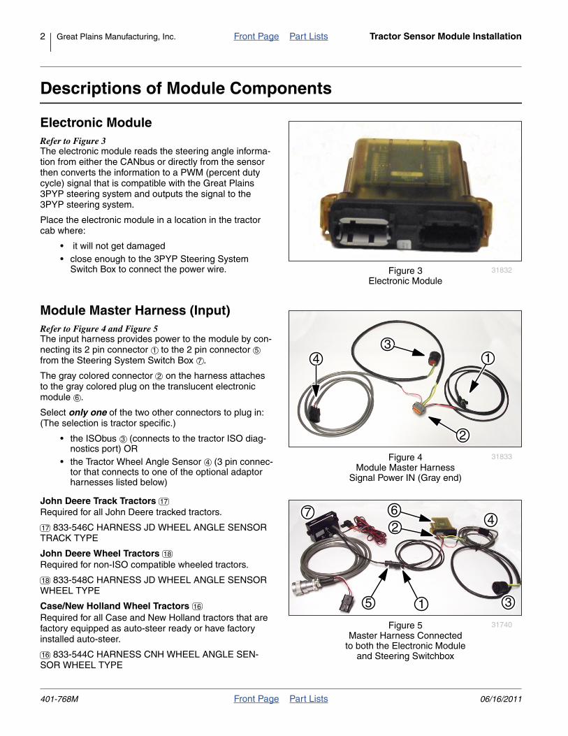
Electronic ModuleRefer to Figure 3The electronic module reads the steering angle informa-tion from either the CANbus or directly from the sensorthen converts the information to a PWM (percent dutycycle) signal that is compatible with the Great Plains3PYP steering system and outputs the signal to the3PYP steering system.
Place the electronic module in a location in the tractorcab where:
• it will not get damaged• close enough to the 3PYP Steering System
Switch Box to connect the power wire.
Module Master Harness (Input)Refer to Figure 4 and Figure 5The input harness provides power to the module by con-necting its 2 pin connector to the 2 pin connectorfrom the Steering System Switch Box .
The gray colored connector on the harness attachesto the gray colored plug on the translucent electronicmodule .
Select only one of the two other connectors to plug in:(The selection is tractor specific.)
• the ISObus (connects to the tractor ISO diag-nostics port) OR
• the Tractor Wheel Angle Sensor (3 pin connec-tor that connects to one of the optional adaptorharnesses listed below)
Null4:
John Deere Track TractorsRequired for all John Deere tracked tractors.
833-546C HARNESS JD WHEEL ANGLE SENSORTRACK TYPE
John Deere Wheel TractorsRequired for non-ISO compatible wheeled tractors.
833-548C HARNESS JD WHEEL ANGLE SENSORWHEEL TYPE
Case/New Holland Wheel TractorsRequired for all Case and New Holland tractors that arefactory equipped as auto-steer ready or have factoryinstalled auto-steer.
833-544C HARNESS CNH WHEEL ANGLE SEN-SOR WHEEL TYPE
Null4:
Figure 3Electronic Module
31832
Null4:
Figure 4Module Master Harness
Signal Power IN (Gray end)
31833
31
2
41 5
7
2
6
3
4
Null4:
Figure 5Master Harness Connected
to both the Electronic Moduleand Steering Switchbox
31740
5
6
1
4
3
72
17
17
18
18
16
16
401-768M Front Page Part Lists 06/16/2011
Descriptions of Module Components Front Page Part Lists Great Plains Manufacturing, Inc. 3
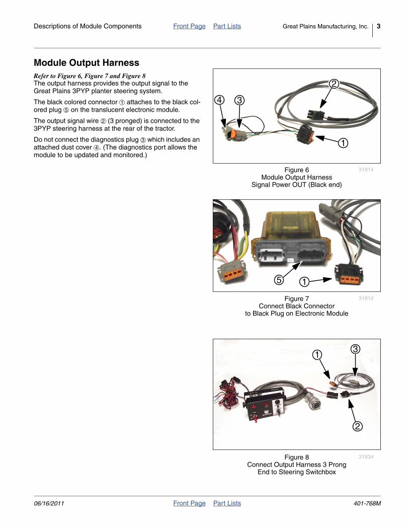
Module Output HarnessRefer to Figure 6, Figure 7 and Figure 8The output harness provides the output signal to theGreat Plains 3PYP planter steering system.
The black colored connector attaches to the black col-ored plug on the translucent electronic module.
The output signal wire (3 pronged) is connected to the3PYP steering harness at the rear of the tractor.
Do not connect the diagnostics plug which includes anattached dust cover . (The diagnostics port allows themodule to be updated and monitored.)
Null4:
Figure 6Module Output Harness
Signal Power OUT (Black end)
31814
2
34
1
1
5
2
3
4
Null4:
Figure 7Connect Black Connector
to Black Plug on Electronic Module
31812
15
Null4:
Figure 8Connect Output Harness 3 Prong
End to Steering Switchbox
31834
2
13
06/16/2011 Front Page Part Lists 401-768M
4 Great Plains Manufacturing, Inc. Front Page Part Lists Tractor Sensor Module Installation
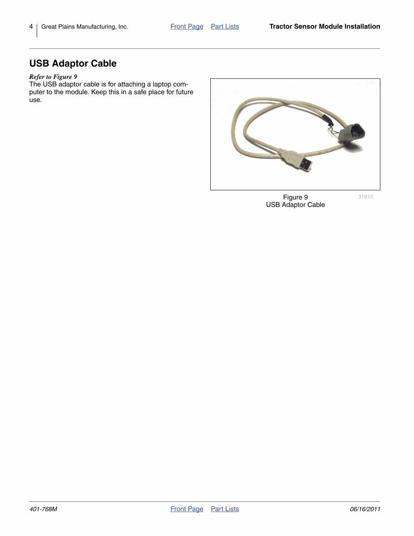
USB Adaptor CableRefer to Figure 9The USB adaptor cable is for attaching a laptop com-puter to the module. Keep this in a safe place for futureuse.
Null4:
Figure 9USB Adaptor Cable
31815
401-768M Front Page Part Lists 06/16/2011
Descriptions of Module Components Front Page Part Lists Great Plains Manufacturing, Inc. 5
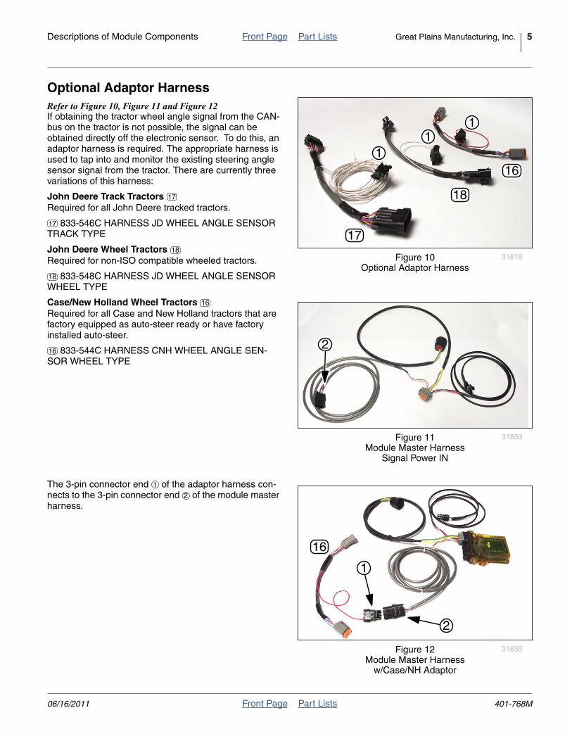
Optional Adaptor HarnessRefer to Figure 10, Figure 11 and Figure 12If obtaining the tractor wheel angle signal from the CAN-bus on the tractor is not possible, the signal can beobtained directly off the electronic sensor. To do this, anadaptor harness is required. The appropriate harness isused to tap into and monitor the existing steering anglesensor signal from the tractor. There are currently threevariations of this harness:
John Deere Track TractorsRequired for all John Deere tracked tractors.
833-546C HARNESS JD WHEEL ANGLE SENSORTRACK TYPE
John Deere Wheel TractorsRequired for non-ISO compatible wheeled tractors.
833-548C HARNESS JD WHEEL ANGLE SENSORWHEEL TYPE
Case/New Holland Wheel TractorsRequired for all Case and New Holland tractors that arefactory equipped as auto-steer ready or have factoryinstalled auto-steer.
833-544C HARNESS CNH WHEEL ANGLE SEN-SOR WHEEL TYPE
The 3-pin connector end of the adaptor harness con-nects to the 3-pin connector end of the module masterharness.
Null4:
Figure 10Optional Adaptor Harness
31816
17
18
161
11
17
17
18
18
Null4:
Figure 11Module Master Harness
Signal Power IN
31833
2
16
16
Null4:
Figure 12Module Master Harness
w/Case/NH Adaptor
31839
16
2
1
1
2
06/16/2011 Front Page Part Lists 401-768M
6 Great Plains Manufacturing, Inc. Front Page Part Lists Tractor Sensor Module Installation
Description of the Steering Sensor Module
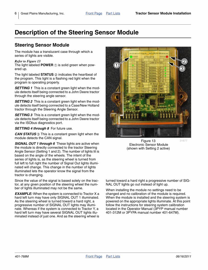
Steering Sensor ModuleThe module has a translucent case through which aseries of lights are visible.
Refer to Figure 13The light labeled POWER is solid green when pow-ered up.
The light labeled STATUS indicates the heartbeat ofthe program. This light is a flashing red light when theprogram is operating properly.
SETTING 1 This is a constant green light when the mod-ule detects itself being connected to a John Deere tractorthrough the steering angle sensor.
SETTING 2 This is a constant green light when the mod-ule detects itself being connected to a Case/New Hollandtractor through the Steering Angle Sensor.
SETTING 3 This is a constant green light when the mod-ule detects itself being connected to a John Deere tractorvia the ISObus diagnostics port.
SETTING 4 through 8 For future use.
CAN STATUS This is a constant green light when themodule detects the CAN signal.
SIGNAL OUT 1 through 6 These lights are active whenthe module is directly connected to the tractor SteeringAngle Sensor (Setting 1 and 2). The number of lights lit isbased on the angle of the wheels. The intent of theseries of lights is, as the steering wheel is turned fromfull left to full right the number of Signal Out lights illumi-nated will change. This change in the number of lightsilluminated lets the operator know the signal from thetractor is changing.
Since the value of the signal is based solely on the trac-tor, at any given position of the steering wheel the num-ber of lights illuminated may not be the same.
EXAMPLE: When the system is connected to Tractor X ahard left turn may have only SIGNAL OUT 1 illuminated.As the steering wheel is turned toward a hard right, aprogressive number of SIGNAL OUT lights may illumi-nate. Whereas if the system is connected to Tractor Y, ahard left turn may have several SIGNAL OUT lights illu-minated instead of just one. And as the steering wheel is
turned toward a hard right a progressive number of SIG-NAL OUT lights go out instead of light up.
When installing the module no settings need to bechanged and no calibration of the module is required.When the module is installed and the steering system ispowered on the appropriate lights illuminate. At this pointfollow the instructions for steering system calibrationlocated in the Operator Manual (3PYP manual number401-312M or 3PYPA manual number 401-647M).
Null4:
Figure 13 Electronic Sensor Module
(shown with Setting 2 active)
31877
21
31
2
3
401-768M Front Page Part Lists 06/16/2011
Installation Front Page Part Lists Great Plains Manufacturing, Inc. 7
Installation
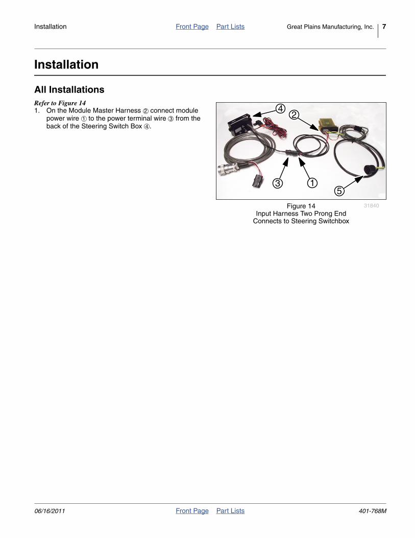
All InstallationsRefer to Figure 141. On the Module Master Harness connect module
power wire to the power terminal wire from theback of the Steering Switch Box .
Null4:
Figure 14Input Harness Two Prong End
Connects to Steering Switchbox
31840
1
4
35
22
1 3
4
06/16/2011 Front Page Part Lists 401-768M
8 Great Plains Manufacturing, Inc. Front Page Part Lists Tractor Sensor Module Installation
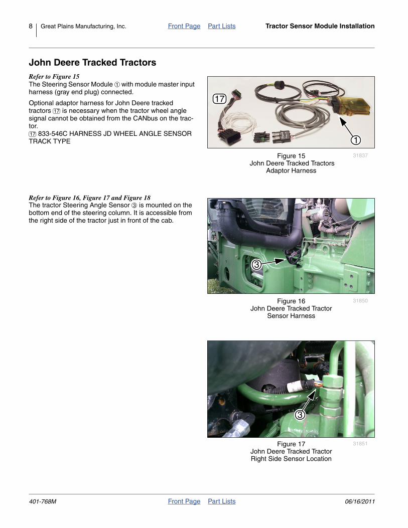
John Deere Tracked TractorsRefer to Figure 15The Steering Sensor Module with module master inputharness (gray end plug) connected.
Optional adaptor harness for John Deere trackedtractors is necessary when the tractor wheel anglesignal cannot be obtained from the CANbus on the trac-tor.
833-546C HARNESS JD WHEEL ANGLE SENSORTRACK TYPE
Null4:
Refer to Figure 16, Figure 17 and Figure 18The tractor Steering Angle Sensor is mounted on thebottom end of the steering column. It is accessible fromthe right side of the tractor just in front of the cab.
Null4:
Null4:
Figure 15 John Deere Tracked Tractors
Adaptor Harness
31837
1
17
1
17
17
Null4:
Figure 16John Deere Tracked Tractor
Sensor Harness
31850
3
3
Null4:
Figure 17John Deere Tracked TractorRight Side Sensor Location
31851
3
401-768M Front Page Part Lists 06/16/2011
Installation Front Page Part Lists Great Plains Manufacturing, Inc. 9
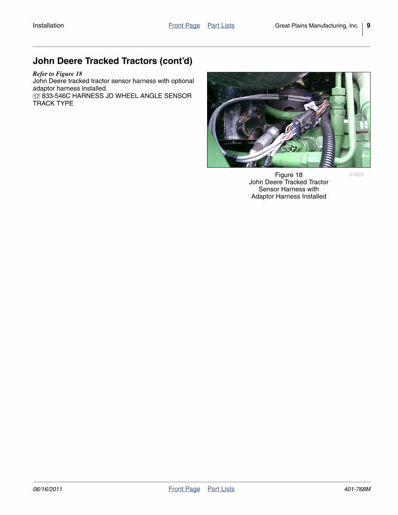
John Deere Tracked Tractors (cont’d)Refer to Figure 18John Deere tracked tractor sensor harness with optionaladaptor harness installed.
833-546C HARNESS JD WHEEL ANGLE SENSORTRACK TYPE
Null4:
Figure 18John Deere Tracked Tractor
Sensor Harness withAdaptor Harness Installed
31829
17
06/16/2011 Front Page Part Lists 401-768M
10 Great Plains Manufacturing, Inc. Front Page Part Lists Tractor Sensor Module Installation
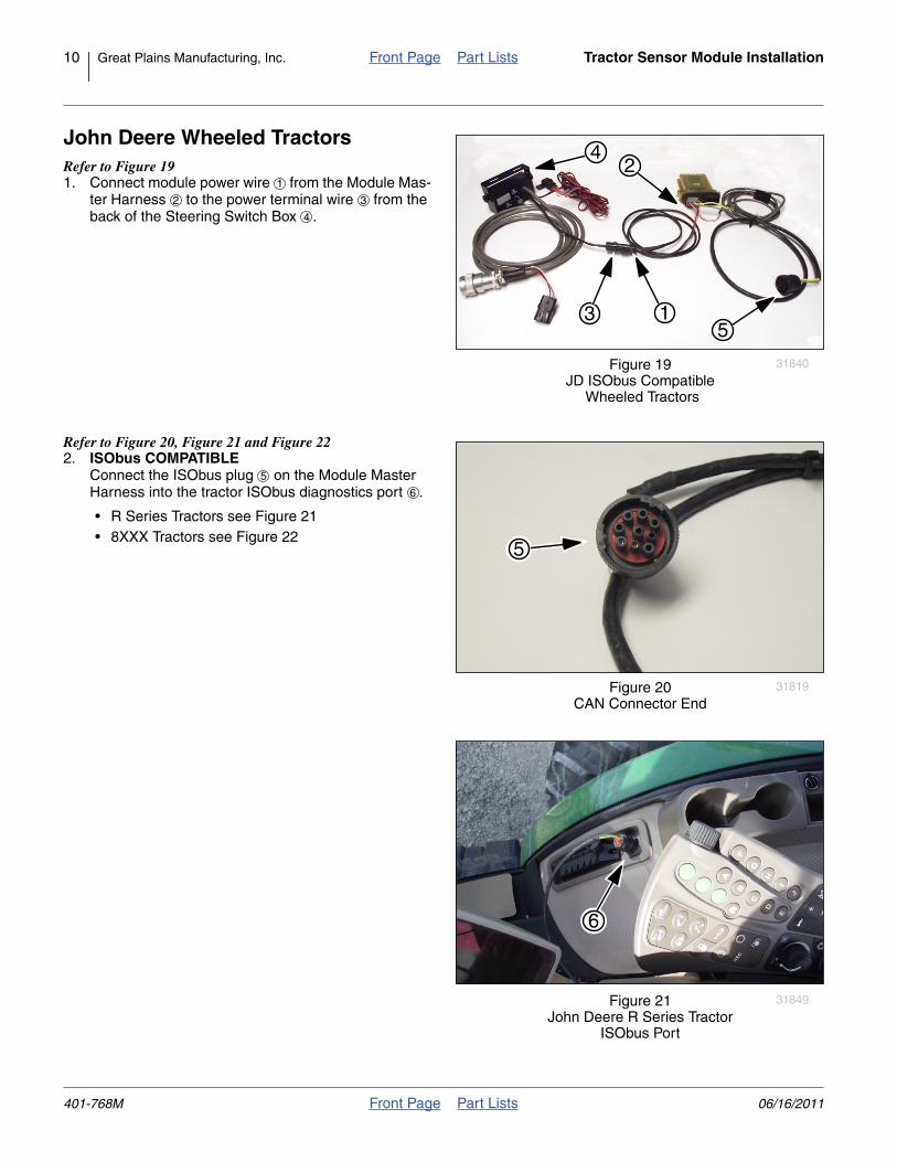
John Deere Wheeled TractorsRefer to Figure 191. Connect module power wire from the Module Mas-
ter Harness to the power terminal wire from theback of the Steering Switch Box .
Null4:
Refer to Figure 20, Figure 21 and Figure 222. ISObus COMPATIBLE
Connect the ISObus plug on the Module MasterHarness into the tractor ISObus diagnostics port .
• R Series Tractors see Figure 21• 8XXX Tractors see Figure 22
Null4:
Null4:
Figure 19JD ISObus Compatible
Wheeled Tractors
31840
1
4
35
21
2 3
4
Null4:
Figure 20CAN Connector End
31819
5
5
6
Null4:
Figure 21John Deere R Series Tractor
ISObus Port
31849
6
401-768M Front Page Part Lists 06/16/2011
Installation Front Page Part Lists Great Plains Manufacturing, Inc. 11
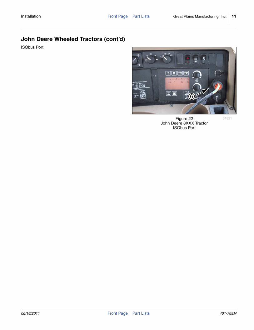
John Deere Wheeled Tractors (cont’d)ISObus Port
Null4:
Figure 22John Deere 8XXX Tractor
ISObus Port
31821
6
06/16/2011 Front Page Part Lists 401-768M
12 Great Plains Manufacturing, Inc. Front Page Part Lists Tractor Sensor Module Installation
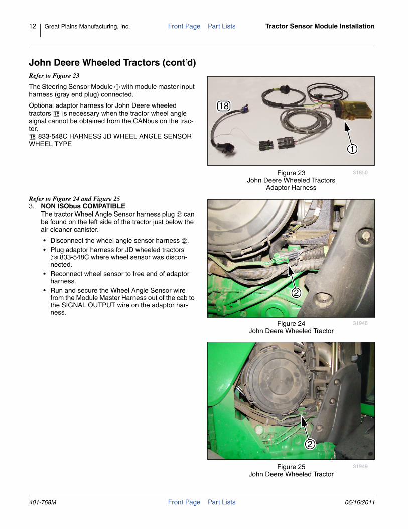
John Deere Wheeled Tractors (cont’d)Refer to Figure 23
The Steering Sensor Module with module master inputharness (gray end plug) connected.
Optional adaptor harness for John Deere wheeledtractors is necessary when the tractor wheel anglesignal cannot be obtained from the CANbus on the trac-tor.
833-548C HARNESS JD WHEEL ANGLE SENSORWHEEL TYPE
Refer to Figure 24 and Figure 253. NON ISObus COMPATIBLE
The tractor Wheel Angle Sensor harness plug canbe found on the left side of the tractor just below theair cleaner canister.
• Disconnect the wheel angle sensor harness .• Plug adaptor harness for JD wheeled tractors
833-548C where wheel sensor was discon-nected.
• Reconnect wheel sensor to free end of adaptorharness.
• Run and secure the Wheel Angle Sensor wirefrom the Module Master Harness out of the cab tothe SIGNAL OUTPUT wire on the adaptor har-ness.
Null4:
Figure 23John Deere Wheeled Tractors
Adaptor Harness
31850
18
1
1
18
18
Null4:
Figure 24John Deere Wheeled Tractor
31948
2
2
2
18
Null4:
Figure 25John Deere Wheeled Tractor
31949
2
401-768M Front Page Part Lists 06/16/2011
Installation Front Page Part Lists Great Plains Manufacturing, Inc. 13
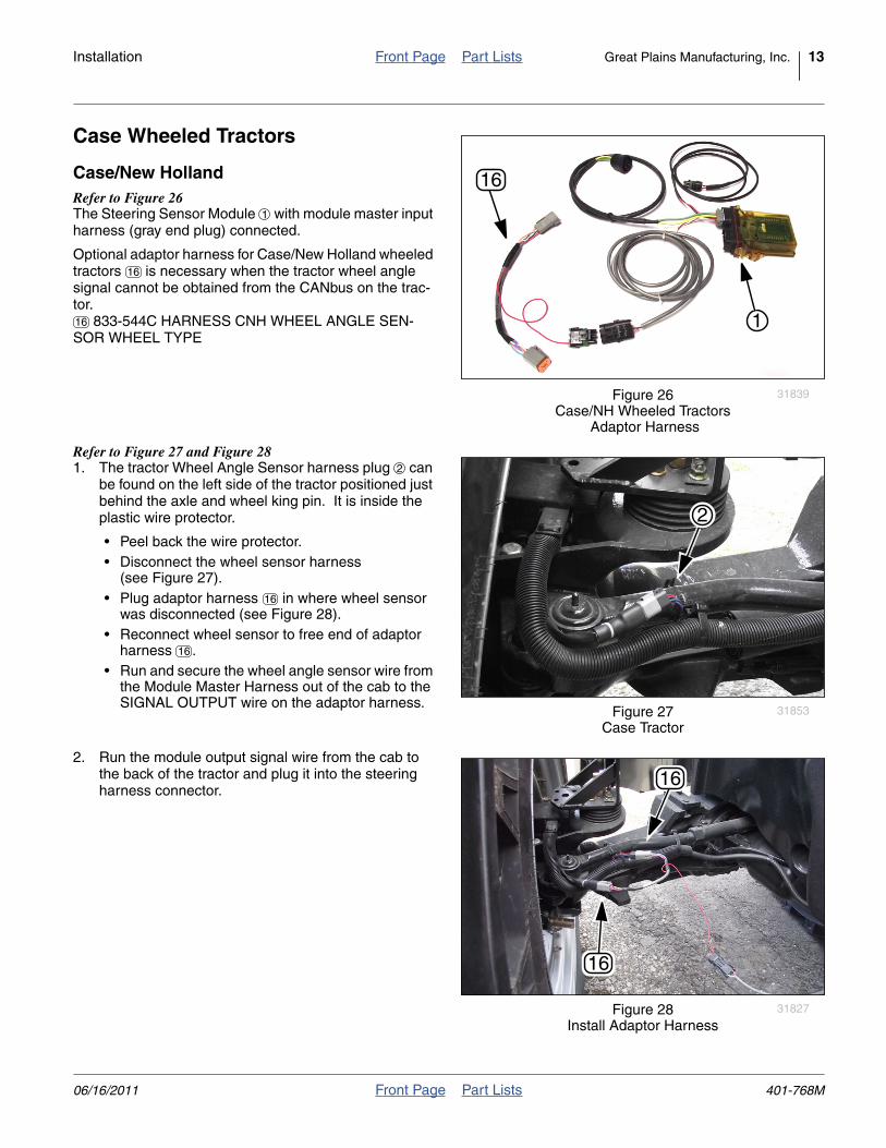
Case Wheeled Tractors
Case/New HollandRefer to Figure 26The Steering Sensor Module with module master inputharness (gray end plug) connected.
Optional adaptor harness for Case/New Holland wheeledtractors is necessary when the tractor wheel anglesignal cannot be obtained from the CANbus on the trac-tor.
833-544C HARNESS CNH WHEEL ANGLE SEN-SOR WHEEL TYPE
Refer to Figure 27 and Figure 281. The tractor Wheel Angle Sensor harness plug can
be found on the left side of the tractor positioned justbehind the axle and wheel king pin. It is inside theplastic wire protector.
• Peel back the wire protector.• Disconnect the wheel sensor harness
(see Figure 27).• Plug adaptor harness in where wheel sensor
was disconnected (see Figure 28).• Reconnect wheel sensor to free end of adaptor
harness .• Run and secure the wheel angle sensor wire from
the Module Master Harness out of the cab to theSIGNAL OUTPUT wire on the adaptor harness.
2. Run the module output signal wire from the cab tothe back of the tractor and plug it into the steeringharness connector.
Null4:
Figure 26Case/NH Wheeled Tractors
Adaptor Harness
31839
16
1
1
16
16
Null4:
Figure 27Case Tractor
31853
2
2
16
16
Null4:
Figure 28Install Adaptor Harness
31827
16
16
06/16/2011 Front Page Part Lists 401-768M
14 Front Page Part Lists
Appendix
Part Lists
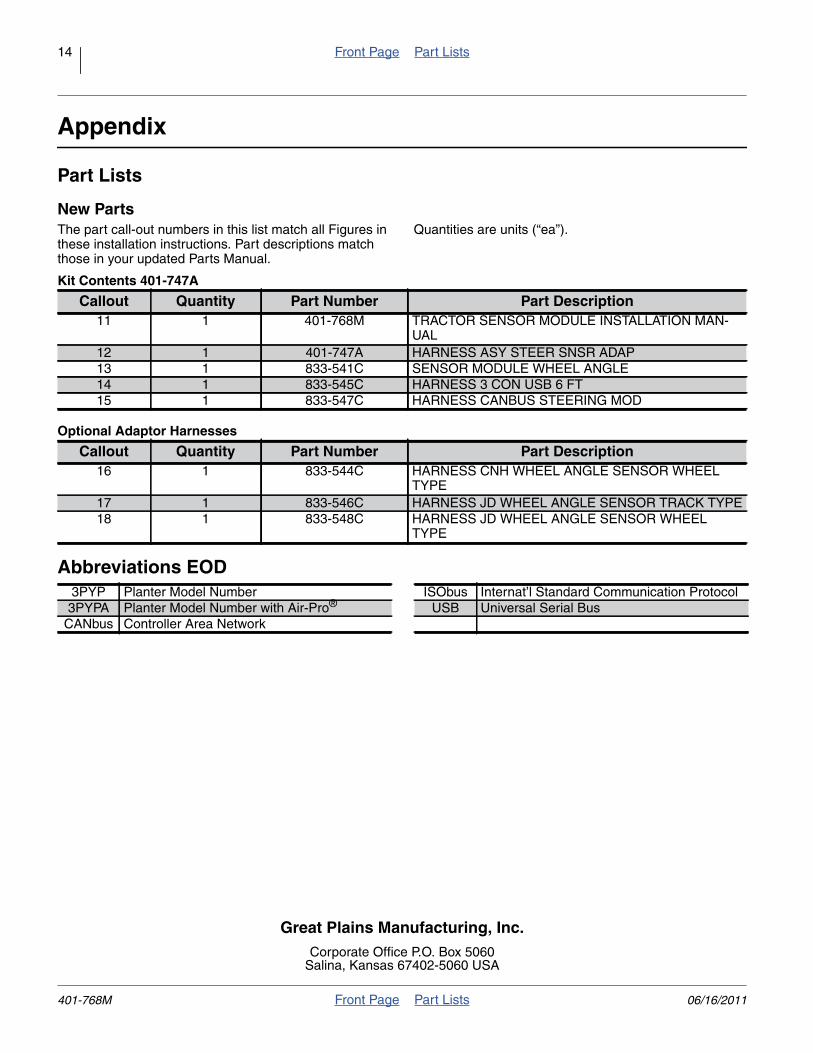
New PartsThe part call-out numbers in this list match all Figures inthese installation instructions. Part descriptions matchthose in your updated Parts Manual.
Quantities are units (“ea”).
Kit Contents 401-747A
Optional Adaptor Harnesses
Abbreviations EOD
Callout Quantity Part Number Part Description11 1 401-768M TRACTOR SENSOR MODULE INSTALLATION MAN-
UAL12 1 401-747A HARNESS ASY STEER SNSR ADAP13 1 833-541C SENSOR MODULE WHEEL ANGLE14 1 833-545C HARNESS 3 CON USB 6 FT15 1 833-547C HARNESS CANBUS STEERING MOD
Callout Quantity Part Number Part Description16 1 833-544C HARNESS CNH WHEEL ANGLE SENSOR WHEEL
TYPE17 1 833-546C HARNESS JD WHEEL ANGLE SENSOR TRACK TYPE18 1 833-548C HARNESS JD WHEEL ANGLE SENSOR WHEEL
TYPE
3PYP Planter Model Number ISObus Internat’l Standard Communication Protocol3PYPA Planter Model Number with Air-Pro® USB Universal Serial Bus
CANbus Controller Area Network
Great Plains Manufacturing, Inc.Corporate Office P.O. Box 5060
Salina, Kansas 67402-5060 USA
401-768M Front Page Part Lists 06/16/2011