TRACKING LOCAL BRITTLE ZONE IN THE HEAT AFFECTED ZONE …
14
* Corresponding author, tel: +234 805 426 9424 TRACKING LOCAL BRITTLE ZONE IN THE HEAT AFFECTED ZONE OF GIRTH-WELDED API 5L X46 PIPE M. O. H. Amuda 1 , L. O. Osoba 2, *, N. N. Etuk 3 , T. F. Lawal 4 and A. O. Adetayo 5 1, 2 ,3 ,4, MATERIALS DEVELOPMENT AND PROCESSING RESEARCH GROUP (MADEPREG), DEPARTMENT OF METALLURGICAL AND MATERIALS ENGINEERING, UNIVERSITY OF LAGOS, AKOKA, LAGOS STATE, NIGERIA 5, MIDWAL ENGINEERING SERVICES LIMITED, 5B ELEGANZA MALL, IKOTA, 101245, LAGOS STATE, NIGERIA E-mail addresses: 1 [email protected], 2 [email protected], 3 [email protected], 4 [email protected], 5 [email protected] ABSTRACT In this study, microhardness variation as well as macro and micro structural examination of the heat affected zone (HAZ) of a girth welded API 5L X46 pipeline material were conducted as a means of tracking local brittle zone (LBZ) in the HAZ region. The weldment analysed were built from heat input range of 695 J/mm – 2567 J/mm. Analysis of the results revealed that the HAZ profile changes with variation in the heat input and becomes shallow but wider as the heat input increases. Defects free welds were achieved under the heat input range of 1650 J/mm – 2017 J/mm welding condition. Localized high hardness values were obtained at certain locations within the HAZ of intermediate heat input welds produced at 1467 J/mm due to thermal stresses induced strains at this heat input in the resolidified weld. Other than this, non-equilibrium rapid heating/cooling that is common during welding as well as the magnitude of mechanical strain generated on cooling vary with heat input and was attributed to the development of high hardness value at localized region within the HAZ of the welds in low heat input welding condition. The macrographic profile at these locations, contrasted against that of a failed pipeline material of similar specification obtained from typical oil and gas infrastructure, established that crack initiation and propagation followed the trend of microhardness variations in the girth welded pipe. The crack initiates at specific location in the HAZ with very high hardness in the range 186-216 Hv within a radius of about 3-5 mm from the edge of the fusion zone. Keywords: API 5L X46; Girth welding; Heat input; Heat affected zone; Local brittle zones 1. INTRODUCTION For many years, researchers pursued the need to develop strong, ductile pipeline material for convenient transportation of pressurized fluid in the oil and gas industry. This led to the design and development of API 5L steel series particularly the X46 for the construction of pipeline infrastructure for oil and gas conveyance [1]. These materials are credited with improved toughness and better microstructural homogeneity than the conventional plain carbon steels of the same composition, which make them suitable and applicable in very hostile on-shore and off-shore environments [2]. Therefore, several tonnages of this steel grade have been used globally in the oil and gas industries especially in the Nigeria’s Niger-Delta creek and other parts of the country [3]. Recently, catastrophic failure of the material has been reported resulting in sudden shut down of the entire crude oil conveying system in the Niger-Delta creek. This failure has been attributed in some quarters to vandalism but preliminary field inspection revealed that some of the reported failures are due to rupture in the pipeline network owing to the development of LBZs in the HAZ of the welded API 5L X46 pipeline material. These LBZs are discrete microstructural regions within the HAZ at certain orientation to the weld line which Nigerian Journal of Technology (NIJOTECH) Vol. 39, No. 2, April 2020, pp. 403 - 416 Copyright© Faculty of Engineering, University of Nigeria, Nsukka, Print ISSN: 0331-8443, Electronic ISSN: 2467-8821 www.nijotech.com http://dx.doi.org/10.4314/njt.v39i2.10
Transcript of TRACKING LOCAL BRITTLE ZONE IN THE HEAT AFFECTED ZONE …

* Corresponding author, tel: +234 805 426 9424
TRACKING LOCAL BRITTLE ZONE IN THE HEAT AFFECTED
ZONE OF GIRTH-WELDED API 5L X46 PIPE
M. O. H. Amuda1, L. O. Osoba2,*, N. N. Etuk3, T. F. Lawal4 and A. O. Adetayo5 1, 2 ,3 ,4, MATERIALS DEVELOPMENT AND PROCESSING RESEARCH GROUP (MADEPREG), DEPARTMENT OF
METALLURGICAL AND MATERIALS ENGINEERING, UNIVERSITY OF LAGOS, AKOKA, LAGOS STATE, NIGERIA 5, MIDWAL ENGINEERING SERVICES LIMITED, 5B ELEGANZA MALL, IKOTA, 101245, LAGOS STATE, NIGERIA
E-mail addresses: 1 [email protected], 2 [email protected], 3 [email protected], 4 [email protected], 5 [email protected]
ABSTRACT
In this study, microhardness variation as well as macro and micro structural examination of the
heat affected zone (HAZ) of a girth welded API 5L X46 pipeline material were conducted as a means
of tracking local brittle zone (LBZ) in the HAZ region. The weldment analysed were built from heat
input range of 695 J/mm – 2567 J/mm. Analysis of the results revealed that the HAZ profile changes
with variation in the heat input and becomes shallow but wider as the heat input increases. Defects
free welds were achieved under the heat input range of 1650 J/mm – 2017 J/mm welding
condition. Localized high hardness values were obtained at certain locations within the HAZ of
intermediate heat input welds produced at 1467 J/mm due to thermal stresses induced strains at
this heat input in the resolidified weld. Other than this, non-equilibrium rapid heating/cooling that
is common during welding as well as the magnitude of mechanical strain generated on cooling vary
with heat input and was attributed to the development of high hardness value at localized region
within the HAZ of the welds in low heat input welding condition. The macrographic profile at these
locations, contrasted against that of a failed pipeline material of similar specification obtained from
typical oil and gas infrastructure, established that crack initiation and propagation followed the
trend of microhardness variations in the girth welded pipe. The crack initiates at specific location
in the HAZ with very high hardness in the range 186-216 Hv within a radius of about 3-5 mm from
the edge of the fusion zone.
Keywords: API 5L X46; Girth welding; Heat input; Heat affected zone; Local brittle zones
1. INTRODUCTION
For many years, researchers pursued the need to
develop strong, ductile pipeline material for
convenient transportation of pressurized fluid in the oil
and gas industry. This led to the design and
development of API 5L steel series particularly the X46
for the construction of pipeline infrastructure for oil
and gas conveyance [1]. These materials are credited
with improved toughness and better microstructural
homogeneity than the conventional plain carbon steels
of the same composition, which make them suitable
and applicable in very hostile on-shore and off-shore
environments [2]. Therefore, several tonnages of this
steel grade have been used globally in the oil and gas
industries especially in the Nigeria’s Niger-Delta creek
and other parts of the country [3]. Recently,
catastrophic failure of the material has been reported
resulting in sudden shut down of the entire crude oil
conveying system in the Niger-Delta creek. This failure
has been attributed in some quarters to vandalism but
preliminary field inspection revealed that some of the
reported failures are due to rupture in the pipeline
network owing to the development of LBZs in the HAZ
of the welded API 5L X46 pipeline material. These
LBZs are discrete microstructural regions within the
HAZ at certain orientation to the weld line which
Nigerian Journal of Technology (NIJOTECH)
Vol. 39, No. 2, April 2020, pp. 403 - 416
Copyright© Faculty of Engineering, University of Nigeria, Nsukka, Print ISSN: 0331-8443, Electronic ISSN: 2467-8821
www.nijotech.com
http://dx.doi.org/10.4314/njt.v39i2.10
TRACKING LOCAL BRITTLE ZONE IN THE HEAT AFFECTED ZONE OF GIRTH-WELDED API 5L X46 PIPE, M.O.H. Amuda, et al
Nigerian Journal of Technology, Vol. 39, No. 2 April 2020 404
exhibit significantly lower resistance to fracture than
surrounding material. LBZs do manifest in crack
initiation and then propagate to the parent plate due
to high circumferential pressure externally exerted by
the fluid; and consequently, failure occurs. LBZs
behaviour is usually associated with initiation by
cleavage, but inter-granular fracture has been
observed in some instances [4]. Investigations have
shown that LBZs in multi-pass welds of API 5L X46
pipeline steels grade can be either in the grain
coarsened heat affected zone (GCHAZ) close to the
weld fusion boundary or the inter-critically reheated
grain coarsened heat affected zone (ICGCHAZ).
Although low toughness regions could be present at
the boundary between the inter-critical and subcritical
heat affected zone (IC/SCHAZ). This is often due to
locally intensified strain ageing at a pre-existing crack
tip in parent plate, HAZ or weld metal, or within the
welds metal itself. But the term is not usually used to
describe these cases [5]. LBZs behaviour depends
primarily on steel chemistry, welding procedure,
welding heat input, and post-weld heat treatment
condition [6]. According to BS 7448 [7], the size of a
LBZ is a function of welding heat input and the
coarsening behaviour of the steel. But, it can be
typically, less than 0.5 to 1.0 mm in height and can
extend parallel to the weld over a distance of tens of
millimetres. The length depends on welding process,
weld straightness and frequency of stop/starts. A
number of approaches have been adopted by several
researchers towards tracking and eliminating LBZs in
the HAZ of API 5L steel grade pipeline materials. These
include; describing heat inputs condition that needs to
be evaluated; modifying the angle of attack between
electrodes and the fusion face; modifying weld bead
overlap and size to maximize HAZ refinement [8].
Yet, in spite of diligent compliance to all these
approaches to track and eliminate LBZs, failures still
occur resulting from the presence of LBZs in HAZ
which is an indication that the process is not yet
optimized. Therefore, additional investigation is
deemed necessary to achieve better strategy for
tracking LBZs in HAZ of welded API 5L materials
particularly the X46 grade. Thus, the current study is
a carefully design experimental investigation to track
the evolution and manifestation of LBZs within the
HAZ with a view to establishing an understanding for
the development of a framework to mitigate the
development of the phenomena in this girth welded
pipeline material.
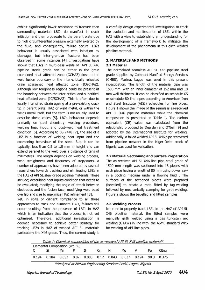
2. MATERIALS AND METHODS
2.1 Material
The normalized seamless API 5L X46 pipeline steel
grade supplied by Compact Manifold Energy Services
(CMES), Marina, Lagos was used in this present
investigation. The length of the material pipe was
1500 mm with an inner diameter of 152 mm and 10
mm wall thickness. It can be classified as schedule XS
or schedule 80 line pipes according to American Iron
and Steel Institute (AISI) schedules for line pipes.
Figure 1 shows the image of the seamless as-received
API 5L X46 pipeline materials while the chemical
composition is presented in Table 1. The carbon
equivalent (CE) value was calculated from the
relationship proposed by Dearden and O'Neill [9] and
adopted by the International Institute for Welding.
Additionally, a failed welded API 5L X46 pipe recovered
from pipeline network in the Niger-Delta creek of
Nigeria was used for validation.
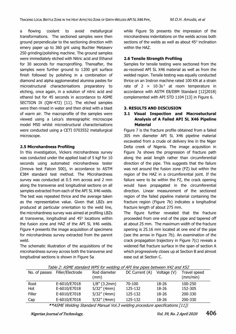
2.2 Material Sectioning and Surface Preparation
The as-received API 5L X46 line pipe steel grade of
1500 mm length was sectioned into 18 pieces with
each piece having a length of 80 mm using power saw
in a cooling medium under a flowing fluid . The
surfaces of the sectioned pieces were prepared
(bevelled) to create a root, fitted by tag-welding
followed by mechanically clamping for girth welding.
Figure 2 shows the bevelled and fitted samples.
2.3 Welding Process
In order to properly track LBZs in the HAZ of API 5L
X46 pipeline material, the fitted samples were
manually girth welded using a gas tungsten arc
welding (GTAW) in line with the ASME standard WPS
for welding of API line pipes.
Table 1: Chemical composition of the as-received API 5L X46 pipeline material*
Elemental Composition (wt. %)
C Si Mn P S Cr Ni Mo V Fe CEIIW
0.194 0.184 0.652 0.02 0.003 0.12 0.043 0.037 0.194 98.3 0.376
*Analysed at Midwal Engineering Services Lekki, Lagos, Nigeria

TRACKING LOCAL BRITTLE ZONE IN THE HEAT AFFECTED ZONE OF GIRTH-WELDED API 5L X46 PIPE, M.O.H. Amuda, et al
Nigerian Journal of Technology, Vol. 39, No. 2 April 2020 405
Figure 1: Image of the as-received API 5L X46 pipeline material
Figure 2: Bevelled and fitted samples (a) bevelled Surfaces (b) fitted samples
In its basic form, heat input Q (J/mm) delivered
during the welding process is dependent on the
power of the welding heat source P (W), and welding
speed, ν (mm/min), through Eqn. (1) [10].
(1)
where k is a constant known as process or efficiency
factor. Accordingly, the magnitude of welding heat
input can be varied by either changing the power or
welding speed. Therefore, welding current and travel
speed were varied at three different treatment levels.
Table 2 gives a typical ASME standard welding
procedure specification (QW-482) as per ASME
SECTION IX [11] for welding of API line pipes
between X42 and X52 with outside diameter in the
range 60.325mm to 323.85mm and wall thickness in
the range 5 mm to 19 mm.
However, given that LBZ failures are often produced
from prevailing procedure specification, the current
study chooses to carry out experimental investigation
outside the existing specification. As such, arc current
in the range 80 - 140A and travel speed range 72 –
152 mm/min are the modified process parameters
employed. Table 3 shows the number of weld joints
and the corresponding combinations of process
parameters at different levels used in this
investigation.
Table 4 gives in details, the number of weld samples,
process combination of the welding parameters used
and the resulting heat input variation.
GTAW was adopted for both the preliminary passes
and the filler and weld cap passes at heat input
ranging from 695J/mm to 2567J/mm, corresponding
to the ranges of welding current between 80A-140A;
and travel speed between 72 mm/min and 152
mm/min. Direct current electrode negative polarity
(DCEN) with argon as shielding gas was used for the
GTAW. Figure 3 shows the welding process at 6G
position and the resulting weld specimens at different
welding conditions.
2.4 Macro and Microstructural Examination of
the Weldments
Macrographs as well as micrographs of the
weldments were taken in order to examine the weld
and HAZ profile of the API 5L X46 pipeline material
weldments at different welding conditions. The
samples for metallographic examination were
extracted from the weldments and carefully sectioned
to achieve a uniform flat surface. Sectioning
procedure was carried out in a cooling medium under
PQ
TRACKING LOCAL BRITTLE ZONE IN THE HEAT AFFECTED ZONE OF GIRTH-WELDED API 5L X46 PIPE, M.O.H. Amuda, et al
Nigerian Journal of Technology, Vol. 39, No. 2 April 2020 406
a flowing coolant to avoid metallurgical
transformations. The sectioned samples were then
ground perpendicular to the sectioning direction with
emery paper up to 360 grit using Buchler Metaserv
250 grinding/polishing machine. The ground samples
were immediately etched with Nitric acid and Ethanol
for 30 seconds for macroprofiling. Thereafter, the
samples were further ground to 1200 grit surface
finish followed by polishing in a combination of
diamond and alpha agglomerated alumina pastes for
microstructural characterisations preparatory to
etching, once again, in a solution of nitric acid and
ethanol but for 45 seconds in accordance to ASME
SECTION IX (QW-472) [11]. The etched samples
were then rinsed in water and then dried with a blast
of warm air. The macroprofile of the samples were
viewed using a Leica’s stereographic microscope
model M50 whilst microstructural characterisations
were conducted using a CETI 0703552 metallurgical
microscope.
2.5 Microhardness Profiling
In this investigation, Vickers microhardness survey
was conducted under the applied load of 5 kgf for 10
seconds using automated microhardness tester
(Innova test Falcon 500), in accordance to ASTM
E384 standard test method. The Microhardness
survey was conducted at 0.5 mm across and 2 mm
along the transverse and longitudinal sections on all
samples extracted from each of the API 5L X46 welds.
The test was repeated thrice and the average taken
as the representative value. Given that LBZs are
produced at particular orientation to the weld line,
the microhardness survey was aimed at profiling LBZs
at transverse, longitudinal and 45o locations within
the fusion zone and HAZ of the API 5L X46 welds.
Figure 4 presents the image acquisition of specimens
for microhardness survey extracted from the parent
weld.
The schematic illustration of the acquisitions of the
microhardness survey across both the transverse and
longitudinal sections is shown in Figure 5a
while Figure 5b presents the impression of the
microhardness indentations on the welds across both
sections of the welds as well as about 45o inclination
within the HAZ.
2.6 Tensile Strength Profiling
Samples for tensile testing were sectioned from the
as-received API 5L X46 material as well as from the
welded region. Tensile testing was equally conducted
thrice on an Instron machine rated 100 KN at a strain
rate of 2 × 10⁻³s-1 at room temperature in
accordance with ASTM E8/E8M Standard [12]2018)
complemented with API STD 1104 [13] in Figure 6.
3. RESULTS AND DISCUSION
3.1 Visual Inspection and Macrostuctural
Analysis of A Failed API 5L X46 Pipeline
Material
Figure 7 is the fracture profile obtained from a failed
305 mm diameter API 5L X46 pipeline material
excavated from a crude oil delivery line in the Niger
Delta creek of Nigeria. The image acquisition in
Figure 7a shows the progression of fracture path
along the axial length rather than circumferential
direction of the pipe. This suggests that the failure
was not around the fusion zone (FZ) but within the
region of the HAZ in a circumferential joint. If the
failure were to be within the FZ, the crack opening
would have propagated in the circumferential
direction. Linear measurement of the sectioned
region of the failed pipeline material containing the
fracture region (Figure 7b) indicates a longitudinal
fracture length of about 275 mm.
The figure further revealed that the fracture
proceeded from one end of the pipe and tapered off
at about 25 mm. The maximum width of the fracture
opening is 25.16 mm located at one end of the pipe
(see the arrow in Figure 7b). An examination of the
crack propagation trajectory in Figure 7(c) reveals a
widened flat fracture surface in the span of section A
which progressively closes up at Section B and almost
ease out at Section C.
Table 2: ASME standard WPS for welding of API line pipes between X42 and X52
No. of passes Filler/Electrode Rod diameter
(mm)
DC Current (A) Voltage (V) Travel speed
(mm/min)
Root E-6010/E7018 1/8” (3.2mm) 70-100 18-26 100-250 Hot E-6010/E7018 5/32” (4mm) 125-132 18-26 152-305
Filler E-6010/E7018 5/32” (4mm) 125-132 18-26 200-330
Cap E-6010/E7018 5/32” (4mm) 125-132 18-26 200-330
**ASME Welding Standard Manual Vol.3 welding procedure specifications [11])

TRACKING LOCAL BRITTLE ZONE IN THE HEAT AFFECTED ZONE OF GIRTH-WELDED API 5L X46 PIPE, M.O.H. Amuda, et al
Nigerian Journal of Technology, Vol. 39, No. 2 April 2020 407
Table 3: Welding variables and their treatment levels
Number Weld Joints (N) Welding Current (Amps) Travel Speed (mm/min)
1 80 72
2 80 112
3 80 152
4 110 72
5 110 112
6 110 152
7 140 72
8 140 112
9 140 152
Table 4: Process parameters combination and heat inputs (with k =60)
Welding Samples
Welding Current (Amps)
Travel Speed (mm/min)
Arc Voltage (Volts)
Heat Input (J/mm)
Sample A 80 72 22 1467 (M)
Sample B 80 112 22 943 (L)
Sample C 80 152 22 695 (L)
Sample D 110 72 22 2017 (H)
Sample E 110 112 22 1296 (M)
Sample F 110 152 22 955.3(L)
Sample G 140 72 22 2567 (H)
Sample H 140 112 22 1650 (H)
Sample I 140 152 22 1216 (M)
L = low level; M = mid-point or intermediate level; H = high level
Figure 3: Gas tungsten arc welding process: (a) welding of specimens at 6G position and
(b) weld specimens
Figure 4: Image acquisition of specimens extracted from the weldments for microhardness profiling

TRACKING LOCAL BRITTLE ZONE IN THE HEAT AFFECTED ZONE OF GIRTH-WELDED API 5L X46 PIPE, M.O.H. Amuda, et al
Nigerian Journal of Technology, Vol. 39, No. 2 April 2020 408
Figure 5: Illustration of microhardness indentation positions on the API 5L X46 girth welds: (a) schematic
illustration and (b) image presentation of actual indentation positions
Figure 6: Tensile test specimens extracted from API
5L X46 weld coupons
This implies that crack propagation is rapid in Section
A and slows down around and beyond Section B. Crack
dynamics of this nature approximate brittle fracture
consistent with fatigue loading.
Further validation of Section A via the evaluation of
the microhardness of the region shown in Figure 8
established the presence of points within the HAZ
exhibiting a sharp increase in microhardness values in
the range 250 – 325 HV unlike the average value of
225 HV in the weld metal (FZ). These points are
between 2.5 mm and 3.5 mm from the FZ.
3.2 Analysis of Macroprofiles of Weld Coupons
The macrographs showing the weld profiles of the
coupons produced at different heat inputs using GTAW
are presented in Figure 9 .The range of heat input
investigated was divided into three classifications and
these are: heat input in the range 695J/mm-
955.3J/mm(less than 1000 J/mm as low heat input,
those greater than 1000 J/mm but less than 1500
J/mm (1216J/mm-1467J/mm) is classified as
intermediate heat input and those greater than 1500
J/mm (1650J/mm-2567J/mm) are classified as high
heat input. The macrographs revealed that the HAZ
profile is affected by changes in the heat input. In
specifics, as the heat input changed from low to
medium and high heat input, the weld profile assumed
a shallow depth in the thickness direction with a large
surface width in addition to a progressively widened
HAZ region (see Figure 9a-c). The trend of the weld
profile with change in heat input is similar to previously
reported work by Richards et al. [14]. Though, the size
of the HAZ increases as the heat input transits from
low to intermediate and high heat inputs but the depth
of penetration significantly becomes shorter. Indeed,
for the intermediate and high heat input weld
coupons, a prior root cap was deposited for full weld
penetration to be accomplished (see Figure 9b and
9c). Thus, low heat input appears to deliver better
weld shape and size in terms of width, penetration
depth and minimal geometrical distortion in the
welded coupons.
3.3 Microstructural Analysis of Weld Coupons
The microstructure of the as-received API 5L X46
pipeline steel grade shown in Figure 10 consists of
ferrite matrix and dark patches of pearlite.
Indentation at 45O
to the weld line
TRACKING LOCAL BRITTLE ZONE IN THE HEAT AFFECTED ZONE OF GIRTH-WELDED API 5L X46 PIPE, M.O.H. Amuda, et al
Nigerian Journal of Technology, Vol. 39, No. 2 April 2020 409
Microstructural analyses of the weld coupons
produced at different heat inputs could be used to
evaluate the influence of heat input on microstructural
inhomogeneity in the welds which facilitates the
development of LBZs in the HAZ. The micrographs of
the welds at various heat inputs shown in Figure 11-
13 clearly reveal the change in grain morphology in
relation to the heat input. Also, some phase
transformation products were also observed. For weld
coupons at low heat input (less than 1000 J/mm, see
Figure 11), the microstructure in this condition
indicates the formation of equiaxed ferrite matrix in
the FZ and carbides at the HAZ. The typical elongated
columnar structure often obtained in fusion welds was
absent under this condition. This suggests that the
development of columnar structure in fusion welds
may after all be a function of the level of the heat
input. Other microstructural features equaly observed
under this condition of heat input include grain
boundary ferrite (GBF) and grain boundary maternsite
(GBM) (see Figure 11 b and c).
Figure 12 shows the microstructures of weld coupons
produced at intermediate heat input (less than 1500
J/mm). The change in grain structure within the
intermediate heat input in both the FZ and HAZ is not
quite apparent suggetsing that the thermal conditions
within this heat input range is almost the same. But
unlike the equiaxed grain structure in the low heat
input welds, the grain structure in this condition is
esentially columnar (see Figure 12) across the FZ but
more of equiaxed in the HAZ particulalry in the region
adjacent to the FZ line. But at the upper band of the
intermediate heat input (1467 J/mm), small amount of
large ferrite grains and GBM were present (see Figure
12c).
Microstructures of weld produced at high heat input
greater than 1500 J/mm are presented in Figure 13.
The microstucture of weld produced at heat input of
1650 J/mm (Figure 13a) revealed the formation of
acicular ferrite (AF) grain structure. The
microstructure in the welds produced at heat input of
2017 J/mm and 2567 J/mm revealed the formation of
equiaxed grain structures and grain boundary ferrites
in the FZs whereas columnar ferrites grains were
observed in the HAZ. These grain boundary ferrites
could be detrimental to the weld coupons.
AF observed in Figure 13a is a structural
phase of ferrite in steel that is characterised by
needle-shaped crystallites or grains when viewed in
two dimensions. This phase is generally found to be
positive for weld strength and impact toughness [14].
This is accountable for the high yield strength
recorded from the weld during tension test. At higher
heat input rate, microstructural features such as
coarse ferrite grains were also observed. This suggests
that at high heat input, the cooling rate is slow with
transformation of austenite (γ) to α-ferrite.
3.4 Analysis of Mechanical Properties of Weld
Coupons
3.4.1 Microhardness Profiling in the Weld
Specimens
Microhardness survey was performed across the FZ
and the HAZ of grit welded coupons produced at
different heat input conditions. The survey was used
to track LBZs in the HAZ of the material through
comparative analyses of the microhardness at various
regions. The locations both schematic and real time
indentation in which the microhardness survey was
carried out across the weld shown in Figure 5 provide
the total number of indentations acquired in relation
to the traverse and longitudinal directions. .
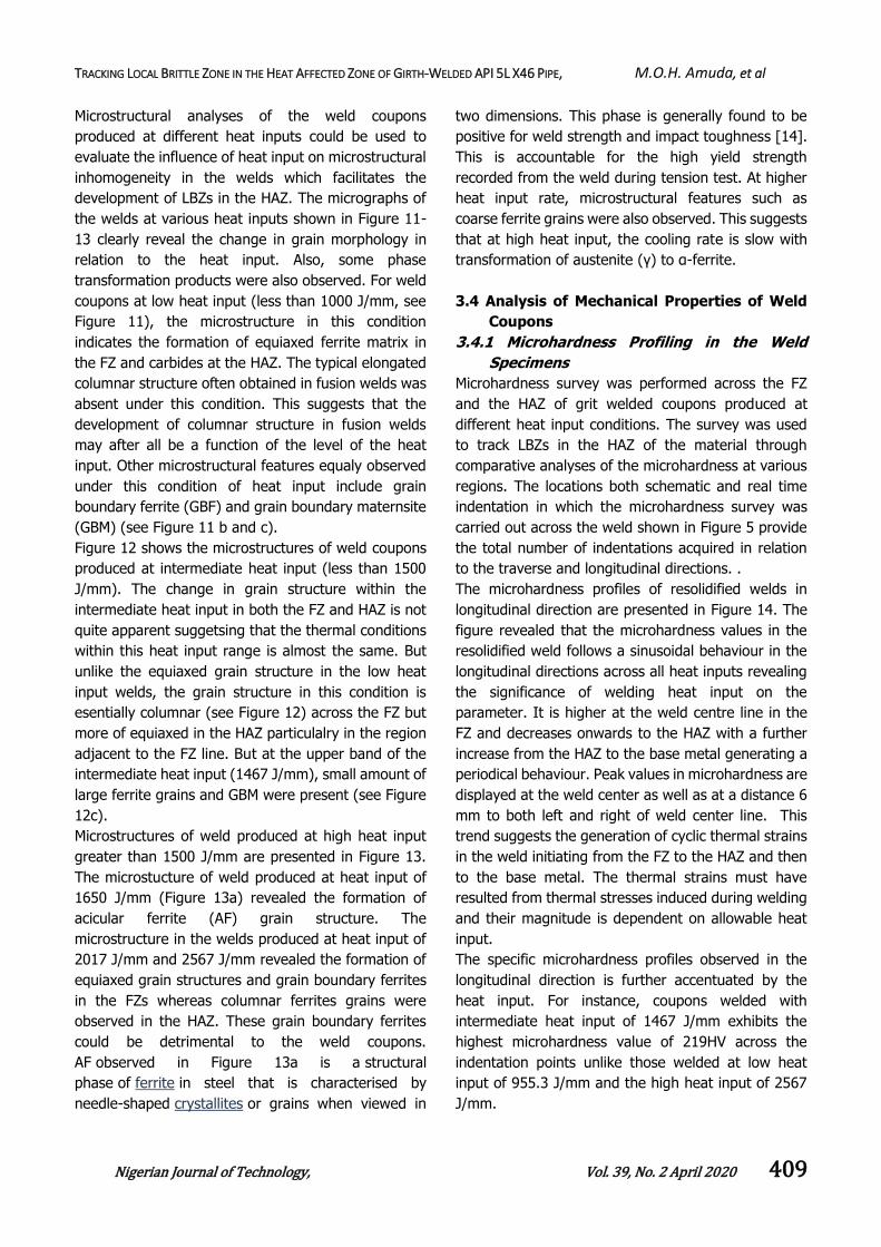
The microhardness profiles of resolidified welds in
longitudinal direction are presented in Figure 14. The
figure revealed that the microhardness values in the
resolidified weld follows a sinusoidal behaviour in the
longitudinal directions across all heat inputs revealing
the significance of welding heat input on the
parameter. It is higher at the weld centre line in the
FZ and decreases onwards to the HAZ with a further
increase from the HAZ to the base metal generating a
periodical behaviour. Peak values in microhardness are
displayed at the weld center as well as at a distance 6
mm to both left and right of weld center line. This
trend suggests the generation of cyclic thermal strains
in the weld initiating from the FZ to the HAZ and then
to the base metal. The thermal strains must have
resulted from thermal stresses induced during welding
and their magnitude is dependent on allowable heat
input.
The specific microhardness profiles observed in the
longitudinal direction is further accentuated by the
heat input. For instance, coupons welded with
intermediate heat input of 1467 J/mm exhibits the
highest microhardness value of 219HV across the
indentation points unlike those welded at low heat
input of 955.3 J/mm and the high heat input of 2567
J/mm.

TRACKING LOCAL BRITTLE ZONE IN THE HEAT AFFECTED ZONE OF GIRTH-WELDED API 5L X46 PIPE, M.O.H. Amuda, et al
Nigerian Journal of Technology, Vol. 39, No. 2 April 2020 410
Figure 7: Images and macroprofile of a failed 305 mm API 5L X46 pipeline material: (a) as-received failed material, (b) crack trajectory in the failed material and (c) magnified sectional view of crack propagation in the
failed material
Figure 8: Hardness trend along Section A (Figure 6c) highlighting points of localised sharp hardness values
Figure 9: Macroprofile API 5L X46 weld coupons at different ranges of heat input: (a) low heat input, (b)
intermediate heat input and (c) high heat input

TRACKING LOCAL BRITTLE ZONE IN THE HEAT AFFECTED ZONE OF GIRTH-WELDED API 5L X46 PIPE, M.O.H. Amuda, et al
Nigerian Journal of Technology, Vol. 39, No. 2 April 2020 411
Figure 10: Micrograph of as-received API 5L X46 material showing ferritic matrix background and dark patches
of pearlite
Figure 11: Micrographs of weld coupons at ranges of low heat input less than 1000 J/mm: (a)
695 J/mm, (b) 943 J/mm and (c) 955 J/mm
The spots of exceptional high microhardness value
are essentially within the HAZ and appear to
approximate the region within the coarse grain HAZ
shown in Figure 7 which was obtained from a failed
API pipeline material of the same composition as the
welded coupons. The trend in the microhardness
values in both the FZ and HAZ in the longitudinal
direction could be attributed to microstructural
transformation and the stress-strain dynamics in the
coupons resulting in the formation of martensite
during the resolidification of the welds.
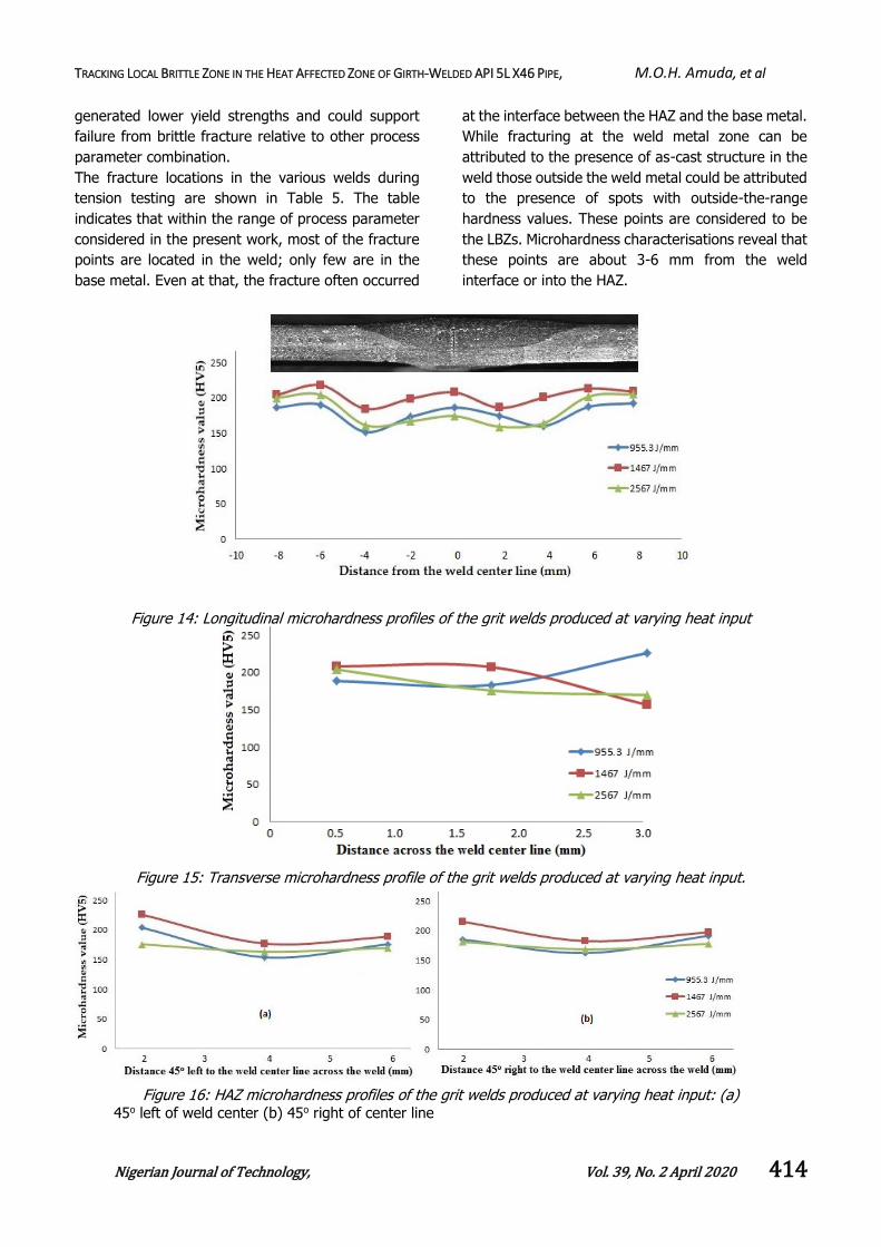
Figure 15 presents the microhardness profiles of the
resolidified welds in the transverse direction. Whilst
the trend is different from that in the longitudinal
direction, it is equally dictated by the welding heat
input. For welds produced at low heat input, the
microhardness value remain almost constant until at
a depth of 1.5 mm beyond which it increased with
depth of penetration. In welds produced at
intermediate heat input, marginal increase in
microhardness value was obtained until at a depth
of about 1.8 mm where a progressive decrease in
microhardness was obtained. Whereas in the welds
produced with high heat input, progressive decrease
in the microhardness value was obtained across the
depth of the welds. A maximum microhardness value
of 230 HV was obtained in welds produced with low
heat input at a depth of 3.0 mm which is higher than
the maximum microhardness value obtainable from
either intermediate or high input condition. The peak
value in intermediate heat input welds is about 220
HV at a depth of 0.5 mm and in high input welds,
200µm

TRACKING LOCAL BRITTLE ZONE IN THE HEAT AFFECTED ZONE OF GIRTH-WELDED API 5L X46 PIPE, M.O.H. Amuda, et al
Nigerian Journal of Technology, Vol. 39, No. 2 April 2020 412
the value is about 207 HV at a depth of 0.5 mm. This
trend of microhardness in the transverse direction is
attributable to differential cooling rate in the
thickness direction due to the varying heat input.
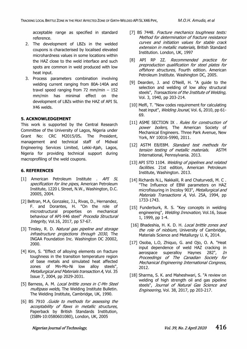
Microhardness behaviour at 45o left and right to the
weld centreline is shown in Figure 16. The figure
shows that the trend is similar to that in the
transverse direction at low heat input condition (955.
3 J/mm). Since the 45o orientation is within the HAZ,
the trend in the microhardness characteristics in the
welded coupons confirms that spots of high
hardness value are restricted within the HAZ. This is
suggestive that LBZs are essentially HAZ
phenomenon. These spots are about 2 mm from the
weld centre line both from the left and right (See
Figure 16a and b) irrespective of the heat input.
The high microhardness variation in the longitudinal
and transverse direction of the welded coupons can
be considered as LBZs. This is reinforced with the
trend in Figure 16. The phenomenon of LBZs have
been previously attributed by Funderburk [15] to be
due to the occurrence of rapid cooling at low heat
input welding condition, while, Bhadeshia [16]
indicated that LBZs are general practical problem
associated with welding of carbon steel pipes.
Similarly, previous work on weld cracking in IN 718
superalloys [17] have shown that cracking generally
occurs when significant amounts of thermal strains
are generated during weld cooling particularly in low
heat input conditions.
Figure 12: Micrographs of weld coupons at ranges of intermediate heat input less than
1500J/mm: (a) 1216 J/mm, (b) 1296 J/mm and (c) 1467 J/mm

TRACKING LOCAL BRITTLE ZONE IN THE HEAT AFFECTED ZONE OF GIRTH-WELDED API 5L X46 PIPE, M.O.H. Amuda, et al
Nigerian Journal of Technology, Vol. 39, No. 2 April 2020 413
Figure 13: Micrographs of weld coupons at ranges of high heat input: (a) 1650 J/mm, (b) 2017 J/mm and (c)
2567 J/mm
Though, the differential cooling rates associated with
the present work has not been evaluated but the
work of Bhadeshia [16] appear to suggest that LBZs
are consequential effect in the welding of ferrous
pipes. Yet, what the present work has demonstrated
is that spots of occasional high hardness may be used
as an indicator of the likelihood of the presence of
LBZs particularly in the regions of the HAZ adjacent
to the weld interface.
3.4.2 Analysis of Weld Tensile Strength
Figure 17 shows the stress-strain distribution in as-
received materials during tension testing for material
verification. The yield and tensile strength of the
material are 450 MPa and 650 MPa, respectively.
These values are within the range specify for API 5L
X46 steel grade for Product Specification Level 2
(PSL2) [18]. However, the trend of these strength
in the welded coupons across the heat inputs is
shown in Figure 18. The figure shows that welding
process parameters have less significant effect on the
tensile strength unlike the yield strength.
The after-weld tensile strength in the coupons
averaged 551 MPa relative to 650MPa in the as-
received base metal. However, the yield strength is
significantly affected by the heat input. The yield
strength progressively decreases with increasing heat
input in the low heat input range (695-955 J/mm) and
maintains a plateau at the intermediate heat input
range (1216-1467 J/mm) beyond which it rises with
increasing heat input in the higher heat input range
increases (1650 -2567 J/mm). In the range of heat
input considered in the present investigation, the
yield strength decreased from 450 MPa in the as-
received base metal to about 331 MPa in the welded
coupons. The trend in the profile of the yield strength
in Figure 18 approximates the behaviour observed in
the crack initiation and propagation trajectory shown
in Figure 7. The trajectory suggests a higher stress
level for crack initiation and a reduced stress level for
propagation particularly in the low heat input range.
This is indicative of ductile flow in the crack initiation
before transiting to a possible brittle fracture which is
accentuated by a combination of environmental
condition and the flow regime of the pressurised fluid
in the pipeline material.
Therefore, the development of isolated spots of high
hardness value (LBZ) as obtained in the HAZ is
considered to have influenced the behaviour of the
welded coupons at different heat inputs particularly
at the intermediate heat input range. In specifics,
heat input in the range 1216 J/mm – 1650 J/mm
TRACKING LOCAL BRITTLE ZONE IN THE HEAT AFFECTED ZONE OF GIRTH-WELDED API 5L X46 PIPE, M.O.H. Amuda, et al
Nigerian Journal of Technology, Vol. 39, No. 2 April 2020 414
generated lower yield strengths and could support
failure from brittle fracture relative to other process
parameter combination.
The fracture locations in the various welds during
tension testing are shown in Table 5. The table
indicates that within the range of process parameter
considered in the present work, most of the fracture
points are located in the weld; only few are in the
base metal. Even at that, the fracture often occurred
at the interface between the HAZ and the base metal.
While fracturing at the weld metal zone can be
attributed to the presence of as-cast structure in the
weld those outside the weld metal could be attributed
to the presence of spots with outside-the-range
hardness values. These points are considered to be
the LBZs. Microhardness characterisations reveal that
these points are about 3-6 mm from the weld
interface or into the HAZ.
Figure 14: Longitudinal microhardness profiles of the grit welds produced at varying heat input
Figure 15: Transverse microhardness profile of the grit welds produced at varying heat input.
Figure 16: HAZ microhardness profiles of the grit welds produced at varying heat input: (a)
45o left of weld center (b) 45o right of center line

TRACKING LOCAL BRITTLE ZONE IN THE HEAT AFFECTED ZONE OF GIRTH-WELDED API 5L X46 PIPE, M.O.H. Amuda, et al
Nigerian Journal of Technology, Vol. 39, No. 2 April 2020 415
Figure 17: Tensile behaviour in as-received API 5L X46 pipeline material
Figure 18: Yield and tensile strengths of welds produced at different heat inputs
Table 5: Fracture points locations in welded coupons produced at different process
parameters
Samples Current (A) Welding Speed (mm/min) Heat Input (J/mm) Fracture Location
A 80 72 1467 Failure in weld metal
B 80 112 943 Failure in weld metal
C 80 152 695 Failure in weld metal
D 110 72 2017 Failure in base metal
E 110 112 1296 Failure in base metal
F 110 152 955.3 Failure in weld metal
G 140 72 2567 Failure in weld metal
H 140 112 1650 Failure in base metal
I 140 152 1216 Failure in base metal
4. CONCLUSION
Microhardness variations in welded API 5L X46
pipeline material produced at varying welding
conditions have been studied to track LBZs in the HAZ
of API 5L X46 pipeline materials and the following
conclusions emerged:
1. The range of process parameters used in the
present work successfully produced defect free
welds with mechanical properties within
TRACKING LOCAL BRITTLE ZONE IN THE HEAT AFFECTED ZONE OF GIRTH-WELDED API 5L X46 PIPE, M.O.H. Amuda, et al
Nigerian Journal of Technology, Vol. 39, No. 2 April 2020 416
acceptable range as specified in standard
reference.
2. The development of LBZs in the welded
coupons is characterised by localised elevated
microhardness values in some locations within
the HAZ close to the weld interface and such
spots are common in weld produced with low
heat input.
3. Process parameters combination involving
welding current ranging from 80A-140A and
travel speed ranging from 72 mm/min – 152
mm/min has minimal effect on the
development of LBZs within the HAZ of API 5L
X46 welds.
5. ACKNOWLEDGEMENT
This work is supported by the Central Research
Committee of the University of Lagos, Nigeria under
Grant No: CRC M2015/05. The President,
management and technical staff of Midwal
Engineering Services Limited, Lekki-Ajah, Lagos,
Nigeria for providing technical support during
macroprofiling of the weld coupons.
6. REFERENCES
[1] American Petroleum Institute . API 5L specification for line pipes, American Petroleum
Institute, 1220 L Street, N.W., Washington, D.C. 20005, 2004.
[2] Beltran, M.A, Gonzalez, J.L, Rivas, D., Hernandez, F. and Dorantes, H. "On the role of
microstructural properties on mechanical
behaviour of API-X46 steel" Procedia Structural Integrity, Vol.16, 2017, pp 57-67.
[3] Tinsley, R. D. Natural gas pipeline and storage infrastructure projections through 2030, The
INGAA Foundation Inc. Washington DC 20002,
2000.
[4] Kim, S. "Effect of alloying elements on fracture
toughness in the transition temperature region of base metals and simulated heat affected
zones of Mn-Mo-Ni low alloy steels", Metallurgical and Materials transaction A, Vol. 35
Issue 7, 2004, pp 2029-2031.
[5] Barness, A. M. Local brittle zones in C-Mn Steel multipass welds, The Welding Institute Bulletin.
The Welding Institute, Cambridge, UK, 1990.
[6] BS 7910 .Guide to methods for assessing the acceptability of flaws in metallic structures,
Paperback by British Standards Institution, (ISBN-10:0580601080), London, UK, 2005
[7] BS 7448. Fracture mechanics toughness tests: Method for determination of fracture resistance curves and initiation values for stable crack extension in metallic materials, British Standard
Institution. London, UK, 1997
[8] API RP 2Z. Recommended practice for preproduction qualification for steel plates for offshore structures, Fourth edition. American Petroleum Institute. Washington DC, 2005.
[9] Dearden, J. and O’Neill, H. "A guide to the
selection and welding of low alloy structural steels", Transactions of the Institute of Welding, Vol. 3, 1940, pp 203-214.
[10] Melfi, T. "New codes requirement for calculating
heat input", Welding Jounal, Vol. 6, 2010, pp 61-69.
[11] ASME SECTION IX . Rules for construction of power boilers, The American Society of Mechanical Engineers. Three Park Avenue, New
York, NY 10016-5990, 2011.
[12] ASTM E8/E8M. Standard test methods for tension testing of metallic materials. ASTM
International, Pennsylvania. 2013.
[13] API STD 1104. Welding of pipelines and related facilities. 21st edition, American Petroleum Institute, Washington. 2013.
[14] Richards N.L, Nakkalil, R and Chaturvedi, M. C . "The Influence of EBW parameters on HAZ
microfissuring in Incoloy 903", Metallurgical and Materials Transactions A, Vol. 25A, 1994, pp 1733-1743.
[15] Funderburk, R. S. "Key concepts in welding engineering", Welding Innovation, Vol.16, Issue
1, 1999, pp 1-4.
[16] Bhadeshia, H. K. D. H. Local brittle zones and the role of niobium, University of Cambridge,
Materials Science and Metallurgy U. K, 2014.
[17] Osoba, L.O, Zhiquo, G. and Ojo, O. A. "Heat
input dependence of weld HAZ cracking in
aerospace superalloy Haynes 282", In Proceedings of The Canadian Society for Mechanical Engineering International Congress, 2012.
[18] Sharma, S. K. and Maheshwari, S. "A review on welding of high strength oil and gas pipeline
steels", Journal of Natural Gas Science and Engineering, Vol. 38, 2017, pp 203-217.