
Track, Engage, & Neutralize Threats Asymmetric ...
90
1 T rack, E ngage, & N eutralize T hreats – A symmetric & C onventional – in the L ittoral E nvironment
Transcript of Track, Engage, & Neutralize Threats Asymmetric ...

1
Track, Engage, & Neutralize Threats – Asymmetric
& Conventional – in the Littoral Environment

2
TSSE Team
FacultyProf. Fotis Papoulias
Prof. Bill Solitario
Prof. Greg Miller
Prof. J. Mike Green
Prof. Robert Ashton
2005 Student Design Team
Payload Combat Systems H M & ELT B. C. Black, USN, ME/CSST LTjg S. Bouabid, Tunisian Navy, EE LCDR L. H. Bollock, USN, ME
LCDR M. A. Glova, USN, ME LCDR G. M. Harden, USN, EE LTjg S. Hosoglu, Turkish Navy, ME
LT J. S. Hall USN, AE LT P. Majewicz, USN, EE LT K. Mullenix, USN, ME
LCDR C. J. Hickle, USN, ME LT A. B. Nozik, USN, EE LCDR S. F. Sarar, USN, EE
LTjg H. Ucar, Turkish Navy, ME13 Students
3 Countries
4 Academic Curricula

3
Agenda
• Overall Design Process
– Requirements Analysis
– Functional Analysis Allocation
• Payload and Operational Concept
• Combat Systems
• Hull, Mechanical, and Electrical (HM&E)
• Summary

4
The Classical Systems Engineering
Process
Figure from NAVSEA Ship Design Manager (SDM) Manual
5
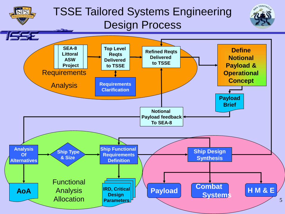
TSSE Tailored Systems Engineering
Design Process
Synthesis
Top Level
Reqts
Delivered
to TSSE
SEA-8
Littoral
ASW
Project
Notional
Payload feedback
To SEA-8
Define
Notional
Payload &
Operational
Concept
Payload
Brief
Requirements
Clarification
Refined Reqts
Delivered
to TSSE
Ship Type
& Size
IRD, Critical
Design
Parameters
Ship Functional
Requirements
Definition
Ship Design
Synthesis
PayloadCombat
SystemsH M & E
Requirements
Analysis
Functional
Analysis
AllocationAoA
Analysis
Of
Alternatives

6
Top Level Requirements
• Deploy, retrieve, and regenerate large UUVs semi-clandestinely
• Sensor assets required to provide Pd 0.8 across contested OA (6,700 NM2)
within 10 days
• Provide logistic support necessary to sustain SoS for 30 days
• Communicate on the following circuits:
High Band Width Air/Space Line of Sight (LOS) LOS Data
LOS Voice OTH Data
OTH Voice SATCOM
Underwater Data
• Launch, recover, and control a 7,000 lb UAV
• Deploy box-launcher weapons and torpedoes for enemy engagement
Deploy
Prepare system components Deliver system components Sustain system components

7
Notional Payload and Operational
Concept
70
nm
100 nm
10 nm
10
nm

8
Top Level Analysis of Alternatives
(AoA)
• Conducted from Aug-Sep using notional payload architecture and SEA-8 scenario
• Competing Architectures:
-- LCAC size craft (single and wave) -- Mid-size ship
-- LCS Module (single and wave)
• Selection Criteria:
-- Capability (30) -- Deployability (20) -- Survivability (20)
-- Endurance (10) -- Flexibility (10) -- Technical Risk (5)
-- Cost (5)

9
Top Level AoA Results
0
10
20
30
40
50
60
70
80
901 LCAC
7 LCAC Wave
Mid-SizeAmphib
1 LCS
3 LCS
10
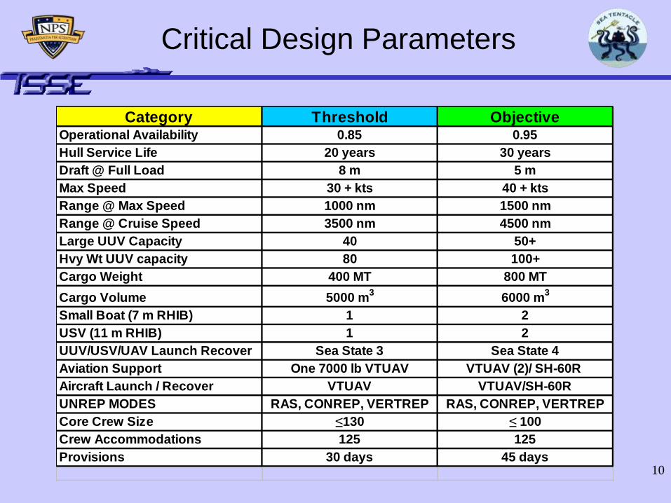
Category Threshold ObjectiveOperational Availability 0.85 0.95
Hull Service Life 20 years 30 years
Draft @ Full Load 8 m 5 m
Max Speed 30 + kts 40 + kts
Range @ Max Speed 1000 nm 1500 nm
Range @ Cruise Speed 3500 nm 4500 nm
Large UUV Capacity 40 50+
Hvy Wt UUV capacity 80 100+
Cargo Weight 400 MT 800 MT
Cargo Volume 5000 m3
6000 m3
Small Boat (7 m RHIB) 1 2
USV (11 m RHIB) 1 2
UUV/USV/UAV Launch Recover Sea State 3 Sea State 4
Aviation Support One 7000 lb VTUAV VTUAV (2)/ SH-60R
Aircraft Launch / Recover VTUAV VTUAV/SH-60R
UNREP MODES RAS, CONREP, VERTREP RAS, CONREP, VERTREP
Core Crew Size ≤130 ≤ 100
Crew Accommodations 125 125
Provisions 30 days 45 days
Critical Design Parameters

11
Agenda
Introduction and Overall Design Process
• Payload and Operational Concept– Components
– Launch, Deployment, and Recovery
– Handling Systems
– Payload Modeling
• Combat Systems
• Hull, Mechanical, and Electrical (HM&E)
• Summary

12
Notional Architecture
Challenge Response
Contested air spaceCovert insertion and recovery,
200nm standoff range
30 day sustained
operations
Centralized hub replenishment
and recovery
Time and Space:
100 nm2 in 72 hrs
6700 nm2 in 10 days
Single launch cycle followed by
ongoing service cycles

13
10 nm X 10 nm Network HubArchitecture Refinement with TSSE/SEA-8 Collaboration
• 1 Large UUV (*Sea Predator)
• 1 Sled equipped with deployable RF buoy, acoustic modem, docking transducers, coupling two 21” diameter shapes
• 6 Light Weight UUVs – four for power, two for sensor processing and communications control
• 16 man-portable sensor and wire deployment vehicles
* Sea Predator, David DeMartino, NAVSEA Panama City
TSSE Design

14
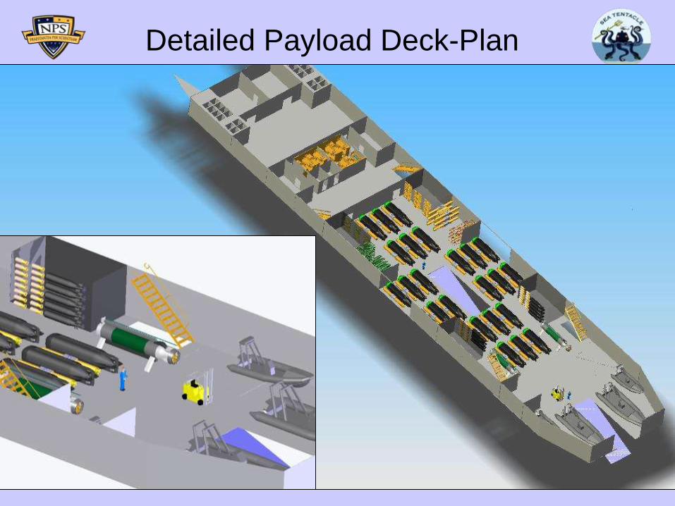
Payload Deck
Port and Starboard Side Doors
Amidships and Stern Ramps

15
Handling Systems
• X-Y-Z Overhead Hoist Array and Deck-rail Storage System
– Longitudinal overhead monorail along centerline
– Transverse overhead rail pairs
– Reconfigurable two tier shelves anchored into deck rails provide
secure stowage
– Port and Starboard amidships rail extensions provide over the
side lift capabilities
– Amidships ramp cradle handles up to Large UUV’s
– Stern ramp variable geometry cradle for larger capacity launch
and recovery
SCOUVO NSWC Carderock Innovation Center

16
Notional Architecture

17
2025 Notional Sensor Coverage
ASSUMPTIONS:
-1 nm Detection Radii
-Sensor Spacing:
4 nodes at 5nm
8 nodes at 4nm
4 nodes at 2nm
1 center node
10 nm
10 nm
18
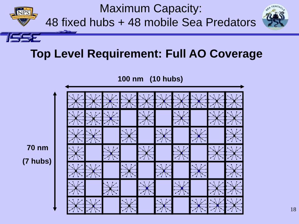
Maximum Capacity:
48 fixed hubs + 48 mobile Sea Predators
70 nm
(7 hubs)
100 nm (10 hubs)
Top Level Requirement: Full AO Coverage

19
72 Hour Single Hub Deployment
Mission Range: 1000nm
0 12 24 36 48 60 72
Full-Up-Around
Initialize System
LWV Docking
Sensor Deployment
Sea Predator Transit
Sea Predator Launch
Sea Tentacle Transit
Loitering at 1,000nm from the Harbor Gate AO,
Sea Tentacle receives urgent tasking:
800nm sprint at 35 knots (23 hrs)
Single launch event: Predator with external
docking sled (1 hr)
200nm transit at 5 knots (40 hrs)
Sensor deployment vehicle max range of
5nm at 5 knots (2 hrs)
LWV’s launch and dock with sled (2 hrs)
Power up, system optimization and self
test, communications check-in (4 hrs)
20
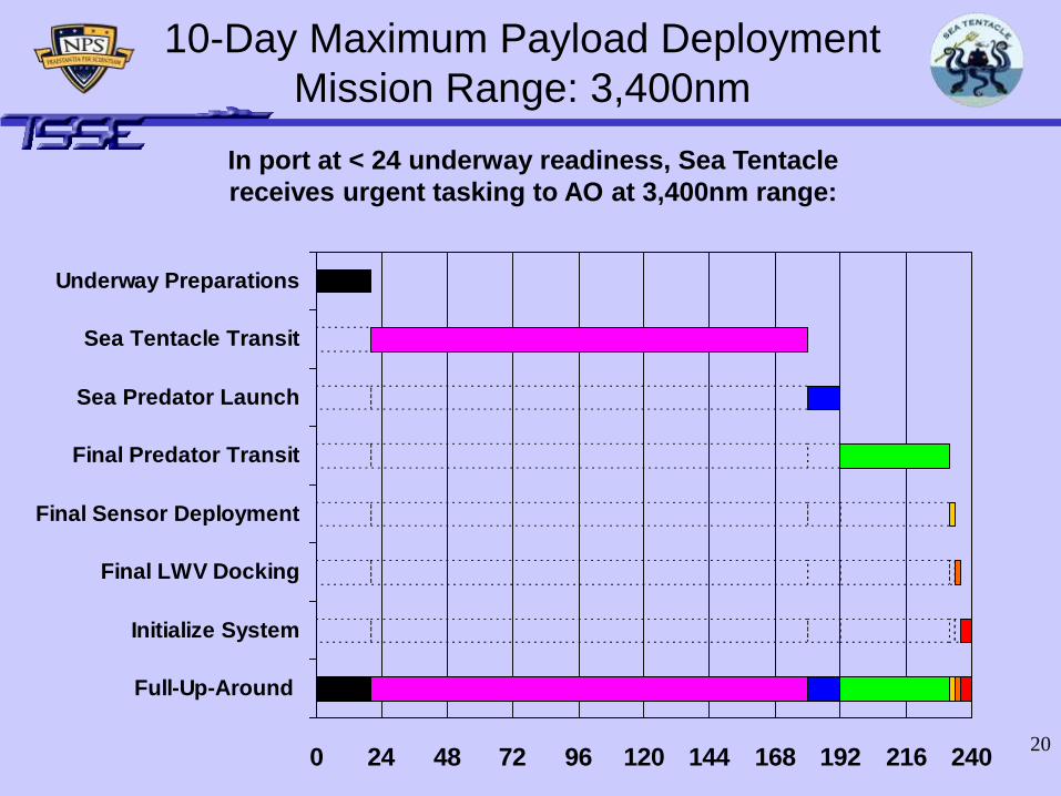
10-Day Maximum Payload Deployment
Mission Range: 3,400nm
0 24 48 72 96 120 144 168 192 216 240
Full-Up-Around
Initialize System
Final LWV Docking
Final Sensor Deployment
Final Predator Transit
Sea Predator Launch
Sea Tentacle Transit
Underway Preparations
In port at < 24 underway readiness, Sea Tentacle
receives urgent tasking to AO at 3,400nm range:

21
UUV Network Applications
• Perimeter defense of Sea Base and high value transit lanes
• Core ASW and MIW capabilities providing offensive and defensive early warning envisioned by Sea Shield
• Wide area battle-space preparation and intelligence gathering capabilities for time critical Sea Strike

22
Mission Payload
Baseline Operational Unit Count
Sea
Predator
(Large UUV)
AN/WLD-1
(Large UUV)
11m RHIB
(USV equipped)7m RHIB SH-60R VTUAV
48 2 2 2 2 2
23
Detailed Payload Deck-Plan

24
Payload Top Level Requirements
Deploy, retrieve, and regenerate large UUVs semi-clandestinely
Sensor assets required to provide Pd 0.8 across contested OA (6,700 NM2)
within 10 days
Provide logistic support necessary to sustain SoS for 30 days
• Communicate on the following circuits:
High Band Width Air/Space Line of Sight (LOS) LOS Data
LOS Voice OTH Data
OTH Voice SATCOM
Underwater Data
• Launch, recover, and control a 7,000 lb UAV
• Deploy box-launcher weapons and torpedoes for enemy engagement
Deploy
Prepare system components Deliver system components Sustain system components
25
Agenda
Introduction and Overall Design Process
Payload and Operational Concept
• Combat Systems– Derived Requirements
• Weapons Deployment
• Communications
– Design Philosophy
– ICMS Architecture
– Component Selection• Layered Defense
• Radio Frequency Systems
– Radar Cross Section Analysis
– Summary
• Hull, Mechanical, and Electrical (HM&E)
• Summary

26
Threat Matrix
D – Detection SK – Soft Kill HK – Hard Kill
HK* - Anti-ship ESSM requires software upgrade
SENSORS WEAPONS
Threat AMRFS TISS EW Suite ISMD/A ASROC ESSM SSM Millenium Gun
ASCM D D D - SK HK HK
Aircraft D D D HK HK
Ship D D D D HK * HK HK
Submarine D HK
Small boats D D D D HK HK
Mines D HK
Shore Fire D D HK HK

27
Defense in Depth
ESSM
SSM
Millennium Gun
VLA
1.5 nm 2.0 nm 3 nm 50+ nm 80+ nm
SURFACE VESSEL / LITTORAL TARGET
SEA SKIMMING MISSILE
ASCM
AIRCRAFT
7 nm
Mid Defense LayerInner Defense Layer
5 nm

28
External Communications
RF External Communications
• The ship will be fully interoperable with the following systems:
– CEC
– Joint Planning Network
– Joint Data Network
– GCCS-M
– SIPRNET
– NIPRNET
• The following frequency ranges / data rates will be supported:
- UHF SATCOM 512 – 4.5 Mbps
- SHF SATCOM 1.544 Mbps (T-1) – 45 Mbps (T-3)
- UHF LOS 200 kbps

29
Integrated Combat
Management System
ORIENT &
DECIDE
AC
T
OB
SE
RV
E

30
Open Architecture Acquisition Way Ahead Slide 20 10/27/2005
ConfigurationTENTACLE ICMS BL 1.0
Engagement Schedule
RV Action Schedule
Engineering Schedule
Weapon Action
RV Action
Engineering ActionMission
Assessment
Threat Assessment
(including identity)
Assigned Missions
Action Plans
Plan
C2 Order, Schedule & Event
TacticalPicture
5.0 Mission Exec.1.0 Search & Detect
Multi -Sensor Correlated Track
2.0 Data/InformationServices (DIS)
System Track
Composite/Collaborative Track
INTEL -Generated Track
Track Repository
11 33 6622 88
9.0 Force Planning/Coordination (FP/C)
Joint BFOrders
CommandersEstimate
Course OfAction
BFOrders
66
3.0 Planning, Assessment & Decision (PAD)
22 44 66 88 22 33 55 66
4.0 Weapon/AssetServices (W/AS)
22 33 44
99
ALL
7.0 Common Services (CS) Display Time
NAV DX/DR
Databases Environment
33
8.0 Training (TR)
TrainingAction Plan
TrainingSchedule
TrainingEvent
Scenario
Simulator Stimulator
66
44 88
Data Links SatCom
DDS Radios
6.0 EXCOMMComms
Service ActionNetwork Schedule Message Event
2211
99
3 44
66
66
88
55
SensorControl
Radar Sensor SuiteIFF
Dual Band Radar Acoustic Sensor Suite
LMRSSensor System
Towed ArraySensor System
Bow ArraySensor System
Acoustic InterceptSensor (AIS)
ES/Intel Suite ES
ComponentEO/IR Suite
FLIR/LRF Imagery Integrated Bridge
Damage D&A
Engineering Control
TLAM, LASM
ASROC (VLA)
ESSM, SM -2 MR
LRLAP
40 MM
NULKA,Giant,Chaff
Towed TorpedoCountermeasures
VTUAV
MH - 60R
Missile Control
LAM Missile Control
CIGS Control
Torpedo WpnControl AGS Control
Decoy Control
VTUAV Vehicle Control
Helicopter Control
Engagement Schedule
RV Action Schedule
Engineering Schedule
Weapon Action
RV Action
Engineering Action
Engagement Schedule
RV Action Schedule
Engineering Schedule
Weapon Action
RV Action
Engineering ActionMission
Assessment
Threat Assessment
(including identity)
Assigned Missions
Action Plans
Plan
C2 Order, Schedule & Event
TacticalPicture
Mission Assessment
Threat Assessment
(including identity)
Assigned Missions
Action Plans
Plan
C2 Order, Schedule & Event
TacticalPicture
5.0 Mission Exec.1.0 Search & Detect
Multi -Sensor Correlated Track
2.0 Data/InformationServices (DIS)
System Track
Composite/Collaborative Track
INTEL -Generated Track
Track Repository
Multi -Sensor Correlated Track
2.0 Data/InformationServices (DIS)
System Track
Composite/Collaborative Track
INTEL -Generated Track
Track Repository
1111 3333 66662222 8888
9.0 Force Planning/Coordination (FP/C)
Joint BFOrders
CommandersEstimate
Course OfAction
BFOrders
6666
3.0 Planning, Assessment & Decision (PAD)
22 44 66 88 22 33 55 66
4.0 Weapon/AssetServices (W/AS)
22 33 44
99
ALL
7.0 Common Services (CS) Display Time
NAV DX/DR
Databases Environment
3333
8.0 Training (TR)
TrainingAction Plan
TrainingSchedule
TrainingEvent
Scenario
Simulator Stimulator
66
4444 8888
Data Links SatCom
DDS Radios
6.0 EXCOMMComms
Service ActionNetwork Schedule Message Event
2211
99
3 44
66
66
88
5555
SensorControl
Radar Sensor SuiteIFF
Dual Band Radar
Radar Sensor SuiteIFF
Dual Band Radar Acoustic Sensor Suite
LMRSSensor System
Towed ArraySensor System
Bow ArraySensor System
Acoustic InterceptSensor (AIS)
Acoustic Sensor Suite
LMRSSensor System
Bow ArraySensor System
Acoustic InterceptSensor (AIS)
ES/Intel Suite ES
Component
ES/Intel Suite ES
ComponentEO/IR Suite
FLIR/LRF EO/IR Suite
TISS.IRST Imagery Integrated Bridge
Damage D&A
Engineering Control
ASROC (VLA)
ESSM - ASM-
LRLAP
Millenium Gun
NULKA,Giant,Chaff
VTUAV
MH - 60R
Missile Control
Control
CIGS Control
Torpedo WpnControl AGS Control
Decoy Control
VTUAV Vehicle Control
Helicopter Control
ICMS Open Architecture Design

31
Sea TENTACLE
Net-Centric ASW-MIW
Operating Characteristics:
•Net-Centric
•Collaborative
•Distributed Functionality
•Strong HSI Focus
Mission Areas:
•Littoral ASW/MIW
•SUW (Maritime Surveillance)
•AAW
Mission Areas

32
Inner Defense Layer AoA
0.00
0.50
1.00
1.50
2.00
2.50
3.00
3.50
4.00
Overall MOP
Sea Ram CIWS 1B Millennium
Gun
Goal
Keeper
Systems
Inner Defense Layer Trade Study
Footprint (Physical, RCS)
Responsiveness
Air Threat Capability
Surface Threat Capability
Range
Operational Availability
Personnel
Modularity
Selected System: Millennium Gun- Range (air): 3.5 nm
- Range (cruise missiles) : 1.08 nm
- Range (sea-skimming missiles): 0.8 nm
- Firing Rate: 1,000 rounds/min
- 152 sub-projectiles per round
Design Requirements Weight Sea Ram CIWS 1B Millennium Gun Goal Keeper
Modularity 0.15 1.00 5.00 5.00 2.00
Personnel 0.10 4.00 2.00 3.00 2.00
Operational Availability 0.15 4.50 4.50 4.00 4.00
Range 0.10 5.00 5.00 3.00 3.50
Surface Threat Capability 0.15 1.00 2.50 5.00 0.00
Air Threat Capability 0.10 5.00 4.50 3.50 4.00
Responsiveness 0.10 5.00 4.00 3.50 4.00
Footprint (Physical, RCS) 0.15 2.00 2.00 4.00 2.00
Totals 1.00 0.64 0.73 0.80 0.51

33
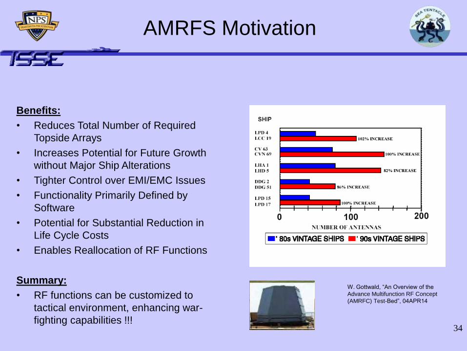
Advanced Multifunction RF System
(AMRFS) Capabilities
Multi-functional:
• Communications
– Satellite Communications
– Line-of-Sight Communications
• Electronic Attack (EA)
– Noise Jamming
– Deceptive Jamming
• Electronic Surveillance (ES)
• Radar
– Surface Navigation Radar
– Volume Search
• Reduced Maintenance
– Array & Subsystem Calibration, Characterization, and Diagnostics
Source: Raytheon DBR
34
Benefits:
• Reduces Total Number of Required
Topside Arrays
• Increases Potential for Future Growth
without Major Ship Alterations
• Tighter Control over EMI/EMC Issues
• Functionality Primarily Defined by
Software
• Potential for Substantial Reduction in
Life Cycle Costs
• Enables Reallocation of RF Functions
Summary:
• RF functions can be customized to
tactical environment, enhancing war-
fighting capabilities !!!
W. Gottwald, “An Overview of the
Advance Multifunction RF Concept
(AMRFC) Test-Bed”, 04APR14
AMRFS Motivation

35
• For our design RCS estimation, we used two
techniques:
– Empirical Method (Skolnik)
– Physical Optics Method (POFACETS Software)
Radar Cross Section
(RCS) Estimation

36
Empirical Method of RCS Estimation
• Skolnik (1980) suggested a formula to estimate the median RCS
of a ship based on its displacement and the frequency of
operation of a given seeker:
• For our design, with a displacement of around 7000 LT and a
frequency of operation of 0.3 GHz:
• This approximation varies with the angle. 13 dB (for broadside)
are added and 8 dB (for minima) are subtracted.
2
3
kT GHzm1644 D f
2
Sea-Tentacle 16 42 dBsm m677
Sea-Tentacle34 dBsm 55 dBsm

37
• POFACETS is a RCS tool developed by
Dr. Jenn of the ECE Dept. of NPS.
• It is based on the Physical Optics Method.
• Ship Parameters used by POFACETS
were generated with RHINO software.
RCS Results using a PEC material model at a frequency of 0.3 GHz
Physical Optics Method
of RCS Estimation

38
Composite material ship yields a median
RCS of approximately 5dBsm
Steel ship yields a median
RCS of approximately 25dBsm
RCS as a Function of
Material Selection
Composite vs. PEC (Steel)

39
RCS Results using a Steel Ship model vs.
Seeker frequency at a 090/270 TA
RCS: Beam target angle for
steel ship.
Steel material selection renders
lowest RCS at frequencies:
• 2.3 GHz
• 4.1 GHz
• 7.2 GHz
RCS as a Function of
Seeker Frequency

40
• Empirical and simulation results for RCS are similiar.
• POFACETS results facilitated material considerations.
• RCS Comparisons are comparable between 2004 and 2005 TSSE designs.
• RCS Analysis (unclassified) and does not take into account AMRFS RF emissions.
RCS Conclusions
AC
CE
SS
-2
00
4T
EN
TA
CL
E -
20
05

41
Deploy, retrieve, and regenerate large UUVs semi-clandestinely
Sensor assets required to provide Pd 0.8 across contested OA (6,700 NM2)
within 10 days
Provide logistic support necessary to sustain SoS for 30 days
Communicate on the following circuits:
- High Band Width Air/Space Line of Sight (LOS) - LOS Data
- LOS Voice - OTH Data
- OTH Voice - SATCOM
- Underwater Data
Launch, recover, and control a 7,000 lb UAV
Deploy box-launcher weapons and torpedoes for enemy engagement
Deploy
Prepare system components Deliver system components Sustain system components
Combat Systems Top-Level
Requirements

42
ICMS Summary
• Integrated Design philosophy can
summed up as “no stovepipes.”
• Open Architecture Focus
Embraces Technology Growth.
• Multi-mission capability supports
dynamic mission requirements.

43
Agenda
Introduction and Overall Design Process
Payload and Operational Concept
Combat Systems
• Hull, Mechanical, and Electrical (HM&E)
– Initial Hull Selection AoA
– Hydrostatics, Damaged Stability, Structures
– Resistance, Propulsion, Electrical
– Seakeeping
• Summary

44
Hull Selection
• Systems
Engineering
Waterfall Model
used
• Applied up to
component
development
stage
Component
Development
User Needs &
Top Level
Requirements
System
Architecture &
Requirements
System Design
Change &
Feedback
Change &
Feedback
Change &
Feedback
Operations &
Maintenance,
Deactivation
Integration &
Verification
Installation &
Validation
Change &
Feedback
Change &
Feedback
Change &
Feedback

45
Hull Type Comparison
• Long endurance at low speeds
• Ruggedness, simplicity, and durability
• Tolerance to growth in weight and
displacement
• Existing infrastructure of yards, docks, and
support facilities is designed for monohulls
• Low cost
Monohull

46
Hull Type Comparison
• Reduced powering requirements at high
speeds
• Reduced draft
• Increased deck area and growth margin
• Increased seakeeping
• Increased powering requirements at low
speeds because of large wetted surface area
Trimaran

47
Hull Type Comparison
In addition to Trimaran;
• Good stability after dropping off all the
payload
• Advantage of using the space between
demihulls as launching / recovering stations
(semi-covert operations)
• Best speed for high weight / cargo load
Catamaran

48
Mission Bay Comparison
SCOUVO – Surface Combat Optimized for Unmanned Vehicle Operations – NSWC Carderock
Monohull: 16 ISO containers
Catamaran: 21 ISO containers
Trimaran: 7 ISO containers
ISO: 6 x 2.5 x 2.5m

49
Hull Type AoA
0.00
0.50
1.00
1.50
2.00
2.50
3.00
3.50
4.00
4.50
5.00
Monohull Catamaran Trimaran
Footprint (RCS)
Stability
Sea Keeping
Grow th Margin
Deck Area
Draft
Cost
Risk
Endurance at high speed
Endurance at low speed
Requirement Weight Weighted Weighted Weighted
Endurance at low speed 0.06 5.00 0.30 4.00 0.24 3.50 0.21
Endurance at high speed 0.07 3.00 0.21 4.50 0.32 5.00 0.35
Risk 0.08 5.00 0.40 4.00 0.32 3.00 0.24
Cost 0.10 5.00 0.50 4.00 0.40 3.50 0.35
Draft 0.10 3.50 0.35 4.50 0.45 5.00 0.50
Deck Area 0.16 3.00 0.48 5.00 0.80 4.00 0.64
Growth Margin 0.08 4.00 0.32 5.00 0.40 5.00 0.40
Sea Keeping 0.10 4.00 0.40 5.00 0.50 5.00 0.50
Stability 0.15 4.00 0.60 4.50 0.68 5.00 0.75
Footprint (RCS) 0.10 4.00 0.40 5.00 0.50 4.00 0.40
Total 1.00 0.79 0.92 0.87
Monohull Catamaran Trimaran

50
Catamaran was selected
Hull Form
51
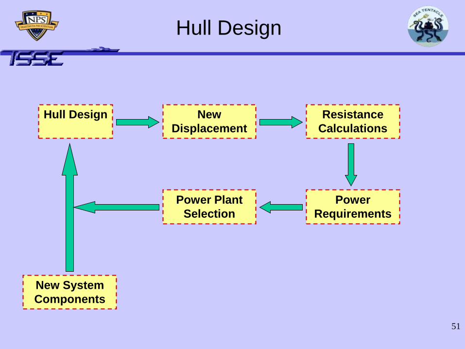
Hull Design
Hull Design New
Displacement
Resistance
Calculations
Power
Requirements
Power Plant
Selection
New System
Components
52
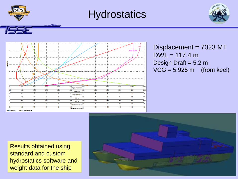
Hydrostatics
Displacement = 7023 MT
DWL = 117.4 mDesign Draft = 5.2 m
VCG = 5.925 m (from keel)
Results obtained using
standard and custom
hydrostatics software and
weight data for the ship

53
Intact Stability
Positive Righting Arm up to 85o

54
Damaged Stability
Can survive in
case of loss of
one demi-hull
Can survive
with all engine
rooms flooded

55
Structural Strength
Max. Bending Stress = 154.4 MPa
at hogging condition at midship
section
Steel was selected

56
Ship Characteristics
Light Ship = 4504 MT
Loaded Displacement = 7023 MT
LOA = 120 m
LWL = 117.4 m
Beam = 25 m
Design Draft = 5.2 m
Metacentric Height = 16.05 m
Design Trim = 0.1o to Bow
Design Heel = 0.51o to Port

57
Power Estimation from Resistance
Calculations
Shaft Power (kW)
0
10000
20000
30000
40000
50000
60000
70000
80000
90000
100000
0 5 10 15 20 25 30 35 40 45 50
Speed (kts)
kW
NavCad
AutoPower
AverageSpeed Shaft Power (kW)
0 0
5 403.02
10 2645.84
15 7528.65
20 15419.89
25 26510.43
30 40627.94
35 56712.14
40 72155.12
45 91213.34
1LM 2500+ 1LM 6000 2LM 2500+’s
1LM 2500+1LM6000 2LM 2500+’s+1LM6000

58
Gas Turbine Analysis Snapshot
0
0.5
1
1.5
2
2.5
3
3.5
4
4.5
1 2
Alternatives
AoA of Gas Turbines
Thermal Efficiency
Weight
Volume
SFC
Weighting
Factor
Alternative – 11-LM6000
2 LM2500+
Alternative – 22 MT30
1 LM2500+
Specific Fuel
Consumption 0.4 4 4
Volume 0.3 5 2
Weight 0.2 4 5
Thermal Efficiency 0.1 5 5
Total Score 1 4.4 3.7

59
Summary of Chosen Propulsion
Systems
• Propulsion Plant: Gas Turbines
• Specifically: 2 LM2500+
1 LM6000
1 Allison 501-K34
60
Summary of Chosen Propulsion
Systems
• Electric drive
• 2 Bird-Johnson AWJ-21
water jets
• 2 bow thrusters

61
Endurance Load vs Speed (for 4500 NM)
0
1000
2000
3000
4000
5000
6000
7000
8000
9000
10000
0 10 20 30 40 50
Speed (Kts)
En
du
ran
ce L
oad
(M
T)
Range vs Speed
0
1000
2000
3000
4000
5000
6000
0 10 20 30 40 50
Speed (Kts)
Ma
x.
Ra
ng
e (
NM
)Range Calculations
Speed Max. Range Speed Endurance Load
(kts) (NM) (kts) for 4500 NM (MT)
5 1831.094 5 4367
10 2468.7828 10 3239
15 5439.71939 15 1470
20 5462.01332 20 1464
25 2212.61414 25 3614
30 1754.36321 30 4558
35 1045.41607 35 7649
40 921.880044 40 8674

62
Endurance and Speed
• Transiting Speed of 20 kts gives Range of 5,400 nm
Max Speed 40 kts
• Sprint Speed of 35 kts gives Range of 1,000 nm

63
Summary of Chosen Motor System
• Motor alternatives:
– Conventional COTS motor
– Superconducting DC Homopolar motor
– High Temperature Superconducting AC
motor
• High Temperature Superconducting
Synchronous AC Motor Selected

64
Integrated Power System
• IPS is an AC/DC hybrid zonal
• Total capacity is 103 MW
• 93 MW required for 40 knots, 6MW for ship service loads, 4 MW reserve
• Gas turbines produce 3 phase 13.8 kVolt AC
• All ship service loads distributed via 1000 volts DC

65
Port HTS
Motor
Stbd HTS
Motor
LM2500+ LM2500+
LM6000Allison
13.8 K volts
3 Φ
1000 volts
DC
Ship Service Loads
Bidirectional AC/AC
converter (w/ galvanic
isolation)
13.8 K volts
3 Φ
Sea Tentacle Electric Plant

66
Zonal Distribution
Superstructure
Forward
Forward E.R.Handling Aft E.R.
Propulsion

67
Seakeeping Results
• Evaluate response in regular seas; varying
ship speeds and headings.
• Within linear theory, evaluate response in
random seas using regular wave results.
• Assume long-crested, fully developed seas.
• Set limiting values of the response and
calculate the operating envelope.
• Adjust design parameters to achieve an
acceptable operating envelope.

68
Speed-Polar Plot
Head
Following
Forward quartering
Beam
Aft quartering

69
Limiting Values
• Assume the following limiting values for the responses:
– Significant single amplitudes:• Ship roll: 5 deg.
• Ship pitch: 3 deg.
• Absolute vertical velocity at ramp: 2 m/sec– Depends on ramp (x,y) location
– Expected number of events per hour:• Wetness (relative vertical motion hits zero)
events at ramp: 30– Depends on ramp (x,y,z) location

70
Vertical Velocity

71
Wetness Events

72
Operating Envelope
Operations can be sustained
Operations are unsafe

73
Design Selection
Ramp height at 2 m above calm waterline provides
adequate operability region
1 m
2 m

74
Sea State Effects
2 m clearance provides adequate operating envelope
even for elevated sea states

75
Operability Index – Aft Ramp
76
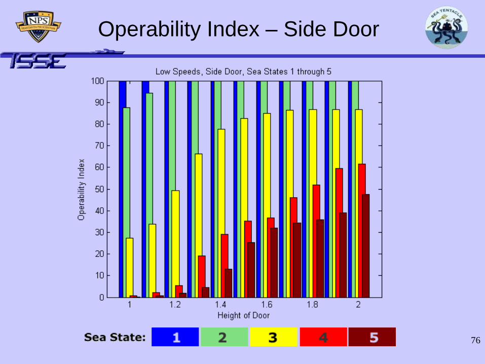
Operability Index – Side Door

77
Wave Generation
V=15 Kts
V=20 Kts
Kelvin wave pattern calculated
using a 3-D panel method

78
Agenda
Introduction and Overall Design Process
Payload and Operational Concept
Combat Systems
Hull, Mechanical, and Electrical (HM&E)
• Summary– Manning
– Cost
– Geographical Transit Ranges
– Requirements Summary
– Conclusion

79
Manning
• Reduced manning possible concepts
studied on DD(X) and TAK-E(X):
– Human Centered Design and Reasoning
Systems
– Reliability and Condition Based Maintenance
vs. Preventative Maintenance System (PMS)
– Automated Damage Control
– Reduced Watch Stations
– Self Service Laundry
– Innovative Messing
80
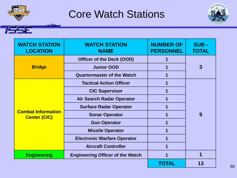
Core Watch Stations
WATCH STATION
LOCATION
WATCH STATION
NAME
NUMBER OF
PERSONNEL
SUB -
TOTAL
Bridge
Officer of the Deck (OOD) 1
3Junior OOD 1
Quartermaster of the Watch 1
Combat Information
Center (CIC)
Tactical Action Officer 1
9
CIC Supervisor 1
Air Search Radar Operator 1
Surface Radar Operator 1
Sonar Operator 1
Gun Operator 1
Missile Operator 1
Electronic Warfare Operator 1
Aircraft Controller 1
Engineering Engineering Officer of the Watch 1 1
TOTAL 13

81
Procurement Cost Estimation
Process
• Two methods were used to estimate cost:– Top-down method using data from the
Congressional Budget Office (CBO), Visibility and Management of Operating and Support Costs (VAMOSC), and others
– Bottom-up method using detailed weight-based Cost Estimating Relationships (CERs), labor costs, and specialized equipment costs
– The bottom-up method produced results that were less than 10% lower than the top-down method
– For brevity, only the top-down method is detailed on the following slides
82
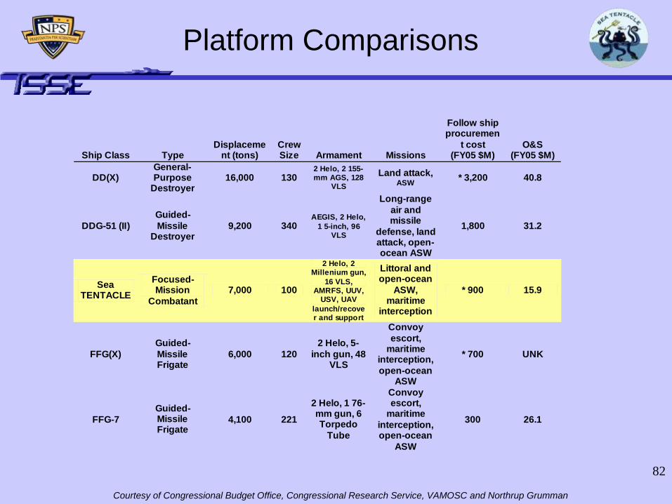
Ship Class Type Displaceme
nt (tons) Crew Size Armament Missions
Follow ship procuremen
t cost (FY05 $M)
O&S (FY05 $M)
DD(X) General-Purpose
Destroyer 16,000 130
2 Helo, 2 155-mm AGS, 128
VLS
Land attack, ASW
* 3,200 40.8
DDG-51 (II)
Guided-
Missile Destroyer
9,200 340 AEGIS, 2 Helo,
1 5-inch, 96 VLS
Long-range
air and missile
defense, land attack, open-ocean ASW
1,800 31.2
Sea TENTACLE
Focused-Mission
Combatant
7,000 100
2 Helo, 2 Millenium gun,
16 VLS, AMRFS, UUV,
USV, UAV
launch/recover and support
Littoral and open-ocean
ASW, maritime
interception
* 900 15.9
FFG(X)
Guided-
Missile Frigate
6,000 120
2 Helo, 5-
inch gun, 48 VLS
Convoy
escort, maritime
interception,
open-ocean ASW
* 700 UNK
FFG-7
Guided-Missile Frigate
4,100 221
2 Helo, 1 76-mm gun, 6 Torpedo
Tube
Convoy escort,
maritime
interception, open-ocean
ASW
300 26.1
Courtesy of Congressional Budget Office, Congressional Research Service, VAMOSC and Northrup Grumman
Platform Comparisons

83
Figures courtesy of Congressional Budget Office assuming 3% inflation rate
Lead Ship Cost Estimate
(in millions of 2005 dollars)
Estimated
Cost
Primary Basis of
Estimate
Detail Design 200 FFG(X)/LCS
Analogies
Infrastructure Upgrade 250 Catamaran Hull
Construction
Production Costs: Basic Construction 990 FFG(X) Analogy
VLS 16 FFG(X) Analogy Advanced Combat Systems
Suite 200
AMFRS
Catamaran Construction 100
Total Lead Ship Cost ~1,750
84
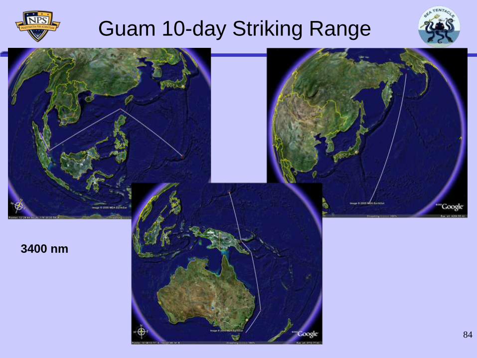
Guam 10-day Striking Range
3400 nm

85
Diego Garcia 10-day Striking Range
3400 nm

86
Sasebo 3-day Striking Range
1000 nm
87
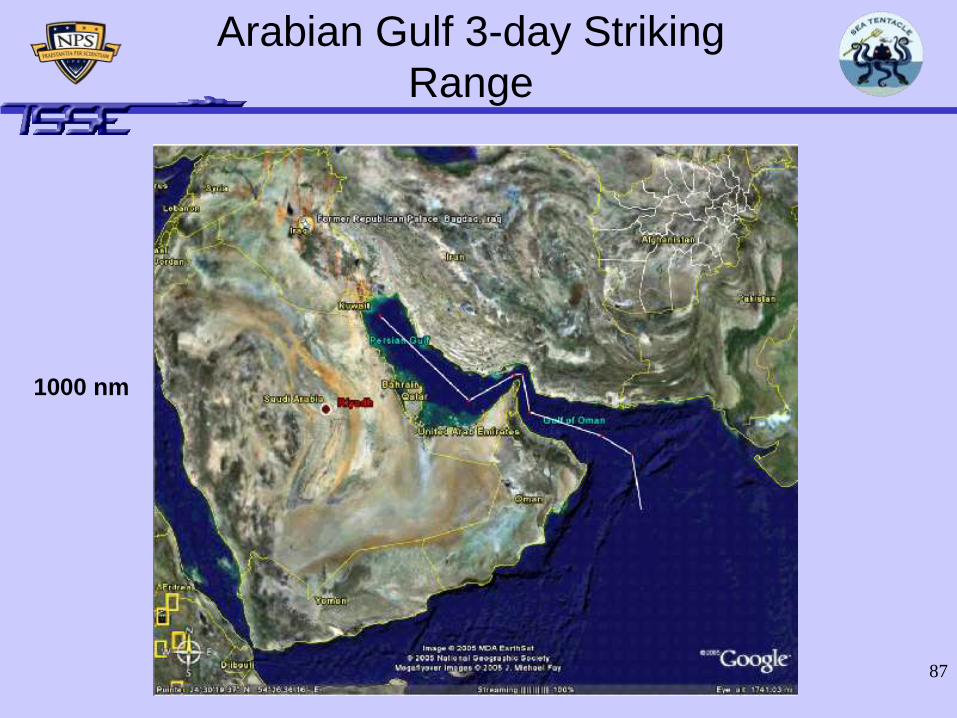
Arabian Gulf 3-day Striking
Range
1000 nm
88
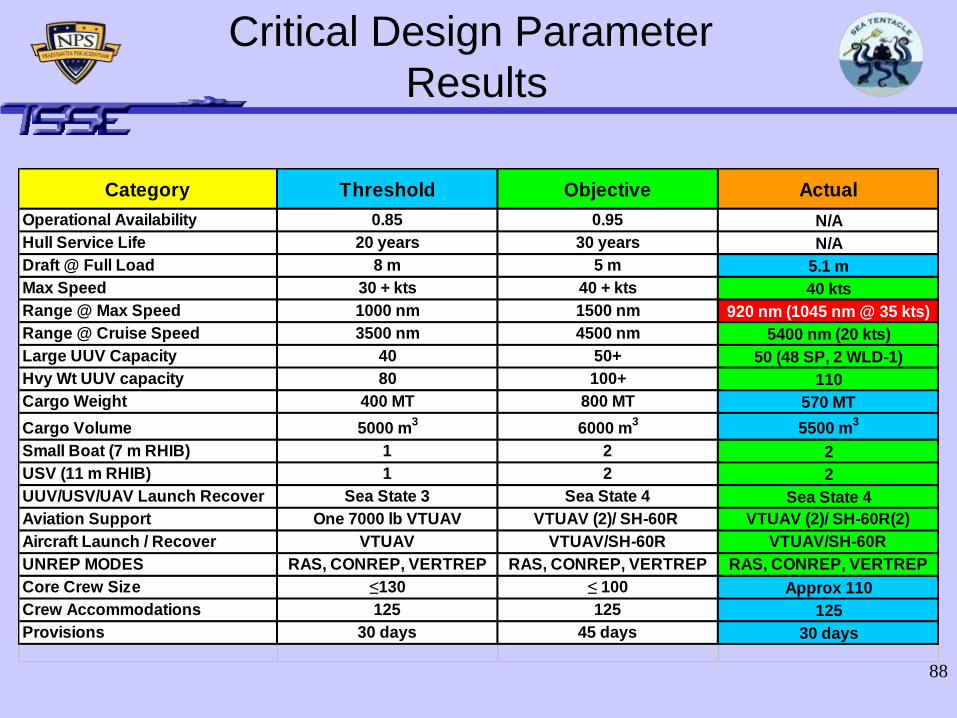
Critical Design Parameter
Results
Category Threshold Objective Actual
Operational Availability 0.85 0.95 N/A
Hull Service Life 20 years 30 years N/A
Draft @ Full Load 8 m 5 m 5.1 m
Max Speed 30 + kts 40 + kts 40 kts
Range @ Max Speed 1000 nm 1500 nm 920 nm (1045 nm @ 35 kts)
Range @ Cruise Speed 3500 nm 4500 nm 5400 nm (20 kts)
Large UUV Capacity 40 50+ 50 (48 SP, 2 WLD-1)
Hvy Wt UUV capacity 80 100+ 110
Cargo Weight 400 MT 800 MT 570 MT
Cargo Volume 5000 m3
6000 m3
5500 m3
Small Boat (7 m RHIB) 1 2 2
USV (11 m RHIB) 1 2 2
UUV/USV/UAV Launch Recover Sea State 3 Sea State 4 Sea State 4
Aviation Support One 7000 lb VTUAV VTUAV (2)/ SH-60R VTUAV (2)/ SH-60R(2)
Aircraft Launch / Recover VTUAV VTUAV/SH-60R VTUAV/SH-60R
UNREP MODES RAS, CONREP, VERTREP RAS, CONREP, VERTREP RAS, CONREP, VERTREP
Core Crew Size ≤130 ≤ 100 Approx 110
Crew Accommodations 125 125 125
Provisions 30 days 45 days 30 days

89
Top Level Requirements Revisited
Deploy, retrieve, and regenerate large UUVs semi-clandestinely
Sensor assets required to provide Pd 0.8 across contested OA (6,700 NM2)
within 10 days
Provide logistic support necessary to sustain SoS for 30 days
Communicate on the following circuits:
- High Band Width Air/Space Line of Sight (LOS) - LOS Data
- LOS Voice - OTH Data
- OTH Voice - SATCOM
- Underwater Data
Launch, recover, and control a 7,000 lb UAV
Deploy box-launcher weapons and torpedoes for enemy engagement
Deploy
Prepare system components Deliver system components Sustain system components

90
Conclusions
• Employs a large, well designed, and flexible
Payload configuration
• Combat Systems offer a robust mix of Offensive
and Defensive capabilities that can conduct
simultaneous ASW, SUW, & AAW operations
• HM&E design delivers high speed & high power
in a unique and efficient manner
Sea TENTACLE is the platform of
choice for Littoral ASW in 2025