Tracer® AdaptiView™ Display for CenTraVac™ Water-cooled ...
92
Tracer® AdaptiView™ Display for CenTraVac™ Water-cooled Chillers User Guide March 2020 CTV-SVU01G-EN SAFETY WARNING Only qualified personnel should install and service the equipment. The installation, starting up, and servicing of heating, ventilating, and air-conditioning equipment can be hazardous and requires specific knowledge and training. Improperly installed, adjusted or altered equipment by an unqualified person could result in death or serious injury. When working on the equipment, observe all precautions in the literature and on the tags, stickers, and labels that are attached to the equipment. X39641071060
Transcript of Tracer® AdaptiView™ Display for CenTraVac™ Water-cooled ...
Tracer® AdaptiView™ Display for
CenTraVac™ Water-cooled Chillers
User Guide
March 2020 CTV-SVU01G-EN
SAFETY WARNINGOnly qualified personnel should install and service the equipment. The installation, starting up, and servicing of heating, ventilating, and air-conditioning equipment can be hazardous and requires specific knowledge and training. Improperly installed, adjusted or altered equipment by an unqualified person could result in death or serious injury. When working on the equipment, observe all precautions in the literature and on the tags, stickers, and labels that are attached to the equipment.
X39641071060
©2020Trane CTV-SVU01G-EN
Warnings, Cautions, and Notices
Safety advisories appear throughout this manual as required.Your personal safety and the properoperation of this machine depend upon the strict observance of these precautions.
The three types of advisories are defined as follows:
WARNING Indicates a potentially hazardous situation which, if not avoided, could result indeath or serious injury.
CAUTIONsIndicates a potentially hazardous situation which, if not avoided, could result inminor or moderate injury. It could also be used to alert against unsafe practices.
NOTICEIndicates a situation that could result in equipment or property-damage onlyaccidents.
WARNING
Proper Field Wiring and Grounding Required!
Failure to follow code could result in death or serious injury. All field wiring MUST beperformed by qualified personnel. Improperly installed and grounded field wiring poses FIREand ELECTROCUTION hazards.To avoid these hazards, you MUST follow requirements for fieldwiring installation and grounding as described in NEC and your local/state electrical codes.Failure to follow code could result in death or serious injury.
WARNING
Personal Protective Equipment (PPE) Required!
Failure to wear proper PPE for the job being undertaken could result in death or serious injury.Technicians, in order to protect themselves from potential electrical, mechanical, and chemicalhazards, MUST follow precautions in this manual and on the tags, stickers, and labels, as wellas the instructions below:
• Before installing/servicing this unit, technicians MUST put on all PPE required for the work
being undertaken (Examples; cut resistant gloves/sleeves, butyl gloves, safety glasses, hard
hat/bump cap, fall protection, electrical PPE and arc flash clothing). ALWAYS refer to
appropriate Safety Data Sheets (SDS) and OSHA guidelines for proper PPE.
• When working with or around hazardous chemicals, ALWAYS refer to the appropriate SDS
and OSHA/GHS (Global Harmonized System of Classification and Labeling of Chemicals)
guidelines for information on allowable personal exposure levels, proper respiratory
protection and handling instructions.
• If there is a risk of energized electrical contact, arc, or flash, technicians MUST put on all PPE
in accordance with OSHA, NFPA 70E, or other country-specific requirements for arc flash
protection, PRIOR to servicing the unit. NEVER PERFORM ANY SWITCHING,
DISCONNECTING, OR VOLTAGETESTING WITHOUT PROPER ELECTRICAL PPE AND ARC
FLASH CLOTHING. ENSURE ELECTRICAL METERSAND EQUIPMENTARE PROPERLY RATED
FOR INTENDED VOLTAGE.

CTV-SVU01G-EN 3
WWAARRNNIINNGGFFoollllooww EEHHSS PPoolliicciieess!!FFaaiilluurree ttoo ffoollllooww iinnssttrruuccttiioonnss bbeellooww ccoouulldd rreessuulltt iinn ddeeaatthh oorr sseerriioouuss iinnjjuurryy..
•• AAllll TTrraannee ppeerrssoonnnneell mmuusstt ffoollllooww tthhee ccoommppaannyy’’ss EEnnvviirroonnmmeennttaall,, HHeeaalltthh aanndd SSaaffeettyy((EEHHSS)) ppoolliicciieess wwhheenn ppeerrffoorrmmiinngg wwoorrkk ssuucchh aass hhoott wwoorrkk,, eelleeccttrriiccaall,, ffaallll pprrootteeccttiioonn,,lloocckkoouutt//ttaaggoouutt,, rreeffrriiggeerraanntt hhaannddlliinngg,, eettcc.. WWhheerree llooccaall rreegguullaattiioonnss aarree mmoorreessttrriinnggeenntt tthhaann tthheessee ppoolliicciieess,, tthhoossee rreegguullaattiioonnss ssuuppeerrsseeddee tthheessee ppoolliicciieess..
•• NNoonn--TTrraannee ppeerrssoonnnneell sshhoouulldd aallwwaayyss ffoollllooww llooccaall rreegguullaattiioonnss..
CopyrightThis document and the information in it are the property of Trane, and may not be used orreproduced in whole or in part without written permission. Trane reserves the right to revise thispublication at any time, and to make changes to its content without obligation to notify anyperson of such revision or change.
TrademarksAll trademarks referenced in this document are the trademarks of their respective owners.
Factory TrainingFactory training is available through Trane University™ to help you learn more about theoperation and maintenance of your equipment. To learn about available training opportunitiescontact Trane University™.
Online: www.trane.com/traneuniversity
Phone: 855-803-3563
Email: [email protected]
Revision History• Added LLID Binding section.
• Updated “Evaporator settings and status points (Simplex)”, “Condenser settings and statuspoints (Simplex)”, “Motor settings and status points (Simplex)”, “Condenser data” and“Evaporator data” tables in Appendix A — Data for CenTraVac Simplex Chillers.
4 CTV-SVU01G-EN
Product Overview. . . . . . . . . . . . . . . . . . . . . . . . . . . . . . . . . . . . . . . . . . . . . . . . . . . . . . . . . . . . . . 7Equipment Description . . . . . . . . . . . . . . . . . . . . . . . . . . . . . . . . . . . . . . . . . . . . . . . . . . . . . . . 7
Touchscreen Guidelines . . . . . . . . . . . . . . . . . . . . . . . . . . . . . . . . . . . . . . . . . . . . . . . . . . . . . . 8
Related Information . . . . . . . . . . . . . . . . . . . . . . . . . . . . . . . . . . . . . . . . . . . . . . . . . . . . . . . . . 8
Screen Overview . . . . . . . . . . . . . . . . . . . . . . . . . . . . . . . . . . . . . . . . . . . . . . . . . . . . . . . . . . . . 8Chiller Status Area . . . . . . . . . . . . . . . . . . . . . . . . . . . . . . . . . . . . . . . . . . . . . . . . . . . . . . . 9Main Display Area/Home Screen . . . . . . . . . . . . . . . . . . . . . . . . . . . . . . . . . . . . . . . . . 10Main Display Area/Screen Saver. . . . . . . . . . . . . . . . . . . . . . . . . . . . . . . . . . . . . . . . . . 14Component Screens. . . . . . . . . . . . . . . . . . . . . . . . . . . . . . . . . . . . . . . . . . . . . . . . . . . . . 14Main Menu Area . . . . . . . . . . . . . . . . . . . . . . . . . . . . . . . . . . . . . . . . . . . . . . . . . . . . . . . . 17
Stopping/Restarting Chiller Operation . . . . . . . . . . . . . . . . . . . . . . . . . . . . . . . . . . . . . . . . 18Stopping the Chiller . . . . . . . . . . . . . . . . . . . . . . . . . . . . . . . . . . . . . . . . . . . . . . . . . . . . . . . . . 18
Restarting the Chiller . . . . . . . . . . . . . . . . . . . . . . . . . . . . . . . . . . . . . . . . . . . . . . . . . . . . . . . . 19
Alarms. . . . . . . . . . . . . . . . . . . . . . . . . . . . . . . . . . . . . . . . . . . . . . . . . . . . . . . . . . . . . . . . . . . . . . . . 20The Alarms Screen. . . . . . . . . . . . . . . . . . . . . . . . . . . . . . . . . . . . . . . . . . . . . . . . . . . . . . . . . . 20
Alarm Icons. . . . . . . . . . . . . . . . . . . . . . . . . . . . . . . . . . . . . . . . . . . . . . . . . . . . . . . . . . . . . 21Active and Historic Alarm Categories . . . . . . . . . . . . . . . . . . . . . . . . . . . . . . . . . . . . . 21Sorting Alarms. . . . . . . . . . . . . . . . . . . . . . . . . . . . . . . . . . . . . . . . . . . . . . . . . . . . . . . . . . 21
Resetting Alarms . . . . . . . . . . . . . . . . . . . . . . . . . . . . . . . . . . . . . . . . . . . . . . . . . . . . . . . . . . . 22
Additional Alarm Indicators. . . . . . . . . . . . . . . . . . . . . . . . . . . . . . . . . . . . . . . . . . . . . . . . . . 22
Reports . . . . . . . . . . . . . . . . . . . . . . . . . . . . . . . . . . . . . . . . . . . . . . . . . . . . . . . . . . . . . . . . . . . . . . . 23The Reports Screen . . . . . . . . . . . . . . . . . . . . . . . . . . . . . . . . . . . . . . . . . . . . . . . . . . . . . . . . . 23
Viewing the Log Sheet . . . . . . . . . . . . . . . . . . . . . . . . . . . . . . . . . . . . . . . . . . . . . . . . . . . . . . 23
Viewing the ASHRAE Chiller Log . . . . . . . . . . . . . . . . . . . . . . . . . . . . . . . . . . . . . . . . . . . . . 24
Creating and Viewing a Custom Report . . . . . . . . . . . . . . . . . . . . . . . . . . . . . . . . . . . . . . . 24
Editing a Custom Report. . . . . . . . . . . . . . . . . . . . . . . . . . . . . . . . . . . . . . . . . . . . . . . . . . . . . 25
About this Chiller . . . . . . . . . . . . . . . . . . . . . . . . . . . . . . . . . . . . . . . . . . . . . . . . . . . . . . . . . . . 26
Viewing Chiller Operating Modes . . . . . . . . . . . . . . . . . . . . . . . . . . . . . . . . . . . . . . . . . . . . 26Simplex Chillers. . . . . . . . . . . . . . . . . . . . . . . . . . . . . . . . . . . . . . . . . . . . . . . . . . . . . . . . . 26Duplex Chillers. . . . . . . . . . . . . . . . . . . . . . . . . . . . . . . . . . . . . . . . . . . . . . . . . . . . . . . . . . 28Purge Operating Modes . . . . . . . . . . . . . . . . . . . . . . . . . . . . . . . . . . . . . . . . . . . . . . . . . 31
Data Graphs . . . . . . . . . . . . . . . . . . . . . . . . . . . . . . . . . . . . . . . . . . . . . . . . . . . . . . . . . . . . . . . . . . 32The Data Graphs Screen. . . . . . . . . . . . . . . . . . . . . . . . . . . . . . . . . . . . . . . . . . . . . . . . . . . . . 32
Viewing Data Graphs. . . . . . . . . . . . . . . . . . . . . . . . . . . . . . . . . . . . . . . . . . . . . . . . . . . . . . . . 33
Changing the Scales on Data Graphs . . . . . . . . . . . . . . . . . . . . . . . . . . . . . . . . . . . . . . . . . 34
Creating Custom Data Graphs . . . . . . . . . . . . . . . . . . . . . . . . . . . . . . . . . . . . . . . . . . . . . . . 35Creating a Custom Data Graph From a Default Data Graph. . . . . . . . . . . . . . . . . . 35
Table of Contents

CTV-SVU01G-EN 5
Creating a Custom Data Graph With No Previously Defined Data GraphPoints . . . . . . . . . . . . . . . . . . . . . . . . . . . . . . . . . . . . . . . . . . . . . . . . . . . . . . . . . . . . . . . . . . 37Editing Custom Data Graphs . . . . . . . . . . . . . . . . . . . . . . . . . . . . . . . . . . . . . . . . . . . . . 37
Deleting a Custom Data Graph . . . . . . . . . . . . . . . . . . . . . . . . . . . . . . . . . . . . . . . . . . . . . . . 38
Equipment Settings. . . . . . . . . . . . . . . . . . . . . . . . . . . . . . . . . . . . . . . . . . . . . . . . . . . . . . . . . . . 39The Settings Screen. . . . . . . . . . . . . . . . . . . . . . . . . . . . . . . . . . . . . . . . . . . . . . . . . . . . . . . . . 39
Viewing and Changing Equipment Settings . . . . . . . . . . . . . . . . . . . . . . . . . . . . . . . . . . . 39
Chiller Settings . . . . . . . . . . . . . . . . . . . . . . . . . . . . . . . . . . . . . . . . . . . . . . . . . . . . . . . . . . . . . 42
Service Settings . . . . . . . . . . . . . . . . . . . . . . . . . . . . . . . . . . . . . . . . . . . . . . . . . . . . . . . . . . . . 43
Setpoint Sources . . . . . . . . . . . . . . . . . . . . . . . . . . . . . . . . . . . . . . . . . . . . . . . . . . . . . . . . . . . 43Setpoint Source Arbitration . . . . . . . . . . . . . . . . . . . . . . . . . . . . . . . . . . . . . . . . . . . . . . 43
Changing the Setpoint Source . . . . . . . . . . . . . . . . . . . . . . . . . . . . . . . . . . . . . . . . . . . . . . . 44Using the Setpoint Source Button in the Chiller Status Area. . . . . . . . . . . . . . . . . 44From the Setpoint Source Button on the Chiller Settings Screen. . . . . . . . . . . . . 44From an Arbitrated Setpoint Screen . . . . . . . . . . . . . . . . . . . . . . . . . . . . . . . . . . . . . . 45
Feature Settings . . . . . . . . . . . . . . . . . . . . . . . . . . . . . . . . . . . . . . . . . . . . . . . . . . . . . . . . . . . . 46
Chilled Water Reset . . . . . . . . . . . . . . . . . . . . . . . . . . . . . . . . . . . . . . . . . . . . . . . . . . . . . . . . . 46
Purge Settings. . . . . . . . . . . . . . . . . . . . . . . . . . . . . . . . . . . . . . . . . . . . . . . . . . . . . . . . . . . . . . 47
Manual Control Settings. . . . . . . . . . . . . . . . . . . . . . . . . . . . . . . . . . . . . . . . . . . . . . . . . . . . . 47
Changing a Manual Control Setting . . . . . . . . . . . . . . . . . . . . . . . . . . . . . . . . . . . . . . . . . . 49
Display Settings . . . . . . . . . . . . . . . . . . . . . . . . . . . . . . . . . . . . . . . . . . . . . . . . . . . . . . . . . . . . . . 51Settings Screen. . . . . . . . . . . . . . . . . . . . . . . . . . . . . . . . . . . . . . . . . . . . . . . . . . . . . . . . . . . . . 51
Viewing and Changing Display Preferences . . . . . . . . . . . . . . . . . . . . . . . . . . . . . . . . . . . 51
Viewing and Changing the Language Preference . . . . . . . . . . . . . . . . . . . . . . . . . . . . . . 54
Viewing and Changing Date and Time Preferences . . . . . . . . . . . . . . . . . . . . . . . . . . . . 56
Clean Touchscreen. . . . . . . . . . . . . . . . . . . . . . . . . . . . . . . . . . . . . . . . . . . . . . . . . . . . . . . . . . 57
Security Settings . . . . . . . . . . . . . . . . . . . . . . . . . . . . . . . . . . . . . . . . . . . . . . . . . . . . . . . . . . . . . 58Settings Screen. . . . . . . . . . . . . . . . . . . . . . . . . . . . . . . . . . . . . . . . . . . . . . . . . . . . . . . . . . . . . 58
Disabling Security . . . . . . . . . . . . . . . . . . . . . . . . . . . . . . . . . . . . . . . . . . . . . . . . . . . . . . . . . . 58
Enabling Security . . . . . . . . . . . . . . . . . . . . . . . . . . . . . . . . . . . . . . . . . . . . . . . . . . . . . . . . . . . 59
Logging In . . . . . . . . . . . . . . . . . . . . . . . . . . . . . . . . . . . . . . . . . . . . . . . . . . . . . . . . . . . . . . . . . 59
Logging Out . . . . . . . . . . . . . . . . . . . . . . . . . . . . . . . . . . . . . . . . . . . . . . . . . . . . . . . . . . . . . . . . 61
LLID Binding . . . . . . . . . . . . . . . . . . . . . . . . . . . . . . . . . . . . . . . . . . . . . . . . . . . . . . . . . . . . . . . 61
Troubleshooting . . . . . . . . . . . . . . . . . . . . . . . . . . . . . . . . . . . . . . . . . . . . . . . . . . . . . . . . . . . . . . 62
Appendix A: Data for CenTraVac Simplex Chillers . . . . . . . . . . . . . . . . . . . . . . . . . . . . 63Component Screen Data. . . . . . . . . . . . . . . . . . . . . . . . . . . . . . . . . . . . . . . . . . . . . . . . . . . . . 63
TTaabbllee ooff CCoonntteennttss

6 CTV-SVU01G-EN
Reports . . . . . . . . . . . . . . . . . . . . . . . . . . . . . . . . . . . . . . . . . . . . . . . . . . . . . . . . . . . . . . . . . . . . 65Log Sheet . . . . . . . . . . . . . . . . . . . . . . . . . . . . . . . . . . . . . . . . . . . . . . . . . . . . . . . . . . . . . . 65ASHRAE Chiller Log . . . . . . . . . . . . . . . . . . . . . . . . . . . . . . . . . . . . . . . . . . . . . . . . . . . . . 67Items Available to Include in Custom Reports. . . . . . . . . . . . . . . . . . . . . . . . . . . . . . 69
Data Graph Data Points. . . . . . . . . . . . . . . . . . . . . . . . . . . . . . . . . . . . . . . . . . . . . . . . . . . . . . 72Data Points Used in Default Data Graphs . . . . . . . . . . . . . . . . . . . . . . . . . . . . . . . . . . 72Data Points in Custom Data Graphs . . . . . . . . . . . . . . . . . . . . . . . . . . . . . . . . . . . . . . . 75
Appendix B: Data for CenTraVac Duplex Chillers . . . . . . . . . . . . . . . . . . . . . . . . . . . . . 77Component Screen Data. . . . . . . . . . . . . . . . . . . . . . . . . . . . . . . . . . . . . . . . . . . . . . . . . . . . . 77
Reports . . . . . . . . . . . . . . . . . . . . . . . . . . . . . . . . . . . . . . . . . . . . . . . . . . . . . . . . . . . . . . . . . . . . 78Log Sheet . . . . . . . . . . . . . . . . . . . . . . . . . . . . . . . . . . . . . . . . . . . . . . . . . . . . . . . . . . . . . . 79ASHRAE Chiller Log . . . . . . . . . . . . . . . . . . . . . . . . . . . . . . . . . . . . . . . . . . . . . . . . . . . . . 80Items Available to Include in Custom Reports. . . . . . . . . . . . . . . . . . . . . . . . . . . . . . 82Data Graph Data Points . . . . . . . . . . . . . . . . . . . . . . . . . . . . . . . . . . . . . . . . . . . . . . . . . . 83
Data Points Used in Default Data Graphs. . . . . . . . . . . . . . . . . . . . . . . . . . . . . . . . . . . . . . 83
Data Points in Custom Data Graphs . . . . . . . . . . . . . . . . . . . . . . . . . . . . . . . . . . . . . . . . . . 86
TTaabbllee ooff CCoonntteennttss
CTV-SVU01G-EN 7
Product OverviewThe Tracer® AdaptiView™ display provides a means for viewing data and for making operationalchanges on the following types of chillers:
• Simplex (single compressor) CenTraVac™ chiller models
• Duplex™ (dual compressor) CenTraVac™ chiller models
The purpose of this guide is to assist you in using the Tracer® AdaptiView™ display. This guidedescribes how to access the screens and the types of information that appear on the screens.
Equipment DescriptionThe basic equipment features of the Tracer® AdaptiView™ display are described here.
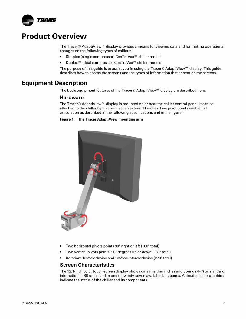
HHaarrddwwaarreeThe Tracer® AdaptiView™ display is mounted on or near the chiller control panel. It can beattached to the chiller by an arm that can extend 11 inches. Five pivot points enable fullarticulation as described in the following specifications and in the figure:
Figure 1. The Tracer AdaptiView mounting arm
• Two horizontal pivots points 90º right or left (180º total)
• Two vertical pivots points: 90º degrees up or down (180º total)
• Rotation: 135º clockwise and 135º counterclockwise (270º total)
SSccrreeeenn CChhaarraacctteerriissttiiccssThe 12.1-inch color touch-screen display shows data in either inches and pounds (I-P) or standardinternational (SI) units, and in one of twenty-seven available languages. Animated color graphicsindicate the status of the chiller and its components.
8 CTV-SVU01G-EN
DDCC PPoowweerrThe Tracer® AdaptiView™ display receives 24 Vdc power through its power cable. The Tracer®UC800 controller must be powered on.
CCoommmmuunniiccaattiioonnA separate ethernet cable provides communication between the Tracer® AdaptiView™ displayand the Tracer® UC800 controller. Alarms are communicated immediately upon detection.
Touchscreen GuidelinesThe touch screen registers the downward pressure of a touch. However, touching with increasedpressure has no effect.
Use your fingers to operate the touch screen. Do NOT use a pen or pencil point, or any othersharp or pointed object that might scratch the screen surface.
If you apply and hold pressure at more than one point, the touch screen registers only the firsttouch. For example, if you press a finger on an area of the screen that is not touch sensitive,pressing a sensitive area with another finger will not register.
Holding on to the screen with your hand can cause unintended navigation, such as from thumbor palm pressure.
Related InformationAdditional information on CenTraVac™ chillers with Tracer® AdaptiView™ control can be foundin these documents:
• CVHE-SVX02*-EN (Installation, Operation, and Maintenance: CVHE, CVHF, and CVHGWater-Cooled CenTraVac Chillers with Tracer AdaptiView Control )
• CDHF-SVX01*-EN (Installation, Operation, and Maintenance: CDHF and CDHGWater-CooledCenTraVac Chillers with Tracer AdaptiView Control )
• CVHH-SVX001*-EN (Installation, Operation, and Maintenance: CVHHWater-CooledCenTraVac Chillers with Tracer AdaptiView Control )
• CDHH-SVX001*-EN (Installation, Operation, and Maintenance: CDHHWater-CooledCenTraVac Chillers with Tracer AdaptiView Control)
• PRGF-SVX001*-EN (Installation, Operation, and Maintenance: EarthWise Purge System withTracer AdaptiView Control for Water-cooled CenTraVac Chillers with R-123 Refrigerant)
• PRGG-SVX001*-EN (Installation, Operation, and Maintenance: Purge System with TracerAdaptiView Control for Water-cooled CenTraVac Chillers with R-514A Refrigerant)
• CTV-SVD03*-EN (Diagnostics Manual: Diagnostic Descriptions, Troubleshooting Tables, andControl Component Overview for Water-cooled CenTraVac Chillers with Tracer AdaptiViewControl)
• CTV-SVP02*-EN (Programming Guide: Tracer TU Service Tool for Water-cooled CenTraVacChillers with Tracer AdaptiView Control)
• TTU-SVN01*-EN (Getting Started Guide: Tracer TU Service Tool)
Screen OverviewThe touch-sensitive areas of the Tracer® AdaptiView™ display screen are described in detail inthis section.
PPrroodduucctt OOvveerrvviieeww
CTV-SVU01G-EN 9
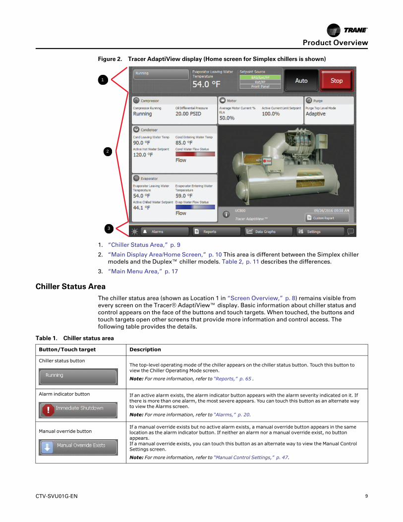
Figure 2. Tracer AdaptiView display (Home screen for Simplex chillers is shown)
1
2
3
1. “Chiller Status Area,” p. 9
2. “Main Display Area/Home Screen,” p. 10 This area is different between the Simplex chillermodels and the Duplex™ chiller models. Table 2, p. 11 describes the differences.
3. “Main Menu Area,” p. 17
Chiller Status AreaThe chiller status area (shown as Location 1 in “Screen Overview,” p. 8) remains visible fromevery screen on the Tracer® AdaptiView™ display. Basic information about chiller status andcontrol appears on the face of the buttons and touch targets. When touched, the buttons andtouch targets open other screens that provide more information and control access. Thefollowing table provides the details.
Table 1. Chiller status area
Button/Touch target Description
Chiller status buttonThe top-level operating mode of the chiller appears on the chiller status button. Touch this button toview the Chiller Operating Mode screen.
Note: For more information, refer to “Reports,” p. 65 .
Alarm indicator button If an active alarm exists, the alarm indicator button appears with the alarm severity indicated on it. Ifthere is more than one alarm, the most severe appears. You can touch this button as an alternate wayto view the Alarms screen.
Note: For more information, refer to “Alarms,” p. 20.
Manual override buttonIf a manual override exists but no active alarm exists, a manual override button appears in the samelocation as the alarm indicator button. If neither an alarm nor a manual override exist, no buttonappears.If a manual override exists, you can touch this button as an alternate way to view the Manual ControlSettings screen.
Note: For more information, refer to “Manual Control Settings,” p. 47.
PPrroodduucctt OOvveerrvviieeww
10 CTV-SVU01G-EN
Table 1. Chiller status area (continued)
Button/Touch target Description
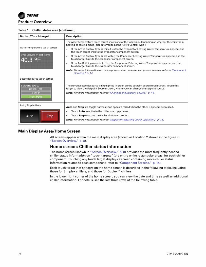
Water temperature touch target
The water temperature touch target shows one of the following, depending on whether the chiller is inheating or cooling mode (also referred to as the Active Control Type):
• If the Active Control Type is chilled water, the Evaporator Leaving Water Temperature appears andthe touch target links to the evaporator component screen.
• If the Active Control Type is hot water, the Condenser Leaving Water Temperature appears and thetouch target links to the condenser component screen.
• If the Ice Building mode is Active, the Evaporator Entering Water Temperature appears and thetouch target links to the evaporator component screen.
Note: For more information on the evaporator and condenser component screens, refer to “ComponentScreens,” p. 14.
Setpoint source touch target
The current setpoint source is highlighted in green on the setpoint source touch target. Touch thistarget to view the Setpoint Source screen, where you can change the setpoint source.
Note: For more information, refer to “Changing the Setpoint Source,” p. 44 .
Auto/Stop buttonsAuto and Stop are toggle buttons: One appears raised when the other is appears depressed.
• Touch Auto to activate the chiller startup process.
• Touch Stop to active the chiller shutdown process.
Note: For more information, refer to “Stopping/Restarting Chiller Operation,” p. 18.
Main Display Area/Home ScreenAll screens appear within the main display area (shown as Location 2 shown in the figure in“Screen Overview,” p. 8).
HHoommee ssccrreeeenn:: CChhiilllleerr ssttaattuuss iinnffoorrmmaattiioonnThe home screen (shown in “Screen Overview,” p. 8) provides the most frequently neededchiller status information on “touch targets” (the entire white rectangular areas) for each chillercomponent. Touching any touch target displays a screen containing more chiller statusinformation related to each component (refer to “Component Screens,” p. 14).
Each touch target that appears on the home screen is described in the following table, includingthose for Simplex chillers, and those for Duplex™ chillers.
In the lower right corner of the home screen, you can view the date and time as well as additionalchiller information. For details, see the last three rows of the following table.
PPrroodduucctt OOvveerrvviieeww
CTV-SVU01G-EN 11
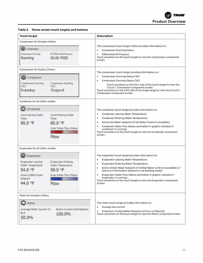
Table 2. Home screen touch targets and buttons
Touch target Description
Compressor for Simplex chillers
This compressor touch target chiller provides information on:
• Compressor Running Status
• Differential Oil PressureTouch anywhere on the touch target to view the Compressor componentscreen.
Compressor for Duplex ChillersThis compressor touch target provides information on:
• Compressor Running Status Ckt1
• Compressor Running Status Ckt2
Touch anywhere on the Ckt1 side of the touch target to view theCircuit 1 Compressor component screen.
Touch anywhere on the Ckt2 side of the tough target to view the Circuit 2Compressor component screen.
Condenser for all chiller models
This condenser touch target provides information on:
• Condenser Leaving Water Temperature
• Condenser Entering Water Temperature
• Active Hot Water Setpoint (if Hot Water Control is available)
• Condenser Water Flow Status (animation in graphic indicates ifcondenser is running)
Touch anywhere on the touch target to view the Condenser componentscreen.
Evaporator for all chiller models
The evaporator touch target provides information on:
• Evaporator Leaving Water Temperature
• Evaporator Entering Water Temperature
• Active Chilled Water Setpoint (if Chilled Water Control is available) orActive Ice Termination Setpoint in Ice Building mode)
• Evaporator Water Flow Status (animation in graphic indicates ifevaporator is running)
Touch anywhere on the touch target to view the Evaporator componentscreen.
Motor for Simplex chillers
The motor touch target provides information on:
• Average line current
• Frequency (if adjustable-frequency drive is configured)Touch anywhere on the touch target to view the Motor component screen.
PPrroodduucctt OOvveerrvviieeww
12 CTV-SVU01G-EN
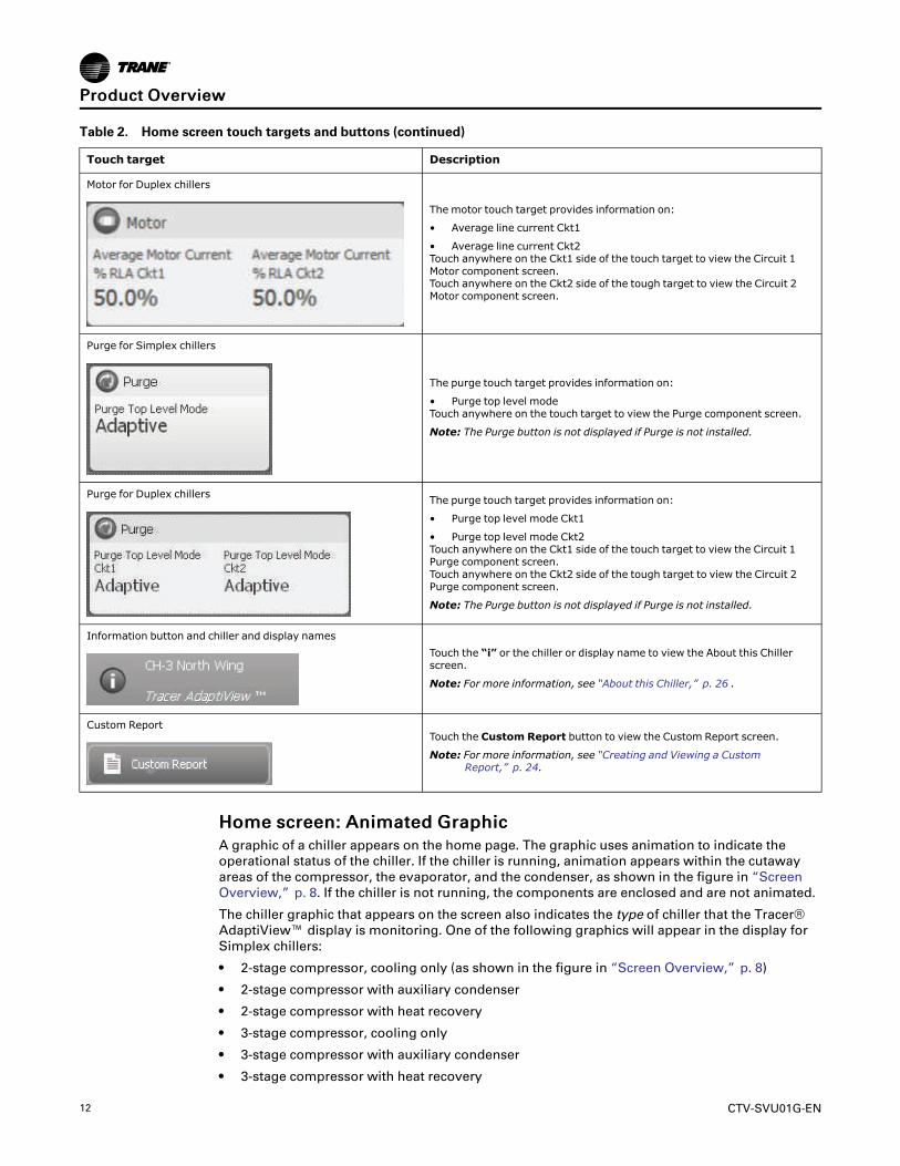
Table 2. Home screen touch targets and buttons (continued)
Touch target Description
Motor for Duplex chillers
The motor touch target provides information on:
• Average line current Ckt1
• Average line current Ckt2Touch anywhere on the Ckt1 side of the touch target to view the Circuit 1Motor component screen.Touch anywhere on the Ckt2 side of the tough target to view the Circuit 2Motor component screen.
Purge for Simplex chillers
The purge touch target provides information on:
• Purge top level modeTouch anywhere on the touch target to view the Purge component screen.
Note: The Purge button is not displayed if Purge is not installed.
Purge for Duplex chillers The purge touch target provides information on:
• Purge top level mode Ckt1
• Purge top level mode Ckt2Touch anywhere on the Ckt1 side of the touch target to view the Circuit 1Purge component screen.Touch anywhere on the Ckt2 side of the tough target to view the Circuit 2Purge component screen.
Note: The Purge button is not displayed if Purge is not installed.
Information button and chiller and display namesTouch the “i” or the chiller or display name to view the About this Chillerscreen.
Note: For more information, see “About this Chiller,” p. 26 .
Custom ReportTouch the Custom Report button to view the Custom Report screen.
Note: For more information, see “Creating and Viewing a CustomReport,” p. 24.
HHoommee ssccrreeeenn:: AAnniimmaatteedd GGrraapphhiiccA graphic of a chiller appears on the home page. The graphic uses animation to indicate theoperational status of the chiller. If the chiller is running, animation appears within the cutawayareas of the compressor, the evaporator, and the condenser, as shown in the figure in “ScreenOverview,” p. 8. If the chiller is not running, the components are enclosed and are not animated.
The chiller graphic that appears on the screen also indicates the type of chiller that the Tracer®AdaptiView™ display is monitoring. One of the following graphics will appear in the display forSimplex chillers:
• 2-stage compressor, cooling only (as shown in the figure in “Screen Overview,” p. 8)
• 2-stage compressor with auxiliary condenser
• 2-stage compressor with heat recovery
• 3-stage compressor, cooling only
• 3-stage compressor with auxiliary condenser
• 3-stage compressor with heat recovery
PPrroodduucctt OOvveerrvviieeww

CTV-SVU01G-EN 13
One of the following graphics will appear on the display for Duplex™ chillers:
• 2–stage compressor
• 3–stage compressor
PPrroodduucctt OOvveerrvviieeww

14 CTV-SVU01G-EN
Main Display Area/Screen SaverAfter 30 minutes of inactivity, the screen dims and a screen saver appears in the main displayarea as shown in the following figure. The screen saver also appears if you touch the animatedgraphic on the home screen. Alternately, if you touch the screen saver, the home screen appears.
Figure 3. Screen saver
Component ScreensEach chiller component has a touch target, accessible from the home screen, that is illustrated in“Screen Overview,” p. 8 (main display area/home screen) and described in “Main Display Area/Home Screen,” p. 10.
SSiimmpplleexx CChhiilllleerrssIf you touch anywhere on a component touch target, a screen appears containing data that isrelated to that component (see the example in the following figure). You can use the shortcutbuttons at the top of each of the component screens to view the other components screens.
“Appendix A: Data for CenTraVac Simplex Chillers,” p. 63 lists the settings and status points thatare accessible from each of the component screens. The chiller configuration determines whichof the settings and status points appear.
PPrroodduucctt OOvveerrvviieeww

CTV-SVU01G-EN 15
Figure 4. Component screen example for Simplex chillers
1
2
1. Data Graph shortcut button
2. Component screen shortcut buttons
DDuupplleexx CChhiilllleerrssEach component has a separate screen for circuit 1 and circuit 2.
• If you touch anywhere on an evaporator or condenser component touch target, a screenappears containing data related to circuit 1 of that component (refer to the following figure).
• If you touch in the circuit 1 data area of a compressor, motor, or purge component touchtarget, a screen appears containing data related to circuit 1 of that component. If you touch inthe circuit 2 data area of a compressor, motor, or purge component touch target, a screenappears containing data related to circuit 2 of that component.
Circuit 1 and Circuit 2 buttons at the bottom of each component screen (see Location 4 in thefollowing figure) allow you to toggle between circuit 1 and circuit 2 component screens.
You can use the shortcut buttons at the top of each of the component screens (see Location 2 inthe preceding figure) to view the other components screens. If you are viewing a circuit 1component screen and touch a shortcut button, the circuit 1 screen for the componentrepresented by that button appears; and likewise for circuit 2.
“Appendix B: Data for CenTraVac Duplex Chillers ,” p. 77 lists the settings and status points thatare accessible from each of the component screens. The chiller configuration determines whichof the settings and status points appear.
PPrroodduucctt OOvveerrvviieeww

16 CTV-SVU01G-EN
Figure 5. Component screen example for Duplex chillers
1
2
3
22
4
1. Data Graph shortcut button
2. Component screen shortcut buttons
3. Animated graphic
4. Circuit 1 and Circuit 2 components screen toggle buttons
CCoommppoonneenntt SSccrreeeenn SSeettttiinnggssSome settings appear on the component screens as buttons. These buttons take you to anotherscreen, where you can change the setting. (See, for example, the buttons on the evaporatorcomponent screen in the preceding two figures, which show the Active Chilled Water Setpointand the Evaporator Water Pump Override).
NNoottee:: For more information about changing settings, see “Equipment Settings,” p. 39.
DDaattaa GGrraapphh SShhoorrttccuutt BBuuttttoonnTo view a data graph that is related to the component screen you are viewing, touch the DataGraph button at the top left of the component screen (Location 1 in the preceding two figures).
CCoommppoonneenntt SSccrreeeenn GGrraapphhiiccssOn the left side of each component screen is a graphic of the component. If the chiller is running,each graphic, except for the purge graphic, is animated.
PPrroodduucctt OOvveerrvviieeww
CTV-SVU01G-EN 17
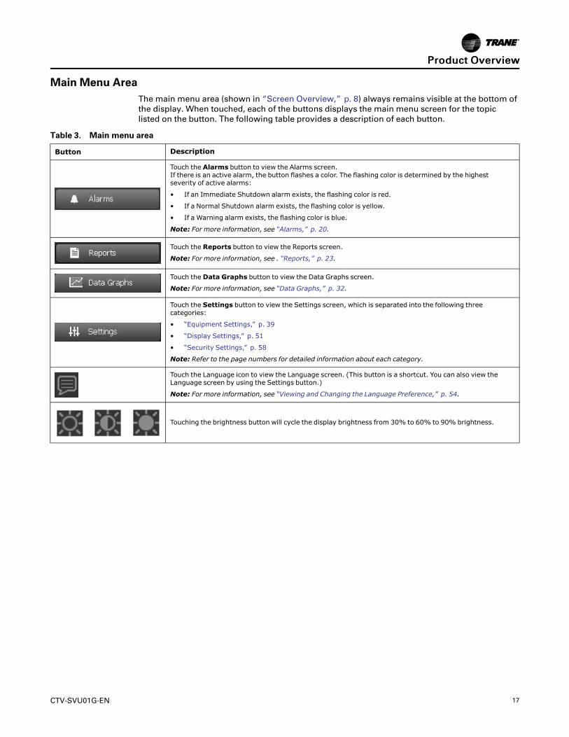
Main Menu AreaThe main menu area (shown in “Screen Overview,” p. 8) always remains visible at the bottom ofthe display. When touched, each of the buttons displays the main menu screen for the topiclisted on the button. The following table provides a description of each button.
Table 3. Main menu area
Button Description
Touch the Alarms button to view the Alarms screen.If there is an active alarm, the button flashes a color. The flashing color is determined by the highestseverity of active alarms:
• If an Immediate Shutdown alarm exists, the flashing color is red.
• If a Normal Shutdown alarm exists, the flashing color is yellow.
• If a Warning alarm exists, the flashing color is blue.
Note: For more information, see “Alarms,” p. 20.
Touch the Reports button to view the Reports screen.
Note: For more information, see . “Reports,” p. 23.
Touch the Data Graphs button to view the Data Graphs screen.
Note: For more information, see “Data Graphs,” p. 32.
Touch the Settings button to view the Settings screen, which is separated into the following threecategories:
• “Equipment Settings,” p. 39
• “Display Settings,” p. 51
• “Security Settings,” p. 58
Note: Refer to the page numbers for detailed information about each category.
Touch the Language icon to view the Language screen. (This button is a shortcut. You can also view theLanguage screen by using the Settings button.)
Note: For more information, see “Viewing and Changing the Language Preference,” p. 54.
Touching the brightness button will cycle the display brightness from 30% to 60% to 90% brightness.
PPrroodduucctt OOvveerrvviieeww

18 CTV-SVU01G-EN
Stopping/Restarting Chiller OperationYou can start or stop the chiller from the Tracer® AdaptiView™ display by using the Auto andStop buttons. The buttons are located in upper right.
Stopping the ChillerYou can stop the chiller in two ways:
• Normally, which involves stopping the various components sequentially in order to protectthem from damage
• Immediately, which shuts down all the components at once, and should be used only in anemergency
To stop the chiller in either of these ways:
1. Touch the Stop button to initiate the chiller shutdown process. A confirmation screen appearsas shown in the following figure.
Figure 6. Stop the Chiller confirmation screen
2. Touch the YYeess button. The Shutting Down Chiller screen appears as shown in the followingfigure.
• To stop the chiller normally, no further action is required. You can observe the submodeschange and the timers count down.
• To stop the chiller immediately, touch the IImmmmeeddiiaattee SShhuuttddoowwnn button.
• To cancel shutdown, touch the CCaanncceell SShhuuttddoowwnn button.

CTV-SVU01G-EN 19
Figure 7. Shutting Down Chiller screen
NNoottee:: If the chiller is a Duplex™, the screen shows top-level modes and submodes for boththe chiller and the two circuits.
Restarting the ChillerTouch the Auto button to initiate the chiller restart process. You can observe the mode change toAuto. The chiller will wait until cooling is needed before starting the compressor.
When the chiller is running normally, it automatically starts and stops as needed to reach itssetpoints.
SSttooppppiinngg//RReessttaarrttiinngg CChhiilllleerr OOppeerraattiioonn
20 CTV-SVU01G-EN
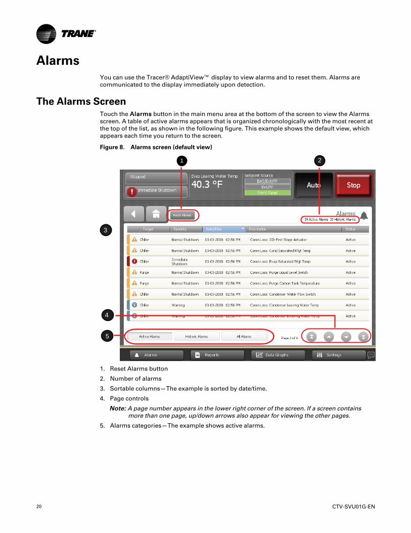
AlarmsYou can use the Tracer® AdaptiView™ display to view alarms and to reset them. Alarms arecommunicated to the display immediately upon detection.
The Alarms ScreenTouch the AAllaarrmmss button in the main menu area at the bottom of the screen to view the Alarmsscreen. A table of active alarms appears that is organized chronologically with the most recent atthe top of the list, as shown in the following figure. This example shows the default view, whichappears each time you return to the screen.
Figure 8. Alarms screen (default view)
1 2
3
4
5
1. Reset Alarms button
2. Number of alarms
3. Sortable columns—The example is sorted by date/time.
4. Page controls
NNoottee:: A page number appears in the lower right corner of the screen. If a screen containsmore than one page, up/down arrows also appear for viewing the other pages.
5. Alarms categories—The example shows active alarms.

CTV-SVU01G-EN 21
Alarm IconsAlarm icons, which appear in the left-most column of the alarms screen and on the alarmsindicator button if there is an existing alarm, are distinguished by their shape and color. Theirmeaning is explained in the following table.
Table 4. Alarm icons
Active alarm icons Historic alarm icons Level of severity
Red octagon Gray octagon
Immediate shutdown
Yellow triangle Gray triangle
Normal shutdown
Blue circle Gray circle
Warning
Active and Historic Alarm CategoriesYou can view alarms by three different categories:
• AAccttiivvee aallaarrmmss:: These are alarms that require attention. All alarms that are currently activeappear when you view this category.
• HHiissttoorriicc aallaarrmmss:: After an alarm condition has been resolved, the alarm is reclassified ashistoric. The 20 most recent historic alarms appear when you view this category.
• AAllll aallaarrmmss:: All active alarms and the 20 most recent historic alarms appear when you viewthis category. The alarms are listed in chronological order.
The Alarms screen defaults to active alarms, as in “The Alarms Screen,” p. 20. Note that theAAccttiivvee AAllaarrmmss button in Location 5 appears shaded in the figure, which indicates that you areviewing active alarms. To view a different category, touch HHiissttoorriicc AAllaarrmmss or AAllll AAllaarrmmss. Thebutton you select becomes shaded and the list appears.
Sorting AlarmsTo sort alarms by a category other than date and time, touch one of the other column headings inthe table. The column heading responds by changing to blue, and the alarms table re-sortsaccording to the blue column heading. If you touch the blue column heading again, the columnchanges the order from ascending to descending.
You can sort the alarms table by:
• Date/Time (the default sort): Most recent alarms are at the top.
• Severity: Active alarms are at the top (if you are viewing both active and historic alarms),followed by the most severe, followed by the most recent.
• Description: Alarms are sorted alphanumerically by name, followed by the most recent.
• Status: Alarms are sorted according to active/historic status (if you are viewing both activeand historic alarms), followed by the most recent.
AAllaarrmmss
22 CTV-SVU01G-EN
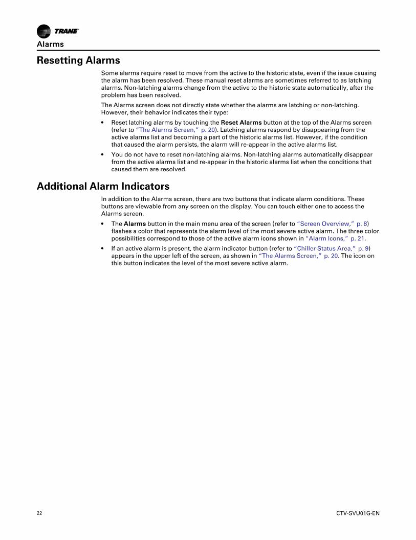
Resetting AlarmsSome alarms require reset to move from the active to the historic state, even if the issue causingthe alarm has been resolved. These manual reset alarms are sometimes referred to as latchingalarms. Non-latching alarms change from the active to the historic state automatically, after theproblem has been resolved.
The Alarms screen does not directly state whether the alarms are latching or non-latching.However, their behavior indicates their type:
• Reset latching alarms by touching the RReesseett AAllaarrmmss button at the top of the Alarms screen(refer to “The Alarms Screen,” p. 20). Latching alarms respond by disappearing from theactive alarms list and becoming a part of the historic alarms list. However, if the conditionthat caused the alarm persists, the alarm will re-appear in the active alarms list.
• You do not have to reset non-latching alarms. Non-latching alarms automatically disappearfrom the active alarms list and re-appear in the historic alarms list when the conditions thatcaused them are resolved.
Additional Alarm IndicatorsIn addition to the Alarms screen, there are two buttons that indicate alarm conditions. Thesebuttons are viewable from any screen on the display. You can touch either one to access theAlarms screen.
• The AAllaarrmmss button in the main menu area of the screen (refer to “Screen Overview,” p. 8)flashes a color that represents the alarm level of the most severe active alarm. The three colorpossibilities correspond to those of the active alarm icons shown in “Alarm Icons,” p. 21.
• If an active alarm is present, the alarm indicator button (refer to “Chiller Status Area,” p. 9)appears in the upper left of the screen, as shown in “The Alarms Screen,” p. 20. The icon onthis button indicates the level of the most severe active alarm.
AAllaarrmmss
CTV-SVU01G-EN 23
ReportsYou can use the Tracer® AdaptiView™ display to view a variety of reports and to create and edita custom report. All reports contain live data that refreshes every 2–5 seconds.
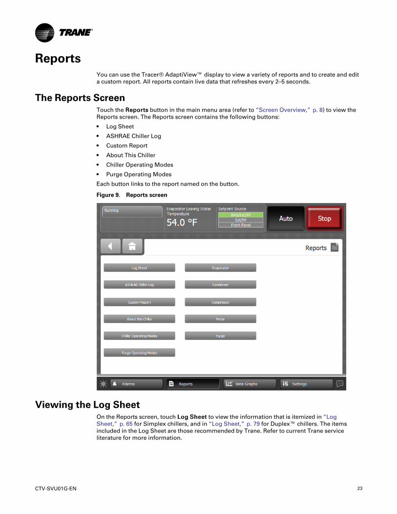
The Reports ScreenTouch the RReeppoorrttss button in the main menu area (refer to “Screen Overview,” p. 8) to view theReports screen. The Reports screen contains the following buttons:
• Log Sheet
• ASHRAE Chiller Log
• Custom Report
• About This Chiller
• Chiller Operating Modes
• Purge Operating Modes
Each button links to the report named on the button.
Figure 9. Reports screen
Viewing the Log SheetOn the Reports screen, touch LLoogg SShheeeett to view the information that is itemized in “LogSheet,” p. 65 for Simplex chillers, and in “Log Sheet,” p. 79 for Duplex™ chillers. The itemsincluded in the Log Sheet are those recommended by Trane. Refer to current Trane serviceliterature for more information.

24 CTV-SVU01G-EN
Viewing the ASHRAE Chiller LogOn the Reports screen, touch AASSHHRRAAEE CChhiilllleerr LLoogg to view the information that is itemized in“ASHRAE Chiller Log,” p. 67 for Simplex chillers, and in “ASHRAE Chiller Log,” p. 80 forDuplex™ chillers.
Creating and Viewing a Custom ReportYou can create a custom report in which you specify the type and order of data that it contains.Items available to select for a custom report are grouped according to subsystem. (For Simplexchillers, see “Items Available to Include in Custom Reports,” p. 69; for Duplex™ chillers, see“Items Available to Include in Custom Reports,” p. 82.)
To create and view a custom report:
1. On the Reports screen, touch CCuussttoomm RReeppoorrtt. The Custom Report screen appears.
2. On the Custom Report screen, touch EEddiitt. The Edit Custom Report screen appears in thefollowing figure.
Figure 10. Edit Custom Report screen
3. Touch the up/down arrows at the top of the left box on this screen to scroll through the itemsthat are available to add to a custom report.
4. To set up a custom report by adding:
• One item at a time, touch the item. It responds by changing to blue. Touch AAdddd to movethe selected item to the right box on the screen.
• All of the items at once to the right box on the screen, touch AAdddd AAllll.
NNoottee:: You can organize your selections in any order by using the down arrows that appearsin the right box, and by adding them one at a time in the order in which you want themto appear in your report.
5. To save and view your custom report, touch SSaavvee. The Custom Reports screen appears,containing the custom report you have just created as shown in the next figure.
RReeppoorrttss
CTV-SVU01G-EN 25
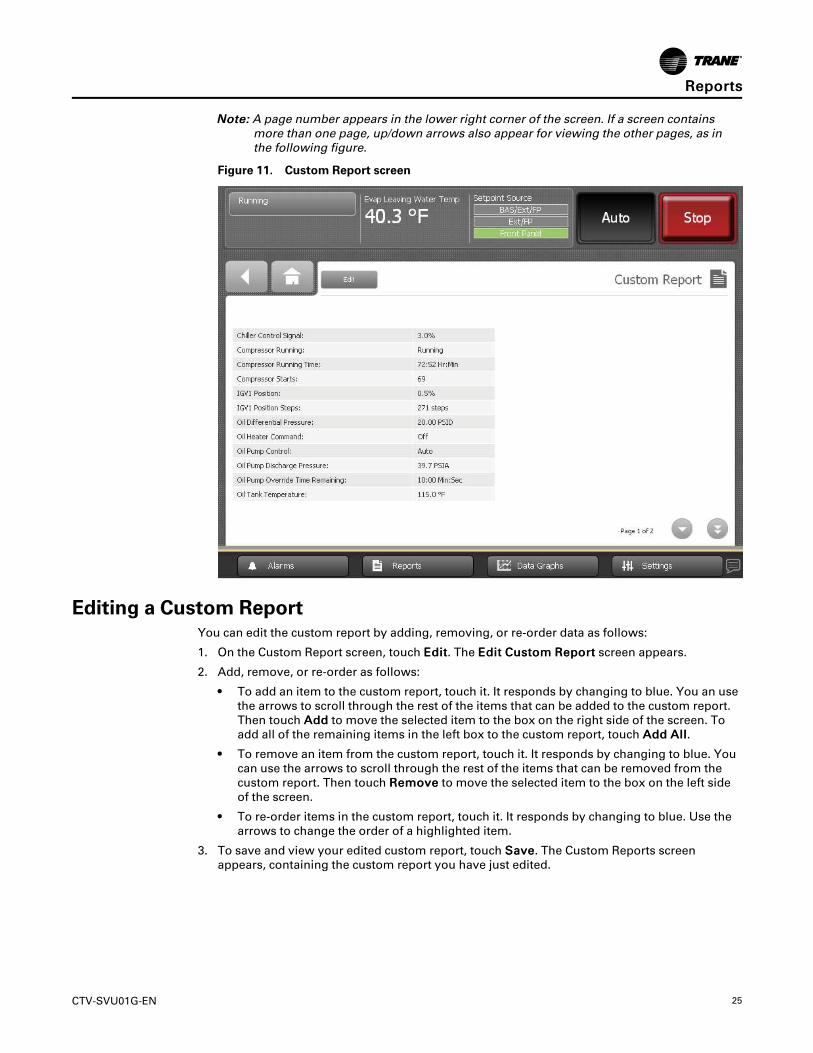
NNoottee:: A page number appears in the lower right corner of the screen. If a screen containsmore than one page, up/down arrows also appear for viewing the other pages, as inthe following figure.
Figure 11. Custom Report screen
Editing a Custom ReportYou can edit the custom report by adding, removing, or re-order data as follows:
1. On the Custom Report screen, touch EEddiitt. The EEddiitt CCuussttoomm RReeppoorrtt screen appears.
2. Add, remove, or re-order as follows:
• To add an item to the custom report, touch it. It responds by changing to blue. You an usethe arrows to scroll through the rest of the items that can be added to the custom report.Then touch AAdddd to move the selected item to the box on the right side of the screen. Toadd all of the remaining items in the left box to the custom report, touch AAdddd AAllll.
• To remove an item from the custom report, touch it. It responds by changing to blue. Youcan use the arrows to scroll through the rest of the items that can be removed from thecustom report. Then touch RReemmoovvee to move the selected item to the box on the left sideof the screen.
• To re-order items in the custom report, touch it. It responds by changing to blue. Use thearrows to change the order of a highlighted item.
3. To save and view your edited custom report, touch SSaavvee. The Custom Reports screenappears, containing the custom report you have just edited.
RReeppoorrttss
26 CTV-SVU01G-EN
About this ChillerOn the Reports screen, touch AAbboouutt TThhiiss CChhiilllleerr to view the following unit information:
• Chiller Name
• Chiller Model Number
• Chiller Sales Order Number
• Product Name
• Controller Build Part Number
• Chiller Serial Number
• Display Firmware Build
• Controller Hardware Serial Number
• Controller Boot Part Number
• Display Boot Code
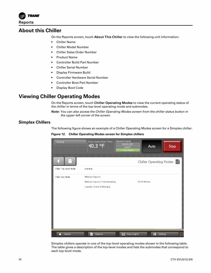
Viewing Chiller Operating ModesOn the Reports screen, touch CChhiilllleerr OOppeerraattiinngg MMooddeess to view the current operating status ofthe chiller in terms of the top-level operating mode and submodes.
NNoottee:: You can also access the Chiller Operating Modes screen from the chiller status button inthe upper left corner of the screen.
Simplex ChillersThe following figure shows an example of a Chiller Operating Modes screen for a Simplex chiller.
Figure 12. Chiller Operating Modes screen for Simplex chillers
Simplex chillers operate in one of the top-level operating modes shown in the following table.The table gives a description of the top-level modes and lists the submodes that correspond toeach top-level mode.
RReeppoorrttss

CTV-SVU01G-EN 27
Submodes are dependent on the top-level mode. Their appearance on the Chiller OperatingModes screen has the following characteristics:
• The newest submode appears at the top of the submode list.
• Submodes disappear when they no longer apply.
• The screen displays up to six submodes.
• If less than six submodes are active, the submode rows that do not apply are blank.
Table 5. Chiller top-level operating modes and corresponding submodes for Simplex chillers
Top-level mode Description Corresponding submodes
Stopped Chiller is inhibited from running and requires user action to goto Auto.
Local Stop
Immediate Stop
Diagnostic Shutdown—Manual Reset
Run InhibitUnit is inhibited from running by building automation system(BAS), external control source (Ext), or Auto Reset diagnostic
Ice Building Is Complete
Tracer Inhibit
External Source Inhibit
Diagnostic Shutdown—Auto Reset
Auto Unit is determining if there is a need to run.
Waiting for Evaporator Water Flow
Waiting for a Need to Cool
Waiting for a Need to Heat
Power Up Delay Inhibit (MIN:SEC)(a)
Waiting to Start Unit is waiting for tasks required prior to compressor start to becompleted.
Waiting For Condenser Water Flow
Establishing Oil Pressure
Pre-Lubrication Time (MIN:SEC)(a)
Motor Temperature Inhibit: Motor Temperature/Inhibit Temperature
Restart Time Inhibit (MIN:SEC)(a)
AFD Restart Inhibit
High Vacuum Inhibit: Oil Sump Press/InhibitPress
Low Oil Temperature Inhibit: Oil Temperature/Inhibit Temperature
Waiting for Starter To Start (MIN:SEC)(a)
Starting Compressor Unit is starting compressor. No submode is shown
Running Compressor is running with no limits in effect.
No submode is shown
Hot Water Control
Surge
Base Loaded
Hot Gas Bypass
Ice Building
Ice To Normal Transition
Current Control Soft Loading
RReeppoorrttss
28 CTV-SVU01G-EN
Table 5. Chiller top-level operating modes and corresponding submodes for Simplex chillers (continued)
Top-level mode Description Corresponding submodes
Running—Limit Compressor is running with limits in effect.
Current Limit
Phase Unbalance Limit
Condenser Pressure Limit
Evaporator Temperature Limit
Evaporator Rfgt Temperature Higher ThanSelection
Minimum Capacity Limit
Maximum Capacity Limit
Free Cooling Unit is in Free Cooling mode and will not run the compressor.Opening Free Cooling Valves
Closing Free Cooling Limit
Preparing to Shutdown Unit is closing inlet guide vanes prior to compressor shutdown. Closing IGV (IGV Position %)(b)
Shutting Down Compressor has been stopped and unit is performing shutdowntasks.
Post-Lubrication Time (MIN:SEC)(a)
Evaporator Pump Off Delay (MIN:SEC(a)
Condenser Pump Off Delay (MIN:SEC)(a)
Satisfied Need to Minimum Capacity Timer (willappear for only 10 seconds)
(a) “MIN:SEC” refers to a count-down timer that appears on the screen to indicate how long the submode will remain active.(b) “IGV Position %” refers to a value that indicates the position of the inlet guide vane (IGV).
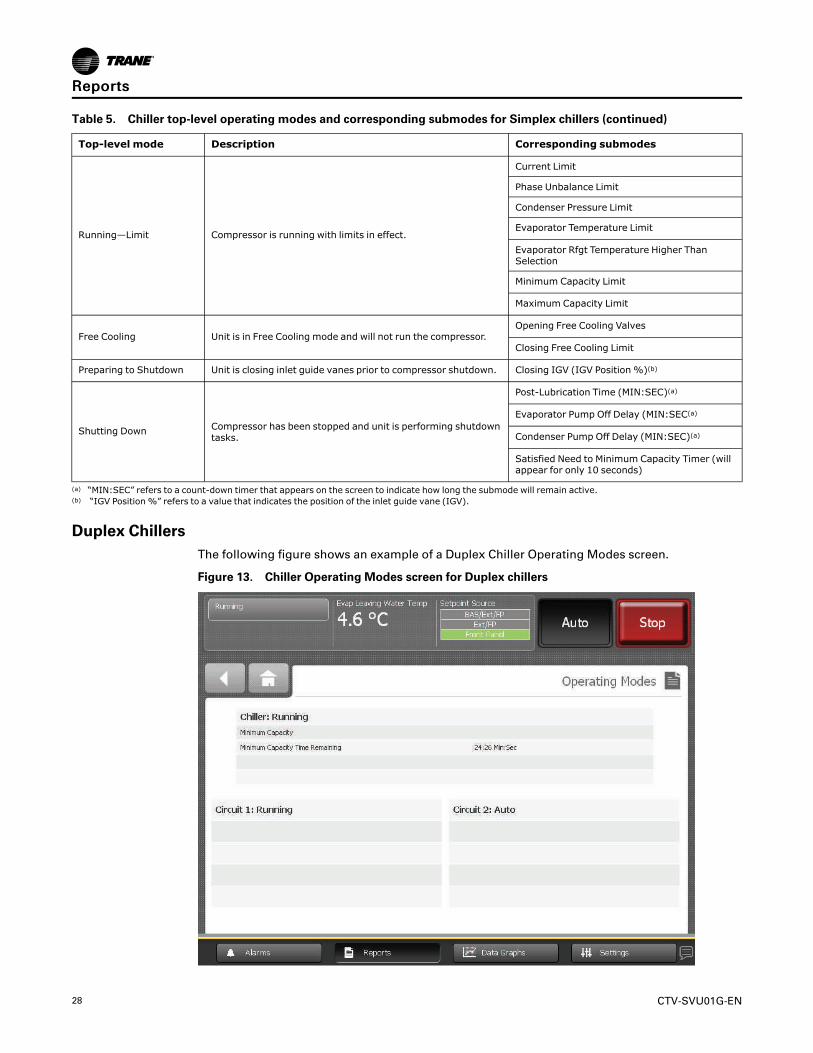
Duplex ChillersThe following figure shows an example of a Duplex Chiller Operating Modes screen.
Figure 13. Chiller Operating Modes screen for Duplex chillers
RReeppoorrttss

CTV-SVU01G-EN 29
For Duplex™ chillers, the Chiller Operating Modes screen shows top-level modes and submodesfor the chiller (Table 6, p. 29) and for the circuits (Table 7, p. 30). Each table shows top-levelmodes in the left column, a description in the middle column, and the corresponding submodesin the right column.
Submodes are dependent on the top-level mode. They appear on the Chiller Operating Modesscreen with the following characteristics:
• The newest submode appears at the top of the submode list.
• Submodes disappear when they no longer apply.
• The screen displays up to four submodes.
• If less than four submodes are active, the submode rows that do not apply are blank.
Table 6. Chiller top-level operating modes and corresponding submodes for Duplex chillers
Top-level mode Description Corresponding submodes
Stopped The chiller is not running either circuit and cannot run withoutintervention.
Local Stop
Immediate Stop
Diagnostic Shutdown—Manual Reset
Run InhibitThe chiller is currently being inhibited from starting (andrunning), but may be allowed to start if the inhibiting ordiagnostic condition is cleared.
Ice Building Is Complete
Start Inhibited By BAS
Waiting for BAS Communication
External Source Inhibit
Diagnostic Shutdown—Auto Reset
No Circuits Available
AutoThe chiller is not currently running but can be expected to startat any moment given that the proper conditions and interlocksare satisfied.
Waiting for Evaporator Water Flow
Waiting for a Need to Cool
Waiting for a Need to Heat
Power Up Display Inhibit (MIN:SEC)(a)
Waiting to Start The chiller is going through the necessary steps to allow thelead circuit to start.
The chiller will wait up to 4 minutes and 15seconds in this mode for condenser water flowto be established by means of the flow switchhardwired input.
Running At least one circuit on the chiller is currently running.
Hot Water Control
Base Loaded
Ice Building
Ice To Normal Transition (MIN:SEC)(a)
Current Control Softloading
Capacity Control Softloading
Minimum Capacity Limit
Running—Limit
At least one circuit on the chiller is currently running, but theoperation of the chiller as a whole is being actively limited bythe controls. The submodes that apply the Running top modesmay be displayed along with the following limit-specific modes.
All of the chiller-level Running submodes apply.There are no specific submodes associated withRunning—Limit.
RReeppoorrttss

30 CTV-SVU01G-EN
Table 6. Chiller top-level operating modes and corresponding submodes for Duplex chillers (continued)
Top-level mode Description Corresponding submodes
Shutting Down The chiller is still running, but shutdown is imminent. Thechiller is going through a compressor run-unload.
Evaporator Pump Off Delay (MIN:SEC)(a)
Condenser Pump Off Delay (MIN:SEC)(a)
Satisfied Need to Cool
Satisfied Need to Heat
Satisfied Need to Minimum Capacity Timer (willdisplay for only 10 seconds)
Miscellaneous These submodes may appear with most of the top-level chillermodes.
Evaporator Pump Off Override
Condenser Pump Override
Manual Capacity Override
IGV Manual Override(b)
Software Service Lock
(a) “MIN:SEC” refers to a count-down timer that appears on the screen to indicate how long the submode will remain active.(b) “IGV Position %” refers to a value that indicates the position of the inlet guide vane (IGV).
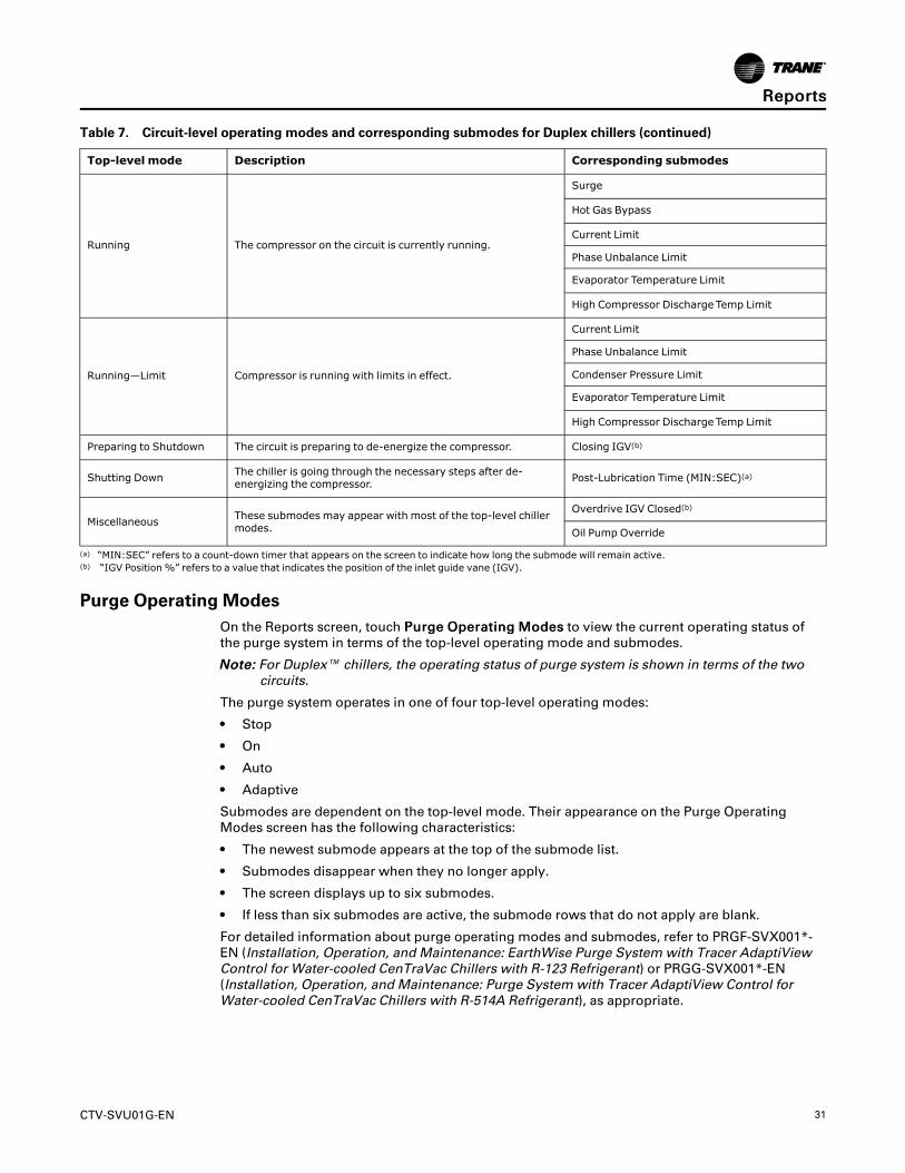
Table 7. Circuit-level operating modes and corresponding submodes for Duplex chillers
Top-level mode Description Corresponding submodes
Stopped The circuit is not running, and cannot run without intervention.Diagnostic Shutdown—Manual Reset
Front Panel Circuit Lockout
Run InhibitThe circuit is currently being inhibited from starting (andrunning), but may be allowed to start if the inhibiting ordiagnostic condition is cleared.
Diagnostic Shutdown—Auto Reset
External Circuit Lockout
AutoThe circuit is currently not running but is expected to start atany moment if the proper conditions are satisfied. No Circuit Submodes
Waiting To Start The chiller is going through the necessary steps to allow thelead circuit to start.
Waiting for Low Oil Differential Pressure
Establishing Oil Pressure
Pre-Lubrication Time (MIN:SEC)(a)
Motor Temperature Inhibit: Motor Temperature/Inhibit Temperature
Restart Time Inhibit (MIN:SEC)(a)
High Vacuum Inhibit: Oil Sump Press/InhibitPress
Low Oil Temperature Inhibit: Oil Temperature/Inhibit Temperature
Waiting for Starter To Start (MIN:SEC)(a)
Waiting for IGV Positioning to Complete(b)
Waiting for Starter Interlock
Starting Compressor The circuit is going through the necessary steps to allow thecompressor on that circuit to start. No submodes
RReeppoorrttss
CTV-SVU01G-EN 31
Table 7. Circuit-level operating modes and corresponding submodes for Duplex chillers (continued)
Top-level mode Description Corresponding submodes
Running The compressor on the circuit is currently running.
Surge
Hot Gas Bypass
Current Limit
Phase Unbalance Limit
Evaporator Temperature Limit
High Compressor Discharge Temp Limit
Running—Limit Compressor is running with limits in effect.
Current Limit
Phase Unbalance Limit
Condenser Pressure Limit
Evaporator Temperature Limit
High Compressor Discharge Temp Limit
Preparing to Shutdown The circuit is preparing to de-energize the compressor. Closing IGV(b)
Shutting Down The chiller is going through the necessary steps after de-energizing the compressor. Post-Lubrication Time (MIN:SEC)(a)
Miscellaneous These submodes may appear with most of the top-level chillermodes.
Overdrive IGV Closed(b)
Oil Pump Override
(a) “MIN:SEC” refers to a count-down timer that appears on the screen to indicate how long the submode will remain active.(b) “IGV Position %” refers to a value that indicates the position of the inlet guide vane (IGV).
Purge Operating ModesOn the Reports screen, touch PPuurrggee OOppeerraattiinngg MMooddeess to view the current operating status ofthe purge system in terms of the top-level operating mode and submodes.
NNoottee:: For Duplex™ chillers, the operating status of purge system is shown in terms of the twocircuits.
The purge system operates in one of four top-level operating modes:
• Stop
• On
• Auto
• Adaptive
Submodes are dependent on the top-level mode. Their appearance on the Purge OperatingModes screen has the following characteristics:
• The newest submode appears at the top of the submode list.
• Submodes disappear when they no longer apply.
• The screen displays up to six submodes.
• If less than six submodes are active, the submode rows that do not apply are blank.
For detailed information about purge operating modes and submodes, refer to PRGF-SVX001*-EN (Installation, Operation, and Maintenance: EarthWise Purge System with Tracer AdaptiViewControl for Water-cooled CenTraVac Chillers with R-123 Refrigerant) or PRGG-SVX001*-EN(Installation, Operation, and Maintenance: Purge System with Tracer AdaptiView Control forWater-cooled CenTraVac Chillers with R-514A Refrigerant), as appropriate.
RReeppoorrttss

32 CTV-SVU01G-EN
Data GraphsYou can use the Tracer® AdaptiView™ display to view a variety of default data graphs and tocreate up to six custom data graphs with up to eight data points per graph. The data sample rateis 30 seconds, and the data storage duration is 48 hours. These rates cannot be adjusted.
The Data Graphs ScreenTouch the DDaattaa GGrraapphhss button in the main menu area to view the Data Graphs screen shown inthe following figure. Each button on the screen links to a data graph.
The buttons under the Default Graphs heading for Simplex chillers are:
• Chiller Overview 1• Chiller Overview 2• Approach Temperature• Evaporator• Motor• Condenser• Motor Temperature• Compressor• Purge• Oil System or Lube System
When you create custom graphs, they appear under the Custom Graphs heading with namessuch as “Custom 1” and “Custom 2,” as shown in the following figure.
Figure 14. Data Graphs screen
The buttons under the Default Graphs heading for Duplex™ chillers are:
CChhiilllleerr
• Chiller Overview 1
CTV-SVU01G-EN 33
• Chiller Overview 2• Evaporator• Condenser
CCiirrccuuiitt 11
• Oil System• Approach Temperature• Compressor• Motor• Motor Temperature• Purge
CCiirrccuuiitt 22
• Oil System• Approach Temperature• Compressor• Motor• Motor Temperature• Purge
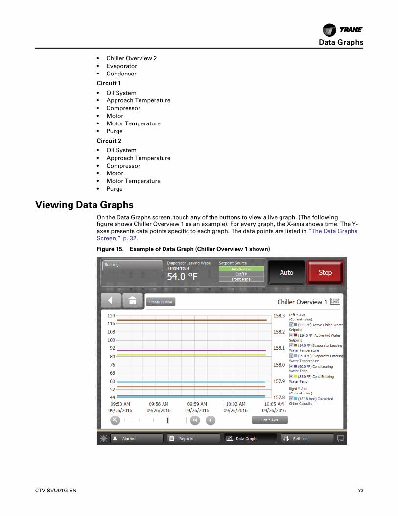
Viewing Data GraphsOn the Data Graphs screen, touch any of the buttons to view a live graph. (The followingfigure shows Chiller Overview 1 as an example). For every graph, the X-axis shows time. The Y-axes presents data points specific to each graph. The data points are listed in “The Data GraphsScreen,” p. 32.
Figure 15. Example of Data Graph (Chiller Overview 1 shown)
DDaattaa GGrraapphhss
34 CTV-SVU01G-EN
Changing the Scales on Data GraphsCChhaannggiinngg tthhee SSccaallee ooff tthhee XX--aaxxiissThe X-axis scale defaults to the most recent 60 minutes with 15 minutes in between the timelabels that appear across the bottom of the graph. You can change the scale from the last 12minutes to the last 2 days and increments in between, as follows:
• 12-minute graph with 3 minutes between time labels• 40-minute graph with 10 minutes between time labels• 60-minute graph with 15 minutes between time labels• 4-hour graph with 1 hour between time labels• 8-hour graph with 2 hours between time labels• 1-day graph with 6 hours between time labels• 2-day graph with 12 hours between time labels
To change the scale, touch the plus or minus button in the magnifying glass in the lower leftcorner of a data graph that you want to edit (for an example, refer to the figure in “Viewing DataGraphs,” p. 33). The slider scale moves to the right or left as you touch either the plus or minusbutton. The time scale for the X-axis changes in response.
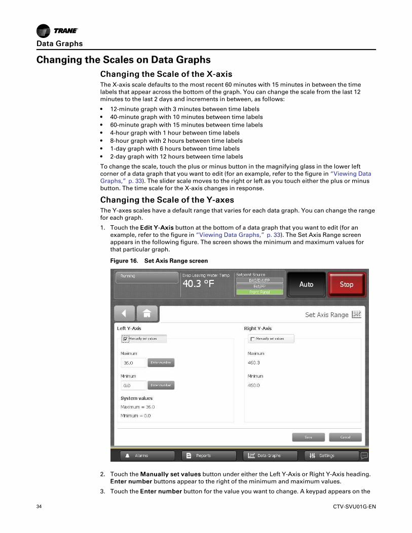
CChhaannggiinngg tthhee SSccaallee ooff tthhee YY--aaxxeessThe Y-axes scales have a default range that varies for each data graph. You can change the rangefor each graph.
1. Touch the EEddiitt YY--AAxxiiss button at the bottom of a data graph that you want to edit (for anexample, refer to the figure in “Viewing Data Graphs,” p. 33). The Set Axis Range screenappears in the following figure. The screen shows the minimum and maximum values forthat particular graph.
Figure 16. Set Axis Range screen
2. Touch the MMaannuuaallllyy sseett vvaalluueess button under either the Left Y-Axis or Right Y-Axis heading.EEnntteerr nnuummbbeerr buttons appear to the right of the minimum and maximum values.
3. Touch the EEnntteerr nnuummbbeerr button for the value you want to change. A keypad appears on the
DDaattaa GGrraapphhss
CTV-SVU01G-EN 35
screen.
4. Touch the appropriate numbers to change the current value. The new value appears abovethe keypad.
5. Touch the EEnntteerr button. The graph you were previously viewing appears with changedmaximum and/or minimum values.
6. Touch SSaavvee. The data graph appears with changed Y-axes scales.
Creating Custom Data GraphsYou can create a custom data graph in two ways:
• By starting with a default data graph
• By starting from a blank screen, with no previously defined data graph points
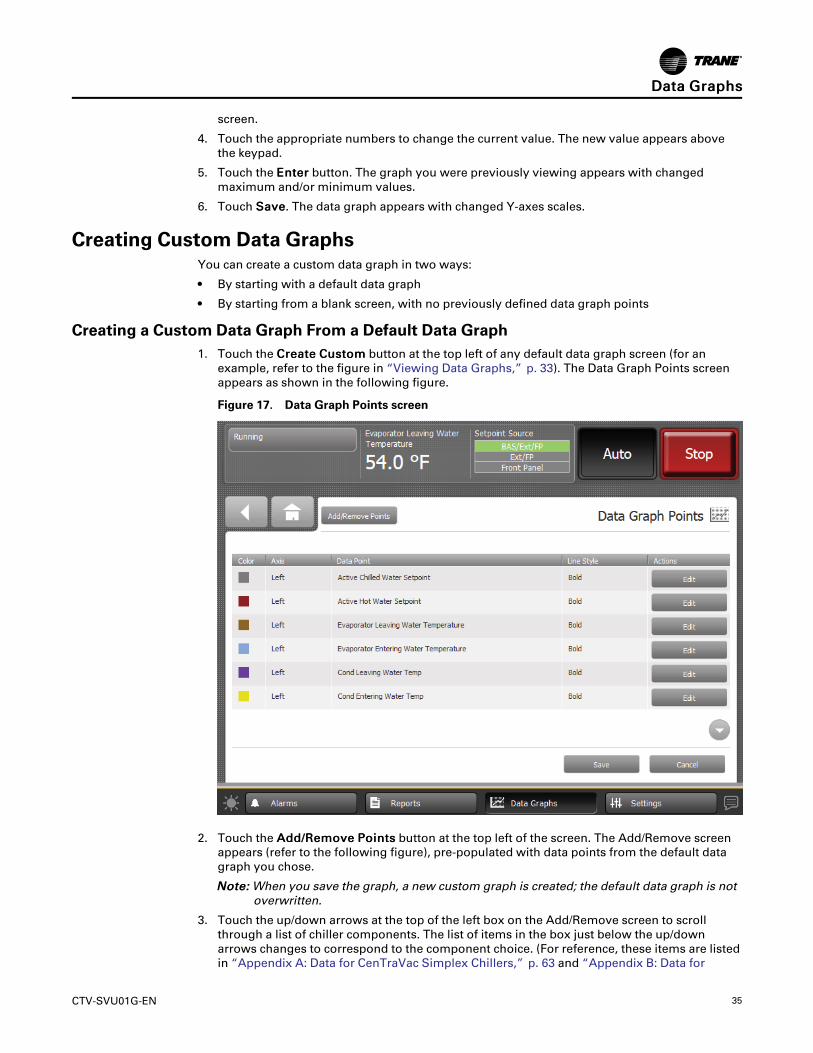
Creating a Custom Data Graph From a Default Data Graph1. Touch the CCrreeaattee CCuussttoomm button at the top left of any default data graph screen (for an
example, refer to the figure in “Viewing Data Graphs,” p. 33). The Data Graph Points screenappears as shown in the following figure.
Figure 17. Data Graph Points screen
2. Touch the AAdddd//RReemmoovvee PPooiinnttss button at the top left of the screen. The Add/Remove screenappears (refer to the following figure), pre-populated with data points from the default datagraph you chose.
NNoottee:: When you save the graph, a new custom graph is created; the default data graph is notoverwritten.
3. Touch the up/down arrows at the top of the left box on the Add/Remove screen to scrollthrough a list of chiller components. The list of items in the box just below the up/downarrows changes to correspond to the component choice. (For reference, these items are listedin “Appendix A: Data for CenTraVac Simplex Chillers,” p. 63 and “Appendix B: Data for
DDaattaa GGrraapphhss
36 CTV-SVU01G-EN
CenTraVac Duplex Chillers ,” p. 77).
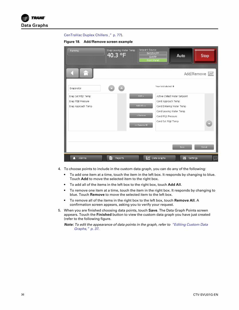
Figure 18. Add/Remove screen example
4. To choose points to include in the custom data graph, you can do any of the following:
• To add one item at a time, touch the item in the left box. It responds by changing to blue.Touch AAdddd to move the selected item to the right box.
• To add all of the items in the left box to the right box, touch AAdddd AAllll.
• To remove one item at a time, touch the item in the right box. It responds by changing toblue. Touch RReemmoovvee to move the selected item to the left box.
• To remove all of the items in the right box to the left box, touch RReemmoovvee AAllll. Aconfirmation screen appears, asking you to verify your request.
5. When you are finished choosing data points, touch SSaavvee. The Data Graph Points screenappears. Touch the FFiinniisshheedd button to view the custom data graph you have just created(refer to the following figure.
NNoottee:: To edit the appearance of data points in the graph, refer to “Editing Custom DataGraphs,” p. 37.
DDaattaa GGrraapphhss
CTV-SVU01G-EN 37
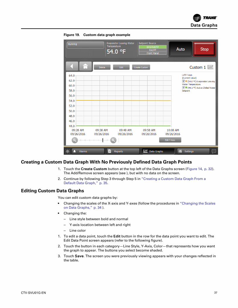
Figure 19. Custom data graph example
Creating a Custom Data Graph With No Previously Defined Data Graph Points1. Touch the CCrreeaattee CCuussttoomm button at the top left of the Data Graphs screen (Figure 14, p. 32).
The Add/Remove screen appears (see ), but with no data on the screen.
2. Continue by following Step 3 through Step 5 in “Creating a Custom Data Graph From aDefault Data Graph,” p. 35.
Editing Custom Data GraphsYou can edit custom data graphs by:
• Changing the scales of the X-axis and Y-axes (follow the procedures in “Changing the Scaleson Data Graphs,” p. 34 ).
• Changing the:
– Line style between bold and normal
– Y-axis location between left and right
– Line color
1. To edit a data point, touch the EEddiitt button in the row for the data point you want to edit. TheEdit Data Point screen appears (refer to the following figure).
2. Touch the button in each category—Line Style, Y-Axis, Color—that represents how you wantthe graph to appear. The buttons you select become shaded.
3. Touch SSaavvee. The screen you were previously viewing appears with your changes reflected inthe table.
DDaattaa GGrraapphhss

38 CTV-SVU01G-EN
Figure 20. Edit Data Point screen
Deleting a Custom Data GraphTouch the DDeelleettee button at the top of a custom graph screen to delete the custom graph.
DDaattaa GGrraapphhss
CTV-SVU01G-EN 39
Equipment SettingsYou can use the Tracer® AdaptiView™ display to monitor and change a variety of equipmentsettings.
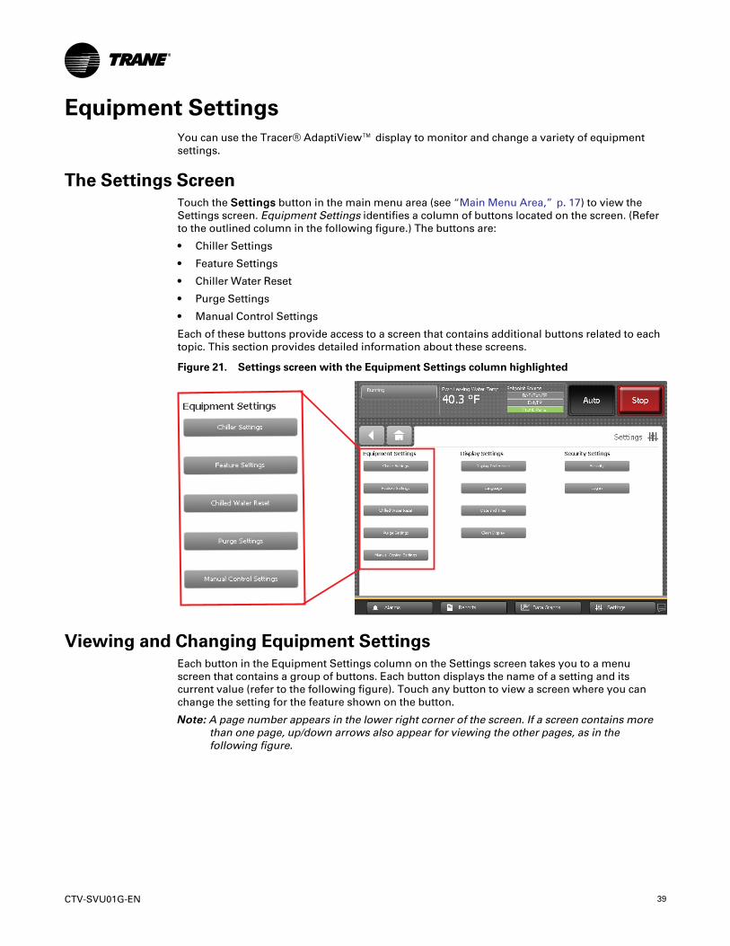
The Settings ScreenTouch the SSeettttiinnggss button in the main menu area (see “Main Menu Area,” p. 17) to view theSettings screen. Equipment Settings identifies a column of buttons located on the screen. (Referto the outlined column in the following figure.) The buttons are:
• Chiller Settings
• Feature Settings
• Chiller Water Reset
• Purge Settings
• Manual Control Settings
Each of these buttons provide access to a screen that contains additional buttons related to eachtopic. This section provides detailed information about these screens.
Figure 21. Settings screen with the Equipment Settings column highlighted
Viewing and Changing Equipment SettingsEach button in the Equipment Settings column on the Settings screen takes you to a menuscreen that contains a group of buttons. Each button displays the name of a setting and itscurrent value (refer to the following figure). Touch any button to view a screen where you canchange the setting for the feature shown on the button.
NNoottee:: A page number appears in the lower right corner of the screen. If a screen contains morethan one page, up/down arrows also appear for viewing the other pages, as in thefollowing figure.

40 CTV-SVU01G-EN
Figure 22. Example equipment settings screen (Chiller Settings shown)
To change an equipment setting, follow this procedure:
1. Touch one of the buttons in the Equipment Settings column on the Settings screen, such asChiller Settings. The corresponding screen appears (in this case, the Chiller Settings screen).
2. Touch the button that shows the equipment setting you want to change. A screen that allowsyou to change the equipment setting appears. There are two types of these screens:
• For screens with button selections, touch the button that represents the setting you want.The button becomes shaded, and a SSaavvee button appears at the bottom of the screen asshown in the following figure.
EEqquuiippmmeenntt SSeettttiinnggss
CTV-SVU01G-EN 41
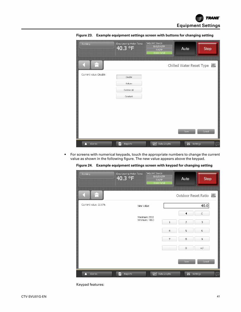
Figure 23. Example equipment settings screen with buttons for changing setting
• For screens with numerical keypads, touch the appropriate numbers to change the currentvalue as shown in the following figure. The new value appears above the keypad.
Figure 24. Example equipment settings screen with keypad for changing setting
Keypad features:
EEqquuiippmmeenntt SSeettttiinnggss

42 CTV-SVU01G-EN
– When you enter a new number, the value in the NNeeww vvaalluuee field is deleted andreplaced with the new entry.
– The backspace (arrow) key deletes the characters you previously entered.
– If the keypad is used to enter a setpoint that is out of range, an error dialog willappear when you touch the SSaavvee button.
– Keypads that allow negative numbers have positive and negative number (+/-)keys.
3. Touch SSaavvee to complete the change. The current value is updated in the upper left side of thescreen, demonstrating that the change has been communicated to the Tracer UC800controller. The screen you were previously viewing appears.
NNoottee:: Manual Control Settings screens have Apply buttons in addition to Save buttons. Foran example, refer to “Manual Control Settings,” p. 47. Touching Apply is the same astouching Save, except that you remain at the current screen after the change iscommunicated to the Tracer® UC800 controller.
Chiller SettingsThe following table lists the settings that are available as buttons on the Chiller Settings menuscreen, along with their corresponding setting options. The chiller configuration determineswhich of the settings appear.
Table 8. Chiller Settings menu screen: Buttons and available setting options
Page 1 of 2
Setpoint SourceBAS/Ext/FPExt/FPFront Panel
Front Panel Control TypeCooling/ Heating
Front Panel Chilled Water SetpointXX.X °F/C
Front Panel Hot Water SetpointXXX.X °F/C
Front Panel Ice Building CommandAuto/On
Front Panel Ice Termination SetpointXX.X °F/C
Ice to Normal Cooling Timer SetpointXX Min
Front Panel Current Limit SetpointXXX.X %
Front Panel Base Loading SetpointXXX.X %
Front Panel Base Loading CommandAuto/On
Page 2 of 2
Differential to StartXX.X °F/C
Differential to StopXX.X °F/C
Front Panel Free Cooling CommandAuto/On
Condenser Water Pump Off DelayXX Min
Evaporator Water Pump Off DelayXX Min
Evap LowWater Flow WarningSetpointXXXX.X gpm/lpm
Power-Up Start DelayXXX Sec
Starter Power Demand Time PeriodXXX Min
EEqquuiippmmeenntt SSeettttiinnggss

CTV-SVU01G-EN 43
Service SettingsThe following table lists the settings that are available as buttons on the Service Settings menuscreen, along with their corresponding setting options. The chiller configuration determineswhich of the settings appear.
Table 9. Service Settings menu screen: Buttons and available settings options
Page 1 of 2
Evaporator Leaving Water Temp CutoutXX.X °F/C
Low Refrigerant Temperature CutoutXX.X °F/C
Local Atmospheric PressureXX.X PSI/kPa
Maximum Capacity LimitXXX.X %
Minimum Capacity LimitXXX.X%(Formerly in Chiller Settings)
BAS Setpoint Power Loss Store EnableEnable/Disable
Check Oil Filter SetpointXX.XX PSID/kPaD-or-Check Lube Filter SetpointXX.XX PSID/kPaD(CVHS Only)
Startup Lube Diff Pressure ThresholdXX.XX PSID/kPaD(CVHS Only)
Capacity Control Softload TimeXXX Sec
Current Limit Control Softload TimeXXX Sec
Current Limit Softload Start PointXXX.X %
Page 2 of 2
Condenser Limit SetpointXXX.X %
Head Pressure Control Pre-Position SetpointXXX.X%
Head Pressure Control Pre-Position SetpointXXX.X %
Staging On BoundaryXXX.X %(Duplex Only)
Staging Off BoundaryXXX.X%(Duplex Only)
Setpoint SourcesSome setpoints can be controlled from more than one source; these are referred to as arbitratedsetpoints. Arbitrated setpoints can be:
• Communicated from a building automation system (BAS)—Refers to a Trane or other BASthat can communicate with chiller controls over a network.
• Set by an external control source (Ext)—Refers to inputs that are hard-wired directly to localchiller controls, carrying low-voltage binary (On/Off) or analog (0–10 Vdc, 4–20 mA) signals.
• Set at the front panel (FP)—Refers to inputs that are entered by an operator using the Tracer®AdaptiView™ display or by a technician using the Tracer® TU service tool.
Setpoint Source ArbitrationThe Tracer® UC800 uses a process referred to as setpoint source arbitration to prioritize theselection of the setpoint source. The following table provides an explanation of how this processworks.
Table 10. Setpoint source choices and corresponding arbitration
Priority BAS/Ext/FP Ext/FP Front Panel
First Setpoint from the BAS is used. Setpoint from a external control source isused.
Setpoint from the front panel is used.
Note: Any setpoint from a BAS or externalcontrol source is ignored.
Second
If no BAS setpoint is available (forexample, BAS communication hasnever been established), a setpointfrom an external control source isused.
If no externally controlled setpoint isavailable, a setpoint from the front panelis used.
Note: Any setpoint from a BAS is ignored.
None
EEqquuiippmmeenntt SSeettttiinnggss
44 CTV-SVU01G-EN
Table 10. Setpoint source choices and corresponding arbitration (continued)
Priority BAS/Ext/FP Ext/FP Front Panel
Third
If no BAS nor external setpoint isavailable (for example, BAScommunication has never beenestablished), a setpoint from the frontpanel is used.
None None
Notes:1. For service or troubleshooting, it may be helpful to set the setpoint source to front panel to isolate the chiller from other control sources.2. If BAS communication was established and then lost, in most instances the BAS values remain and can be used by the chiller controller.
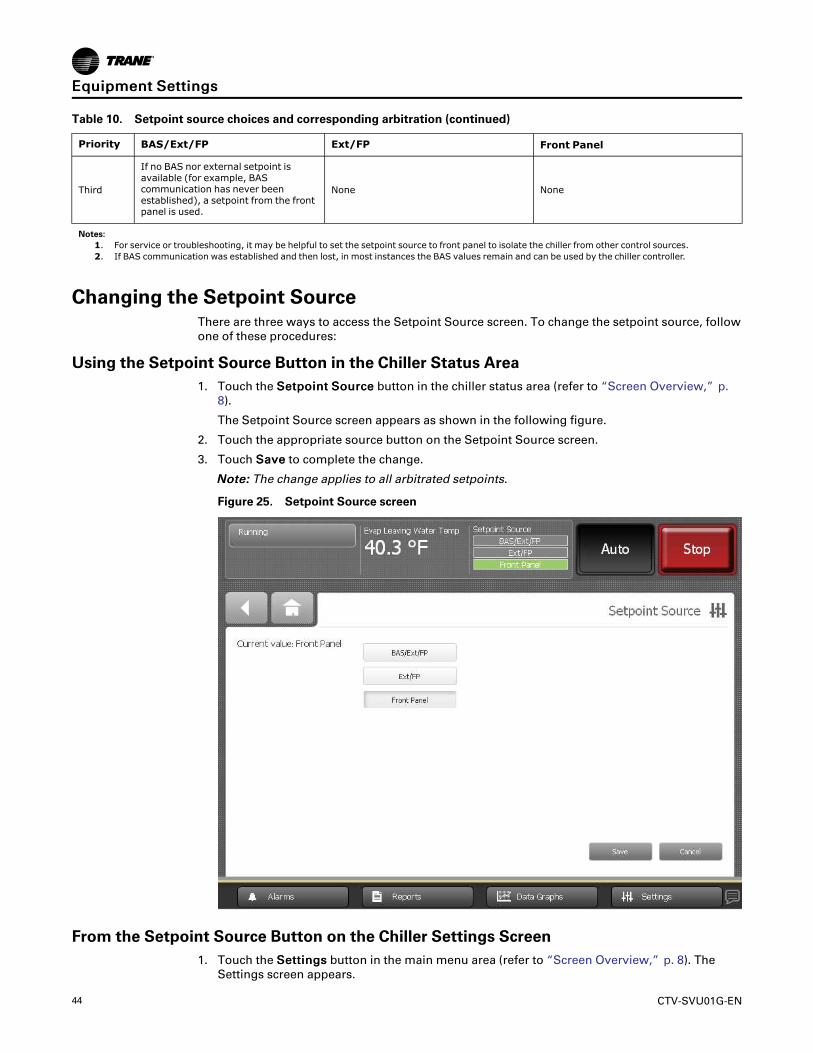
Changing the Setpoint SourceThere are three ways to access the Setpoint Source screen. To change the setpoint source, followone of these procedures:
Using the Setpoint Source Button in the Chiller Status Area1. Touch the SSeettppooiinntt SSoouurrccee button in the chiller status area (refer to “Screen Overview,” p.
8).
The Setpoint Source screen appears as shown in the following figure.
2. Touch the appropriate source button on the Setpoint Source screen.
3. Touch SSaavvee to complete the change.
NNoottee:: The change applies to all arbitrated setpoints.
Figure 25. Setpoint Source screen
From the Setpoint Source Button on the Chiller Settings Screen1. Touch the SSeettttiinnggss button in the main menu area (refer to “Screen Overview,” p. 8). The
Settings screen appears.
EEqquuiippmmeenntt SSeettttiinnggss

CTV-SVU01G-EN 45
2. From the Settings screen, touch the CChhiilllleerr SSeettttiinnggss button. The Chiller Settings screenappears.
3. From the Chiller Settings screen, touch the button that is labeled “Setpoint Source” anddisplays the current source. The Setpoint Source screen appears (refer to the precedingfigure).
4. Touch the button the appropriate source button on the Setpoint Source screen.
5. Touch SSaavvee to complete the change.
NNoottee:: The change applies to all arbitrated setpoints.
From an Arbitrated Setpoint Screen1. Touch the SSeettttiinnggss button in the main menu area (Figure 2, p. 9). The Settings screen
appears.
2. From the Settings screen, touch the CChhiilllleerr SSeettttiinnggss button. The Chiller Settings screenappears.
3. From the Chiller Settings screen, touch an arbitrated setpoint. The setpoint screen for thatspecific arbitrated setpoint appears (see the following figure for an example).
4. On the arbitrated setpoint screen, touch the Setpoint Source button. The Setpoint Sourcescreen appears (refer to the preceding figure).
5. Touch the button the appropriate source button on the Setpoint Source screen.
6. Touch SSaavvee to complete the change.
NNoottee:: The change applies to all arbitrated setpoints.
Figure 26. Changing the setpoint source from an arbitrated setpoint screen
EEqquuiippmmeenntt SSeettttiinnggss

46 CTV-SVU01G-EN
Feature SettingsThe following table lists the settings that are available as buttons on the Feature Settings menuscreen, along with their corresponding setting options. The chiller configuration determineswhich of the settings appear.
Table 11. Feature Settings menu screen: Buttons and available setting options
Ext Chilled Wtr SetptEnable/Disable
Ext Current Limit SetptEnable/Disable
Ice BuildingEnable/Disable
Ext Chilled Wtr SetptEnable/Disable
Ext Current Limit SetptEnable/Disable
Ice BuildingEnable/Disable
Hot Gas Bypass FeatureEnable/Disable
Hot Gas Bypass Maximum TimerEnableEnable/Disable
SecurityEnable/Disable
LCI-C Diagnostic EncodingText/Code
External Base Loading SetpointEnable/Disable
Check Oil Filter Diagnostic Ckt1Enable/Disable-or-Check Lube Filter DiagnosticEnable/Disable(CVHS Only)
Check Oil Filter Diagnostic Ckt2Enable/Disable
Chilled Water ResetThe following table lists the settings that are available as buttons on the Chilled Water Resetmenu screen, along with their corresponding setting options. The chiller configurationdetermines which of the settings appear.
Table 12. Chilled Water Reset menu screen: Buttons and available setting options
Buttons Available setting options
Chilled Water Reset Type
• Disable
• Return
• Outdoor Air
• Constant
Return Reset Ratio Valid numerical range appears on screen.
Return Start Reset Valid numerical range appears on screen.
Return Maximum Reset Valid numerical range appears on screen.
Outdoor Reset Ratio Valid numerical range appears on screen.
Outdoor Start Reset Valid numerical range appears on screen.
Outdoor Maximum Reset Valid numerical range appears on screen.
EEqquuiippmmeenntt SSeettttiinnggss
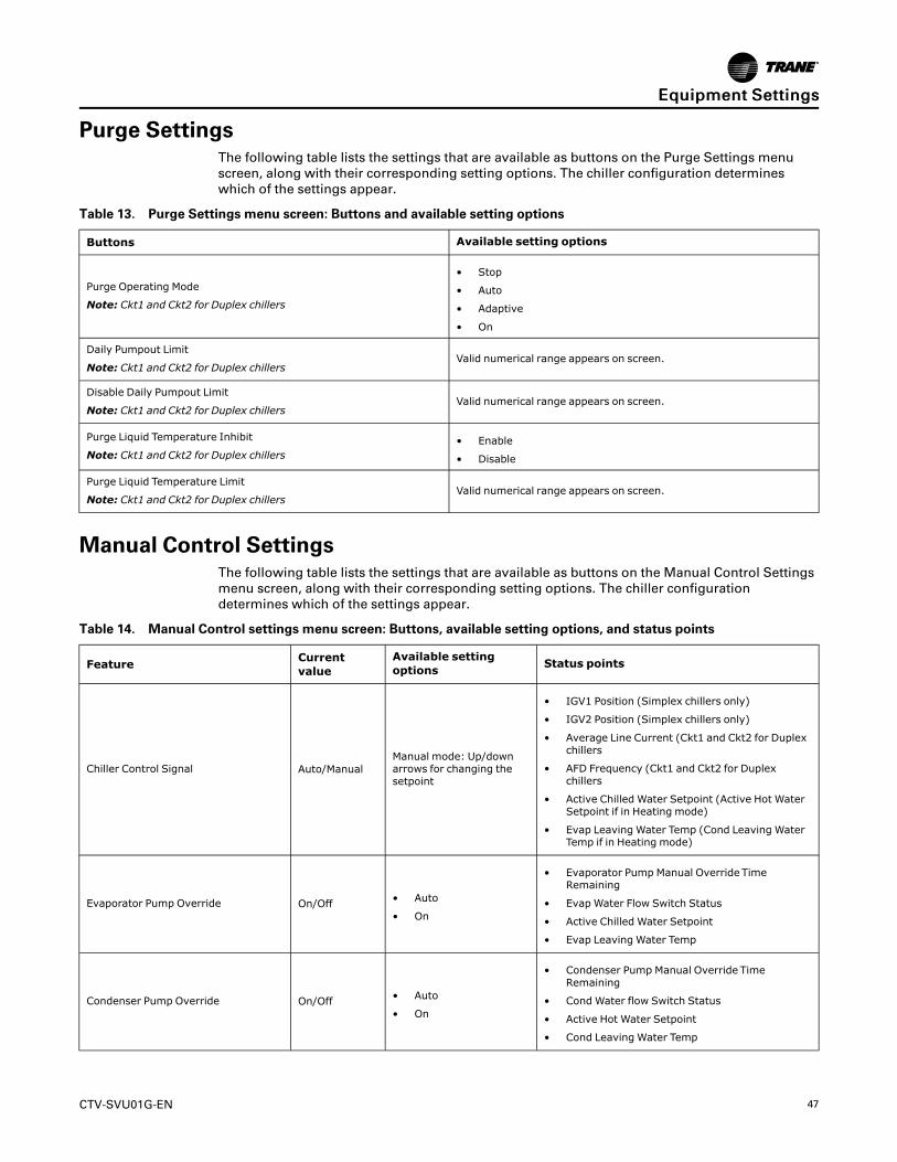
CTV-SVU01G-EN 47
Purge SettingsThe following table lists the settings that are available as buttons on the Purge Settings menuscreen, along with their corresponding setting options. The chiller configuration determineswhich of the settings appear.
Table 13. Purge Settings menu screen: Buttons and available setting options
Buttons Available setting options
Purge Operating Mode
Note: Ckt1 and Ckt2 for Duplex chillers
• Stop
• Auto
• Adaptive
• On
Daily Pumpout Limit
Note: Ckt1 and Ckt2 for Duplex chillersValid numerical range appears on screen.
Disable Daily Pumpout Limit
Note: Ckt1 and Ckt2 for Duplex chillersValid numerical range appears on screen.
Purge Liquid Temperature Inhibit
Note: Ckt1 and Ckt2 for Duplex chillers• Enable
• Disable
Purge Liquid Temperature Limit
Note: Ckt1 and Ckt2 for Duplex chillersValid numerical range appears on screen.
Manual Control SettingsThe following table lists the settings that are available as buttons on the Manual Control Settingsmenu screen, along with their corresponding setting options. The chiller configurationdetermines which of the settings appear.
Table 14. Manual Control settings menu screen: Buttons, available setting options, and status points
Feature Currentvalue
Available settingoptions Status points
Chiller Control Signal Auto/ManualManual mode: Up/downarrows for changing thesetpoint
• IGV1 Position (Simplex chillers only)
• IGV2 Position (Simplex chillers only)
• Average Line Current (Ckt1 and Ckt2 for Duplexchillers
• AFD Frequency (Ckt1 and Ckt2 for Duplexchillers
• Active Chilled Water Setpoint (Active Hot WaterSetpoint if in Heating mode)
• Evap Leaving Water Temp (Cond Leaving WaterTemp if in Heating mode)
Evaporator Pump Override On/Off • Auto
• On
• Evaporator Pump Manual Override TimeRemaining
• Evap Water Flow Switch Status
• Active Chilled Water Setpoint
• Evap Leaving Water Temp
Condenser Pump Override On/Off • Auto
• On
• Condenser Pump Manual Override TimeRemaining
• Cond Water flow Switch Status
• Active Hot Water Setpoint
• Cond Leaving Water Temp
EEqquuiippmmeenntt SSeettttiinnggss
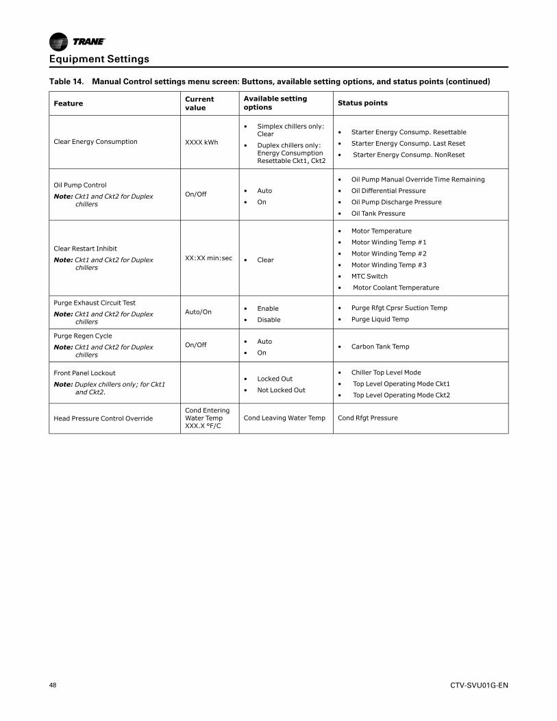
48 CTV-SVU01G-EN
Table 14. Manual Control settings menu screen: Buttons, available setting options, and status points (continued)
Feature Currentvalue
Available settingoptions Status points
Clear Energy Consumption XXXX kWh
• Simplex chillers only:Clear
• Duplex chillers only:Energy ConsumptionResettable Ckt1, Ckt2
• Starter Energy Consump. Resettable
• Starter Energy Consump. Last Reset
• Starter Energy Consump. NonReset
Oil Pump Control
Note: Ckt1 and Ckt2 for Duplexchillers
On/Off • Auto
• On
• Oil Pump Manual Override Time Remaining
• Oil Differential Pressure
• Oil Pump Discharge Pressure
• Oil Tank Pressure
Clear Restart Inhibit
Note: Ckt1 and Ckt2 for Duplexchillers
XX:XX min:sec • Clear
• Motor Temperature
• Motor Winding Temp #1
• Motor Winding Temp #2
• Motor Winding Temp #3
• MTC Switch
• Motor Coolant Temperature
Purge Exhaust Circuit Test
Note: Ckt1 and Ckt2 for Duplexchillers
Auto/On • Enable
• Disable
• Purge Rfgt Cprsr Suction Temp
• Purge Liquid Temp
Purge Regen Cycle
Note: Ckt1 and Ckt2 for Duplexchillers
On/Off • Auto
• On• Carbon Tank Temp
Front Panel Lockout
Note: Duplex chillers only; for Ckt1and Ckt2.
• Locked Out
• Not Locked Out
• Chiller Top Level Mode
• Top Level Operating Mode Ckt1
• Top Level Operating Mode Ckt2
Head Pressure Control OverrideCond EnteringWater TempXXX.X °F/C
Cond Leaving Water Temp Cond Rfgt Pressure
EEqquuiippmmeenntt SSeettttiinnggss

CTV-SVU01G-EN 49
Changing a Manual Control SettingTo change a manual control setting, follow this procedure:
1. In the Equipment Settings column on the Settings screen, touch MMaannuuaall CCoonnttrrooll SSeettttiinnggss.The Manual Control Settings screen appears as shown in the following figure.
Figure 27. Manual Control Settings screen
2. Touch the button that shows the manual control setting you want to change. A screen forchanging the manual control setting appears as shown in the following figure.
3. Touch the button that represents the setting you want. The button becomes shaded andAAppppllyy and SSaavvee buttons appear at the bottom of the screen.
NNoottee:: The Compressor Control Signal screen provides up/down arrow keys and numericalfields for selecting a value.
4. To save your change, do one of the following:
• Touch AAppppllyy. The change is communicated to the Tracer® UC800 controller. You canobserve the status points in the lower half of the screen change in response to the settingchange you just made. Also, a Manual Override button appears in the upper left corner ofthe screen (refer to the following figure).
• Touch SSaavvee. The change is communicated to the Tracer® UC800 controller. The screenyou were previously viewing appears.
EEqquuiippmmeenntt SSeettttiinnggss
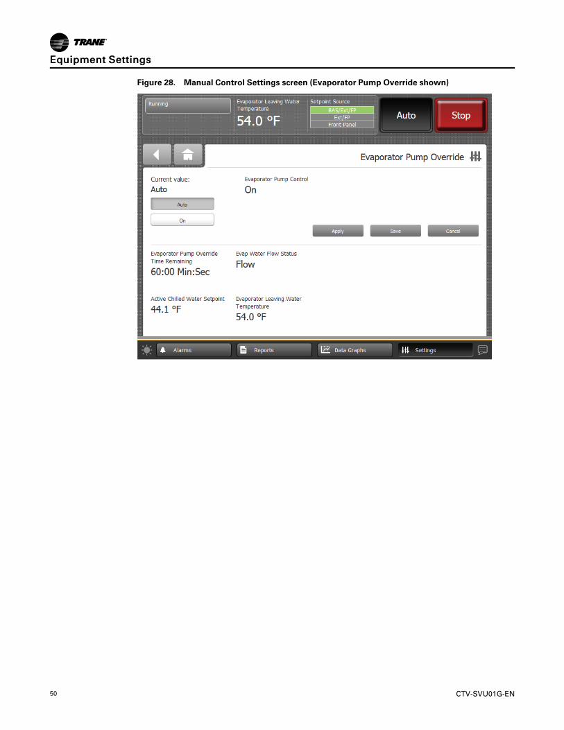
50 CTV-SVU01G-EN
Figure 28. Manual Control Settings screen (Evaporator Pump Override shown)
EEqquuiippmmeenntt SSeettttiinnggss
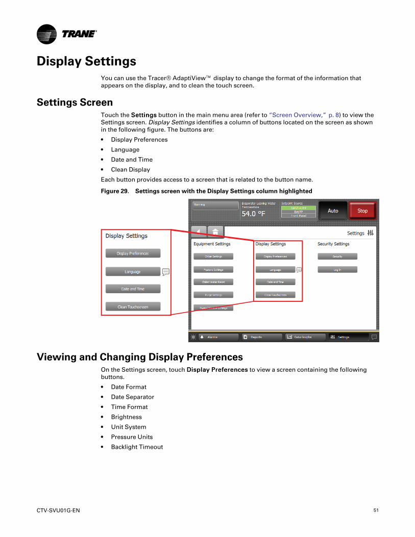
CTV-SVU01G-EN 51
Display SettingsYou can use the Tracer® AdaptiView™ display to change the format of the information thatappears on the display, and to clean the touch screen.
Settings ScreenTouch the SSeettttiinnggss button in the main menu area (refer to “Screen Overview,” p. 8) to view theSettings screen. Display Settings identifies a column of buttons located on the screen as shownin the following figure. The buttons are:
• Display Preferences
• Language
• Date and Time
• Clean Display
Each button provides access to a screen that is related to the button name.
Figure 29. Settings screen with the Display Settings column highlighted
Viewing and Changing Display PreferencesOn the Settings screen, touch DDiissppllaayy PPrreeffeerreenncceess to view a screen containing the followingbuttons.
• Date Format
• Date Separator
• Time Format
• Brightness
• Unit System
• Pressure Units
• Backlight Timeout

52 CTV-SVU01G-EN
Figure 30. Display Preferences screen
Each of the buttons in the previous figure shows the name of a display preference and its format(current value). Touch any of these buttons to view a screen where you can change the format.(Refer to the following figure for an example.) The button representing the format currently usedis shaded (see the “MMDDYYYY” button.
DDiissppllaayy SSeettttiinnggss

CTV-SVU01G-EN 53
Figure 31. Example of a display preference screen
To change the format:
1. Touch the button that shows that format you prefer.
2. Touch SSaavvee to confirm your selection and to return to the Display Preferences screen.
DDaattee FFoorrmmaattUse the Date Format screen to choose from the following date formats:
• MMDDYYYY (default)
• YYYYMMDD
• DDMMYYYY
DDaattee SSeeppaarraattoorrUse the Date Separator screen to choose from the following date formats:
• None
• Slash ( \ ) (default)
• Hyphen ( – )
• Period ( . )
• Underscore ( _ )
TTiimmee FFoorrmmaattUse the Time Format screen to choose from the following time formats:
• 12 hour (default)
• 24 hour
BBrriigghhttnneessssUse the numerical keypad on the Brightness screen to change the brightness of the screen. (Thedefault is 90%.)
DDiissppllaayy SSeettttiinnggss

54 CTV-SVU01G-EN
DDiissppllaayy UUnniittssUse the Display Units screen to choose from the following display units:
• SI
• Inch-Pounds (default)
PPrreessssuurree UUnniittssUse the Pressure Units screen to choose from the following pressure units:
• kPaA (default if “SI” is chosen for display units)
• kPaG
• psia (default if “Inch-Pound” is chosen for display units)
• psig
BBaacckklliigghhtt TTiimmeeoouuttUse the numerical keypad on the Backlight Timeout screen to change the number of minutes ofinactivity that pass until the screen dims. (The default is 60 minutes.)
Viewing and Changing the Language PreferenceOn the Settings screen, touch LLaanngguuaaggeess to view a screen containing the following buttons(refer to the following figure):
• Arabic (Gulf Regions)• Chinese—China• Chinese—Taiwan• Czech• Dutch• English• French• French (Canada)• German• Greek• Hebrew• Hungarian• Indonesian• Italian• Japanese• Korean• Norwegian• Polish• Portuguese (Portugal)• Portuguese (Brazil)• Russian• Romanian• Spanish (Europe)• Spanish (Latin America)• Swedish• Thai• Turkish
DDiissppllaayy SSeettttiinnggss
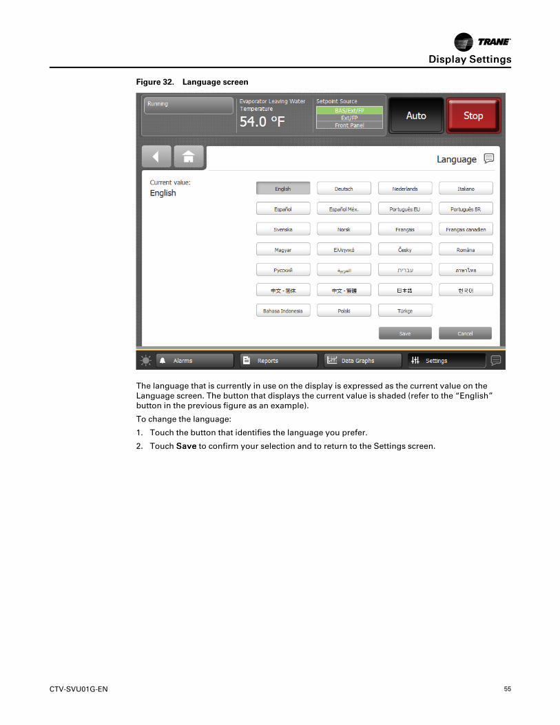
CTV-SVU01G-EN 55
Figure 32. Language screen
The language that is currently in use on the display is expressed as the current value on theLanguage screen. The button that displays the current value is shaded (refer to the “English”button in the previous figure as an example).
To change the language:
1. Touch the button that identifies the language you prefer.
2. Touch SSaavvee to confirm your selection and to return to the Settings screen.
DDiissppllaayy SSeettttiinnggss
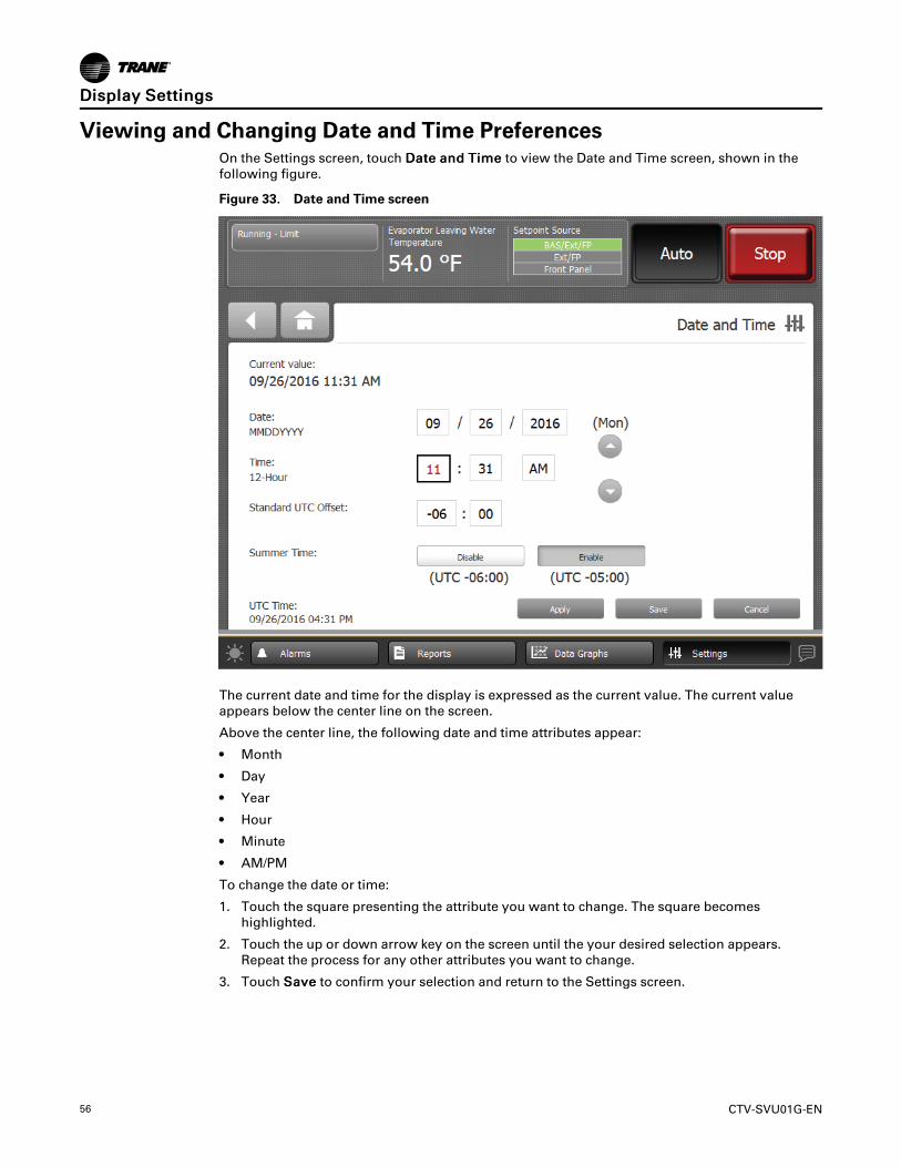
56 CTV-SVU01G-EN
Viewing and Changing Date and Time PreferencesOn the Settings screen, touch DDaattee aanndd TTiimmee to view the Date and Time screen, shown in thefollowing figure.
Figure 33. Date and Time screen
The current date and time for the display is expressed as the current value. The current valueappears below the center line on the screen.
Above the center line, the following date and time attributes appear:
• Month
• Day
• Year
• Hour
• Minute
• AM/PM
To change the date or time:
1. Touch the square presenting the attribute you want to change. The square becomeshighlighted.
2. Touch the up or down arrow key on the screen until the your desired selection appears.Repeat the process for any other attributes you want to change.
3. Touch SSaavvee to confirm your selection and return to the Settings screen.
DDiissppllaayy SSeettttiinnggss

CTV-SVU01G-EN 57
Clean TouchscreenOn the Settings screen, touch CClleeaann TToouucchhssccrreeeenn to disable the Tracer® AdaptiView™ displayscreen for 15 seconds so that you can clean the screen without it responding to touch. During thistime, the screen is black with a number in the center that counts down the seconds. After 15seconds, the Settings screen re-appears.
Figure 34. Countdown screen
DDiissppllaayy SSeettttiinnggss

58 CTV-SVU01G-EN
Security SettingsIf security if enabled, the Tracer® AdaptiView™ display requires that you log in with a four-digitsecurity PIN to make setting changes that are protected by security. This feature preventsunauthorized personnel from doing so. There are two levels of security, each allowing specificchanges to be made.
You can view all data without logging in. The log-in screen appears only when you try to changea setting that is protected by security, or when you touch the LLoogg iinn button from the Settingsscreen.
Settings ScreenTouch the SSeettttiinnggss button in the main menu area (refer to “Screen Overview,” p. 8) to view theSettings screen. Security Settings identifies a column on the right side of the screen that containstwo buttons (see the outlined column in the following figure):
• Security
• Log in (Log out)
Figure 35. Equipment Settings screen with the Security Settings column highlighted
NNoottee:: If security is disabled, the Log in/Log out button is not visible. Refer to “DisablingSecurity,” p. 58 and “Enabling Security,” p. 59.
Disabling SecurityYou can disable the security feature that allows a user to log in and log out.
1. From the Settings screen, touch the SSeeccuurriittyy button. The Security screen appears as shownin the following figure.
NNoottee:: If you are logged out, the Log In screen appears. You must first log in to proceed.

CTV-SVU01G-EN 59
Figure 36. Security screen
2. Touch the DDiissaabbllee button. The button becomes shaded.
3. Touch SSaavvee. The Settings screen appears with only the Security button visible. The Log in/Log out button is gone.
Enabling SecurityTo enable security, perform the following steps:
1. From the Settings screen, touch the SSeeccuurriittyy button. The Security screen appears as shownin “Disabling Security,” p. 58.
2. Touch the EEnnaabbllee button. The button becomes shaded.
3. Touch SSaavvee. The Settings screen appears with a Log out button in addition to the Securitybutton.
Logging InThere are two levels of security:
• Security Level 1 allows users to change a limited group of secure settings. The defaultsecurity PIN is 1111.
• Security Level 2 allows users to change all secure settings. The default security PIN is 7123.
A technician must use the Tracer® TU service tool to change a PIN.
To log in:
1. Touch the LLoogg IInn button. The Log In screen appears as shown in the following figure.
SSeeccuurriittyy SSeettttiinnggss

60 CTV-SVU01G-EN
Figure 37. Log In screen
2. Use the keypad to enter your PIN.
• The PIN is a four-digit number, which was configured for your system with the Tracer®TU service tool.
• As you enter the number, the PIN remains hidden by asterisks.
NNoottee:: If you enter an invalid PIN, an error message appears on the Log in screen.
3. Touch SSaavvee.
• If you viewed the Log In screen from touching LLoogg IInn on the Settings screen, the Settingsscreen appears with a LLoogg OOuutt button on it.
• If the Log In screen appeared when you tried to change a setting, you return to that settingscreen.
NNoottee:: The PIN is valid until 30 minutes of inactivity passes, or until you log out.
SSeeccuurriittyy SSeettttiinnggss

CTV-SVU01G-EN 61
Logging OutTo log out:
1. Touch the LLoogg OOuutt button. A confirmation screen appears as shown in the following figure.
Figure 38. Log Out confirmation screen
2. Touch YYeess to confirm that you want to log out. The Settings screen appears with a LLoogg IInnbutton on it.
LLID BindingLLID binding screen provides the capability to bind and unbind LLIDs, similar to Tracer® TU. Itcan be disabled in the configuration.
IImmppoorrttaanntt:: LLID binding screen should ONLY be used by experienced service personnel.
SSeeccuurriittyy SSeettttiinnggss
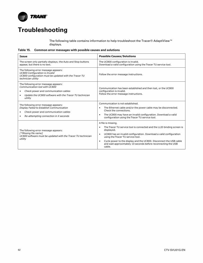
62 CTV-SVU01G-EN
Troubleshooting
The following table contains information to help troubleshoot the Tracer® AdaptiView™displays.
Table 15. Common error messages with possible causes and solutions
Issue Possible Causes/Solutions
The screen only partially displays; the Auto and Stop buttonsappear, but there is no text.
The UC800 configuration is invalid.Download a valid configuration using the Tracer TU service tool.
The following error message appears:UC800 Configuration is InvalidUC800 configuration must be updated with the Tracer TUtechnician utility
Follow the error message instructions.
The following error message appears:Communication lost with UC800
• Check power and communication cables
• Update the UC800 software with the Tracer TU technicianutility
Communication has been established and then lost, or the UC800configuration is invalid.Follow the error message instructions.
The following error message appears:Display Failed to Establish Communication
• Check power and communication cables
• Re-attempting connection in X seconds
Communication is not established.
• The Ethernet cable and/or the power cable may be disconnected.Check the connections.
• The UC800 may have an invalid configuration. Download a validconfiguration using the Tracer TU service tool.
The following error message appears:[*Missing file name]UC800 software must be updated with the Tracer TU technicianutility
A file is missing.
• The Tracer TU service tool is connected and the LLID binding screen isdisplayed.
• UC800 has an invalid configuration. Download a valid configurationusing the Tracer TU service tool.
• Cycle power to the display and the UC800. Disconnect the USB cableand wait approximately 10 seconds before reconnecting the USBcable.
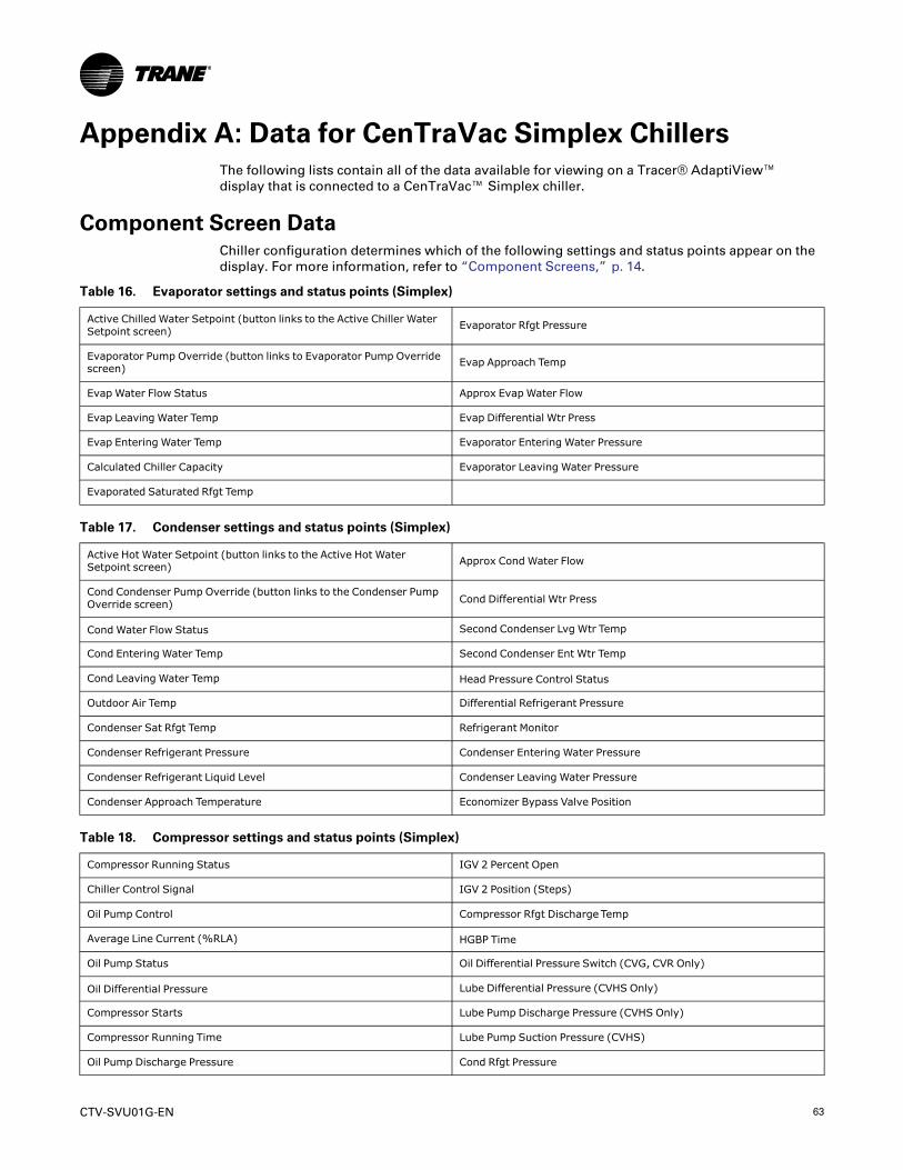
CTV-SVU01G-EN 63
Appendix A: Data for CenTraVac Simplex ChillersThe following lists contain all of the data available for viewing on a Tracer® AdaptiView™display that is connected to a CenTraVac™ Simplex chiller.
Component Screen DataChiller configuration determines which of the following settings and status points appear on thedisplay. For more information, refer to “Component Screens,” p. 14.
Table 16. Evaporator settings and status points (Simplex)
Active Chilled Water Setpoint (button links to the Active Chiller WaterSetpoint screen) Evaporator Rfgt Pressure
Evaporator Pump Override (button links to Evaporator Pump Overridescreen) Evap Approach Temp
Evap Water Flow Status Approx Evap Water Flow
Evap Leaving Water Temp Evap Differential Wtr Press
Evap Entering Water Temp Evaporator Entering Water Pressure
Calculated Chiller Capacity Evaporator Leaving Water Pressure
Evaporated Saturated Rfgt Temp
Table 17. Condenser settings and status points (Simplex)
Active Hot Water Setpoint (button links to the Active Hot WaterSetpoint screen) Approx Cond Water Flow
Cond Condenser Pump Override (button links to the Condenser PumpOverride screen) Cond Differential Wtr Press
Cond Water Flow Status Second Condenser Lvg Wtr Temp
Cond Entering Water Temp Second Condenser Ent Wtr Temp
Cond Leaving Water Temp Head Pressure Control Status
Outdoor Air Temp Differential Refrigerant Pressure
Condenser Sat Rfgt Temp Refrigerant Monitor
Condenser Refrigerant Pressure Condenser Entering Water Pressure
Condenser Refrigerant Liquid Level Condenser Leaving Water Pressure
Condenser Approach Temperature Economizer Bypass Valve Position
Table 18. Compressor settings and status points (Simplex)
Compressor Running Status IGV 2 Percent Open
Chiller Control Signal IGV 2 Position (Steps)
Oil Pump Control Compressor Rfgt Discharge Temp
Average Line Current (%RLA) HGBP Time
Oil Pump Status Oil Differential Pressure Switch (CVG, CVR Only)
Oil Differential Pressure Lube Differential Pressure (CVHS Only)
Compressor Starts Lube Pump Discharge Pressure (CVHS Only)
Compressor Running Time Lube Pump Suction Pressure (CVHS)
Oil Pump Discharge Pressure Cond Rfgt Pressure
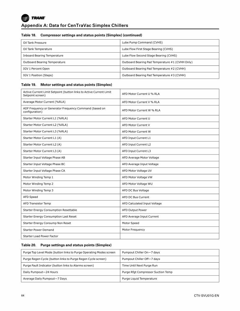
64 CTV-SVU01G-EN
Table 18. Compressor settings and status points (Simplex) (continued)
Oil Tank Pressure Lube Pump Command (CVHS)
Oil Tank Temperature Lube Flow First Stage Bearing (CVHS)
Inboard Bearing Temperature Lube Flow Second Stage Bearing (CVHS)
Outboard Bearing Temperature Outboard Bearing Pad Temperature #1 (CVHH Only)
IGV 1 Percent Open Outboard Bearing Pad Temperature #2 (CVHH)
IGV 1 Position (Steps) Outboard Bearing Pad Temperature #3 (CVHH)
Table 19. Motor settings and status points (Simplex)
Active Current Limit Setpoint (button links to Active Current LimitSetpoint screen) AFD Motor Current U% RLA
Average Motor Current (%RLA) AFD Motor Current V % RLA
ADF Frequency or Generator Frequency Command (based onconfiguration) AFD Motor Current W% RLA
Starter Motor Current L1 (%RLA) AFD Motor Current U
Starter Motor Current L2 (%RLA) AFD Motor Current V
Starter Motor Current L3 (%RLA) AFD Motor Current W
Starter Motor Current L1 (A) AFD Input Current L1
Starter Motor Current L2 (A) AFD Input Current L2
Starter Motor Current L3 (A) AFD Input Current L3
Starter Input Voltage Phase AB AFD Average Motor Voltage
Starter Input Voltage Phase BC AFD Average Input Voltage
Starter Input Voltage Phase CA AFD Motor Voltage UV
Motor Winding Temp 1 AFD Motor Voltage VW
Motor Winding Temp 2 AFD Motor Voltage WU
Motor Winding Temp 3 AFD DC Bus Voltage
AFD Speed AFD DC Bus Current
AFD Transistor Temp AFD Calculated Input Voltage
Starter Energy Consumption Resettable AFD Output Power
Starter Energy Consumption Last Reset AFD Average Input Current
Starter Energy Consump Non Reset Motor Speed
Starter Power Demand Motor Frequency
Starter Load Power Factor
Table 20. Purge settings and status points (Simplex)
Purge Top Level Mode (button links to Purge Operating Modes screen Pumpout Chiller On—7 days
Purge Regen Cycle (button links to Purge Regen Cycle screen) Pumpout Chiller Off—7 days
Purge Fault Indicator (button links to Alarms screen) Time Until Next Purge Run
Daily Pumpout—24 Hours Purge Rfgt Compressor Suction Temp
Average Daily Pumpout—7 Days Purge Liquid Temperature
AAppppeennddiixx AA:: DDaattaa ffoorr CCeennTTrraaVVaacc SSiimmpplleexx CChhiilllleerrss
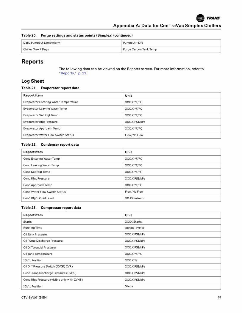
CTV-SVU01G-EN 65
Table 20. Purge settings and status points (Simplex) (continued)
Daily Pumpout Limit/Alarm Pumpout—Life
Chiller On—7 Days Purge Carbon Tank Temp
ReportsThe following data can be viewed on the Reports screen. For more information, refer to“Reports,” p. 23.
Log SheetTable 21. Evaporator report data
Report item Unit
Evaporator Entering Water Temperature XXX.X °F/°C
Evaporator Leaving Water Temp XXX.X °F/°C
Evaporator Sat Rfgt Temp XXX.X °F/°C
Evaporator Rfgt Pressure XXX.X PSI/kPa
Evaporator Approach Temp XXX.X °F/°C
Evaporator Water Flow Switch Status Flow/No Flow
Table 22. Condenser report data
Report item Unit
Cond Entering Water Temp XXX.X °F/°C
Cond Leaving Water Temp XXX.X °F/°C
Cond Sat Rfgt Temp XXX.X °F/°C
Cond Rfgt Pressure XXX.X PSI/kPa
Cond Approach Temp XXX.X °F/°C
Cond Water Flow Switch Status Flow/No Flow
Cond Rfgt Liquid Level XX.XX in/mm
Table 23. Compressor report data
Report item Unit
Starts XXXX Starts
Running Time XX:XX Hr:Min
Oil Tank Pressure XXX.X PSI/kPa
Oil Pump Discharge Pressure XXX.X PSI/kPa
Oil Differential Pressure XXX.X PSI/kPa
Oil Tank Temperature XXX.X °F/°C
IGV 1 Position XXX.X %
Oil Diff Pressure Switch (CVGF, CVR) XXX.X PSI/kPa
Lube Pump Discharge Pressure (CVHS) XXX.X PSI/kPa
Cond Rfgt Pressure (visible only with CVHS) XXX.X PSI/kPa
IGV 1 Position Steps
AAppppeennddiixx AA:: DDaattaa ffoorr CCeennTTrraaVVaacc SSiimmpplleexx CChhiilllleerrss
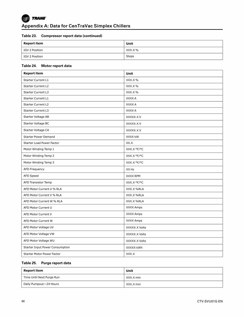
66 CTV-SVU01G-EN
Table 23. Compressor report data (continued)
Report item Unit
IGV 2 Position XXX.X %
IGV 2 Position Steps
Table 24. Motor report data
Report item Unit
Starter Current L1 XXX.X %
Starter Current L2 XXX.X %
Starter Current L3 XXX.X %
Starter Current L1 XXXX A
Starter Current L2 XXXX A
Starter Current L3 XXXX A
Starter Voltage AB XXXXX.X V
Starter Voltage BC XXXXX.X V
Starter Voltage CA XXXXX.X V
Starter Power Demand XXXX kW
Starter Load Power Factor XX.X
Motor Winding Temp 1 XXX.X °F/°C
Motor Winding Temp 2 XXX.X °F/°C
Motor Winding Temp 3 XXX.X °F/°C
AFD Frequency XX Hz
AFD Speed XXXX RPM
AFD Transistor Temp XXX.X °F/°C
AFD Motor Current U% RLA XXX.X %RLA
AFD Motor Current V % RLA XXX.X %RLA
AFD Motor Current W% RLA XXX.X %RLA
AFD Motor Current U XXXX Amps
AFD Motor Current V XXXX Amps
AFD Motor Current W XXXX Amps
AFD Motor Voltage UV XXXXX.X Volts
AFD Motor Voltage VW XXXXX.X Volts
AFD Motor Voltage WU XXXXX.X Volts
Starter Input Power Consumption XXXXX kWh
Starter Motor Power Factor XXX.X
Table 25. Purge report data
Report item Unit
Time Until Next Purge Run XXX.X min
Daily Pumpout—24 Hours XXX.X min
AAppppeennddiixx AA:: DDaattaa ffoorr CCeennTTrraaVVaacc SSiimmpplleexx CChhiilllleerrss
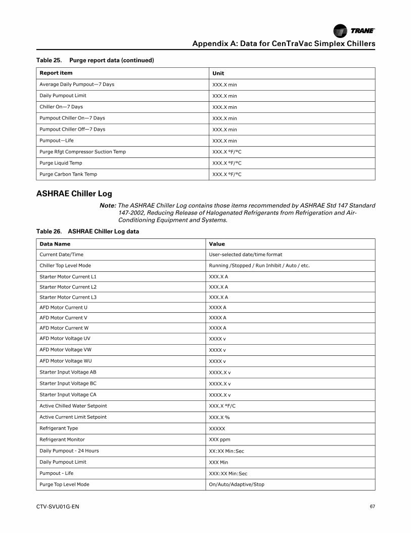
CTV-SVU01G-EN 67
Table 25. Purge report data (continued)
Report item Unit
Average Daily Pumpout—7 Days XXX.X min
Daily Pumpout Limit XXX.X min
Chiller On—7 Days XXX.X min
Pumpout Chiller On—7 Days XXX.X min
Pumpout Chiller Off—7 Days XXX.X min
Pumpout—Life XXX.X min
Purge Rfgt Compressor Suction Temp XXX.X °F/°C
Purge Liquid Temp XXX.X °F/°C
Purge Carbon Tank Temp XXX.X °F/°C
ASHRAE Chiller LogNNoottee:: The ASHRAE Chiller Log contains those items recommended by ASHRAE Std 147 Standard
147-2002, Reducing Release of Halogenated Refrigerants from Refrigeration and Air-Conditioning Equipment and Systems.
Table 26. ASHRAE Chiller Log data
Data Name Value
Current Date/Time User-selected date/time format
Chiller Top Level Mode Running /Stopped / Run Inhibit / Auto / etc.
Starter Motor Current L1 XXX.X A
Starter Motor Current L2 XXX.X A
Starter Motor Current L3 XXX.X A
AFD Motor Current U XXXX A
AFD Motor Current V XXXX A
AFD Motor Current W XXXX A
AFD Motor Voltage UV XXXX v
AFD Motor Voltage VW XXXX v
AFD Motor Voltage WU XXXX v
Starter Input Voltage AB XXXX.X v
Starter Input Voltage BC XXXX.X v
Starter Input Voltage CA XXXX.X v
Active Chilled Water Setpoint XXX.X °F/C
Active Current Limit Setpoint XXX.X %
Refrigerant Type XXXXX
Refrigerant Monitor XXX ppm
Daily Pumpout - 24 Hours XX:XX Min:Sec
Daily Pumpout Limit XXX Min
Pumpout - Life XXX:XX Min:Sec
Purge Top Level Mode On/Auto/Adaptive/Stop
AAppppeennddiixx AA:: DDaattaa ffoorr CCeennTTrraaVVaacc SSiimmpplleexx CChhiilllleerrss

68 CTV-SVU01G-EN
Table 26. ASHRAE Chiller Log data (continued)
Data Name Value
Purge Mode On/Auto/Adaptive/Stop
Compressor Starts XXXX
Compressor Running Time XX:XX Hr:Min
Compressor Refrigerant Discharge Temperature* XXX.X °F/C
Oil Pump Discharge Pressure XXX.X PSIA/kPaA
Oil Tank Pressure XXX.X PSIA/kPaA
Oil Differential Pressure XXX.XX PSID/kPaD
Oil Diff Pressure Switch(CVGF, CVR only) Flow/No Flow
Lube Pump Discharge Pressure(CVHS) XXX.X PSIA/kPaA
Cond Rfgt Pressure(visible only with CVHS) XXX.X PSIA/kPaA
Lube Differential Pressure(CVHS) XXX.XX PSID/kPaD
Lube Pump Suction Pressure(CVHS) XXX.X PSIA/kPaA
Oil Tank Temperature XXX.X °F/C
Inboard Bearing Temp XXX.X °F/C
Outboard Bearing Temp XXX.X °F/C
Daily Pumpout - 24 Hours XX:XX Min:Sec
Daily Pumpout Limit XXX Min
Pumpout - Life XXX:XX Min:Sec
Purge Top Level Mode On/Auto/Adaptive/Stop
Purge Mode On/Auto/Adaptive/Stop
Compressor Starts XXXX
Compressor Running Time XX:XX Hr:Min
Compressor Refrigerant Discharge Temperature* XXX.X °F/C
Oil Pump Discharge Pressure XXX.X PSIA/kPaA
Oil Tank Pressure XXX.X PSIA/kPaA
Oil Differential Pressure XXX.XX PSID/kPaD
Oil Diff Pressure Switch(CVGF, CVR only) Flow/No Flow
Lube Pump Discharge Pressure(CVHS) XXX.X PSIA/kPaA
Cond Rfgt Pressure(visible only with CVHS) XXX.X PSIA/kPaA
Lube Differential Pressure(CVHS) XXX.XX PSID/kPaD
Lube Pump Suction Pressure(CVHS) XXX.X PSIA/kPaA
Oil Tank Temperature XXX.X °F/C
AAppppeennddiixx AA:: DDaattaa ffoorr CCeennTTrraaVVaacc SSiimmpplleexx CChhiilllleerrss
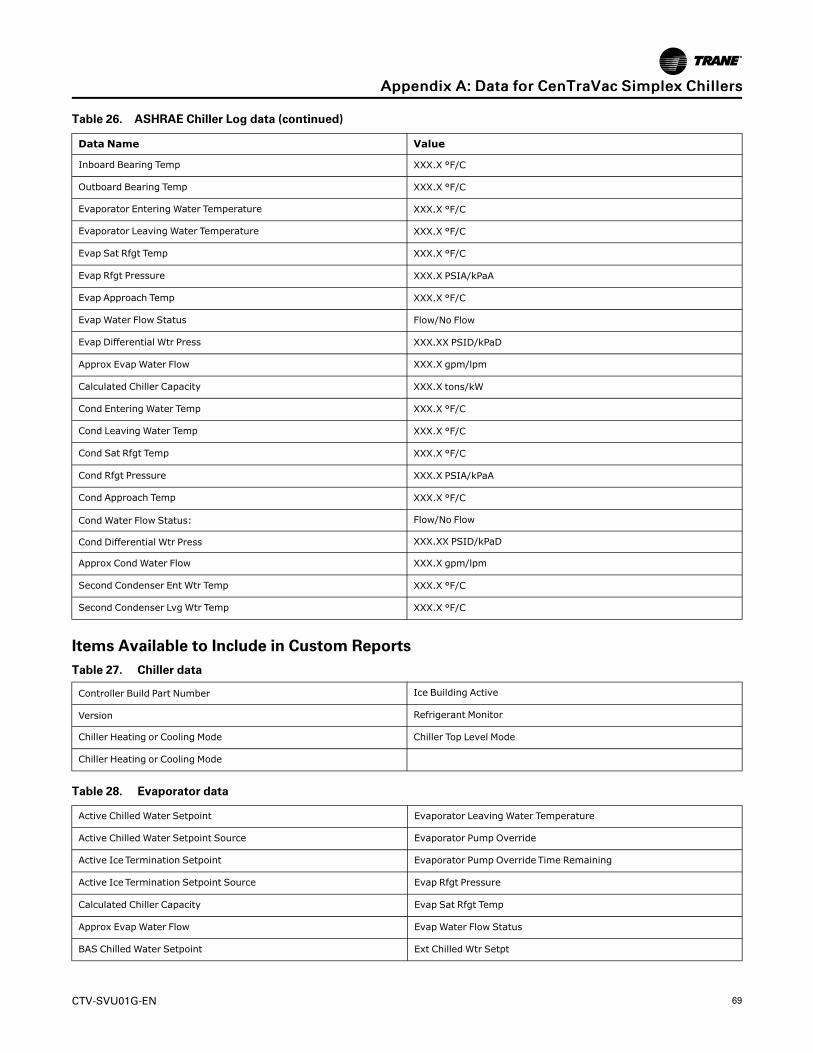
CTV-SVU01G-EN 69
Table 26. ASHRAE Chiller Log data (continued)
Data Name Value
Inboard Bearing Temp XXX.X °F/C
Outboard Bearing Temp XXX.X °F/C
Evaporator Entering Water Temperature XXX.X °F/C
Evaporator Leaving Water Temperature XXX.X °F/C
Evap Sat Rfgt Temp XXX.X °F/C
Evap Rfgt Pressure XXX.X PSIA/kPaA
Evap Approach Temp XXX.X °F/C
Evap Water Flow Status Flow/No Flow
Evap Differential Wtr Press XXX.XX PSID/kPaD
Approx Evap Water Flow XXX.X gpm/lpm
Calculated Chiller Capacity XXX.X tons/kW
Cond Entering Water Temp XXX.X °F/C
Cond Leaving Water Temp XXX.X °F/C
Cond Sat Rfgt Temp XXX.X °F/C
Cond Rfgt Pressure XXX.X PSIA/kPaA
Cond Approach Temp XXX.X °F/C
Cond Water Flow Status: Flow/No Flow
Cond Differential Wtr Press XXX.XX PSID/kPaD
Approx Cond Water Flow XXX.X gpm/lpm
Second Condenser Ent Wtr Temp XXX.X °F/C
Second Condenser Lvg Wtr Temp XXX.X °F/C
Items Available to Include in Custom ReportsTable 27. Chiller data
Controller Build Part Number Ice Building Active
Version Refrigerant Monitor
Chiller Heating or Cooling Mode Chiller Top Level Mode
Chiller Heating or Cooling Mode
Table 28. Evaporator data
Active Chilled Water Setpoint Evaporator Leaving Water Temperature
Active Chilled Water Setpoint Source Evaporator Pump Override
Active Ice Termination Setpoint Evaporator Pump Override Time Remaining
Active Ice Termination Setpoint Source Evap Rfgt Pressure
Calculated Chiller Capacity Evap Sat Rfgt Temp
Approx Evap Water Flow Evap Water Flow Status
BAS Chilled Water Setpoint Ext Chilled Wtr Setpt
AAppppeennddiixx AA:: DDaattaa ffoorr CCeennTTrraaVVaacc SSiimmpplleexx CChhiilllleerrss

70 CTV-SVU01G-EN
Table 28. Evaporator data (continued)
Evap Approach Temp Front Panel Ice Building Command
Evap Differential Wtr Press Evaporator Entering Water Pressure
Evaporator Entering Water Temperature Evaporator Leaving Water Pressure
Table 29. Condenser data
Active Hot Water Setpoint Second Condenser Lvg Wtr Temp
Active Hot Water Setpoint Source Condenser Pump Override Time Remaining
Approx Cond Water Flow Condenser Pump Override
Cond Approach Temp Differential Refrigerant Pressure
Cond Differential Wtr Press Head Pressure Control Status
Cond Entering Water Temp Condenser Entering Water Pressure
Cond Leaving Water Temp Condenser Leaving Water Pressure
Cond Rfgt Pressure Condenser Refrigerant Liquid Level Ckt1
Cond Sat Rfgt Temp Economizer Bypass Valve Position Ckt1
Cond Water Flow Status Condenser Refrigerant Liquid Level Ckt2
Outdoor Air Temp Economizer Bypass Valve Position Ckt2
Second Condenser Ent Wtr Temp
Table 30. Compressor data
Chiller Control Signal Oil Pump Control
Active Base Loading Setpoint Oil Pump Command
Active Base Loading Setpoint Source Oil Pump Discharge Pressure
Compressor Refrigerant Discharge Temperature Oil Pump Override Time Remaining
Compressor Running Lube Differential Pressure(CVHS)
Compressor Running Time Lube Pump Control(CVHS)
Compressor Starts Lube Pump Command(CVHS)
Hot Gas Bypass Total Time Lube Pump Discharge Pressure(CVHS)
IGV1 PositionLube Pump Override Time Remaining(CVHS)
IGV1 Position Steps Lube Pump Suction Pressure(CVHS)
IGV2 Position Oil Tank Temperature
IGV2 Position Steps Lube Flow First Stage Bearing(CVHS)
IGV Closed SwitchLube Flow Second Stage Bearing(CVHS)
Oil Tank Pressure Inboard Bearing Temp
Oil Differential Pressure Outboard Bearing Temp
AAppppeennddiixx AA:: DDaattaa ffoorr CCeennTTrraaVVaacc SSiimmpplleexx CChhiilllleerrss
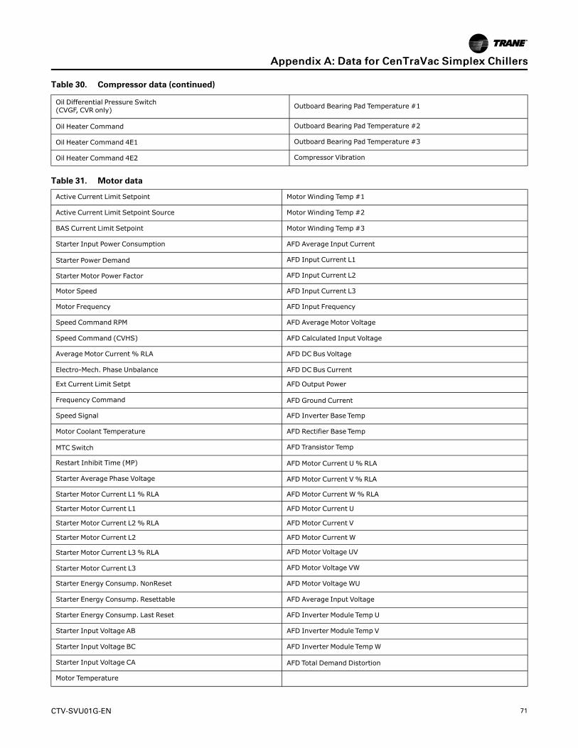
CTV-SVU01G-EN 71
Table 30. Compressor data (continued)
Oil Differential Pressure Switch(CVGF, CVR only) Outboard Bearing Pad Temperature #1
Oil Heater Command Outboard Bearing Pad Temperature #2
Oil Heater Command 4E1 Outboard Bearing Pad Temperature #3
Oil Heater Command 4E2 Compressor Vibration
Table 31. Motor data
Active Current Limit Setpoint Motor Winding Temp #1
Active Current Limit Setpoint Source Motor Winding Temp #2
BAS Current Limit Setpoint Motor Winding Temp #3
Starter Input Power Consumption AFD Average Input Current
Starter Power Demand AFD Input Current L1
Starter Motor Power Factor AFD Input Current L2
Motor Speed AFD Input Current L3
Motor Frequency AFD Input Frequency
Speed Command RPM AFD Average Motor Voltage
Speed Command (CVHS) AFD Calculated Input Voltage
Average Motor Current % RLA AFD DC Bus Voltage
Electro-Mech. Phase Unbalance AFD DC Bus Current
Ext Current Limit Setpt AFD Output Power
Frequency Command AFD Ground Current
Speed Signal AFD Inverter Base Temp
Motor Coolant Temperature AFD Rectifier Base Temp
MTC Switch AFD Transistor Temp
Restart Inhibit Time (MP) AFD Motor Current U% RLA
Starter Average Phase Voltage AFD Motor Current V% RLA
Starter Motor Current L1% RLA AFD Motor Current W% RLA
Starter Motor Current L1 AFD Motor Current U
Starter Motor Current L2% RLA AFD Motor Current V
Starter Motor Current L2 AFD Motor Current W
Starter Motor Current L3% RLA AFD Motor Voltage UV
Starter Motor Current L3 AFD Motor Voltage VW
Starter Energy Consump. NonReset AFD Motor Voltage WU
Starter Energy Consump. Resettable AFD Average Input Voltage
Starter Energy Consump. Last Reset AFD Inverter Module Temp U
Starter Input Voltage AB AFD Inverter Module Temp V
Starter Input Voltage BC AFD Inverter Module TempW
Starter Input Voltage CA AFD Total Demand Distortion
Motor Temperature
AAppppeennddiixx AA:: DDaattaa ffoorr CCeennTTrraaVVaacc SSiimmpplleexx CChhiilllleerrss

72 CTV-SVU01G-EN
Table 32. Purge data
Average Daily Pumpout-7 Days Carbon Tank Temp
Carbon Regen Cycles Purge Liquid Temp
Chiller On-7 Days Purge Rfgt Cprsr Suction Temp
Daily Pumpout-24 Hours Time at Last Regeneration
Pumpout Chiller Off-7 Days Time Until Next Purge Run
Pumpout Chiller On-7 Days Purge Top Level Mode
Pumpout-Life
Data Graph Data PointsThis subsection contains:
• Data points used in the default data graphs, organized by graph
• Data points available to include in custom data graphs, organized by component
Data Points Used in Default Data GraphsTable 33. Chiller overview 1
Graph data point Axis
Active Chilled Water Setpoint Left Y-axis
Active Hot Water Setpoint Left Y-axis
Evaporator Leaving Evaporator Temperature Left Y-axis
Evaporator Entering Water Temperature Left Y-axis
Condenser Leaving Water Temperature Left Y-axis
Condenser Entering Water Temperature Left Y-axis
Calculated Chiller Capacity Right Y-axis
Table 34. Chiller overview 2
Graph data point Axis
Average Motor Current % RLA Left Y-axis
Motor Frequency Left Y-axis
Oil Differential Pressure Left Y-axis
Frequency Command Left Y-axis
Lube Differential Pressure(CVHS) Left Y-axis
Speed Command(CVHS) Right Y-axis
Table 35. Approach temperature
Graph data point Axis
Evaporator Approach Temperature Left Y-axis
Condenser Approach Temperature Left Y-axis
Approximate Evaporator Water Flow Right Y-axis
AAppppeennddiixx AA:: DDaattaa ffoorr CCeennTTrraaVVaacc SSiimmpplleexx CChhiilllleerrss
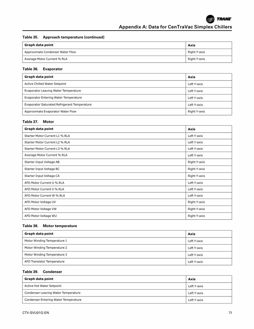
CTV-SVU01G-EN 73
Table 35. Approach temperature (continued)
Graph data point Axis
Approximate Condenser Water Flow Right Y-axis
Average Motor Current % RLA Right Y-axis
Table 36. Evaporator
Graph data point Axis
Active Chilled Water Setpoint Left Y-axis
Evaporator Leaving Water Temperature Left Y-axis
Evaporator Entering Water Temperature Left Y-axis
Evaporator Saturated Refrigerant Temperature Left Y-axis
Approximate Evaporator Water Flow Right Y-axis
Table 37. Motor
Graph data point Axis
Starter Motor Current L1% RLA Left Y-axis
Starter Motor Current L2% RLA Left Y-axis
Starter Motor Current L3% RLA Left Y-axis
Average Motor Current % RLA Left Y-axis
Starter Input Voltage AB Right Y-axis
Starter Input Voltage BC Right Y-axis
Starter Input Voltage CA Right Y-axis
AFD Motor Current U% RLA Left Y-axis
AFD Motor Current V % RLA Left Y-axis
AFD Motor Current W% RLA Left Y-axis
AFD Motor Voltage UV Right Y-axis
AFD Motor Voltage VW Right Y-axis
AFD Motor Voltage WU Right Y-axis
Table 38. Motor temperature
Graph data point Axis
Motor Winding Temperature 1 Left Y-axis
Motor Winding Temperature 2 Left Y-axis
Motor Winding Temperature 3 Left Y-axis
AFD Transistor Temperature Left Y-axis
Table 39. Condenser
Graph data point Axis
Active Hot Water Setpoint Left Y-axis
Condenser Leaving Water Temperature Left Y-axis
Condenser Entering Water Temperature Left Y-axis
AAppppeennddiixx AA:: DDaattaa ffoorr CCeennTTrraaVVaacc SSiimmpplleexx CChhiilllleerrss

74 CTV-SVU01G-EN
Table 39. Condenser (continued)
Graph data point Axis
Condenser Saturated Refrigerant Temperature Left Y-axis
Approximate Condenser Water Flow Right Y-axis
Table 40. Compressor
Graph data point Axis
Average Line Current Left Y-axis
Active Current Limit Setpoint Left Y-axis
AFD Frequency Left Y-axis
IGV 1 Position Left Y-axis
Chiller Control Signal Left Y-axis
Compressor Refrigerant Discharge Temperature Right Y-axis
Table 41. Purge
Graph data point Axis
Daily Pumpout—24 Hours Left Y-axis
Pumpout Chiller On—7 Days Left Y-axis
Pumpout Chiller Off—7 Days Left Y-axis
Purge Average Daily Pumpout—7 Days Right Y-axis
Purge Refrigerant Compressor Suction Temperature Right Y-axis
Purge Liquid Temperature Right Y-axis
Table 42. Oil system
Graph data point Axis
Oil Differential Pressure Left Y-axis
Oil Tank Pressure Left Y-axis
Oil Pump Discharge Pressure Left Y-axis
Oil Tank Temperature Right Y-axis
Outboard Bearing Temperature Right Y-axis
Inboard Bearing Temperature Right Y-axis
Table 43. Lube system
Graph data point Axis
Lube Differential Pressure Left Y-axis
Lube Pump Discharge Pressure Left Y-axis
Cond Rfgt Pressure Left Y-axis
Lube Pump Suction Pressure Left Y-axis
Lube Flow First Stage Bearing Right Y-axis
Lube Flow Second Stage Bearing Right Y-axis
AAppppeennddiixx AA:: DDaattaa ffoorr CCeennTTrraaVVaacc SSiimmpplleexx CChhiilllleerrss

CTV-SVU01G-EN 75
Data Points in Custom Data GraphsTable 44. Evaporator
Active Chilled Water Setpoint Approx Evap Water Flow
Evaporator Leaving Water Temperature Evap Differential Wtr Press
Evaporator Entering Water Temperature Calculated Chiller Capacity
Evap Sat Rfgt Temp Evap Approach Temp
Evap Rfgt Pressure Active Ice Termination Setpoint
Table 45. Compressor
Chiller Control Signal Inboard Bearing Temp
Oil Tank Pressure Outboard Bearing Temp
Oil Pump Discharge Pressure Outboard Bearing Pad Temperature #1
Oil Differential Pressure Outboard Bearing Pad Temperature #2
Lube Pump Suction Pressure(CVHS) Outboard Bearing Pad Temperature #3
Lube Pump Discharge Pressure(CVHS) IGV1 Position (%)
Lube Differential Pressure(CVHS) IGV2 Position (%)
Oil Tank Temperature Compressor Refrigerant Discharge Temperature
Lube Flow First Stage Bearing(CVHS) Compressor Vibration
Lube Flow Second Stage Bearing(CVHS)
Table 46. Condenser
Active Hot Water Setpoint Cond Approach Temp
Cond Leaving Water Temp Approx Cond Water Flow
Cond Entering Water Temp Cond Differential Wtr Press
Cond Sat Rfgt Temp Second Condenser Lvg Wtr Temp
Outdoor Air Temp Second Condenser Ent Wtr Temp
Refrigerant Monitor Differential Refrigerant Pressure
Cond Rfgt Pressure Head Pressure Control Status
Table 47. Motor
Active Current Limit Setpoint AFD Input Current L1
Average Motor Current %RLA AFD Input Current L2
Motor Frequency AFD Input Current L3
Speed Command(CVHS) AFD Input Frequency
Starter Motor Current L1% RLA AFD Average Motor Voltage
Starter Motor Current L2% RLA AFD DC Bus Voltage
Starter Motor Current L3% RLA AFD DC Bus Current
AAppppeennddiixx AA:: DDaattaa ffoorr CCeennTTrraaVVaacc SSiimmpplleexx CChhiilllleerrss
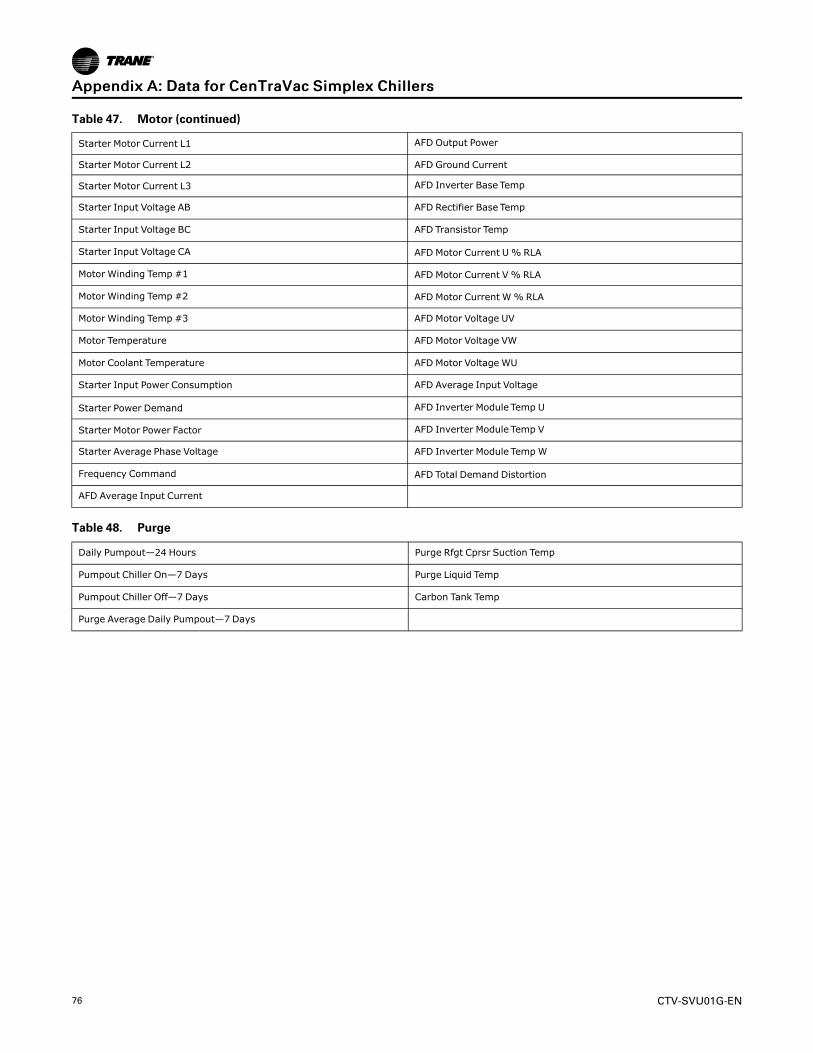
76 CTV-SVU01G-EN
Table 47. Motor (continued)
Starter Motor Current L1 AFD Output Power
Starter Motor Current L2 AFD Ground Current
Starter Motor Current L3 AFD Inverter Base Temp
Starter Input Voltage AB AFD Rectifier Base Temp
Starter Input Voltage BC AFD Transistor Temp
Starter Input Voltage CA AFD Motor Current U% RLA
Motor Winding Temp #1 AFD Motor Current V % RLA
Motor Winding Temp #2 AFD Motor Current W% RLA
Motor Winding Temp #3 AFD Motor Voltage UV
Motor Temperature AFD Motor Voltage VW
Motor Coolant Temperature AFD Motor Voltage WU
Starter Input Power Consumption AFD Average Input Voltage
Starter Power Demand AFD Inverter Module Temp U
Starter Motor Power Factor AFD Inverter Module Temp V
Starter Average Phase Voltage AFD Inverter Module Temp W
Frequency Command AFD Total Demand Distortion
AFD Average Input Current
Table 48. Purge
Daily Pumpout—24 Hours Purge Rfgt Cprsr Suction Temp
Pumpout Chiller On—7 Days Purge Liquid Temp
Pumpout Chiller Off—7 Days Carbon Tank Temp
Purge Average Daily Pumpout—7 Days
AAppppeennddiixx AA:: DDaattaa ffoorr CCeennTTrraaVVaacc SSiimmpplleexx CChhiilllleerrss
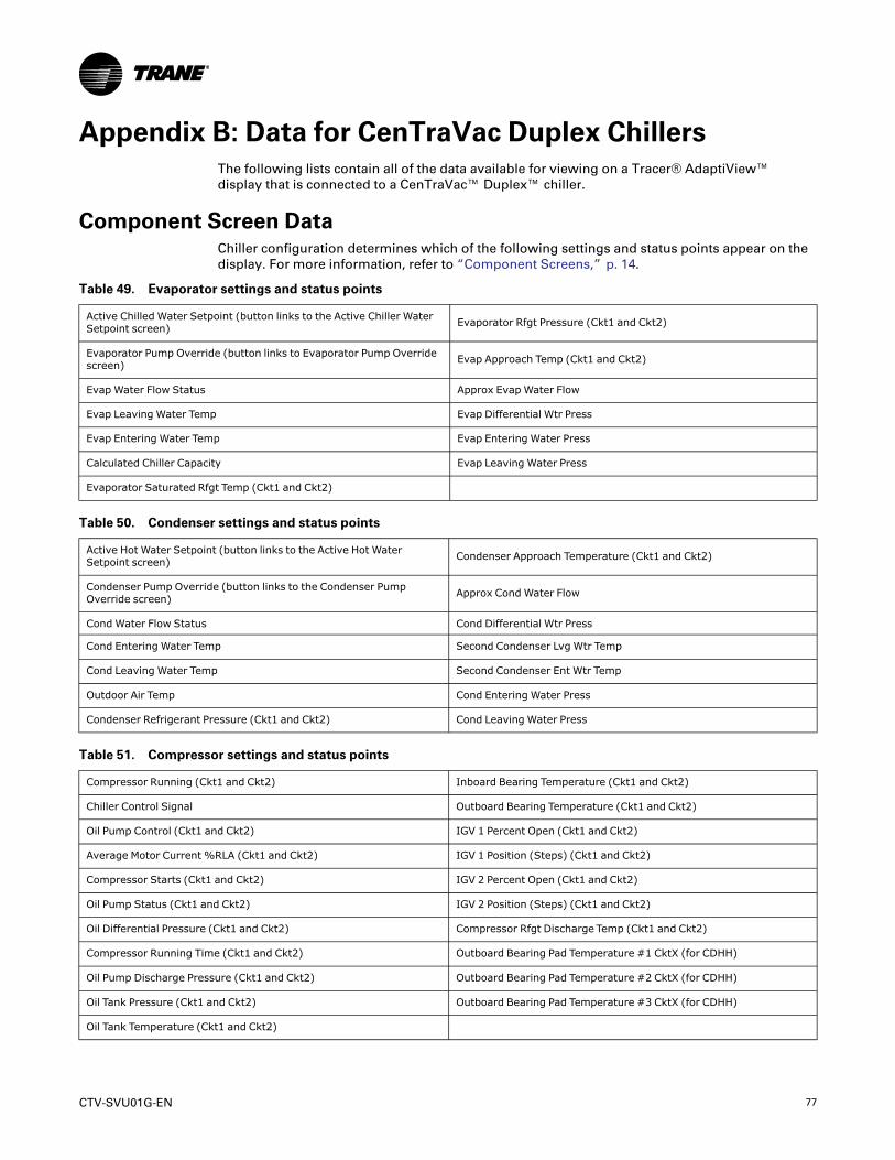
CTV-SVU01G-EN 77
Appendix B: Data for CenTraVac Duplex ChillersThe following lists contain all of the data available for viewing on a Tracer® AdaptiView™display that is connected to a CenTraVac™ Duplex™ chiller.
Component Screen DataChiller configuration determines which of the following settings and status points appear on thedisplay. For more information, refer to “Component Screens,” p. 14.
Table 49. Evaporator settings and status points
Active Chilled Water Setpoint (button links to the Active Chiller WaterSetpoint screen) Evaporator Rfgt Pressure (Ckt1 and Ckt2)
Evaporator Pump Override (button links to Evaporator Pump Overridescreen) Evap Approach Temp (Ckt1 and Ckt2)
Evap Water Flow Status Approx Evap Water Flow
Evap Leaving Water Temp Evap Differential Wtr Press
Evap Entering Water Temp Evap Entering Water Press
Calculated Chiller Capacity Evap Leaving Water Press
Evaporator Saturated Rfgt Temp (Ckt1 and Ckt2)
Table 50. Condenser settings and status points
Active Hot Water Setpoint (button links to the Active Hot WaterSetpoint screen) Condenser Approach Temperature (Ckt1 and Ckt2)
Condenser Pump Override (button links to the Condenser PumpOverride screen) Approx Cond Water Flow
Cond Water Flow Status Cond Differential Wtr Press
Cond Entering Water Temp Second Condenser Lvg Wtr Temp
Cond Leaving Water Temp Second Condenser Ent Wtr Temp
Outdoor Air Temp Cond Entering Water Press
Condenser Refrigerant Pressure (Ckt1 and Ckt2) Cond Leaving Water Press
Table 51. Compressor settings and status points
Compressor Running (Ckt1 and Ckt2) Inboard Bearing Temperature (Ckt1 and Ckt2)
Chiller Control Signal Outboard Bearing Temperature (Ckt1 and Ckt2)
Oil Pump Control (Ckt1 and Ckt2) IGV 1 Percent Open (Ckt1 and Ckt2)
Average Motor Current %RLA (Ckt1 and Ckt2) IGV 1 Position (Steps) (Ckt1 and Ckt2)
Compressor Starts (Ckt1 and Ckt2) IGV 2 Percent Open (Ckt1 and Ckt2)
Oil Pump Status (Ckt1 and Ckt2) IGV 2 Position (Steps) (Ckt1 and Ckt2)
Oil Differential Pressure (Ckt1 and Ckt2) Compressor Rfgt Discharge Temp (Ckt1 and Ckt2)
Compressor Running Time (Ckt1 and Ckt2) Outboard Bearing Pad Temperature #1 CktX (for CDHH)
Oil Pump Discharge Pressure (Ckt1 and Ckt2) Outboard Bearing Pad Temperature #2 CktX (for CDHH)
Oil Tank Pressure (Ckt1 and Ckt2) Outboard Bearing Pad Temperature #3 CktX (for CDHH)
Oil Tank Temperature (Ckt1 and Ckt2)
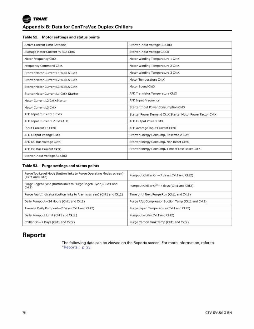
78 CTV-SVU01G-EN
Table 52. Motor settings and status points
Active Current Limit Setpoint Starter Input Voltage BC CktX
Average Motor Current % RLA CktX Starter Input Voltage CA Ck
Motor Frequency CktX Motor Winding Temperature 1 CktX
Frequency Command CktX Motor Winding Temperature 2 CktX
Starter Motor Current L1% RLA CktX Motor Winding Temperature 3 CktX
Starter Motor Current L2% RLA CktX Motor Temperature CktX
Starter Motor Current L3% RLA CktX Motor Speed CktX
Starter Motor Current L1 CktX Starter AFD Transistor Temperature CktX
Motor Current L2 CktXStarter AFD Input Frequency
Motor Current L3 CktX Starter Input Power Consumption CktX
AFD Input Current L1 CktX Starter Power Demand CktX Starter Motor Power Factor CktX
AFD Input Current L2 CktXAFD AFD Output Power CktX
Input Current L3 CktX AFD Average Input Current CktX
AFD Output Voltage CktX Starter Energy Consump. Resettable CktX
AFD DC Bus Voltage CktX Starter Energy Consump. Non Reset CktX
AFD DC Bus Current CktX Starter Energy Consump. Time of Last Reset CktX
Starter Input Voltage AB CktX
Table 53. Purge settings and status points
Purge Top Level Mode (button links to Purge Operating Modes screen)(Ckt1 and Ckt2) Pumpout Chiller On—7 days (Ckt1 and Ckt2)
Purge Regen Cycle (button links to PUrge Regen Cycle) (Ckt1 andCkt2) Pumpout Chiller Off—7 days (Ckt1 and Ckt2)
Purge Fault Indicator (button links to Alarms screen) (Ckt1 and Ckt2) Time Until Next Purge Run (Ckt1 and Ckt2)
Daily Pumpout—24 Hours (Ckt1 and Ckt2) Purge Rfgt Compressor Suction Temp (Ckt1 and Ckt2)
Average Daily Pumpout—7 Days (Ckt1 and Ckt2) Purge Liquid Temperature (Ckt1 and Ckt2)
Daily Pumpout Limit (Ckt1 and Ckt2) Pumpout—Life (Ckt1 and Ckt2)
Chiller On—7 Days (Ckt1 and Ckt2) Purge Carbon Tank Temp (Ckt1 and Ckt2)
ReportsThe following data can be viewed on the Reports screen. For more information, refer to“Reports,” p. 23.
AAppppeennddiixx BB:: DDaattaa ffoorr CCeennTTrraaVVaacc DDuupplleexx CChhiilllleerrss

CTV-SVU01G-EN 79
Log SheetTable 54. Evaporator
Report item Unit
Evaporator Entering Water Temperature XXX.X °F/°C
Evaporator Leaving Water Temp XXX.X °F/°C
Evaporator Water Flow Status Flow/No Flow
Evaporator Sat Rfgt Temp (Ckt1 and Ckt2) XXX.X °F/°C
Evaporator Rfgt Pressure (Ckt1 and Ckt2) XXX.X PSI/kPa
Evaporator Approach Temp (Ckt1 and Ckt2) XXX.X °F/°C
Table 55. Condenser
Report item Unit
Cond Entering Water Temp Cond Entering Water Temp
Cond Leaving Water Temp Cond Leaving Water Temp
Cond Water Flow Status Cond Water Flow Status
Cond Sat Rfgt Temp (Ckt1 and Ckt2) Cond Sat Rfgt Temp (Ckt1 and Ckt2)
Cond Rfgt Pressure (Ckt1 and Ckt2) Cond Rfgt Pressure (Ckt1 and Ckt2)
Cond Approach Temp (Ckt1 and Ckt2) Cond Approach Temp (Ckt1 and Ckt2)
Table 56. Motor
Report item Unit
Starter Current L1 %RLA (Ckt1 and Ckt2) XXX.X %
Starter Current L2 %RLA (Ckt1 and Ckt2) XXX.X %
Compressor Starts (Ckt1 and Ckt2) XXXX Starts
Compressor Running Time (Ckt1 and Ckt2) XX:XX Hr:Min
Oil Tank Pressure (Ckt1 and Ckt2) XXX.X PSI/kPa
Oil Pump Discharge Pressure (Ckt1 and Ckt2) XXX.X PSI/kPa
Oil Differential Pressure (Ckt1 and Ckt2) XXX.X PSI/kPa
Oil Tank Temperature (Ckt1 and Ckt2) XXX.X °F/°C
IGV 1 Percent Open (Ckt1 and Ckt2) XXX.X %
IGV 1 Position (Ckt1 and Ckt2) Steps
IGV 2 Percent Open (Ckt1 and Ckt2) XXX.X %
IGV 2 Position (Ckt1 and Ckt2) Steps
Starter Current L3 %RLA (Ckt1 and Ckt2) XXX.X %
Starter Current L1 (Ckt1 and Ckt2) XXXX A
Starter Current L2 (Ckt1 and Ckt2) XXXX A
Starter Current L3 (Ckt1 and Ckt2) XXXX A
Starter Voltage Phase AB (Ckt1 and Ckt2) XXXXX.X V
Starter Voltage Phase BC (Ckt1 and Ckt2) XXXXX.X V
Starter Voltage Phase CA (Ckt1 and Ckt2) XXXXX.X V
AAppppeennddiixx BB:: DDaattaa ffoorr CCeennTTrraaVVaacc DDuupplleexx CChhiilllleerrss

80 CTV-SVU01G-EN
Table 56. Motor (continued)
Report item Unit
Starter Power Demand (Ckt1 and Ckt2) XXXX kW
Starter Load Power Factor (Ckt1 and Ckt2) XX.X
Motor Winding Temp 1 (Ckt1 and Ckt2) XXX.X °F/°C
Motor Winding Temp 2 (Ckt1 and Ckt2) XXX.X °F/°C
Motor Winding Temp 3 (Ckt1 and Ckt2) XXX.X °F/°C
AFD Frequency (Ckt1 and Ckt2) XX Hz
AFD Speed (Ckt1 and Ckt2) XXXX RPM
AFD Transistor Temp (Ckt1 and Ckt2) XXX.X °F/°C
Table 57. Purge
Report item Unit
Time Until Next Purge Run (Ckt1 and Ckt2) XXX.X min
Daily Pumpout—24 Hours (Ckt1 and Ckt2) XXX.X min
Average Daily Pumpout—7 Days (Ckt1 and Ckt2) XXX.X min
Daily Pumpout Limit (Ckt1 and Ckt2) XXX.X min
Chiller On—7 Days (Ckt1 and Ckt2) XXX.X min
Pumpout Chiller On—7 Days (Ckt1 and Ckt2) XXX.X min
Pumpout Chiller Off—7 Days (Ckt1 and Ckt2) XXX.X min
Pumpout—Life (Ckt1 and Ckt2) XXX.X min
Purge Rfgt Compressor Suction Temp (Ckt1 and Ckt2) XXX.X °F/°C
Purge Liquid Temp (Ckt1 and Ckt2) XXX.X °F/°C
Purge Carbon Tank Temp (Ckt1 and Ckt2) XXX.X °F/°C
ASHRAE Chiller LogNNoottee:: The ASHRAE Chiller Log contains those items recommended by ASHRAE Std 147 Standard
147-2002, Reducing Release of Halogenated Refrigerants from Refrigeration and Air-Conditioning Equipment and Systems.
Table 58. ASHRAE Chiller Log data
Data name Value
Current Date/Time User-selected date/time format
Chiller Top Level Mode Dependent on chiller type
Evap Entering Water Temp XXX.X °F/C°
Evap Leaving Water Temp XXX.X °F/C°
Evap Water Flow Status Flow/No Flow
Evap Differential Wtr Press XXX.X PSI/kPa
Approx Evap Water Flow XXX.X gpm/lpm
Calculated Chiller Capacity XXXX tons/kW
Refrigerant Type R123
AAppppeennddiixx BB:: DDaattaa ffoorr CCeennTTrraaVVaacc DDuupplleexx CChhiilllleerrss

CTV-SVU01G-EN 81
Table 58. ASHRAE Chiller Log data (continued)
Data name Value
Refrigerant Monitor XXX.X ppm
Active Chilled Water Setpoint XXX.X F°/C°
Active Current Limit Setpoint XXX.X %
Cond Entering Water Temp XXX.X °F/C°
Cond Leaving Water Temp XXX.X °F/C°
Cond Water Flow Status Flow/No Flow
Cond Differential Wtr Press XXX.X PSI/kPa
Approx Cond Water Flow XXXX gpm/lpm
Top Level Operating Mode (Ckt1 and Ckt2) Dependent on chiller type
Evaporator Saturated Rfgt Temp (Ckt1 and Ckt2) XXX.X °F/C°
Evaporator Refrigerant Pressure (Ckt1 and Ckt2) XXX.X PSI/kPa
Evaporator Approach Temp (Ckt1 and Ckt2) XXX.X °F/C°
Condenser Saturated Rfgt Temp (Ckt1 and Ckt2) XXX.X °F/C°
Condenser Refrigerant Pressure (Ckt1 and Ckt2) XXX.X PSI/kPa
Condenser Approach Temperature (Ckt1 and Ckt2) XXX.X °F/C°
Compressor Starts (Ckt1 and Ckt2) XXXX
Compressor Running Time (Ckt1 and Ckt2) XX:XX Hr:Min
Compressor Refrigerant Discharge Temperature (Ckt1 and Ckt2) XXX.X °F/C°
Oil Pump Discharge Pressure (Ckt1 and Ckt2) XXX.X PSI/kPa
Oil Tank Pressure (Ckt1 and Ckt2) XXX.X PSI/kPa
Oil Differential Pressure (Ckt1 and Ckt2) XXX.X PSI/kPa
Oil Tank Temperature (Ckt1 and Ckt2) XXX.X °F/C°
Inboard Bearing Temp (Ckt1 and Ckt2) XXX.X °F/C°
Outboard Bearing Temp (Ckt1 and Ckt2) XXX.X F°/C°
Daily Pumpout—24 Hrs (Ckt1 and Ckt2) XXX.X Min
Daily Pumpout Limit (Ckt1 and Ckt2) XXX.X Min
Pumpout—Life (Ckt1 and Ckt2) XXXXXX.X Hours
Purge Top Level Mode (Ckt1 and Ckt2) On/Auto/Adaptive/Stop
Purge Operating Mode (Ckt1 and Ckt2) On/Auto/Adaptive/Stop
Starter Current L1 (Ckt1 and Ckt2) XXXX A
Starter Current L2 (Ckt1 and Ckt2) XXXX A
Starter Current L3 (Ckt1 and Ckt2) XXXX A
Starter Voltage Phase AB (Ckt1 and Ckt2) XXXX V
Starter Voltage Phase BC (Ckt1 and Ckt2) XXXX V
Starter Voltage Phase CA (Ckt1 and Ckt2) XXXX V
AAppppeennddiixx BB:: DDaattaa ffoorr CCeennTTrraaVVaacc DDuupplleexx CChhiilllleerrss

82 CTV-SVU01G-EN
Items Available to Include in Custom ReportsTable 59. Chiller
Active Base Loading Setpoint Version
Active Base Loading Setpoint Source Chiller Heating or Cooling Mode
Application Part Number Chiller Top Level Mode
Table 60. Evaporator
Active Chilled Water Setpoint Evaporator Saturated Refrigerant Temperature (Ckt1 and Ckt2)
Active Chilled Water Setpoint Source Evaporator Water Flow Status
BAS Chilled Water Setpoint Active Ice Termination Setpoint
Evaporator Approach Temperature (Ckt1 and Ckt2) Active Ice Termination Setpoint Source
Evaporator Entering Water Temperature Calculated Chiller Capacity
Evaporator Leaving Water Temperature Approx EvapWater Flow
Evaporator Pump Override Evap Differential Wtr Pressure
Evaporator Pump Override Time Remaining External Chilled Water Setpoint
Evaporator Refrigerant Pressure (Ckt1 and Ckt2) Front Panel Ice Building Command
Table 61. Compressor
Chiller Control Signal Oil Differential Pressure (Ckt1 and Ckt2)
Active Base Loading Setpoint Oil Heater Command (Ckt1 and Ckt2)
Active Base Loading Setpoint Source Oil Pump Control (Ckt1 and Ckt2)
Compressor Refrigerant Discharge Temperature (Ckt1 and Ckt2) Oil Pump Command (Ckt1 and Ckt2)
Compressor Running Status (Ckt1 and Ckt2) Oil Pump Discharge Pressure (Ckt1 and Ckt2)
Compressor Running Time (Ckt1 and Ckt2) Oil Pump Override Time Remaining
Compressor Starts (Ckt1 and Ckt2) Oil Tank Pressure (Ckt1 and Ckt2)
Inboard Bearing Temperature (Ckt1 and Ckt2) Oil Tank Temperature (Ckt1 and Ckt2)
IGV1 Position (Ckt1 and Ckt2) Oil Pump Override Time Remaining (Ckt1 and Ckt2)
IGV1 Percent Open (Ckt1 and Ckt2) Outboard Bearing Temperature (Ckt1 and Ckt2)
IGV2 Position (Ckt1 and Ckt2) Inboard Bearing Temperature (Ckt1 and Ckt2)
IGV2 Percent Open (Ckt1 and Ckt2)
Table 62. Condenser
Condenser Approach Temperature (Ckt1 and Ckt2) Condenser Pump Override
Condenser Entering Water Temperature (Ckt1 and Ckt2) Active Hot Water Setpoint
Condenser Leaving Water Temperature (Ckt1 and Ckt2) Active Hot Water Setpoint Source
Condenser Refrigerant Pressure (Ckt1 and Ckt2) Approx Cond Water Flow
Condenser Saturated Refrigerant Temperature (Ckt1 and Ckt2) Cond Differential Wtr Press
Condenser Water Flow Status Outdoor Air Temperature
Condenser Pump Override Time Remaining
AAppppeennddiixx BB:: DDaattaa ffoorr CCeennTTrraaVVaacc DDuupplleexx CChhiilllleerrss

CTV-SVU01G-EN 83
Table 63. Motor
Active Current Limit Setpoint Phase Unbalance (Ckt1 and Ckt2)
Active Current Limit Setpoint Source Restart Inhibit Time (MP) (Ckt1 and Ckt2)
BAS Current Limit Setpoint Starter Average Phase Voltage (Ckt1 and Ckt2)
External Current Limit Setpoint Starter Current L1%RLA (Ckt1 and Ckt2)
AFD DC Bus Voltage (Ckt1 and Ckt2) Starter Current L1 (Ckt1 and Ckt2)
AFD Output Power (Ckt1 and Ckt2) Starter Current L2%RLA (Ckt1 and Ckt2)
AFD Transistor Temperature (Ckt1 and Ckt2) Starter Current L2 (Ckt1 and Ckt2)
Starter Power Consumption (Ckt1 and Ckt2) Starter Current L3%RLA (Ckt1 and Ckt2)
Starter Load Power Factor (Ckt1 and Ckt2) Starter Current L3 (Ckt1 and Ckt2)
Speed (Ckt1 and Ckt2) Starter Energy Consumption Not Resettable (Ckt1 and Ckt2)
Frequency (Ckt1 and Ckt2) Starter Energy Consumption Resettable (Ckt1 and Ckt2)
Generator Frequency Command (Ckt1 and Ckt2) Starter Energy Consumption Last Reset (Ckt1 and Ckt2)
Generator Speed Signal (Ckt1 and Ckt2) Starter Power Demand (Ckt1 and Ckt2)
Average Line Current %RLA (Ckt1 and Ckt2) Starter Voltage Phase AB (Ckt1 and Ckt2)
Motor Winding Temperature 1 (Ckt1 and Ckt2) Starter Voltage Phase BC (Ckt1 and Ckt2)
Motor Winding Temperature 2 (Ckt1 and Ckt2) Starter Voltage Phase CA (Ckt1 and Ckt2)
Motor Winding Temperature 3 (Ckt1 and Ckt2)
Table 64. Purge
Purge Top Level Mode (Ckt1 and Ckt2) Pumpout—Life (Ckt1 and Ckt2)
Average Daily Pumpout—7 Days (Ckt1 and Ckt2) Purge Carbon Tank Temp (Ckt1 and Ckt2)
Carbon Regen Cycles (Ckt1 and Ckt2) Purge Liquid Temperature (Ckt1 and Ckt2)
Chiller On—7 Days (Ckt1 and Ckt2) Purge Refrigerant Compressor Suction Temp (Ckt1 and Ckt2)
Daily Pumpout—24 Hours (Ckt1 and Ckt2) Time at Last Regeneration (Ckt1 and Ckt2)
Pumpout Chiller Off—7 Days (Ckt1 and Ckt2) Time Until Next Purge Run (Ckt1 and Ckt2)
Pumpout Chiller On—7 Days (Ckt1 and Ckt2)
Data Graph Data PointsThis subsection contains:
• Data points used in the default data graphs, organized by graph
• Data points available to include in custom data graphs, organized by component
Data Points Used in Default Data GraphsTable 65. Chiller Overview 1
Graph data point Axis
Active Chilled Water Setpoint Left Y-axis
Active Hot Water Setpoint Left Y-axis
Evaporator Leaving Evaporator Temperature Left Y-axis
Evaporator Entering Water Temperature Left Y-axis
AAppppeennddiixx BB:: DDaattaa ffoorr CCeennTTrraaVVaacc DDuupplleexx CChhiilllleerrss

84 CTV-SVU01G-EN
Table 65. Chiller Overview 1 (continued)
Graph data point Axis
Condenser Leaving Water Temperature Left Y-axis
Condenser Entering Water Temperature Left Y-axis
Calculated Chiller Capacity Right Y-axis
Table 66. Chiller Overview 2
Graph data point Axis
Average Motor Current % RLA Ckt1 1st y-axis Left Y-axis
Average Motor Current % RLA Ckt2 1st y-axis Left Y-axis
Motor Frequency Ckt1 1st y-axis Left Y-axis
Motor Frequency Ckt2 1st y-axis Left Y-axis
Oil Differential Pressure Ckt1 1st y-axis Left Y-axis
Oil Differential Pressure Ckt2 1st y-axis Left Y-axis
Table 67. Evaporator
Graph data point Axis
Active Chilled Water Setpoint Left Y-axis
Evaporator Leaving Water Temperature Left Y-axis
Evaporator Entering Water Temperature Left Y-axis
Evaporator Saturated Refrigerant Temperature (Ckt1 and Ckt2) Left Y-axis
Approximate Evaporator Water Flow Right Y-axis
Table 68. Condenser
Graph data point Axis
Active Hot Water Setpoint Left Y-axis
Condenser Leaving Water Temperature Left Y-axis
Condenser Entering Water Temperature Left Y-axis
Condenser Saturated Refrigerant Temperature (Ckt1 and Ckt2) Left Y-axis
Approximate Condenser Water Flow Right Y-axis
Table 69. Compressor
Graph data point Axis
Average Motor Current % RLA (Ckt1 and Ckt2) Left Y-axis
Active Current Limit Setpoint Left Y-axis
AFD Frequency (Ckt1 and Ckt2) Left Y-axis
IGV 1 Percent Open (Ckt1 and Ckt2) Left Y-axis
Chiller Control Signal (Ckt1 and Ckt2) Left Y-axis
Compressor Refrigerant Discharge Temperature (Ckt1 and Ckt2) Right Y-axis
AAppppeennddiixx BB:: DDaattaa ffoorr CCeennTTrraaVVaacc DDuupplleexx CChhiilllleerrss

CTV-SVU01G-EN 85
Table 70. Oil System
Graph data point Axis
Oil Differential Pressure (Ckt1 and Ckt2) Left Y-axis
Oil Tank Pressure (Ckt1 and Ckt2) Left Y-axis
Oil Pump Discharge Pressure (Ckt1 and Ckt2) Left Y-axis
Oil Tank Temperature (Ckt1 and Ckt2) Right Y-axis
Outboard Bearing Temperature (Ckt1 and Ckt2) Right Y-axis
Inboard Bearing Temperature (Ckt1 and Ckt2) Right Y-axis
Table 71. Oil System
Graph data point Axis
Oil Differential Pressure (Ckt1 and Ckt2) Left Y-axis
Oil Tank Pressure (Ckt1 and Ckt2) Left Y-axis
Oil Pump Discharge Pressure (Ckt1 and Ckt2) Left Y-axis
Oil Tank Temperature (Ckt1 and Ckt2) Right Y-axis
Outboard Bearing Temperature (Ckt1 and Ckt2) Right Y-axis
Inboard Bearing Temperature (Ckt1 and Ckt2) Right Y-axis
Table 72. Motor
Graph data point Axis
Average Motor Current %RLA CktX Left Y-axis
Starter Motor Current L1% RLA CktX Left Y-axis
Starter Motor Current L2% RLA (CktX) Left Y-axis
Starter Motor Current L3% RLA (CktX) Left Y-axis
Starter Input Voltage Phase AB (CktX) Right Y-axis
Starter Input Voltage Phase BC (CktX) Right Y-axis
Starter Input Voltage Phase CA (CktX) Right Y-axis
Table 73. Motor Temperature
Graph data point Axis
Motor Winding Temperature 1 (Ckt1 and Ckt2) Left Y-axis
Motor Winding Temperature 2 (Ckt1 and Ckt2) Left Y-axis
Motor Winding Temperature 3 (Ckt1 and Ckt2) Left Y-axis
AFD Transistor Temperature (Ckt1 and Ckt2) Left Y-axis
Table 74. Purge
Graph data point Axis
Daily Pumpout—24 Hours (Ckt1 and Ckt2) Left Y-axis
Pumpout Chiller On—7 Days (Ckt1 and Ckt2) Left Y-axis
Pumpout Chiller Off—7 Days (Ckt1 and Ckt2) Left Y-axis
AAppppeennddiixx BB:: DDaattaa ffoorr CCeennTTrraaVVaacc DDuupplleexx CChhiilllleerrss
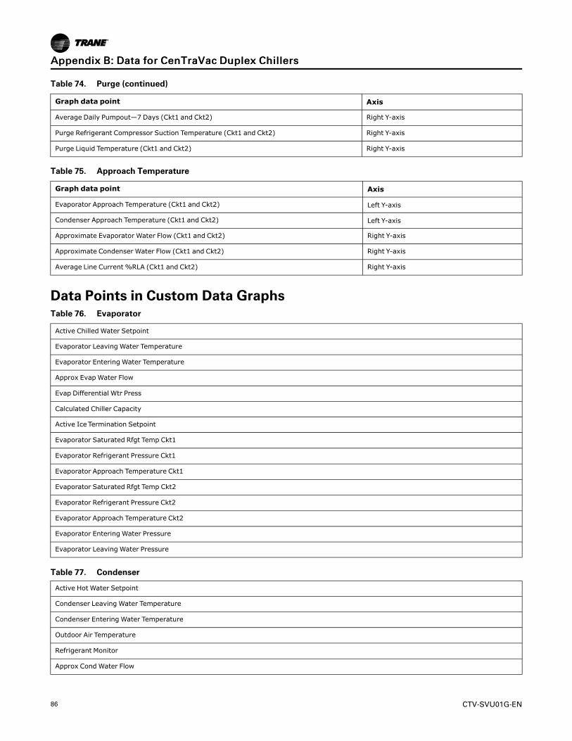
86 CTV-SVU01G-EN
Table 74. Purge (continued)
Graph data point Axis
Average Daily Pumpout—7 Days (Ckt1 and Ckt2) Right Y-axis
Purge Refrigerant Compressor Suction Temperature (Ckt1 and Ckt2) Right Y-axis
Purge Liquid Temperature (Ckt1 and Ckt2) Right Y-axis
Table 75. Approach Temperature
Graph data point Axis
Evaporator Approach Temperature (Ckt1 and Ckt2) Left Y-axis
Condenser Approach Temperature (Ckt1 and Ckt2) Left Y-axis
Approximate Evaporator Water Flow (Ckt1 and Ckt2) Right Y-axis
Approximate Condenser Water Flow (Ckt1 and Ckt2) Right Y-axis
Average Line Current %RLA (Ckt1 and Ckt2) Right Y-axis
Data Points in Custom Data GraphsTable 76. Evaporator
Active Chilled Water Setpoint
Evaporator Leaving Water Temperature
Evaporator Entering Water Temperature
Approx Evap Water Flow
Evap Differential Wtr Press
Calculated Chiller Capacity
Active Ice Termination Setpoint
Evaporator Saturated Rfgt Temp Ckt1
Evaporator Refrigerant Pressure Ckt1
Evaporator Approach Temperature Ckt1
Evaporator Saturated Rfgt Temp Ckt2
Evaporator Refrigerant Pressure Ckt2
Evaporator Approach Temperature Ckt2
Evaporator Entering Water Pressure
Evaporator Leaving Water Pressure
Table 77. Condenser
Active Hot Water Setpoint
Condenser Leaving Water Temperature
Condenser Entering Water Temperature
Outdoor Air Temperature
Refrigerant Monitor
Approx Cond Water Flow
AAppppeennddiixx BB:: DDaattaa ffoorr CCeennTTrraaVVaacc DDuupplleexx CChhiilllleerrss

CTV-SVU01G-EN 87
Table 77. Condenser (continued)
Cond Differential Wtr Press
Head Pressure Control Status
Condenser Saturated Rfgt Temp Ckt1
Condenser Refrigerant Pressure Ckt1
Condenser Approach Temperature Ckt1
Differential Refrigerant Pressure Ckt1
Condenser Saturated Rfgt Temp Ckt2
Condenser Refrigerant Pressure Ckt2
Condenser Approach Temperature Ckt2
Differential Refrigerant Pressure Ckt2
Condenser Entering Water Pressure
Condenser Leaving Water Pressure
Table 78. Compressor
Chiller Control Signal
Oil Tank Pressure Ckt1
Oil Pump Discharge Pressure Ckt1
Oil Differential Pressure Ckt1
Oil Tank Temperature Ckt1
Inboard Bearing Temperature Ckt1
Outboard Bearing Temperature Ckt1
Outboard Bearing Pad Temperature #1 Ckt1*Added for CDHH
Outboard Bearing Pad Temperature #2 Ckt1*Added for CDHH
Outboard Bearing Pad Temperature #3 Ckt1*Added for CDHH
IGV 1 Percent Open Ckt1
IGV 1 Position Ckt1
IGV 2 Percent Open Ckt1
IGV 2 Position Ckt1
Compressor Rfgt Discharge Temp Ckt1
Oil Tank Pressure Ckt2
Oil Pump Discharge Pressure Ckt2
Oil Differential Pressure Ckt2
Oil Tank Temperature Ckt2
Inboard Bearing Temperature Ckt2
Outboard Bearing Temperature Ckt2
Outboard Bearing Pad Temperature #1 Ckt2*Added for CDHH
Outboard Bearing Pad Temperature #2 Ckt2*Added for CDHH
AAppppeennddiixx BB:: DDaattaa ffoorr CCeennTTrraaVVaacc DDuupplleexx CChhiilllleerrss

88 CTV-SVU01G-EN
Table 78. Compressor (continued)
Outboard Bearing Pad Temperature #3 Ckt2*Added for CDHH
IGV 1 Percent Open Ckt2
IGV 1 Position Ckt2
IGV 2 Percent Open Ckt2
IGV 2 Position Ckt2
Compressor Rfgt Discharge Temp Ckt2
Table 79. Motor
Active Current Limit Setpoint
Motor Frequency Ckt1
Frequency Command Ckt1
Average Motor Current % RLA Ckt1
Starter Motor Current L1% RLA Ckt1
Starter Motor Current L2% RLA Ckt1
Starter Motor Current L3% RLA Ckt1
Starter Motor Current L1 Ckt1
Starter Motor Current L2 Ckt1
Starter Motor Current L3 Ckt1
Starter Average Phase Voltage Ckt1
Starter Input Voltage AB Ckt1
Starter Input Voltage BC Ckt1
Starter Input Voltage CA Ckt1
Motor Winding Temperature 1 Ckt1
Motor Winding Temperature 2 Ckt1
Motor Winding Temperature 3 Ckt1
Motor Temperature Ckt1
Starter Input Power Consumption Ckt1
Starter Power Demand Ckt1
Starter Motor Power Factor Ckt1
AFD Average Input Current Ckt1
AFD Input Current L1 Ckt1
AFD Input Current L2 Ckt1
AFD Input Current L3 Ckt1
AFD Input Frequency Ckt1
AFD Output Voltage Ckt1
AFD DC Bus Voltage Ckt1
AFD DC Bus Current Ckt1
(Note: Added per CR 51244, 5/2/14)
AAppppeennddiixx BB:: DDaattaa ffoorr CCeennTTrraaVVaacc DDuupplleexx CChhiilllleerrss

CTV-SVU01G-EN 89
Table 79. Motor (continued)
AFD Output Power Ckt1
AFD Ground Current Ckt1
AFD Inverter Base Temp Ckt1
AFD Rectifier Base Temp Ckt1
AFD Transistor Temperature Ckt1
Motor Frequency Ckt2
Frequency Command Ckt2
Average Motor Current % RLA Ckt2
Starter Motor Current L1% RLA Ckt2
Starter Motor Current L2% RLA Ckt2
Starter Motor Current L3% RLA Ckt2
Starter Motor Current L1 Ckt2
Starter Motor Current L2 Ckt2
Starter Motor Current L3 Ckt2
Starter Average Phase Voltage Ckt2
Starter Input Voltage AB Ckt2
Starter Input Voltage BC Ckt2
Starter Input Voltage CA Ckt2
Motor Winding Temperature 1 Ckt2
Motor Winding Temperature 2 Ckt2
Motor Winding Temperature 3 Ckt2
Motor Temperature Ckt2
Starter Input Power Consumption Ckt2
Starter Power Demand Ckt2
Starter Motor Power Factor Ckt2
AFD Average Input Current Ckt2
AFD Input Current L1 Ckt2
AFD Input Current L2 Ckt2
AFD Input Current L3 Ckt2
AFD Input Frequency Ckt2
AFD Output Voltage Ckt2
AFD DC Bus Voltage Ckt2
AFD DC Bus Current Ckt1
(Note: Added per CR 51244, 5/2/14)
AFD Output Power Ckt2
AFD Ground Current Ckt2
AFD Inverter Base Temp Ckt2
AAppppeennddiixx BB:: DDaattaa ffoorr CCeennTTrraaVVaacc DDuupplleexx CChhiilllleerrss

90 CTV-SVU01G-EN
Table 79. Motor (continued)
AFD Rectifier Base Temp Ckt2
AFD Transistor Temperature Ckt2
Table 80. Purge
Daily Pumpout-24 hours Ckt1
Pumpout Chiller On 7 Days Ckt1
Pumpout Chiller Off 7 Days Ckt1
Average Daily Pumpout 7 days Ckt1
Purge Rfgt Compressor Suction Temp Ckt1
Purge Liquid Temperature Ckt1
Purge Carbon Tank Temp Ckt1
Daily Pumpout-24 hours Ckt2
Pumpout Chiller On 7 Days Ckt2
Pumpout Chiller Off 7 Days Ckt2
Average Daily Pumpout 7 days Ckt2
Purge Rfgt Compressor Suction Temp Ckt2
Purge Liquid Temperature Ckt2
Purge Carbon Tank Temp Ckt2
AAppppeennddiixx BB:: DDaattaa ffoorr CCeennTTrraaVVaacc DDuupplleexx CChhiilllleerrss

CTV-SVU01G-EN 91
NNootteess

©2020 Trane
Trane has a policy of continuous product and product data improvement and reserves the right to change design and specifications without notice. We are committed to using environmentally conscious print practices.
Trane - by Trane Technologies (NYSE: TT), a global climate innovator - creates comfortable, energy efficient indoor environments for commercial and residential applications. For more information, please visit trane.com or tranetechnologies.com.
CTV-SVU01G-EN 21 Mar 2020Supersedes CTV-SVU01F-EN (Apr 2017)