TRACEABILITY IN TIME AND FREQUENCY … and Internet signals. It also describes how signals broadcast...
12
Traceability in Time and Frequency Metrology Michael A. Lombardi National Institute of Standards and Technology Time and Frequency Division 325 Broadway Boulder, CO 80303 United States of America (303) 497-3212 [email protected] Abstract This paper discusses the techniques and reference signals used to establish traceability to national and international standards when making time and tlequency measurements. It explains how traceable time and frequency tiormation is distributed by NIST and other national metrology institutes through radio, telephone, and Internet signals. It also describes how signals broadcast by the Global Positioning System (GPS) satellites can serve as a traceable time and frequency reference that is available worldwide. 1. Introduction Traceability is a desired characteristic of every measurement. Traceability is defined as: The property of a result of a measurement or the value of a standard whereby it can be related to stated references, usually national or international standards, through an unbroken chain of comparisons all having stated uncertainties. [1] Metrologists are required to complete the traceability chain by stating the uncertainty of their measurements with respect to a National Metrology Institute (NMI). The W is required to show traceability to the International System (S1) of units maintained by the Bureau International des Poids et Mesures (BIPM). Traceability is often a legal or contractual requirement, and its importance to quality control systems cannot be overstated. The International Organization for Standardization (ISO) Guide 25 lists the requirements for competence of calibration and testing laboratories. Section 9.2 of Guide 25 states: The overall programme of calibration and40r verij%ation and validation of equipment shall be designed and operated so as to ensure that, wherever applicable, measurements made by the laboratory are traceable to national stanakwds of measurement, where available. Calibration certi~cates shall wherever applicable indicate the traceability to national standards of measurement and shall provide the measurement results and associated uncertainty of measurement anaYor a statement of compliance with an identified metrological specljication. [2] 1999 NCSL Workshop & Symposium 45 Session lB
Transcript of TRACEABILITY IN TIME AND FREQUENCY … and Internet signals. It also describes how signals broadcast...

Traceability in Time and Frequency Metrology
Michael A. LombardiNational Institute of Standards and Technology
Time and Frequency Division325 Broadway
Boulder, CO 80303United States of America
(303) [email protected]
AbstractThis paper discusses the techniques and reference signals used to establish traceability to national andinternational standards when making time and tlequency measurements. It explains how traceable timeand frequency tiormation is distributed by NIST and other national metrology institutes through radio,telephone, and Internet signals. It also describes how signals broadcast by the Global Positioning System(GPS) satellites can serve as a traceable time and frequency reference that is available worldwide.
1. IntroductionTraceability is a desired characteristic of every measurement. Traceability is defined as:
The property of a result of a measurement or the value of a standardwhereby it can be related to stated references, usually national orinternational standards, through an unbroken chain of comparisons allhaving stated uncertainties. [1]
Metrologists are required to complete the traceability chain by stating the uncertainty of theirmeasurements with respect to a National Metrology Institute (NMI). The W is required to showtraceability to the International System (S1) of units maintained by the Bureau International des Poids etMesures (BIPM). Traceability is often a legal or contractual requirement, and its importance to qualitycontrol systems cannot be overstated. The International Organization for Standardization (ISO) Guide 25lists the requirements for competence of calibration and testing laboratories. Section 9.2 of Guide 25states:
The overall programme of calibration and40r verij%ation and validationof equipment shall be designed and operated so as to ensure that,wherever applicable, measurements made by the laboratory aretraceable to national stanakwds of measurement, where available.Calibration certi~cates shall wherever applicable indicate thetraceability to national standards of measurement and shall provide themeasurement results and associated uncertainty of measurement anaYora statement of compliance with an identified metrological specljication.[2]
1999 NCSL Workshop & Symposium 45 Session lB

A pyramid (Figure 1) is often used to illustrate traceability. The pyramid’s apex shows us that thetraceability chain begins with the S1 units maintained by the BIPM. The base unit for time and fkquencymetrology is the second (s). The second is one of seven base S1 units and is defined as the duration of9,192,631,770 cycles of the radiation associated with a specified transition of the cesium atom.Frequency (expressed in hertz) is one of nineteen derived S1 units, and is obtained by counting eventsover a 1 s interval. The pyramid extends to national standards maintained by the NMI, to regionalstandards, to working standards, and ultimately to measurements made by end users.
ALegal and S1 Units
BIPM
E!!zEEl
Physical Standards
Measuring Instruments Used in Everyday Work
Figure 1 – The traceability pyramid
In some fields of metrology, traceability is established only at periodic intervals, since it involvesshipping standards and devices from one location to another. However, time and frequency metrologyoffers many convenient ways to establish continuous, real time traceability to a NMI. Direct links to aNMI are available in the form of Coordinated Universal Time (UTC) signals broadcast over a radio,telephone, or network path.
2. The Coordinated Universal Time Scale (UTC)The international standard for time and frequency metrology is the UTC time scale maintained by theBIPM in Paris, France. The task of the BIPM is to ensure international uniformity of measurements andtraceability to the International System of Units (S1). It does this with the authority of the Convention duMetre, a diplomatic treaty betsveen forty-eight nations that has been in existence since 1875. It operatesthrough a series of Consultative Committees, whose members are the NMIs of the Member States of theConvention, and through its own laboratory work.
The BIPM maintains a time scale known as International Atomic Time (’T’AI)by including data from over200 atomic oscillators located at about 50 NMIs. Most of the oscillators are cesium base~ but some
1999 NCSL Workshop & Symposium 46 Session lB

hydrogen masers also contribute to the calculation of TAI. Each contributing oscillator is assigned aweighting fhctor, with the best oscillators given the most weight in the calculation. However, nooscillator is currently given a weight of more than 0.7°/0. Data flom each contributing oscillator issubmitted to the BIPM through common-view observations of GPS satellites. The scale unit of TAI iskept as close as possible to th; S1 second.
Rate Data MST PriieryFrequencyStardard
khrmdiialAtomicTm Periodic
Scales (TN, UTC]
NISTensembleof
Time Data*omit osciWors
r I
I TAI (NIST)I
Leapb 4 w
Seconds
NIST Frequency GPS Link Various CItherMeasurement and < UTCINIST) InternationalAnalysis Service Time Scales
IComparisons made via I GPS Satellites and other methods
m
I I I I IHFRadioStation HF RadioStation LF Radio Statii Atiornded Network Tm
WH ComputerTime service (NTS)[Ft. @!liiS, CO) (Kauai, HI) (Ft. &&: CO) Service 4CTS) @ultipleservers]
N
1VT P
2.5,5, 10, 2.5,5, 60 Id+! Telephone
15,20 MHz 10,15 MHZ System
Figure 2- l%e Distribution of VTC(7V.IST,)
7
Internet
Since TAI is an atomic time scale it does not keep in step with the irregular rotation of the Earth and isfhst with respect to the astronomical time scale (UTl) by about 3 x 10⁻⁸per year. The UTC time scale isidentical to TAI except that for practical reasons leap seconds are added to UTC when necessary to keepit within 0.9s of UT1. [3,4]
1999 NCSL Workshop & Symposium 47 Session lB

UTC is a “paper” time scale, and it is computed by the BIPM at least several weeks after the f%t. Thetime signals received by end users are referenced to real time versions of UTC that are maintained anddistributed by the NMIs, such as UTC(NIST) in the United States. The real time versions of UTC areoften equivalent or nearly equivalent to the paper version. Nearly all of the NMIs that send data to theBIPM keep time within 1 ps of UTC, and some are offset by <100 ns.
The BIPM publishes the current time offset between UTC and the version of UTC maintained by eachcontributing NMI in its monthly Circular T publication, which is available on the Internet at:
ftp:ll193. 104.126.51pubhai/publicationl
3. Establishing Traceability to a NMITypically, metrologists are required to make measurements traceable to a NMI located in their country.The reference for these measurements is a signal that is directly referenced or regularly compared to a realtime version of UTC maintained by a NW If international traceability is required, the measurementmust be traceable to a NMI that in turn is traceable to the BIPM.
UTCand S1Second (61PM)
Av
Naticmalhletrdogy
Institute (NMI)
B
Broadcastdistribution of
UTC(NMI)
c
Reception ofUTC Signal at
User’s Site
D
Calibration ofreference standard,working standard,or measurement
instrument
Figure 3 – TheTraceability ChainforSignals Controlled by a
As a service to end users, many NMIs distribute signals referenced totheir UTC time scale. [5] These services allow the end user to directlylink to a NMI and complete the t-bility chain. Figure 2 shows howNIST distributes UTC(NIST) to its end users through a wide variety oftime and frequency services.
When using a broadcast service controlled by a NMI, metrologists usethe chain shown in Figure 3 to establish traceability. Link A connectsthe BIPM to the NMI. The uncertainty of link A can be obtained (afterthe fiwt) from the BIPM’s Circular T. Link B is the control link betweenthe NMI and the broadcast service. The uncertainty of link B can beobtained from the NMI. Some broadcast services are directly connectedto the UTC time scale maintained by the NMI; others are located atremote locations and referenced to frequency standards that are regularlycompared to UTC. Link C connects the broadcast service to the user.This uncertainty is due to the signal path between the NMI and the user.Typically, signals that travel over a low frequency (LF) radio or satellitepath have smaller uncertainties than signals that travel over a highfrequency &IF) radio path, or a telephone or Internet path. Link D is thelink between the broadcast signal and the user’s reference standar~working standard or measurement instrument. For example, thebroadcast service may be used to calibrate a reference standard. Thereference standard is now traceable to the NMI and is used for thecalibration of working standards and measurement instruments. Bydefinitio~ traceability is the result of a measurement. Therefore,everything that contributes to the measurement process can contributeuncertainty to link D, including receiving instruments, antenna systems,software, test equipment, calibration procedures, and human error. [6]
1999 NCSL Workshop & Symposium 48 Session IB

Obviously, the uncertainty of links C and D is much larger than the uncertainty of links A and B. Formost measurements, the uncertainty of links A and B is indiscernible and can be ignored.
Traceability can also be establishedthrough signals not controlled by a
,
NMI, provided that the NMIUTC arid S1
Second (61PM)monitors and compares the signals toits UTC time scale. This traceabilitychain is shown in Figure 4. It is Anearly identical to the chain shownin Figure 3, except that link B is not National B
Broadcast Signala control link, but a monitoring link. MetrologyTo keep the traceability chain inta@ Institute (NMI] Monitored by NMI
monitoring should be done Icontinuously, without interruption.
\
0
c[6] This type of traceability chaincan establish traceability through Reception ofradio navigation systems like UTC Signal atLORAN-C or GPS, and is discussed User’s Sitein more detail in the section on GPStraceability.
n
u
Once traceability to a NMI is Calibration of
established, it might be accepted in reference standard,
other countries as well. A number ofworking standard,
metrology cooperation and mutualor measurement
instrumentrecognition agreements betweenNMIs now exist. The purpose ofthese agreements is to support Figure 4 – The Traceability Chainfor Signals Monitoredinternational trade. One example is bya NM7the North American MetrologyCooperation (NORAMET) whose member countries are C- Mexico, and the United States. If amutual recognition agreement exists, traceability to one NMI can be accepted as equivalent to traceabilityto another, although perhaps with a dHerent uncertainty. [7]
4. Applications requiring Time and Frequency TraceabilityTraceability to time and frequency standards is required for the calibration and testing of devices rangingfrom simple mechanical timers to state-of-the-art atomic oscillators. The following sections provideexamples of applications. Table 1 is a summary of applications that lists the signal commonly used to linkto a NMI to establish traceability, and the measurement uncertainty that is typically required.
4.1 Traceability Requirements for Measurements Made in Other Fields of MetrologySince the second is one of the seven base S1 units, it contributes to the derivation and measurement ofother units. The meter and volt are two examples of units whose measurement requires frequencytraceable to a NMI. However, since frequency is far from being the limiting factor in either measurement,the required frequency uncertainty is fairly modest, even for state-of-the-art results. For example,precision length measurements, with uncertainties of about 10-10,require a fkquency standard with anuncertainty of about 10-1*.[8] Voltage measurements based on the Josephson array intrinsic standard now
1999 NCSL Workshop & Symposium 49 Session IB

have reached uncertainties as small as parts in 109and require a frequency standard with an uncertainty ofabout 10-1O.[9] Other measurements have more modest ftequency uncertainty requirements. One commonexample is the unit for angular frequency, the radian per second, which is required in ac electricalmeasurements. A frequency of 1592 Hz (f 1 Hz) is regarded as being sufficiently close to the desiredangular frequency of 104rad/s. The 1 Hz tolerance means that the required frequency uncertainty of the1592 Hz source is just 6 x 10⁴. [10]
4.2 Traceability for Low Accuracy MeasurementsTraceability is often legally required for low accuracy measurements where the acceptable uncertaintiesmay be as large as parts per hundred. For example, the mechanical and electronic timers found in parkingmeters, coin-operated laundries, car washes, taxicab meters, and other devices where customers pay fir“time” require traceability, but the acceptable uncertainty may be 5% or higher. [11] These devices arecalibrated with field standard stopwatches or interval timers with an acceptable uncertainty of about 2 x10⁴. [12] Law enforcement agencies use tuning forks to calibrate radar equipment used to measurevehicle speed. Maintaining traceability within 1 x 10⁻³is adequate for measuring speed within 0.1 km/h.[13,14]
Traceability is ako required in the radio and television broadcast industries. Commercial broadcaststations need to crdibrate their transmission frequency to comply with federal regulations and to avoidinteriiering with other stations. The United States Federal Communications Commission (FCC) requiresAM broadcast stations to stay within 20 Hz of their assigned frequency. FM broadcast stations arerequired to stay within 2000 Hz. In both eases, the required uncertainty equals parts in 105.[15]
The reference for these low accuracy measurements is often an audio time announcement distributed byeither HF radio signals or by telephone. NIST operates two HF broadcast stations (WWV in Coloradoaud WWVH in Hawaii) [5, 16] and similar stations are operated by NMIs in other countries, [17] Theaudio time announcements broadcast by HF stations provide a convenient reference for calibratingstopwatches and interval timers. By fhr the largest cause of uncertainty in these measurements is humanreaction time when starting and stopping the device under test. [13,14] The HF carrier may also be usedas a measurement reference. Since the carrier is usually a standard frequency (like 5 or 10 MHz), it canprovide traceability with an uncertainty of -1 x 10+ when calibrations are made using a beat frequencymethod or with an oscilloscope. [17]
One of the largest groups requiring traceability consists of users who synchronize computer and networkclocks. NIST offers services that allow users to synchronize computer clocks over a telephone [18] orInternet [19] connectio~ and similar services are offered by a number of NMIs. With properly designedclient software, these services can provide traceability to NIST with an uncertainty of a few milliseconds.The services are very popular, and NIST now handles millions of computer timing requests per day.While not all of these users require legaI traceability, many do. For example, the National Association ofSecurities Dealers (NASD) requires its members to record stock market transactions with an uncertaintyof 3 s relative to UTC(NIST). [20]
Nearly all low accuracy time and frequency measurements follow the traceability chain shown in Figure3. Nearly all of the uncertainty in this traceability chain is introduced in the signal path between the NMIand the user (link C), or in the user’s application of the received signal (link D). For practical purposes,the uncertainties between the BIPM and the NMI (link A) and the NMI and the broadcast signal (link B)can be regarded as Oand ignored.
1999 tVCSL Workshop & Symposium 50 Session lB

Table I - Summary of Time and Frequency Measurements That Require Traceabili~Type of Measurement Link to NNII Required
UncertaintyCalibration of radar devices used in law Audio time announcements (FE radio orenforcement telephone) 1 x 10⁻³
AC electrical measurements HF or LF radio signals6 X 104
Calibration of stopwatches and interval Audio time announcements (Hi? radio ortimers telephone) 2 x 10⁴
Calibration of transmitted frequencies used HF or LF radio signalsby commercial broadcast stations 1 x 10⁻⁵
Calibration of low cost crystal oscillators HP or LF radio signalsused in electronic circuits 1 x 10⁴
Time synchronization of computers used in Telephone and Internet time setting signals,financial transactions LF radio signals 1s
Calibration of electronic test equipment LF signal or GPS signal monitored by NMI104 to 10-’0
Derivation of meter and volt LF signal or GPS signal monitored by NMl ~o.9~ ~o-11
Distribution of frequency for measurement LF signal or GPS signal monitored by NMand calibration purposes 10-8to 10-’2
Primary reference frequency for LF signal or GPS signal monitored by NMIsynchronous digital networks <1 x 10⁻¹’
Fault location on electrical transmission GPS signal monitored by NMIlines lps
Comparisons between national laboratories, Direet comparkon to NM throu@control of broadeast services, defense and common view GPS measurements, tsvo- <1 x 10-’3space applications way satellite measurements, or carrier
phase GPS measurements
4.3 Traceability for High Accuracy MeasurementsTraceability is often required for high accuracy measurements involving frequency calibration or timesynchronization. For example, test equipment like frequency counters and signal generators often haveinternal oscillators than need calibration to uncertainties ranging from 10~ to 1010to meet manufacturer’sspecifications. Organizations in both government and industry are sometimes contractually required todistribute frequency within their fhcility at uncetities ranging from 10-7 to 1012. Digititelecommunication networks that carry voice, data, and facsimile information over DS 1 or El linesrequire a primary reference source with an uncertainty of 10-11or less. Higher data rate networks like theSynchronous Optical Network (SONET) require even less uncertainty, [21] High aecuraey time
1999 NCSL Workshop & Symposium 51 Session IB
synchronization is also a requirement of some industries. For example, the electric power industryrequires 1 ps clock synchronization for fhult location on transmission lines. [22]
Many high accuracy measurements are referenced to signals directly controlled by a Nh@ using thetraceability chain shown in Figure 3. Typically, low frequency (LF) and satellite signals are used as areference to greatly reduce the uncertainty of the radio path (link C). For example, NIST operates radiostation WWVB on a carrier frequency of 60 kHz. This LF signal can distribute frequency with anuncertainty of< 1 x 10-*1[5], and similar radio stations are operated by NMIs in other countries. [17]
Traceribility can also be established using radio navigation systems like LORAN-C [23] and GPS using atmceability chain similar to Figure 4. Since the use of GPS signals is so prevalent a separate section onGPS tmceability is included below.
Some NMIs offer measurement services that provide high accuracy traceability. For example, theFrequency Measurement and ha.lysis Service (FMAS) allows users to lease a complete measurementsystem from NIST. The FMAS includes a GPS receiver, all necessary measurement hardware, and a datalink back to NIST. It provides traceability with an uncertainty of about 5 x 10-]3over one day. Thisservice essentially follows the same traceability chain shown in Figure 4, but NIST oversees the entiremeasurement process. The measurements and the uncertainty analysis are the responsibility of NIST andrequire no attention from the user. [24, 25]
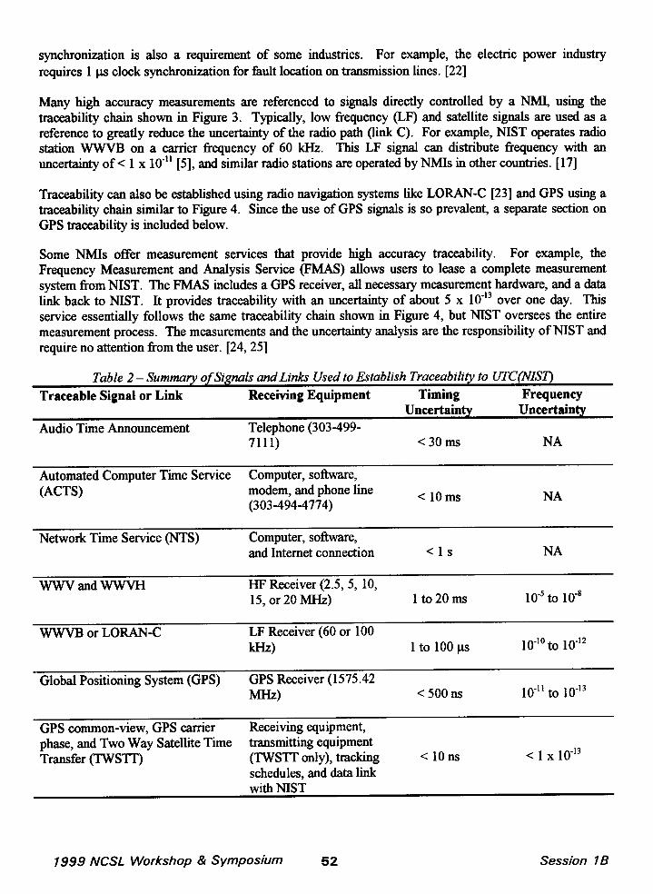
Table 2 – Summary of Signs 1sand Links Used to Establish Traceability to UTC(NISI)
Traceable Signal or Link Receiving Equipment Timing FrequencyUncertainty Uncertainty
Audio Time Announcement Telephone (303-499-711i) <30ms NA
Automated Computer Time Service Computer, software,(ACTS) modem, and phone line
(303-494-4774)<lo Ins NA
Network Time Service (NTS) Computer, software,and Internet connection <1s NA
WWVand WWVH HP Receiver (2.5,5, 10,15, or 20 MHz) lto20ms 10-5to 10-8
WWVB or LORAN-C LF Receiver (60 or 100kHz) 1 to 100 p
1o-1oto ~o-12
Global Positioning System (GPS) GPS Receiver (1575.42MHz) <500 ns ~o.ll to ~o-13
GPS common-view, GPS carrier Receiving equipment,phase, and Two Way Satellite Time transmitting equipmentTransfer (TWSTT) (TWSTT only), tracking <lolls <1 x 10”13
schedules, and data linkwith NIST
1999 NCSL Workshop & Symposium 52 Session lB

The most sophisticated methods of measuring time and frequency are normally reserved for comparisonsmade between NMIs, to control broadcast services, or for advanced military or space applications.However, they can be applied to other users who need traceability with the smallest possible uncertainty.These methods include single channel GPS common view [26], multi channel GPS common view [27],multi channel GPS+GLONASS common view [28], two-way satellite time transfer [29], and GPS carrierphase measurements. [30] These methods require a data exchange with a NMI, so the measurementresults are not known in real time. However, they make it possible to directly link to a NMI withuncertainties of < 1 x 10-13. The single channel GPS common view method is the most establishedtechnique. It uses standardized tracking schedules and a data format published by the BIPM, and astouched on earlier, is the method used by NMIs to contribute data for the computation of TAI and UTC.NIST also offers a Global Time Service that allows direct comparisons to UTC(IWST) through GPScommon view measurements. [25]
Table 2 summan“zesthe signals and links that can be used to establish traceability to UTC(NIST) for bothlow and high accuracy measurements.
5. Traceability Using the Global Positioning System (GPS)Inthe past decade, signals broadcast from GPS satellites have become the dominant reference source forhigh accuracy time and fkequency measurements. GPS consists of an orbiting constellation of at least 24satellites and at least four should be visible at all times from any location on Earth. Although some GPSsignals are reserved for United States militq use, the L 1 carrier (1575.42 MHz) is available to all users.
GPS is a navigation and positioning service that produces time and frequency information as a byproduct.The time and frequency component of GPS is officially referenced to UTC(USNO), the time scalemaintained by the United States Naval Observatory. However, there are at least two ways to establishtraceability to a NMI (rather than to USNO) using GPS.
The first way uses the model shown earlier in Figure 4. It requires a NMI to continually measure signalsfi-omthe GPS constellation, and compare GPS to their derivation of UTC. The resulting data must thenbe published and made available to users. As before, link A connects the BIPM to the NMI, and thisuncertainty can be obtained from Circular T. Link B connects the NMI to GPS. This link is establishedthrough the NMI’s measurements of the GPS signals, and the uncertainties are published and madeavailable to users. Link C connects the NMI to the user. As before, link D is the uncertainty introducedby the user’s measurement equipment. By comparing link B to their actual measurement results, userscan determine if they are properly receiving and processing the GPS signals.
The second way is to use a calibration service provided by a NMI that uses GPS signals, such as the NISTFrequency Measurement and Analysis Service. This service follows the traceability model shown inFigure 4, but all aspects of the measurement process (including the measurement hardware and theuncertainty analysis) are supplied or controlled by NIST. [24, 25]
One limitation of GPS monitoring is that a single NMI cannot monitor all the satellites all the time.Unlike fixed position transmitters, signals from the orbiting GPS satellites can only be received as theyfly over a NMI. Since the satellites have an orbital period of slightly less than 12 hours, they fly overtwice in a 24 hour period. Several hours of data can be collected in each fly over.
1999 AfCSL Workshop & Symposium 53 Session 7B

Several NMIs now monitor GPS and publish &ta on the Internet. Some publish data from individualsatellites, others publish a composite average of the entire constellation. NIST monitoring captures about400 minutes of data from each satellite per day (Figure 5) and is available at:
http://gpsmonitor.timefieq.bMrdoc.gov/gpstrace.htm
Completing the traceability chain shown in Figure 4 requires analyzing the measurement uncertain~ oflinks C and D, The uncertainty of link C is limited by the Selective Availability (SA) program initiatedby the United States Department of Defense, which intentionally degrades the accuracy of GPS. Due toSA, the GPS specification lists the timing uncertainty as 340 ns. [31]
The uncertainty of link D is receiver dependent. Some receivers reduce the effects of S& but others mayperform worse than the GPS signal specification. While performance differences also exist with othertypes of time and frequency receivers, the differences between GPS receivers are more pronounced due tothe increased complexity of the signal processing. A study conducted by the National PhysicalLaboratcxy (NPL) in the United Kingdom showed that the uncertainty of a GPS measurement varieswidely depending upon the model of receiver used. [32]
GPS Monitoring Data for 1999-0248(as received at NIST in Boulder, Colorado)
: UTC(NIST)- i UTCINIST)-Minutes~ GPSPRN ~ GPSPRNIn View ~Mean Value\ peak40-peak
(ns) ~ (ns]
7
248 [MJl) 51217)
m
+0.09 \ <1.0x 10¹³ ] 3.8x10¹³
Figure 5 – The NIST GPS Data Archive
A GPS receiver that is tx-o~erlv desijzned and operated can establish traceability to a NMI with anuncertainty of < 1 x 10-12when ave&ed for on; day. However, users should ‘&reiidly analyze theuncertainty of link D before claiming this level of performance. Two key factors that contribute to GPSreceiver performance are the quality of the receiver’s internal oscillator and the quality of the firmwarealgorithms that control the receiver. Receivers with oven controlled quartz or rubidium oscillatorsprovide the best stability since the receiver can ignore most of the fluctuations caused by SA. Highquality firmware can produce results that are better than the GPS specification by selecting the satellites
1999 NCSL Workshop & Symposium 54 Session lB

that provide the best time and frequency reference, by filtering the effects of S~ by averaging data frommultiple satellites to reduce the effeet of S~ and by properly handling GPS broadcast errors.
6. SummaryEstablishing traceability is often more convenient in time and frequency than in other fields of metrology.Direct links to a national metrology institute are often available in the form of signals broadeast over aradio, telephone, or network path. Trace.ability can also be established by receiving signals monitored bya NMI. Since traceability is required for both low and high accuracy applications, techniques exist toestablish traceability at uncertainties ranging from parts in 103to 10’3.
References
[1]
[2]
[3]
[4]
[5]
[6]
[7]
[8]
[9]
[10]
[11]
[12]
[13]
[14]
International Vocabula~ of Basic and General Terms in Metrology, second edition, InternationalOrganizationfor Standardization(ISO), 1993.
ISOiIEC Guide 25, General Requirements for the Competence of Calibration and Testing Laboratories,InternationalOrgmization for Standmdkmtion(1S0), 1990.
T. J. @@ “The BIPM and the AccurateMeasurementof Time,”Proc. IEEE,Vol. 79, No. 7, July 1991,pp. 894-905.
C. Thomas and J. Azoubib, “Upper Limits of Weights in TAI Computation” Proc. 2P AnnualPreciseTime and Time Interval Meeting, 1995, pp. 193-205.
R. Beehler and M. A. Lombardi, “MST Time and FrequencySetices,” Natl. Inst. Stand Technol. S’c.Publ. 432, 1991.
C. D. Ehrlich and S. D. Rasberry, “MetrologicalTimelines in Tmceabilky: Metrologia, vol. 34, no. 6,1997,pp. 503-514.
A. R. Robertson,P. L. M. Heyde_ I. A. Castelazo,“InternationalRepofi North AmericanMetrologyCooperation(NORAMET),”Metrologia, vol. 34, no. 2, 1997, pp. 195-196.
H. P. Layer, RD. Deslattes,and W. G. Schweitzer,Jr., “Laserwavelengthcomparisonby high resolutioninterferometry,”Applied Optics, vol. 15,no. 3, March 1976,pp. 734-743.
D. Re_ T. J. WiU D. Andreone,R Cerri, and A. Godone, “Comparisonof the Josephson voltagestandardsof the IEN and the BIPM,”Metrologia, vol. 35, 1998,pp. 21-24.
B. W. Petley, “Time and Frequencyin FundamentalMetrology: Proc. IEEE, Vol. 79, No. 7, July 1991,Pp. 1070-1076.
T. G. Butcher, T. L. Grimes, and J. S. Williams, “Specifications, Tolerances, and other TechnicalRequirementsfor Weighingand MeasuringDeviees,”Natl. Inst. Stand. Technol. Handb. 44, 1998.
R. J. Anderson and G. L. Harrisj “Specificationsand Tolerancesfor Field Standard Stopwatches: NatlInst. Stand. Technol. Hana%. 105-5, October 1997.
U. S. Dept of Transportation NationalHighwayTrafficSafetyAdministration “PoliceTrafficRadar IssuePaper: Dept. of Transportation HS-805 254, Februmy1980.
Young, W. L., “Legal Ckdibration(Certification)of Police Traffic Control Devices (RAD~ LASERVASCAR),”Proc. Natl. Con$ Stand. Lab., 1998, pp. 199-201.
1999 NCSL Workshop & Symposium 55 Session IB

Federal CommunicationsCommissionRule 73.1545.[15]
[16]
[17]
[18]
[19]
[20]
[21]
[22]
[23]
[24]
[25]
[26]
[27]
[28]
[29]
[30]
[31]
[32]
G. Kamas and M. A. Lombar~ “Time and Frequency Users Manual,” iVatl. Inst. Stand Technol.Spec.Publ. 559, 1990.
International TelecommunicationUnioU “Time Signals and Frequency Nan&r& Emissions; ITU-RRecommendations, TF Series, 1998.
J. Levine,M. Weiss,D. D. Davis,D. W. AlltuLand D. B. SullivW “TheNET AutomatedComputerTimeService: Nat/. Inst. Stand.Technol.J Res., Vol. 94,No. 5, September-October1989,pp. 311-321.
J. Levine, “TheNJSTInternetTime Services,”Proc. 25&Annual Precise Time and Time Interval Meeting,1993, pp. 505-511.
National Associationof SecuritiesDealers(NASD)Rule 6357.
Hewlett-Packard Company, “synchronizing Telecommunications Networks: synchronizingSDWSONET,”Hewlett-PackurdApplication Note 1264-2,1995.
R E. Wilson, “Uses of Precise Time and Frequencyin Power Systems,”Proc. L??EE,Vol. 79, No. 7, July1991, pp. 1009-1018.
NET continuouslycomparesthree LORAN-Cchains (8970,%10, and 9940)to UTC(NIST)and publishesthe results at http://gpsmonitor.timefkq.bldrdoc.gov/lorantrace.htm.
M. A. Lombardi, “NIST FrequencyMeasurementService,”Cal. Lab. Int. J. Metrology, May-June 1995,pp. 11-17.
J. L. MarshaU,cd., “NIST Calibration ServicesUsers Guide: Natl. Inst. Stand Technol.S’c.Publ. 250,1998,pp. 195-1%.
D. W. Allan and M. Weiss, “AccurateTime and Frequency Tmnsfer during Common-Viewof a GPSsatellite,”Proc. 34* Symp. on Freq. Control, IEEE, 1980, pp. 334-356.
R P. Gifbrdj L. S. Cutler, J. A. Kusters, M. ~ and D. W. Al@ “Continous MuIt-Channel,Common-View, L1-GPS Time Comparison over a 4,000 km Baseline: Proc. 50th Swnp. On Freq.Control,IEEE,1996.
W. Lewandowski and J. Azoubib, “GPS+GLONASS:Toward Subnanosecond Time Transfer; GPSWorld, Vol. 9, No. 11,November1998,pp. 30-39.
D. W. HansoIL“Fundamentalsof Two-WayTime Transfersby Satellitefl Proc. 43ti S’p. Freq. Control,IEEE, 1989, pp. 174-178.
K. M. Larsonand J. I.&vine,“TimeTransferUsing the Phase of the GPS Carrierj”Proc. 5P S’p. Freq.
Control, IEEE, 1998,pp. 292-297.
U. S. Department of Transportation “Federal Radionavigation Pm” DOT-?’IW%C-RSPA-97-2,DOD-4650.5, 1996, p. 137.
J. A. Davis and J. M. Furlongj “Report on the Study to Determine the Suitability of GPS DisciplinedOscillatorsas Time and FrequencyStandardsTraceableto the UK National Time ScaleUTC(NPL)”,Nat.Phys. Lab. (NPL) Report CIM 1, June 1997.
1999 NCSL Workshop & Symposium 56 Session IB