TR 182 031 - V3.1.1 - Telecommunications and Internet ... · GC Gate Control Gq' reference point...
31
ETSI TR 182 031 V3.1.1 (2010-09) Technical Report Telecommunications and Internet converged Services and Protocols for Advanced Networking (TISPAN); Remote CPN QoS Control; Study on CPN - RACS Interaction
Transcript of TR 182 031 - V3.1.1 - Telecommunications and Internet ... · GC Gate Control Gq' reference point...

ETSI TR 182 031 V3.1.1 (2010-09)
Technical Report
Telecommunications and Internet converged Services andProtocols for Advanced Networking (TISPAN);
Remote CPN QoS Control;Study on CPN - RACS Interaction
ETSI
ETSI TR 182 031 V3.1.1 (2010-09) 2
Reference DTR/TISPAN-02078-NGN-R3
Keywords architecture, QoS
ETSI
650 Route des Lucioles F-06921 Sophia Antipolis Cedex - FRANCE
Tel.: +33 4 92 94 42 00 Fax: +33 4 93 65 47 16
Siret N° 348 623 562 00017 - NAF 742 C
Association à but non lucratif enregistrée à la Sous-Préfecture de Grasse (06) N° 7803/88
Important notice
Individual copies of the present document can be downloaded from: http://www.etsi.org
The present document may be made available in more than one electronic version or in print. In any case of existing or perceived difference in contents between such versions, the reference version is the Portable Document Format (PDF).
In case of dispute, the reference shall be the printing on ETSI printers of the PDF version kept on a specific network drive within ETSI Secretariat.
Users of the present document should be aware that the document may be subject to revision or change of status. Information on the current status of this and other ETSI documents is available at
http://portal.etsi.org/tb/status/status.asp
If you find errors in the present document, please send your comment to one of the following services: http://portal.etsi.org/chaircor/ETSI_support.asp
Copyright Notification
No part may be reproduced except as authorized by written permission. The copyright and the foregoing restriction extend to reproduction in all media.
© European Telecommunications Standards Institute 2010.
All rights reserved.
DECTTM, PLUGTESTSTM, UMTSTM, TIPHONTM, the TIPHON logo and the ETSI logo are Trade Marks of ETSI registered for the benefit of its Members.
3GPPTM is a Trade Mark of ETSI registered for the benefit of its Members and of the 3GPP Organizational Partners. LTE™ is a Trade Mark of ETSI currently being registered
for the benefit of its Members and of the 3GPP Organizational Partners. GSM® and the GSM logo are Trade Marks registered and owned by the GSM Association.

ETSI
ETSI TR 182 031 V3.1.1 (2010-09) 3
Contents
Intellectual Property Rights ................................................................................................................................ 4
Foreword ............................................................................................................................................................. 4
1 Scope ........................................................................................................................................................ 5
2 References ................................................................................................................................................ 5
2.1 Normative references ......................................................................................................................................... 5
2.2 Informative references ........................................................................................................................................ 5
3 Abbreviations ........................................................................................................................................... 6
4 Use case analysis ...................................................................................................................................... 7
4.1 Reference scenarios and use cases ..................................................................................................................... 7
4.1.1 Reference scenarios ...................................................................................................................................... 8
4.1.1.1 Access configuration scenarios ............................................................................................................... 8
4.1.1.2 NGN connection scenarios ...................................................................................................................... 9
4.1.2 Use cases ..................................................................................................................................................... 10
4.1.2.1 Access Line Resource and Admission control ...................................................................................... 10
4.1.2.2 Access Line Policy Installation ............................................................................................................. 10
4.1.2.3 CPN Resource and Admission control .................................................................................................. 10
4.1.2.4 CPN Policy Installation ......................................................................................................................... 11
5 Functional Requirements for RACS-CPN Interaction ........................................................................... 11
5.1 Access Line Policy Installation ........................................................................................................................ 11
5.1.1 Procedures................................................................................................................................................... 11
5.1.2 Elementary Functions ................................................................................................................................. 12
5.1.3 Policy Installation ....................................................................................................................................... 12
5.1.4 Informational Elements ............................................................................................................................... 12
5.2 CPN and Access Line Resource and Admission Control ................................................................................. 14
5.2.1 Procedures................................................................................................................................................... 14
5.2.2 Elementary Functions ................................................................................................................................. 15
5.2.3 Admission Control ...................................................................................................................................... 17
5.2.4 Policy Installation ....................................................................................................................................... 17
5.2.5 NA(P)T Traversal Assistance ..................................................................................................................... 17
5.2.6 Informational Elements ............................................................................................................................... 17
6 Use case mapping to the TISPAN NGN architecture ............................................................................ 19
6.1 Access Line Policy Installation ........................................................................................................................ 20
6.2 CPN and Access Line Resource and Admission Control ................................................................................. 22
7 Interworking with intra-CPN QoS control mechanisms ........................................................................ 23
8 Security and user privacy ....................................................................................................................... 24
9 Signalling functions and protocols ......................................................................................................... 24
9.1 Direct connection ............................................................................................................................................. 24
9.2 Indirect connection ........................................................................................................................................... 25
10 Evaluation and recommendations for future work ................................................................................. 25
Annex A: Comparable work in other standardization bodies ........................................................... 26
A.1 ITU-T ..................................................................................................................................................... 26
Annex B: Implementation examples .................................................................................................... 27
B.1 H(e)NB Implementation Scenario .......................................................................................................... 27
B.2 Untrusted non-3GPP access to 3GPP core network implementation Scenarios .................................... 28
History .............................................................................................................................................................. 31

ETSI
ETSI TR 182 031 V3.1.1 (2010-09) 4
Intellectual Property Rights IPRs essential or potentially essential to the present document may have been declared to ETSI. The information pertaining to these essential IPRs, if any, is publicly available for ETSI members and non-members, and can be found in ETSI SR 000 314: "Intellectual Property Rights (IPRs); Essential, or potentially Essential, IPRs notified to ETSI in respect of ETSI standards", which is available from the ETSI Secretariat. Latest updates are available on the ETSI Web server (http://webapp.etsi.org/IPR/home.asp).
Pursuant to the ETSI IPR Policy, no investigation, including IPR searches, has been carried out by ETSI. No guarantee can be given as to the existence of other IPRs not referenced in ETSI SR 000 314 (or the updates on the ETSI Web server) which are, or may be, or may become, essential to the present document.
Foreword This Technical Report (TR) has been produced by ETSI Technical Committee Telecommunications and Internet converged Services and Protocols for Advanced Networking (TISPAN).

ETSI
ETSI TR 182 031 V3.1.1 (2010-09) 5
1 Scope The present document covers a use case analysis for the interaction of the TISPAN Resource and Admission Control Sub-System (RACS) with the Customer Premises Network (CPN), as well as an analysis of required functional entities, reference points and information flows. Furthermore, requirements for interworking with in-home QoS control mechanisms are studied. The study concludes with a recommendation on the way, or ways, how RACS and CPN should interact and interface, i.e. on one or several interworking architecture(s) proposal(s), taking into account security and privacy aspects.
2 References References are either specific (identified by date of publication and/or edition number or version number) or non-specific. For specific references, only the cited version applies. For non-specific references, the latest version of the reference document (including any amendments) applies.
Referenced documents which are not found to be publicly available in the expected location might be found at http://docbox.etsi.org/Reference.
NOTE: While any hyperlinks included in this clause were valid at the time of publication ETSI cannot guarantee their long term validity.
2.1 Normative references The following referenced documents are necessary for the application of the present document.
Not applicable.
2.2 Informative references The following referenced documents are not necessary for the application of the present document but they assist the user with regard to a particular subject area.
[i.1] ETSI ES 282 001: "Telecommunications and Internet converged Services and Protocols for Advanced Networking (TISPAN); NGN Functional Architecture".
[i.2] ETSI ES 282 003: "Telecommunications and Internet converged Services and Protocols for Advanced Networking (TISPAN); Resource and Admission Control Sub-System (RACS): Functional Architecture".
[i.3] ETSI ES 282 004: "Telecommunications and Internet converged Services and Protocols for Advanced Networking (TISPAN); NGN Functional Architecture; Network Attachment Sub-System (NASS)".
[i.4] ETSI TS 185 003: "Telecommunications and Internet converged Services and Protocols for Advanced Networking (TISPAN); Customer Network Gateway (CNG) Architecture and Reference Points".
[i.5] Broadband Forum TR-069 CPE WAN Management Protocol v1.1, Issue 1 Amendment 2, December 2007.
[i.6] ETSI TS 124 229: "Digital cellular telecommunications system (Phase 2+); Universal Mobile Telecommunications System (UMTS); LTE; IP multimedia call control protocol based on Session Initiation Protocol (SIP) and Session Description Protocol (SDP); Stage 3 (3GPP TS 24.229)".
[i.7] ETSI TS 133 203: "Digital cellular telecommunications system (Phase 2+); Universal Mobile Telecommunications System (UMTS); LTE; 3G security; Access security for IP-based services (3GPP TS 33.203)".

ETSI
ETSI TR 182 031 V3.1.1 (2010-09) 6
[i.8] ETSI TS 183 048: "Telecommunications and Internet converged Services and Protocols for Advanced Networking (TISPAN); Resource and Admission Control System (RACS); Protocol Signalling flows specification; RACS Stage 3".
[i.9] ETSI TS 122 220: "Universal Mobile Telecommunications System (UMTS); Service requirements for Home Node B (HNB) and Home eNode B (HeNB) (3GPP TS 22.220)".
[i.10] 3GPP TR 23.830: "3rd Generation Partnership Project; Technical Specification Group Services and System Aspects; Architecture aspects of Home NodeB and Home eNodeB".
[i.11] ETSI TS 125 467: "Universal Mobile Telecommunications System (UMTS); UTRAN architecture for 3G Home Node B (HNB); Stage 2 (3GPP TS 25.467)".
[i.12] ETSI TS 187 001: "Telecommunications and Internet converged Services and Protocols for Advanced Networking (TISPAN); NGN SECurity (SEC); Requirements".
[i.13] ETSI TS 181 005: "Telecommunications and Internet converged Services and Protocols for Advanced Networking (TISPAN); Service and Capability Requirements".
[i.14] ETSI TS 123 402: "Universal Mobile Telecommunications System (UMTS); LTE; Architecture enhancements for non-3GPP accesses (3GPP TS 23.402)".
3 Abbreviations For the purposes of the present document, the following abbreviations apply:
ACP Admission Control Process AF Application Function ALG Application Layer Gateway ALP Access Line Policy Installation ALR Access Line Resource and Admission control A-RACF Access-Resource and Admission Control Function ASP Application Service Provider AVP Attribute-Value Pair BGF Border Gateway Function CCI Charging Correlation Information CND Customer Network Device CNG Customer Network Gateway CNG-ACF CNG-Admission Control Function CNG-PCF CNG-Policy Control Function CPE Customer Premise Equipment CPI CPN Policy Installation CPN Customer Premises Network CRA CPN Resource and Admission control C-RACF Core-Resource and Admission Control Function CSCF Call Session Control Function DITP Derivation and Installation of Traffic Policies DSL Digital Subscriber Line DSL Digital Subscriber Line DSLAM Digital Subscriber Line Access Multiplexer e4 reference point e4 ePDG evolved Packet Data Gateway EUTRAN Evolved UMTS Terrestrial Radio Access Network FE Functional Entity FTTH Fibre To The Home GC Gate Control Gq' reference point Gq' HMRP Handling of Media Request Priority H-RAC Home Resource and Admission Control entity HSRP Handling of Service Request Priority Ia reference point Ia

ETSI
ETSI TR 182 031 V3.1.1 (2010-09) 7
IMS IP Multimedia Sub-System IP Internet Protocol IPMC IP Packet Marking Control MITP Modification and Installation of new Traffic Policies MLD Multicast Listener Discovery MSAN Multi Services Access Node NA(P)T Network Address and optional Port Translation NASS Network Attachment Sub-System NAT Network Address Translation NBR NAT Binding Report NE Network Element NGN Next Generation Network PCRF Policy and Charging Rule Function P-CSCF Proxy-CSCF PDN Packet Data Network PON Passive Optical Fibre QMTD QoS and Priority Mapping - Technology Dependent QMTI QoS and Priority Mapping - Technology Independent QoS Quality of Service RACS Resource and Admission Control Sub-System RCEF Resource Control Enforcement Function Rd' Reference point Rd' Re Reference point Re Rf Reference point Rf Ri' Reference point Ri' RLC Rate Limiting Control Rq Reference point Rq Rr reference point Rr RRP Reservation of Resources Process SDP Session Description Protocol SIP Session Initiation Protocol SPDF Service-based Policy Decision Function TCP Transmission Control Protocol TDDP Technology Dependent Decision Point TISPAN Telecommunications and Internet converged Services and Protocols for Advanced Networking UDP User Datagram Protocol UE User Equipment VDSL Very high bit-rate Digital Subscriber Line VGCF Voice Gateway Control Functions x-RACF Generic Resource and Admission Control Function
4 Use case analysis This clause details reference scenarios where the described CPN-RACS interaction is applicable and use cases from the viewpoint of the RACS. The reference scenarios are studied regarding access network configuration options and ways to connect end devices in the CPN to the NGN. The derived use cases from the view of the RACS can be split into resource and admission control and policy installation processes, applicable on access lines and inside CPNs.
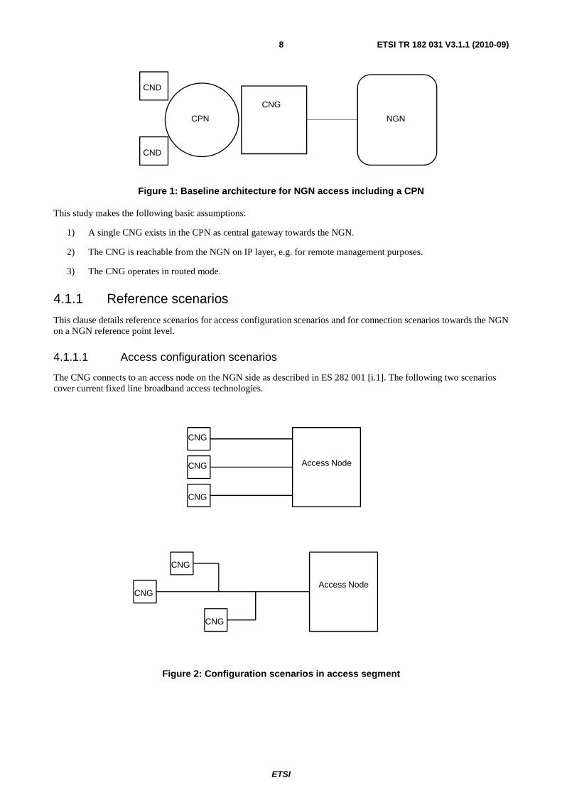
4.1 Reference scenarios and use cases In the TISPAN NGN functional architecture described in ES 282 001 [i.1], a User Equipment (UE) attaches directly to the NGN. TS 185 003 [i.4] defines an enhanced architecture where a Customer Network Gateway (CNG) can act either as a UE in case it has e.g. an embedded SIP client or where Customer Network Devices (CNDs) with embedded clients connect through a CNG to the NGN. In the latter case, depending on the use of signalling proxies in the CNG and whether the CNG works in routed or bridged mode, the reference points to the NGN are either local ones inside the Customer Premises Network (CPN) as defined in TS 185 003 [i.4] or the same ones as described in ES 282 001 [i.1]. Figure 1 depicts this architecture.
ETSI
ETSI TR 182 031 V3.1.1 (2010-09) 8
CND
CND
CNG
CPN NGN
Figure 1: Baseline architecture for NGN access including a CPN
This study makes the following basic assumptions:
1) A single CNG exists in the CPN as central gateway towards the NGN.
2) The CNG is reachable from the NGN on IP layer, e.g. for remote management purposes.
3) The CNG operates in routed mode.
4.1.1 Reference scenarios
This clause details reference scenarios for access configuration scenarios and for connection scenarios towards the NGN on a NGN reference point level.
4.1.1.1 Access configuration scenarios
The CNG connects to an access node on the NGN side as described in ES 282 001 [i.1]. The following two scenarios cover current fixed line broadband access technologies.
CNG
CNG
CNG
CNG
CNG
CNG
Access Node
Access Node
Figure 2: Configuration scenarios in access segment

ETSI
ETSI TR 182 031 V3.1.1 (2010-09) 9
The different options as shown in figure 2 are:
1) Each CNG has a dedicated, non-shared access line on its own. This is the case for e.g. xDSL access or FTTH access with dedicated fibres.
2) A number of CNGs from different customers share a common access line segment. This scenario covers e.g. shared PON access.
NOTE: In case PON is used to feed access nodes, option 1) applies. Each CNG has its dedicated access line.
4.1.1.2 NGN connection scenarios
For signalling and multimedia flows, three relevant options to connect to the NGN are possible according to TS 185 003 [i.4]. The three reference scenarios are shown in figure 3 with the corresponding reference points for signalling in the case of SIP signalling.
CND1
CNGCPNNGN
VGCF
CND2 GmGm
Proxy/ B2BUAGmGm‘
CND IMS
SIP UA
CND SIP UA
CND3
Z
IMS
RACS
NASS
Figure 3: Connection scenarios for CNDs (reference points for signalling shown)
The different options are:
1) The CNG itself is endpoint of signalling and media traffic. Reference points used are Gm for signalling with the IMS and Dj for all traffic including media. An example use case is when an analogue phone connects to the CNG. The CNG's VGCF acts as signalling and media endpoint on behalf of the CND (see CND3 in figure 3). Similar functions for other types of media would be possible but are not yet standardized in ETSI TISPAN.
2) The CNG is transparent to signalling and media traffic on a CND except for NA(P)T. Reference points in the case of SIP signalling are then the same as above: Gm and Dj (see CND2 in figure 3, only signalling reference points shown).
3) The CNG contains a signalling and/or media proxy as e.g. the Proxy B2BUA for the SIP signalling case and the CNDs traffic traverses this entity. Used reference points are then Gm' and Dj'. (See CND1 in figure 3, only signalling reference points shown.)
NOTE 1: Signalling over the Gm reference point may be encrypted, e.g. where IMS AKA as specified in TS 133 203 [i.7] and TS 124 229 [i.6] is used.
NOTE 2: The Home(e)NodeB example is described in annex B.

ETSI
ETSI TR 182 031 V3.1.1 (2010-09) 10
4.1.2 Use cases
This clause details the investigated use cases from the viewpoint of the RACS.
The deployment of guaranteed QoS requires mainly two steps in the control plane. An Admission Control Process (ACP) and a process for Modification and Installation of new Traffic Policies (MITP) as defined in ES 282 003 [i.2]. Dynamic admission control is vital to allow for resource sharing in access and customer premises networks without having to assign resources statically to specific devices or applications. The latter would disallow re-using such resources by other devices or applications in case the assigned device or application is idle. Policy control allows the installation and modification of rules on devices or applications e.g. to mark packets according to classification rules on egress interfaces or to police traffic on ingress interfaces. It also enables to dynamically allow or disallow specific traffic flows (Gate Control, GC). Whether there is a need for dynamic policy control depends thus on deployment scenarios and on the level of trust between network elements or applications.
NOTE: This study covers use cases for the traffic types defined in ETSI TISPAN, i.e. uni- or bidirectional unicast, and multicast originated from the NGN.
The use cases can be split into independent use cases that are valid for the access line and use cases that are valid for the CPN. Still, both can be combined.
4.1.2.1 Access Line Resource and Admission control
Admission control on the access line can be performed in current TISPAN definitions by two methods.
1) An A-RACF performs admission control as described in ES 282 003 [i.2]. This requires RACS to be aware of all sessions that require QoS. This also requires the RACS to be able to control the access node.
2) The CNG-ACF performs admission control as described in TS 185 003 [i.4]. This requires that either signalling originates in the VGCF or that signalling traffic is readable for the CNG's application layer gateway functions implemented in the Proxy B2BUA. The Proxy B2BUA has to then support all signalling protocols used. This method will not be sufficient in case of a shared access medium.
In a use case where the RACS is not aware of the resources on the access node (e.g. it controls the MSAN but not the DSLAMs in the case of GPON-fed VDSL), the admission control process can only be performed by the CNG.
Since the CNG can only be aware of the sessions that originate in itself or are unencrypted and detected by local ALGs, the RACS can solve this problem by interconnecting directly or indirectly to the CNG-ACF (Admission Control Function, see TS 185 003 [i.4]) and asking for resource reservation. Thus the following use case is determined:
• UC-ALR-1: The RACS interconnects with the CNG to request resource reservations on the access line.
4.1.2.2 Access Line Policy Installation
Dynamic policy installation and modification on the CNG is required to allow the CNG to dynamically prioritize, allow or block outgoing traffic towards the access line.
Policy installation can be provided by the CNG-PCF (Policy Control Function, see TS 185 003 [i.4]). Since this function requires an ALG in the CNG and cannot detect encrypted signalling, this approach is limited.
As an alternative, static (i.e. non-session-based) policies can be provisioned on the CNG e.g. by using the TR-69 Management Framework from the Broadband Forum [i.5]. Using static policies comes with the drawback that it is not as granular as required for the media flows that are negotiated in real-time.
For dynamic policy installation on the CPN's side of the access line, the following use case results from this analysis:
• UC-ALP-1: The RACS interconnects with the CNG to request policy installation in the CNG's uplink interface towards the NGN.
4.1.2.3 CPN Resource and Admission control
In case a CND connects to the CNG through a CPN, the traffic from the CND competes with traffic from other CNDs as shown in figure 3 where CNDs 1 and 2 may compete for resources inside the CPN.

ETSI
ETSI TR 182 031 V3.1.1 (2010-09) 11
Thus, an admission control process inside the CPN is required. Using ALGs comes again with the above described shortcomings. Two possible approaches can be thought of in the scope of RACS-CPN interaction:
• UC-CRA-1: The RACS requests resources from the CNG and the CNG itself reserves resources inside the CPN as a completely separate process.
• UC-CRA-2: The RACS interconnects to all network elements inside the CPN for the purpose of resource and admission control.
UC-CRA-2 is not further considered within the scope of the present document due to privacy and security reasons. Furthermore - although in principle technically feasible - scalability problems are expected due to the growing amount of in-home devices.
4.1.2.4 CPN Policy Installation
Dynamic policy installation inside the CPN may be required. Two possible approaches can be thought of in the scope of RACS-CPN interaction:
• UC-CPI-1: A new FE in the CNG requests for policy installation inside the CPN based on a previous resource and admission control procedure triggered by the RACS.
• UC-CPI-2: The RACS interconnects to all network elements inside the CPN for the purpose of policy installation.
UC-CPI-2 is not further considered within the scope of the present document due to privacy and security reasons. Furthermore - although in principle technically feasible - scalability problems are expected due to the growing amount of in-home devices.
5 Functional Requirements for RACS-CPN Interaction This clause describes the functional requirements for the interaction of RACS with the CPN for the use cases UC-ALP-1, UC-CRA-1 and UC-ALR-1. For all use cases, the RACS needs to interconnect to a functional entity inside the CPN which is named in this clause H-RAC and further de-composed in the next clauses of this study. Since the CNG is the central gateway towards the NGN and the only device where reachability from the NGN side is given, the H-RAC is embedded in the CNG. Clause 6 further specifies this function.
CNG
NGN
RACS
Access line
H-RAC
CPN
Figure 4: RACS interconnection to the CNG (generic view)
5.1 Access Line Policy Installation For use case UC-ALP-1, RACS performs resource and admission control on the access line and requests policy installation from the CNG for traffic prioritization on its interface towards the NGN.
5.1.1 Procedures
The RACS requests policy installation for a set of flows by sending a policy installation request towards the H-RAC. The H-RAC replies to this request as depicted in figure 5.

ETSI
ETSI TR 182 031 V3.1.1 (2010-09) 12
RACSH-RAC
(1) Locate CNG
(3) Enforcement
Control
(2) Policy Installation Request
(4) Policy Installation Reply
Figure 5: RACS interconnection to the CNG (generic view)
The required steps are as follows:
1) The RACS determines based on local policies whether a CNG is to be queried and then locates the CNG.
2) The RACS requests local policy installation.
3) The H-RAC enforces the appropriate policies on the access line.
4) The H-RAC confirms the resource availability to the RACS.
5.1.2 Elementary Functions
The required elementary function for the RACS beyond those defined in [i.2] are:
1) Determine based on local policies if the CNG needs to be contacted.
2) Locate the CNG and its H-RAC functional entity.
In this scenario, for each multimedia session the H-RAC needs to implement the installation, modification and removal of policies, similar to an RCEF as described in [i.2], clause 6.3.7.1.1.1. The required elementary functions are:
1) Installation of Policies.
2) Gating.
3) Packet Marking.
4) Traffic Policing.
5) Removal of Policies.
6) Revoke of policies indication.
This enables the CNG to support the prioritization of media flows in both directions with appropriate QoS on the access line interface. Details of the elementary functions are to be found in [i.2].
5.1.3 Policy Installation
Upon receiving the request for policy installation, the H-RAC installs the appropriate policies on the CNG.
5.1.4 Informational Elements
The required informational elements for the H-RAC in the access line policy installation case are a subset of those of the Re reference point between x-RACF and RCEF as defined in clause 6.3.7 of ES 282 003 [i.2]. While the Function of the x-RACF is restricted to an A-RACF, the function of the H-RAC in the use case here is the one of an RCEF. Table 1 lists the required informational elements.

ETSI
ETSI TR 182 031 V3.1.1 (2010-09) 13
Table 1: Policy Enforcement Install Request - Information Elements
Policy Enforcement Install Request (A-RACF -> H-RAC) Request Originating Function Identifier Globally unique Identifier for the Request Originating
Function instance. Resource Reservation Session ID The reference is a unique resource reservation session
identifier in the scope of the Request Originating Function Identifier.
Policy Rule Installation (see note 1) The Policy Rule description, which is used to activate and install a new Policy Rule as instructed from the A-RACF to the H-RAC.
Policy Rule Definition (see note 2) The Policy Rule definition. Policy Rule ID The identifier of a new Policy Rule to be activated at the
H-RAC. Direction (see note 3) Direction of the flow. Flow Id Identifier for the specific flow. Flow control (see note 3) Enables or disables the opening of a gate to a particular flow. IP Addresses (see note 3) Source and Destination IP addresses and Address Realm
that each address belongs to (see note 4). Ports (see note 3) Source and Destination Port Numbers (see note 5). Protocol (see note 3) Protocol Id. Bandwidth (optional, see note 3) The maximum request bit rate. Reservation Class (optional, see note 3)
A particular index that identifies a set of traffic characteristics of the flow (e.g. burstiness and packet size).
Transport Service Class (optional, see note 3)
Identifies the forwarding behaviour to be applied to the particular flow (see note 6).
Precedence Indicates the precedence that a Policy Rule should take when related to others.
Report Type Indicates the type of reporting that the H-RAC is supposed to provide to the A-RACF.
Policy Rule ID The identifier of a pre-defined Policy Rule to be activated at the H-RAC.
Policy Rule Group ID (optional) The identifier of a set of pre-defined Policy Rules to be activated at the H-RAC.
Traffic Class ID (optional) The identifier of a traffic class to be associated with a policy rule.
NOTE 1: There needs to be at least one Information Element of this type present in the message. NOTE 2: If Policy Rules for each direction need to be specified, several Policy Rule definitions have to be
included. NOTE 3: These Information Elements describe the flow. Zero, one or several of them may be included in
the Policy Rule definition, in order to associate a given Policy Rule with IP Flows. NOTE 4: An IP address prefix is supported. NOTE 5: Port ranges are supported and can be defined by specifying the minimum and maximum value
or by using a wildcard. NOTE 6: Transport Service Class is also part of the QoS profile provided by NASS (see ES 282 004
[i.3]).
The informational elements from the x-RACF - RCEF interconnection, which allow an RCEF to identify a (virtual) subscriber port that the IP flow(s) traverse, are not required for access line policy installation on the CPN side. Thus, the elements Subscriber-ID, Physical Access ID and Logical Access ID are not required.
NOTE: In the case of NA(P)T in the CNG, the standard procedure in TISPAN RACS is to include the CPN-local address and the globally reachable address of the BGF in the flow description (see [i.8]). This allows the CNG to identify flows and is sufficient even in the situation prior to creation of a NA(P)T binding . The CNG can create a NA(P)T binding upon installation of the policy, before having received a first packet matching the flow description from the CND.

ETSI
ETSI TR 182 031 V3.1.1 (2010-09) 14
The policy installation response contains the following informational elements:
Table 2: Policy Enforcement Installation/Modification Confirmation - Information Elements
Policy Enforcement Installation/Modification Confirmation (H-RAC -> A-RACF) Request Originating Function Identifier Global unique Identifier for the Request Originating Function
instance. Resource Reservation Session ID The reference is a unique resource reservation session
identifier in the scope of the Request Originating Function Identifier.
Result (conditional, see notes 1 and 2) The result according to the type of the request. NOTE 1: This Information Element is not generated by the H-RAC in response to a policy removal
request performed in Policy Enforcement Modification Request message. NOTE 2: This Information Element is always generated and returned in the remaining cases, i.e. in
response to Policy Enforcement Installation Request messages, or in response to Policy Enforcement Modification Request messages sent by the A-RACF to activate a pre-defined, but not yet activated, Policy Rule; or to install and activate a new Policy Rule; or to modify Policy Rule(s) previously installed and activated; or to deactivate Policy Rule(s).
5.2 CPN and Access Line Resource and Admission Control For use cases UC-ALR-1 and UC-CRA-1, RACS requests resources from the CNG and the CNG itself reserves resources inside the CPN and/or on the access line as a separate process. The resource and admission control steps trigger the policy installation steps from UC-ALP-1 and UC-CPI-1 implicitly either with the admission control process (single stage method) or upon a separate commit request (two-stage method).
5.2.1 Procedures
RACS requests resources from the CPN and/or access line by sending a request to and receiving a response from the H-RAC whether resources are available. In case resources are available they become reserved with the response. Depending on the used method, resources are immediately available with a successful response or the H-RAC requires a succeeding commit request by the RACS to enforce the appropriate policies in CPN and on the access line. Those two options are referred to in [i.2] as "single stage resource management model" and "two-stage reserve-commit management model". The latter is depicted in figure 6.
RACSH-RAC
(1) Locate CNG
(3) Admission
Control
(6) Enforcement
Control
(2) Resource Request
(4) Resource Request Relpy
(5) Resource Commit Request
(7) Resource Commit Reply
Figure 6: Two stage high level CPN resource request/response flow
The required steps are as follows:
1) The RACS determines based on local policies whether a CNG is to be queried and then locates the CNG.
2) RACS requests resources from the CNG's H-RAC function.
3) The H-RAC performs the admission control process. Admission control is performed for access line resources and if needed for intra CPN resources (see clause 7).

ETSI
ETSI TR 182 031 V3.1.1 (2010-09) 15
4) The CNG replies to the RACS that resources have been reserved.
5) The RACS sends a commit request to the H-RAC.
6) The H-RAC enforces the appropriate policies on the access line interface and inside the CPN if needed.
7) The H-RAC confirms the resource availability to the RACS.
In case of using the single-stage method, steps 4) and 5) are not executed.
5.2.2 Elementary Functions
The required elementary function for the RACS beyond those defined in [i.2] are:
1) Determine based on local policies if the CNG needs to be contacted.
2) Locate the CNG and its H-RAC functional entity.
The required elementary functions for the H-RAC are similar to those of an A-RACF as defined in clause 6.2.2 of [i.2]. Table 3 lists the common elementary functions.

ETSI
ETSI TR 182 031 V3.1.1 (2010-09) 16
Table 3: Required and optional functions in H-RAC common to x-RACF definitions in [i.2]
Acronym x-RACF Elementary Function
(see [i.2])
Description from x-RACF (see [i.2])
H-RAC specifics H-RAC
AAoRFE R3 and beyond
Authentication and authorization of the Requesting FE
Authentication and authorization of the FE requesting resources. M
CGRC R3 and
beyond
Check global resource capabilities
Check if the total of the requests match the global resource capabilities.
Includes access line and/or CPN depending on use case
M
ACP Admission control process Derivation of a QoS profile and check of the availability of resources for unicast and multicast services.
M (see note)
RRP Reservation of resources process
Resource reservation taking into account the resource management scheme used in the SPDF request, i.e. single-stage resource management, two-stage reserve-commit resource management, or authorize-reserve-commit resource management.
M (see note)
DITP Derivation and Installation of Traffic Policies
Derive and install of QoS parameters as part of L3/L2 traffic policies.
M (see note)
QMTD QoS and Priority Mapping - Technology Dependent
Mapping of the network QoS parameters to transport (technology-dependent) QoS parameters.
M
TDDP Technology Dependent Decision Point
Makes technology-dependent and resource-based admission decisions for unicast and multicast services.
M
MITP Modification and Installation of new Traffic Policies
Actions taken upon QoS handling process, e.g. by monitoring and controlling of access resources.
O
HMRP Handling of media request priority
Ability to handle the media priority received in the resource reservation request.
M
QMTI QoS and Priority Mapping - Technology Independent
Maps the service QoS requirements and priority received from the AF to network QoS parameters (e.g. Y.1541 class) and priority.
M
GC Gate Control Controls the opening and closing of a gate. M
IPMC IP Packet Marking Control Decides on the packet marking and remarking of traffic flows. M
RLC Rate Limiting Control Decides on the bandwidth limit of traffic flows (e.g. for policing). M
HSRP Handling of service request priority
Ability to indicate a service priority level in the resource reservation request.
M
PPS Policy based path selection Ability to choose the best appropriate path for the requested service flow according to network policy, the requestor class, the quality requirements and network resource status, and to indicate the selected path to the RCEF.
O
NOTE: In case the admission control decision is delegated to a subtended FE in the CPN, this is not mandatory for the delegating H-RAC FE.
To solve CPN-specific tasks, the following list of additional functions is to be provided by the H-RAC.
ETSI
ETSI TR 182 031 V3.1.1 (2010-09) 17
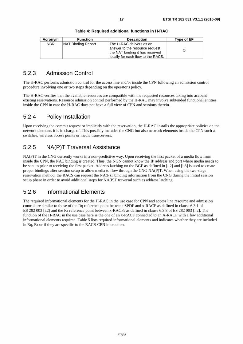
Table 4: Required additional functions in H-RAC
Acronym Function Description Type of EF NBR NAT Binding Report The H-RAC delivers as an
answer to the resource request the NAT binding it has reserved locally for each flow to the RACS.
O
5.2.3 Admission Control
The H-RAC performs admission control for the access line and/or inside the CPN following an admission control procedure involving one or two steps depending on the operator's policy.
The H-RAC verifies that the available resources are compatible with the requested resources taking into account existing reservations. Resource admission control performed by the H-RAC may involve subtended functional entities inside the CPN in case the H-RAC does not have a full view of CPN and sessions therein.
5.2.4 Policy Installation
Upon receiving the commit request or implicitly with the reservation, the H-RAC installs the appropriate policies on the network elements it is in charge of. This possibly includes the CNG but also network elements inside the CPN such as switches, wireless access points or media transceivers.
5.2.5 NA(P)T Traversal Assistance
NA(P)T in the CNG currently works in a non-predictive way. Upon receiving the first packet of a media flow from inside the CPN, the NAT binding is created. Thus, the NGN cannot know the IP address and port where media needs to be sent to prior to receiving the first packet. Address latching on the BGF as defined in [i.2] and [i.8] is used to create proper bindings after session setup to allow media to flow through the CNG NA(P)T. When using the two-stage reservation method, the RACS can request the NA(P)T binding information from the CNG during the initial session setup phase in order to avoid additional steps for NA(P)T traversal such as address latching.
5.2.6 Informational Elements
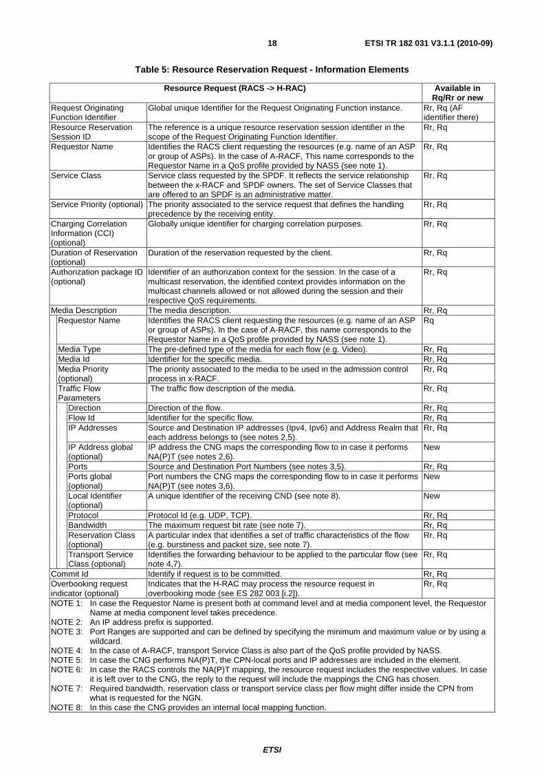
The required informational elements for the H-RAC in the use case for CPN and access line resource and admission control are similar to those of the Rq reference point between SPDF and x-RACF as defined in clause 6.3.1 of ES 282 003 [i.2] and the Rr reference point between x-RACFs as defined in clause 6.3.8 of ES 282 003 [i.2]. The function of the H-RAC in the use case here is the one of an x-RACF connected to an A-RACF with a few additional informational elements required. Table 5 lists required informational elements and indicates whether they are included in Rq, Rr or if they are specific to the RACS-CPN interaction.
ETSI
ETSI TR 182 031 V3.1.1 (2010-09) 18
Table 5: Resource Reservation Request - Information Elements
Resource Request (RACS -> H-RAC) Available in Rq/Rr or new
Request Originating Function Identifier
Global unique Identifier for the Request Originating Function instance. Rr, Rq (AF identifier there)
Resource Reservation Session ID
The reference is a unique resource reservation session identifier in the scope of the Request Originating Function Identifier.
Rr, Rq
Requestor Name
Identifies the RACS client requesting the resources (e.g. name of an ASP or group of ASPs). In the case of A-RACF, This name corresponds to the Requestor Name in a QoS profile provided by NASS (see note 1).
Rr, Rq
Service Class Service class requested by the SPDF. It reflects the service relationship between the x-RACF and SPDF owners. The set of Service Classes that are offered to an SPDF is an administrative matter.
Rr, Rq
Service Priority (optional) The priority associated to the service request that defines the handling precedence by the receiving entity.
Rr, Rq
Charging Correlation Information (CCI) (optional)
Globally unique identifier for charging correlation purposes. Rr, Rq
Duration of Reservation (optional)
Duration of the reservation requested by the client. Rr, Rq
Authorization package ID (optional)
Identifier of an authorization context for the session. In the case of a multicast reservation, the identified context provides information on the multicast channels allowed or not allowed during the session and their respective QoS requirements.
Rr, Rq
Media Description The media description. Rr, Rq Requestor Name Identifies the RACS client requesting the resources (e.g. name of an ASP
or group of ASPs). In the case of A-RACF, this name corresponds to the Requestor Name in a QoS profile provided by NASS (see note 1).
Rq
Media Type The pre-defined type of the media for each flow (e.g. Video). Rr, Rq Media Id Identifier for the specific media. Rr, Rq Media Priority (optional)
The priority associated to the media to be used in the admission control process in x-RACF.
Rr, Rq
Traffic Flow Parameters
The traffic flow description of the media. Rr, Rq
Direction Direction of the flow. Rr, Rq Flow Id Identifier for the specific flow. Rr, Rq IP Addresses Source and Destination IP addresses (Ipv4, Ipv6) and Address Realm that
each address belongs to (see notes 2,5). Rr, Rq
IP Address global (optional)
IP address the CNG maps the corresponding flow to in case it performs NA(P)T (see notes 2,6).
New
Ports Source and Destination Port Numbers (see notes 3,5). Rr, Rq Ports global (optional)
Port numbers the CNG maps the corresponding flow to in case it performs NA(P)T (see notes 3,6).
New
Local Identifier (optional)
A unique identifier of the receiving CND (see note 8). New
Protocol Protocol Id (e.g. UDP, TCP). Rr, Rq Bandwidth The maximum request bit rate (see note 7). Rr, Rq Reservation Class (optional)
A particular index that identifies a set of traffic characteristics of the flow (e.g. burstiness and packet size, see note 7).
Rr, Rq
Transport Service Class (optional)
Identifies the forwarding behaviour to be applied to the particular flow (see note 4,7).
Rr, Rq
Commit Id Identify if request is to be committed. Rr, Rq Overbooking request indicator (optional)
Indicates that the H-RAC may process the resource request in overbooking mode (see ES 282 003 [i.2]).
Rr, Rq
NOTE 1: In case the Requestor Name is present both at command level and at media component level, the Requestor Name at media component level takes precedence.
NOTE 2: An IP address prefix is supported. NOTE 3: Port Ranges are supported and can be defined by specifying the minimum and maximum value or by using a
wildcard. NOTE 4: In the case of A-RACF, transport Service Class is also part of the QoS profile provided by NASS. NOTE 5: In case the CNG performs NA(P)T, the CPN-local ports and IP addresses are included in the element. NOTE 6: In case the RACS controls the NA(P)T mapping, the resource request includes the respective values. In case
it is left over to the CNG, the reply to the request will include the mappings the CNG has chosen. NOTE 7: Required bandwidth, reservation class or transport service class per flow might differ inside the CPN from
what is requested for the NGN. NOTE 8: In this case the CNG provides an internal local mapping function.

ETSI
ETSI TR 182 031 V3.1.1 (2010-09) 19
The Rq/Rr informational elements Subscriber-ID and Globally Unique IP Address are not required for CPN interconnection since the subscriber is already identified when interconnecting with the CPN. The Rr informational elements Physical Access ID and Logical Access ID are not included for the same reason.
The new elements IP Address Global and Ports Global permit controlled NA(P)T traversal procedures where either the CNG's NA(P)T mapping table is controlled by the RACS or the CNG performs an independent decision and reports back the mapping to the RACS (see also clause 5.2.5).
A Local Identifier per flow is required e.g. in the case where resources for multicast are to be reserved. Current multicast procedures in TISPAN do not allow to determine the receiving CND prior to receiving an IGMP/MLD request to join a multicast group.
NOTE: Resource modification requests are similar to initial resource requests and thus not further detailed in the present document.
The informational elements for the reply to a resource reservation or modification request are listed in table 6. The table indicates for each element whether it is already included in the Rq or Rr specification or if it is specific to the RACS-CPN interaction.
Table 6: Resource Confirmation - Information Elements
Resource Req/Modification Confirmation (H-RAC -> RACS) (see notes) Available in Rq/Rr or new
Request Originating Function Identifier
Global unique Identifier for the Request Originating function instance. Rr, Rq (AF identifier there)
Resource Reservation Session ID
The reference is a unique resource reservation session identifier in the scope of the Request Originating Function Identifier.
Rr, Rq
Duration of Reservation Granted (optional)
Duration of the reservation granted by terminating H-RAC. Rr, Rq
Media Description (optional)
The media description. (See note 2.) New
Media Id Identifier for the specific media. (See note 2.) New Traffic Flow Parameters
The traffic flow description of the media. (See note 2.) New
Direction Direction of the flow. (See note 2.) New Flow Id Identifier for the specific flow. (See note 2.) New IP Address global (optional)
IP address the CNG maps the corresponding flow to in case it performs NA(P)T. (See notes 2, 3.)
New
Ports global (optional)
Port numbers the CNG maps the corresponding flow to in case it performs NA(P)T. (See notes 2, 4.)
New
Result The result of the request. Rr, Rq NOTE 1: The optional parameters are not present in case of an unsuccessful result. NOTE 2: The media description parameters are only used for controlled NA(P)T traversal. In case of controlled NA(P)T
travels, all parameters marked with this note are required. NOTE 3: An IP address prefix is supported. NOTE 4: Port Ranges are supported and can be defined by specifying the minimum and maximum value or by using a
wildcard.
Adding parts of the media description from the resource request allows for controlled NA(P)T traversal procedures where either the CNG's NA(P)T mapping table is controlled by the RACS or the CNG performs an independent decision and reports back the mapping to the RACS (see also clause 5.2.5). In the former case, the mappings reported back from the H-RAC can either confirm the requested mappings or overwrite them with a local decision.
6 Use case mapping to the TISPAN NGN architecture In this clause, the use cases described in the previous clauses are mapped to a the TISPAN RACS and CNG architectures. Two types of required functionalities for interconnection have been identified: One RCEF-like function using informational elements similar to the ones defined for the Re reference point and one x-RACF-like function using informational elements similar to those used on the Rq and Rr reference points.
Since the CNG architecture defined in TS 185 003 [i.4] already contains local functions similar to an x-RACF and an RCEF as shown in figure 7, RACS CPN interaction should take place between those functions and the RACS.

ETSI
ETSI TR 182 031 V3.1.1 (2010-09) 20
CNG-PCF
CNG-ACF
CNG-Proxy
/ B2BU
Gm‘ Gm
CPN CNG NGN
Dj
P-CSCF
Access
Node
CND
CND-SIP-UA
CND-CSMF
Figure 7: CNG-local resource and policy control
A CNG-ACF (Admission Control Function) is contacted by the local SIP Proxy/B2BUA and then performs an admission control procedure including local links such as the access line. Having granted admission, the CNG-ACF advises the CNG-PCF (Policy Control Function) to enable appropriate policies. These procedures are all CNG-internal. To allow for interaction with the RACS, the RACS needs to connect to those two functions.
6.1 Access Line Policy Installation Access line policy installation requires the RACS to interconnect with the CNG-PCF as depicted in figure 8.
Rr
x -RACF
AF
SPDF
BGFRCEF
NASS
Re Ia
Gq ’
Rd ’, Ri ’
Rq
e4
Transport Processing Functions
BTF Core Border NodeAccess Node
CNG
CNG-ACF
CNG-PCF
Rc
Rc’
CPN
Note: Rc and Rc‘ are only connecting to A-RACF instances
Figure 8: RACS CPN interaction, reference points
The x-RACF in figure 8 acts as an A-RACF in case it connects to the CPN. The CPN is directly connected with an Access Network where the functions of a C-RACF do not apply.
A new reference point is required which is named Rc'. As seen in the clause above, Rc' is very similar to the Re reference point.
As with the Re reference point, the Rc' reference point is of type intra-domain.
An example flow is depicted in figure 9.
ETSI
ETSI TR 182 031 V3.1.1 (2010-09) 21
CND AFCNG-ACF RACSCNG-PCF
(6) Perform resource request in network
And enforce policies
(1) SIP INVITE (Trigger)
(2) Req.
(4) Req.
(5) Conf.
(7) BGF control
(8) Conf
Additional signalingfor CPN interworking
(3) Locate CNGPerform admission control
(9) Session set-up continues
(10) Session set-up confirmation forwarded
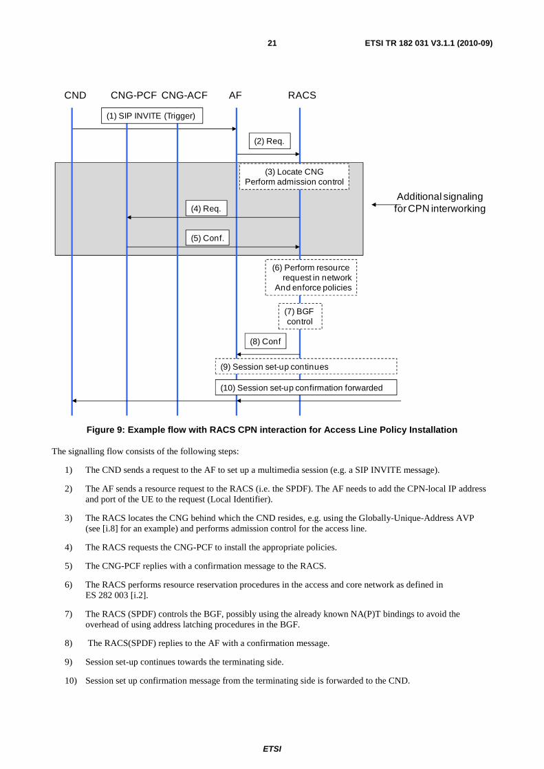
Figure 9: Example flow with RACS CPN interaction for Access Line Policy Installation
The signalling flow consists of the following steps:
1) The CND sends a request to the AF to set up a multimedia session (e.g. a SIP INVITE message).
2) The AF sends a resource request to the RACS (i.e. the SPDF). The AF needs to add the CPN-local IP address and port of the UE to the request (Local Identifier).
3) The RACS locates the CNG behind which the CND resides, e.g. using the Globally-Unique-Address AVP (see [i.8] for an example) and performs admission control for the access line.
4) The RACS requests the CNG-PCF to install the appropriate policies.
5) The CNG-PCF replies with a confirmation message to the RACS.
6) The RACS performs resource reservation procedures in the access and core network as defined in ES 282 003 [i.2].
7) The RACS (SPDF) controls the BGF, possibly using the already known NA(P)T bindings to avoid the overhead of using address latching procedures in the BGF.
8) The RACS(SPDF) replies to the AF with a confirmation message.
9) Session set-up continues towards the terminating side.
10) Session set up confirmation message from the terminating side is forwarded to the CND.

ETSI
ETSI TR 182 031 V3.1.1 (2010-09) 22
In the example, the CPN resources are reserved first. The policy installation steps 4) and 5) can also be performed after the admission control process in the NGN, depending on the likelihood that policies would have to be removed again in case admission control in the NGN fails.
6.2 CPN and Access Line Resource and Admission Control For the RACS to delegate CPN and/or access line resource and admission control procedures to the CNG, the RACS is required to interconnect to the local CNG-ACF as depicted in figure 8 with a new reference point named Rc. As seen in the clause above, Rc is very similar to the Rq and Rr reference points.
For intra-CPN resource and admission control, the CNG-ACF may need to perform procedures studied in clause 7.
As with the Rq and Rr reference points, the Rc reference point is of type intra-domain.
An example flow for the integration of the RACS-CPN interaction is depicted in figure 10.
CND AFCNG-ACF RACSCNG-PCF
(9) Perform resource request in network
And enforce policies
(1) SIP INVITE (Trigger)
(2) Req.
(4) Resource Req.
(8) Resources Conf.
(5) Check ResourcesIn Home network
(6) Req.
(7) Conf.
(10) BGF control
(11) Conf
Additional signalingfor CPN interworking
(3) Locate CNG
(12) Session set-up continues
(13) Session set-up confirmation forwarded
Figure 10: Example flow with RACS CPN interaction for CPN and Access Line Resource and Admission Control, single stage method
The signalling flow consists of the following steps:
1) The CND sends a request to the AF to set up a multimedia session (e.g. a SIP INVITE message).
2) The AF sends a resource request to the RACS (i.e. the SPDF). The AF needs to add the CPN-local IP address and port of the UE to the request (Local Identifier).

ETSI
ETSI TR 182 031 V3.1.1 (2010-09) 23
3) The RACS locates the CNG behind which the CND resides, e.g. using the Globally-Unique-Address AVP (see [i.8] for an example).
4) The RACS sends a resource request to the CNG-ACF. This request may include a proposed NA(P)T binding to use.
5) The CNG performs a local check of resources on the access line and inside the home network on the path to the UE that requested the service. For the latter it may interact with other network elements inside the home network (see clause 7). The CNG may also create the NA(P)T binding for the media at this early stage.
6) The CNG-ACF requests the CNG-PCF to install the appropriate policies.
NOTE 1: This is in current TISPAN specifications a CNG internal procedure [i.4].
7) The CNG-PCF replies with a confirmation message to the CNG-ACF.
NOTE 2: This is in current TISPAN specifications a CNG internal procedure [i.4].
8) The CNG-ACF replies to the RACS with a confirmation message. This reply may include the NA(P)T binding installed in the CNG for the media.
9) The RACS performs resource reservation procedures in the access and core network as defined in ES 282 003 [i.2].
10) The RACS (SPDF) controls the BGF, possibly using the already known NA(P)T bindings to avoid the overhead of using address latching procedures in the BGF.
11) The RACS (SPDF) replies to the AF with a confirmation message.
12) Session set-up continues towards the terminating side.
13) Session set up confirmation message from the terminating side is forwarded to the CND.
In the example, the CPN resources are reserved first. This comes with two advantages:
a) Resource bottlenecks are most likely to occur on the access line or inside the CPN. If there are insufficient resources in the CPN, then the access and core network resources need not be checked at all.
b) A NA(P)T binding can be obtained prior to any other RACS internal procedures, facilitating BGF control or even allowing the BGF to be bypassed, saving overhead.
The example depicts the single stage resource reservation method. The RACS CPN interaction can also use two stage procedures. The RACS can also internally perform two stages methods while the interaction with the CPN is using a single stage procedure.
7 Interworking with intra-CPN QoS control mechanisms In order to assure guaranteed QoS inside the CPN for the use cases UC-CRA-1 (CPN local admission control) and UC-CPI-1 (CPN local policy installation) actions need to be performed by the CNG. As shown in the above clause, when using the single stage method the CNG receives a resource request including an implicit request to install the appropriate policies immediately after granting resources. In the two stage method, the CNG receives the request to install the appropriate policies as a separate request from the RACS.
For intra-CPN resource and admission control, the CNG needs to implement additional functionality. A topology function within the CNG needs to be aware of the network topology and the CNDs attached to which Network Element (NE) in the CPN. A flow state module needs to track all flows which require guaranteed QoS inside the CPN. A management function needs to be able to install the appropriate policies on network elements inside the CPN. A possible architecture including steps for the basic operation using the single stage method is depicted in figure 11.

ETSI
ETSI TR 182 031 V3.1.1 (2010-09) 24
NENE
NE
CND
Topology
Flow State
NE
Management
CNG-ACF
CNG-PCF
CNG
CND
CND
CND
CND
(2)(1)
(3)(4)
(5)
(6)(4‘)
(7)
Figure 11: Possible CNG architecture to support intra CPN QoS resource and admission control between the CNG, various CNDs and any intermediate Network Elements (NEs)
1) The CNG-ACF receives a resource request from the RACS.
2) The CNG-ACF locates the CND in the CPN by querying the topology module and determines the path to the CND.
3) Having this information, the CNG-ACF queries the flow state module to check whether the amount of currently granted flows with guaranteed QoS allows for the session setup.
4) If allowed, the CNG-ACF requests the CNG-PCF to install the appropriate policies.
5) If policy installation was successful, the CNG-ACF creates an entry in the flow state module.
6) The CNG-PCF then triggers the NE management module to install the appropriate policies on the involved network elements inside the CPN.
7) The CNG-PCF reports back to the CNG-ACF.
8) The CNG-ACF replies to the RACS.
NOTE: It is beyond the scope of the present document to study in more detail required CPN architectures and procedures.
8 Security and user privacy The CPN RACS interaction needs to reflect the RACS and CPN specific security requirements from TS 187 001 [i.12].
9 Signalling functions and protocols This clause outlines ways how the interworking between RACS and the CPN could be implemented on a protocol and message routing level.
NOTE: Selection and documentation location of candidate protocols for both connection modes shown below is up to future work.
9.1 Direct connection With a direct connection model, the RACS would connect to the CNG with a dedicated signalling connection to exchange messages. This direct connection needs to implement the procedures and informational elements described. It furthermore needs to fulfil the security requirements associated with the RACS-CPN interaction listed in ES 187 001 [i.12]. The model would be as depicted in figure 12.
(5) (7)
(6)
(8)
ETSI
ETSI TR 182 031 V3.1.1 (2010-09) 25
CNG RACS
IP network
Direct connection
Figure 12: Architecture to support direct CNG - RACS connection
The RACS locates the CNG and sets up and maintains a direct connection on top of the routed IP network.
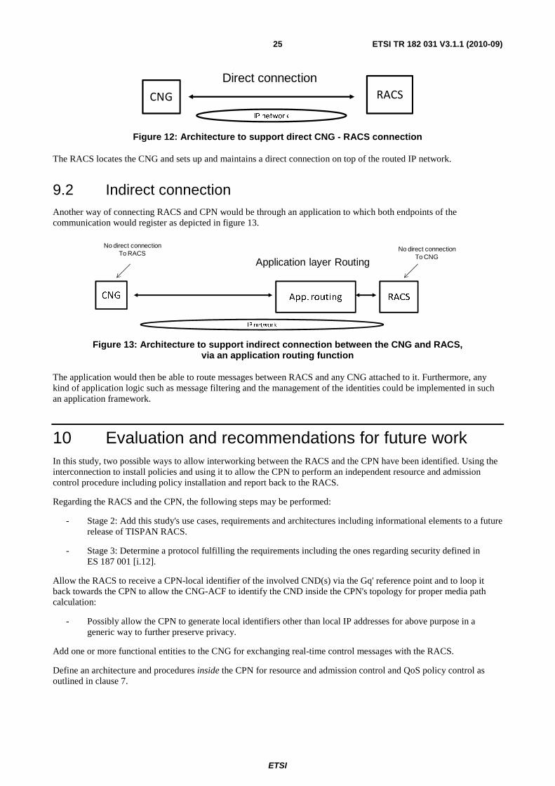
9.2 Indirect connection Another way of connecting RACS and CPN would be through an application to which both endpoints of the communication would register as depicted in figure 13.
RACSApp. routingCNG
IP network
Application layer RoutingNo direct connection
To CNG
No direct connectionTo RACS
Figure 13: Architecture to support indirect connection between the CNG and RACS, via an application routing function
The application would then be able to route messages between RACS and any CNG attached to it. Furthermore, any kind of application logic such as message filtering and the management of the identities could be implemented in such an application framework.
10 Evaluation and recommendations for future work In this study, two possible ways to allow interworking between the RACS and the CPN have been identified. Using the interconnection to install policies and using it to allow the CPN to perform an independent resource and admission control procedure including policy installation and report back to the RACS.
Regarding the RACS and the CPN, the following steps may be performed:
- Stage 2: Add this study's use cases, requirements and architectures including informational elements to a future release of TISPAN RACS.
- Stage 3: Determine a protocol fulfilling the requirements including the ones regarding security defined in ES 187 001 [i.12].
Allow the RACS to receive a CPN-local identifier of the involved CND(s) via the Gq' reference point and to loop it back towards the CPN to allow the CNG-ACF to identify the CND inside the CPN's topology for proper media path calculation:
- Possibly allow the CPN to generate local identifiers other than local IP addresses for above purpose in a generic way to further preserve privacy.
Add one or more functional entities to the CNG for exchanging real-time control messages with the RACS.
Define an architecture and procedures inside the CPN for resource and admission control and QoS policy control as outlined in clause 7.

ETSI
ETSI TR 182 031 V3.1.1 (2010-09) 26
Annex A: Comparable work in other standardization bodies
A.1 ITU-T NOTE: During the study period, ITU-T had two open work items regarding a similar interaction of a centralized
resource and admission control system (ITU RACF) with the CPN:
- ITU-T draft Recommendation Q.3308 Resource control protocol 8 (rcp8) Protocol at the interface between Resource Admission Control Physical Entity (RAC-PE) and CPN Gateway Policy Enforcement Physical Entities (CGPE-PE ) (Rh interface).
- ITU-T draft Recommendation Q.3310 Resource control protocol X (rcpX) Protocol at the interface between Resource Admission Control Physical Entity (RAC-PE) and CPN Gateway Policy Decision Physical Entities (CGPD-PE) (Rh' interface).

ETSI
ETSI TR 182 031 V3.1.1 (2010-09) 27
Annex B: Implementation examples
B.1 H(e)NB Implementation Scenario
B.1.1 Implementation Scenario Overview
A H(e)NB is a customer-premises equipment that connects a 3GPP UE over the EUTRAN wireless air interface to a mobile operator's network using broadband IP backhaul (see TS 122 220 [i.9], 3GPP TR 23.830 [i.10] and TS 125 467 [i.11]), using the backhaul capabilities of the NGN WAN. Wireless access terminates in the H(e)NB. A H(e)NB is authenticated, authorized and administrated by a 3GPP mobile operator who may or may not coincide with the provider roles defined in TS 181 005 [i.13].
In the scenario described here, a 3GPP mobile terminal is attached to a H(e)NodeB inside the CPN. The H(e)NB uses an encrypted tunnel to connect to the gateway in the wireless core network.
CNG
Accessline
CPN
H(e)NB
Fixed-line
access,
aggregation
and core
networkAN
Wireless
core
network
UE
Gate-
way
Figure B.1: H(e)NB scenario
A multimedia session (e.g. a voice call or a video session) is to be set up. To assure the service quality and to allow the flow, resources need to be reserved in the fixed line network and inside the CPN. Furthermore, the traffic needs to be classified based on flow characteristics in order to allow proper packet treatment in the transport plane. Since the traffic from the H(e)NodeB is transported in an encrypted tunnel, there is no possibility for the CNG to detect the traffic using as an example ALGs or static QoS policies based on e.g. port numbers.
B.1.2 Possible solution
To allow for resource reservation and policy installation in the fixed line access network and the CPN, the RACS needs to receive a request from the policy controller in the wireless core network. The RACS will take care of resources in the access, aggregation and core network of the fixed line network while it connects to the CNG in order to allow for resource reservation and policy installation in the CPN and on the access line as depicted in figure B.2.

ETSI
ETSI TR 182 031 V3.1.1 (2010-09) 28
CNG
Accessline
CPN
H(e)NB
Fixed-line
access,
aggregation
and core
networkAN
Wireless
core
network
UE
Wireless network
policy controller
RACS
H-RAC
(3)(2) (4)
(1) (5)
Gate-
way
Figure B.2: H(e)NB scenario including control plane for resource control
Once the UE has sent a setup message for a new multimedia session through the H(e)NB to the wireless core network, the steps to be executed are as follows:
1) The wireless network's policy controller requests resources from the RACS.
2) The RACS requests resource reservation and policy installation inside the CPN and on the access line.
3) The RACS requests resource reservation and policy installation from the access node.
4) The RACS requests resource reservation and policy installation from the fixed line access, aggregation and core network.
5) The RACS reports back to the requesting policy controller from the wireless network.
This allows for end-to-end dynamic QoS control including CNG and CPN.
B.2 Untrusted non-3GPP access to 3GPP core network implementation Scenarios
This clause describes an implementation scenario for QoS in the CPN and on the access line where a 3GPP UE roams into the TISPAN CPN using the 3GPP's untrusted non-3GPP access model.
B.2.1 Implementation Scenario Overview
In the untrusted non-3GPP access model, a 3GPP UE sets up an IPSec tunnel towards the ePDG in the 3GPP operator's core network. After that, all signalling and data plane traffic traverses this tunnel (see TS 123 402 [i.14]). As prerequisite, the UE needs to have obtained a local IP address from the CNG and has to discover the ePDG.

ETSI
ETSI TR 182 031 V3.1.1 (2010-09) 29
Figure B.3: Untrusted non-3GPP access to a 3GPP core network using TISPAN NGN through a CPN
As depicted in figure B.3, the UE uses resources in the CPN and the NGN fixed-line access network.
B.2.2 Possible Solution
To allow for QoS reservations and policy installation in the fixed line access and the CPN, an interworking solution between fixed line and mobile network control plane needs to be defined, which is out of scope of this study.
The RACS-CPN interaction can nevertheless, provide the "broken link" regarding end-to-end guaranteed QoS towards the ePDG as depicted in the steps shown in figure B.4.
Figure B.4: Untrusted non-3GPP access to 3GPP core network using TISPAN NGN through a CPN with policy control interworking

ETSI
ETSI TR 182 031 V3.1.1 (2010-09) 30
In order to provide guaranteed QoS, the PCRF receives requests from the bearer plane (initial setup, modification or tear down of a bearer, from PDN Gateway via Gx reference point) and/or from the application plane (initial setup, modification or tear down of an application session, from an AF via the Rx reference point).
The PCRF can then perform the same steps as depicted in the Home(e)NodeB implementation scenario to allow the provisioning of guaranteed QoS including the access line and the resources inside the CPN:
1) The PCRF requests resources from the RACS.
2) The RACS requests resource reservation and policy installation inside the CPN and on the access line.
3) The RACS requests resource reservation and policy installation from the access node.
4) The RACS requests resource reservation and policy installation from the fixed line access, aggregation and core network.
5) The RACS reports back to the PCRF.
While steps 1, 3, 4 and 5 are out of scope of this study, the RACS-CPN interaction in step 2 can assure guaranteed QoS inside CPN and on the access line using the procedures studied in the present document.

ETSI
ETSI TR 182 031 V3.1.1 (2010-09) 31
History
Document history
V3.1.1 September 2010 Publication

![TR 182 030 - V3.1.1 - Telecommunications and Internet ... 7 ETSI TR 182 030 V3.1.1 (2011-05) [i.26] ETSI TS 182 019: "Telecommunications and Internet converged Services and Protocols](https://static.fdocuments.in/doc/165x107/5b2ec97d7f8b9ac06e8cc8d2/tr-182-030-v311-telecommunications-and-internet-7-etsi-tr-182-030-v311.jpg)