TR 101 118 - V01.01.01 - Network Aspects (NA); High level ...€¦ · European Telecommunications...
58
European Telecommunications Standards Institute TR 101 118 V1.1.1 (1997-11) Technical Report Network Aspects (NA); High level network architectures and solutions to support number portability
Transcript of TR 101 118 - V01.01.01 - Network Aspects (NA); High level ...€¦ · European Telecommunications...

European Telecommunications Standards Institute
TR 101 118 V1.1.1 (1997-11)Technical Report
Network Aspects (NA);High level network architectures
and solutions to supportnumber portability
TR 101 118 V1.1.1 (1997-11)2
ReferenceDTR/NA-020064 (aco00ics.PDF)
Keywordsportability
ETSI Secretariat
Postal addressF-06921 Sophia Antipolis Cedex - FRANCE
Office address650 Route des Lucioles - Sophia Antipolis
Valbonne - FRANCETel.: +33 4 92 94 42 00 Fax: +33 4 93 65 47 16
Siret N° 348 623 562 00017 - NAF 742 CAssociation à but non lucratif enregistrée à laSous-Préfecture de Grasse (06) N° 7803/88
X.400c= fr; a=atlas; p=etsi; s=secretariat
[email protected]://www.etsi.fr
Copyright Notification
No part may be reproduced except as authorized by written permission.The copyright and the foregoing restriction extend to reproduction in all media.
© European Telecommunications Standards Institute 1997.All rights reserved.

TR 101 118 V1.1.1 (1997-11)3
Contents
Intellectual Property Rights................................................................................................................................7
Foreword ............................................................................................................................................................7
1 Scope........................................................................................................................................................8
2 References................................................................................................................................................8
3 Definitions, symbols and abbreviations...................................................................................................83.1 Definitions ......................................................................................................................................................... 83.2 Abbreviations................................................................................................................................................... 11
4 Definition of number portability............................................................................................................11
5 General assumptions and requirements on number portability..............................................................125.1 Assumptions..................................................................................................................................................... 125.2 Requirements ................................................................................................................................................... 12
6 High level evolutionary network models to support call set-up when service provider portabilityis allowed for geographic numbers ........................................................................................................12
6.1 Background information .................................................................................................................................. 126.2 General introduction to described models........................................................................................................ 136.3 Call re-routing initiated/performed by donor network ..................................................................................... 136.3.1 Call Re-routed from Donor Network by use of Onward Routeing principles ............................................ 146.3.1.1 General Description.............................................................................................................................. 146.3.1.2 Interaction with supplementary services............................................................................................... 146.3.1.3 Interaction with IN based services........................................................................................................ 146.3.1.4 Interaction with carrier selection .......................................................................................................... 146.3.1.5 Interaction with statistical counters....................................................................................................... 156.3.1.6 Required forward information transfer between networks.................................................................... 156.3.1.7 Required backward information transfer between networks.................................................................156.3.1.8 NP Routeing loop detection issues ....................................................................................................... 156.3.1.9 Pros....................................................................................................................................................... 166.3.1.10 Cons...................................................................................................................................................... 166.3.2 Call re-routed by drop-back principles from donor network ...................................................................... 166.3.2.1 General description............................................................................................................................... 166.3.2.2 Interaction with supplementary services............................................................................................... 176.3.2.3 Interaction with IN based services........................................................................................................ 186.3.2.4 Interaction with carrier selection .......................................................................................................... 186.3.2.5 Interaction with statistical counters....................................................................................................... 186.3.2.6 Required forward information transfer between networks.................................................................... 186.3.2.7 Required backward information transfer between networks.................................................................186.3.2.8 NP routeing loop detection issues......................................................................................................... 186.3.2.9 Pros....................................................................................................................................................... 186.3.2.10 Cons...................................................................................................................................................... 196.3.3 Call re-routing initiated by "Query on Release (QoR)" principles from donor network ............................ 196.3.3.1 General description............................................................................................................................... 196.3.3.2 Interaction with supplementary services............................................................................................... 206.3.3.3 Interaction with IN based services........................................................................................................ 216.3.3.4 Interaction with carrier selection .......................................................................................................... 216.3.3.5 Interaction with statistical counters....................................................................................................... 216.3.3.6 Required forward information transfer between networks.................................................................... 216.3.3.7 Required backward information transfer between networks.................................................................216.3.3.8 NP Routeing loop detection issues ....................................................................................................... 216.3.3.9 Pros....................................................................................................................................................... 216.3.3.10 Cons...................................................................................................................................................... 226.4 Call re-routing initiated/performed by transit network prior to donor network................................................ 226.4.1 Re-routing initiated by reception of re-routing information from succeeding network .............................. 226.4.2 Re-routing initiated by reception of "number ported-out information" from succeeding network ............. 22

TR 101 118 V1.1.1 (1997-11)4
6.4.3 Re-routing initiated by "all call query one step" principles........................................................................ 226.4.3.1 General description............................................................................................................................... 226.4.3.2 Interaction with supplementary services............................................................................................... 236.4.3.3 Interaction with IN based services........................................................................................................ 236.4.3.4 Interaction with carrier selection .......................................................................................................... 236.4.3.5 Interaction with statistical counters....................................................................................................... 236.4.3.6 Required forward information transfer between networks.................................................................... 236.4.3.7 Required backward information transfer between networks.................................................................236.4.3.8 NP routeing loop detection issues......................................................................................................... 236.4.3.9 Pros....................................................................................................................................................... 236.4.3.10 Cons...................................................................................................................................................... 246.5 Call re-routing performed by originating network ........................................................................................... 246.5.1 Re-routing initiated by reception of re-routing information from succeeding network .............................. 246.5.2 Re-routing initiated by reception of "number ported-out information" from succeeding network ............. 246.5.3 Re-routing initiated by "All call query one step" principles....................................................................... 246.5.3.1 General description............................................................................................................................... 246.5.3.2 Interaction with supplementary services............................................................................................... 256.5.3.3 Interaction with IN based services........................................................................................................ 256.5.3.4 Interaction with carrier selection .......................................................................................................... 256.5.3.5 Interaction with statistical counters....................................................................................................... 256.5.3.6 Required forward information transfer between networks.................................................................... 256.5.3.7 Required backward information transfer between networks.................................................................256.5.3.8 NP Routeing loop detection issues ....................................................................................................... 256.5.3.9 Pros....................................................................................................................................................... 256.5.3.10 Cons...................................................................................................................................................... 266.6 Call re-routing to recipient performed by a two step number translation principle.......................................... 266.6.1 General description .................................................................................................................................... 266.6.2 Interaction with supplementary services..................................................................................................... 286.6.3 Interaction with IN based services ............................................................................................................. 286.6.4 Interaction with carrier selection ................................................................................................................ 286.6.5 Interaction with statistical counters ............................................................................................................ 296.6.6 Required forward information transfer between networks ......................................................................... 296.6.7 Required backward information transfer between networks....................................................................... 296.6.8 NP routeing loop detection issues .............................................................................................................. 296.6.9 Pros ............................................................................................................................................................ 296.6.10 Cons ........................................................................................................................................................... 296.7 Call re-routing performed by using "all call query all involved networks" principles ..................................... 306.7.1 General description .................................................................................................................................... 306.7.2 Interaction with supplementary services..................................................................................................... 306.7.3 Interaction with IN based services ............................................................................................................. 306.7.4 Interaction with carrier selection ................................................................................................................ 306.7.5 Interaction with statistical counters ............................................................................................................ 306.7.6 Required forward information transfer between networks ......................................................................... 316.7.7 Required backward information transfer between networks....................................................................... 316.7.8 NP routeing loop detection issues .............................................................................................................. 316.7.9 Pros ............................................................................................................................................................ 316.7.10 Cons ........................................................................................................................................................... 31
7 Examples of locations of number portability data base(-s) within networks.........................................327.1 General description.......................................................................................................................................... 327.2 Network overview for geographic numbers ..................................................................................................... 337.3 NP re-routing data stored in donor network..................................................................................................... 347.3.1 NP re-routing data stored in donor local exchange .................................................................................... 347.3.1.1 General description............................................................................................................................... 347.3.1.2 Interaction with supplementary services............................................................................................... 347.3.2 NP re-routing data stored in donor network transit exchanges................................................................... 347.3.2.1 General description............................................................................................................................... 347.3.2.2 Interaction with supplementary services............................................................................................... 357.3.3 NP re-routing data stored in donor network GW exchanges ...................................................................... 357.3.4 Re-routing data stored exchange external in donor network ...................................................................... 367.3.4.1 General description............................................................................................................................... 36
TR 101 118 V1.1.1 (1997-11)5
7.3.4.2 Query to central database by donor local exchange.............................................................................. 367.3.4.2.1 General description ......................................................................................................................... 367.3.4.2.2 Interaction with supplementary services ......................................................................................... 367.3.4.3 Query to central database by donor transit exchange(-s) ...................................................................... 367.3.4.3.1 General description ......................................................................................................................... 367.3.4.3.2 Interaction with supplementary services ......................................................................................... 377.3.4.4 Query to central database by both donor local, transit and gateway exchange(-s)................................ 377.3.4.4.1 General description ......................................................................................................................... 377.3.4.4.2 Interaction with supplementary services ......................................................................................... 377.4 NP re-routing data stored/ accessed in transit network .................................................................................... 387.4.1 NP re-routing data stored/accessed in transit network gateway exchange(-s) ............................................ 387.4.2 NP re-routing data stored/accessed centrally and accessed by transit network .......................................... 387.4.2.1 General description............................................................................................................................... 387.5 NP re-routing data stored in originating network............................................................................................. 397.5.1 NP re-routing data stored centrally and accessed by originating network.................................................. 397.5.1.1 General description............................................................................................................................... 397.6 NP re-routing data stored in recipient network ................................................................................................ 40
8 High level evolutionary model for np and sccp using services to geographic numbers ........................418.1 Background information .................................................................................................................................. 418.2 Requirements on solutions for routeing of SCCP messages............................................................................. 418.3 Proposal for solutions ...................................................................................................................................... 428.4 General introduction to described models........................................................................................................ 428.4.1 SCCP routeing solutions in donor network/exchange ................................................................................ 438.4.1.1 General description............................................................................................................................... 438.4.1.2 Pros....................................................................................................................................................... 438.4.1.3 Cons...................................................................................................................................................... 438.4.2 SCCP routeing solutions in originating network/exchange ........................................................................ 448.4.2.1 General description............................................................................................................................... 448.4.2.2 Pros....................................................................................................................................................... 448.4.2.3 Cons...................................................................................................................................................... 448.4.3 SCCP routeing solutions in originating and recipient network/exchange................................................... 458.4.3.1 General description............................................................................................................................... 458.4.3.2 Pros....................................................................................................................................................... 458.4.3.3 Cons...................................................................................................................................................... 45
9 Proposed generic distributed functional entity model for number portability.......................................469.1 General information ......................................................................................................................................... 469.2 Call Control Functions (CCF).......................................................................................................................... 479.3 Call Control Portability Functions (CCPF)...................................................................................................... 479.4 Number Portability Control Functions (NPCF) ............................................................................................... 479.5 Number Portability Data Functions (NPDF).................................................................................................... 479.6 Number Portability Management Functions (NPMF)...................................................................................... 489.7 Master Number Portability Management Functions (M-NPMF) .....................................................................48
10 Service Provider Portability for Non-Geographic Numbers (NGNP) ...................................................48
11 Concatenation of service provider portability for Non-Geographic Numbers (NGNP) andGeographic Numbers (GNP)..................................................................................................................48
12 High Level examples for management of NP information ....................................................................4912.1 General Description ......................................................................................................................................... 4912.2 NP data is donor network internal business ..................................................................................................... 4912.3 NP data is centrally managed per portability domain ...................................................................................... 5112.4 NP data is centrally managed on national level ............................................................................................... 5212.5 NP data is centrally managed on European level ............................................................................................. 52
Annex A ................................................................................................................................................53
A.1 Current proposals on solutions for Number Portability.........................................................................53A.1.1 Introduction...................................................................................................................................................... 53A.1.2 Simple Call Forwarding Unconditional (CFU) ................................................................................................ 54A.1.3 Remote Call Forwarding (RCF)....................................................................................................................... 54

TR 101 118 V1.1.1 (1997-11)6
A.1.4 Return To Pivot (RTP)..................................................................................................................................... 54A.1.5 Query on Release (QoR).................................................................................................................................. 55A.1.6 Call Completion to Portable Number (CCPN)................................................................................................. 55A.1.7 Local Area Number Portability (LANP).......................................................................................................... 56A.1.8 Carrier Portability Code (CPC)........................................................................................................................ 56A.1.9 Network Routeing Prefix (NRP)...................................................................................................................... 56A.1.10 Generic Routeing Method (GRM) ................................................................................................................... 57
History ..............................................................................................................................................................58

TR 101 118 V1.1.1 (1997-11)7
Intellectual Property RightsIPRs essential or potentially essential to the present document may have been declared to ETSI. The informationpertaining to these essential IPRs, if any, is publicly available for ETSI members and non-members, and can be foundin ETR 314: "Intellectual Property Rights (IPRs); Essential, or potentially Essential, IPRs notified to ETSI in respect ofETSI standards", which is available free of charge from the ETSI Secretariat. Latest updates are available on the ETSIWeb server (http://www.etsi.fr/ipr).
Pursuant to the ETSI Interim IPR Policy, no investigation, including IPR searches, has been carried out by ETSI. Noguarantee can be given as to the existence of other IPRs not referenced in ETR 314 (or the updates onhttp://www.etsi.fr/ipr) which are, or may be, or may become, essential to the present document.
ForewordThis Technical Report (TR) has been produced by ETSI Technical Committee Network Aspects (NA).
TR 101 118 V1.1.1 (1997-11)8
1 ScopeThe present document is to investigate, address and describe possible High level Network Architectures and Solutionsfor Number Portability of ITU-T Recommendation E.164 [3] numbers in the fixed telecommunications Network.
The following is included in the present document:
a) possible Network Architectures and solutions to support number portability;
b) Pros and Cons for described Number Portability solutions and influences on services;
c) management issues with regard to NP and selected Data Base solution;
d) the exchange of NP related information between Networks per solution;
e) routeing issues with relation to NP and described solution.
The following types of number portability is to be covered:
1) service provider portability of Geographic Numbers;
2) service provider portability of Non Geographic Numbers.
NP solutions both for Routeing of ordinary calls and for Routeing of connection less supplementary services (e.g.CCBS) are included.
2 ReferencesReferences may be made to:
a) specific versions of publications (identified by date of publication, edition number, version number, etc.), inwhich case, subsequent revisions to the referenced document do not apply; or
b) all versions up to and including the identified version (identified by "up to and including" before the versionidentity); or
c) all versions subsequent to and including the identified version (identified by "onwards" following the versionidentity); or
d) publications without mention of a specific version, in which case the latest version applies.
A non-specific reference to an ETS shall also be taken to refer to later versions published as an EN with the samenumber.
[1] ITU-T Recommendation E.164: "International telecommunications numbering plan".
3 Definitions, symbols and abbreviations
3.1 DefinitionsFor the purposes of the present document the following definitions apply:
In the following a number of definitions are listed, for used but not included definitions please see TR: "High LevelDescription of Number Portability".
Data Base (DB): A DB is, within the present document, the storage place where a translation of a Portable Number to aRouteing Number (RN) takes place. Other NP related information might exist in same place. The other informationmight be of either traffical or administrative nature. The other traffical information might be retrieved/used at same timeas retrieving the RN.

TR 101 118 V1.1.1 (1997-11)9
The DB might be located exchange internal or external depending on Network solution.
Directory Number (DN): A DN is a number in the national numbering scheme that is allocated to a customer for atelephony service. Allocation of the DN is either made directly by the Numbering Plan Administration (NPA) to thecustomer, or indirectly when blocks of numbers are managed by Service Providers. The DN is the number that is dialledby the users to reach the customer (potentially with prefix and/or with suffix).
donor exchange: A donor exchange is the initial exchange where a number was located before ever being ported.
donor network: donor network is the initial network where a number was allocated by the NPA before ever beingported.
donor service provider: A donor service provider is the service provider from whom the number is ported.
essential service: An essential service is a service that should be executed to allow the call to be continued. Examples ofessential services are User to User 1 essential and Closed User Group without outgoing access allowed.
The service is considered not possible to execute when transfer of the service related data is not possible, e.g. toprotocol limitations or bilateral agreements.
Gateway Exchange (GW): A GW is, within the present document, an Exchange that has Point of Interconnection(-s) toExchange(-s) in other Networks.
Geographic Number (GN): A GN is a DN from that part of the national numbering scheme that is used to identifyfixed line termination. Prior to Number portability these numbers are geographical in that sense that they conveyed thedetailed location of the customer.
Geographic Number Portability (GNP): See Service Provider Portability for Geographic Numbers.
Network Operator: A Network Operator is an entity that operates public telecommunications network in order to routecalls.
Non Geographic Number (NGN): NGN is a Directory number that is not a Geographic Number. A Non-geographicNumber does not imply the Geographic location of the customer.
Non Geographic Number Portability (NGNP): See Service Provider Portability for Non Geographic Numbers.
Number overview: The Table 1 below shows a simplified overview of Numbers involved in Number Portability, it alsoexemplifies Non-Geographic Numbers.
Table 1: Relationship between Geographic and Non Geographic Numbers
DIRECTORY NUMBERGEOGRAPHIC NUMBER NON-GEOGRAPHIC NUMBER
ETNS Number Mobile Number Service Number Other NonGeographicNumber
NOTE: These are examples of non geographic numbers only, and are not prescriptive1
Mobile Number: A Mobile Number (MN) is a Directory Number from a specific range of the national numberingscheme reserved for customers to mobile service(s). MN Portability is outside the scope of this report.
Onward Routeing Exchange (ORE): An Onward Routeing Exchange is, within this document, an Exchange within anOnward Routeing Network (ORN) that makes use of a Routeing Number to route a call onward towards a RecipientNetwork/Exchange.
Onward Routeing Network (ORN): An Onward Routeing Network (ORN) is, within this document, a Network thatmakes use of a Routeing Number to route a call onward towards a Recipient Network/Exchange.
Originating Exchange: Originating Exchange IS the Exchange where the calling party is located.
For most incoming international calls, the Originating Exchange is effectively the international gateway Exchange.

TR 101 118 V1.1.1 (1997-11)10
For carrier selection, the first exchange of the selected carrier effectively becomes the Originating Exchange for routeingpurposes.
Originating Network: Originating Network is the network where the calling party is connected.
For most incoming international calls, the originating network is effectively the network containing the internationalgateway.
For carrier selection, the first exchange of the selected carrier effectively becomes the originating network for routeingpurposes.
Portable Number (PN): A PN)is, within the present document, a DN that a subscriber can port when changing ServiceProvider.
A PN can e.g. have one of the following statuses:
a) vacant and not ported;
b) used and not ported;
c) ported.
A Ported Number is both Ported-in (Recipient Network) and Ported-out Donor Network) at the same time.
Ported Number: A number that has been subject to number portability.
Ported-in Number: A ported-in number is, within this document, a Portable Number that has been ported into aRecipient Network/Exchange.
Ported-out Number: A ported-out number is, within this document, a Portable Number that has been ported out of aDonor Network/Exchange.
Recipient Exchange: A Recipient Exchange is the new Exchange where a number is located after being ported.
Recipient Network: Recipient Network is the Network where a number is located after being ported.
Recipient Service Provider: A Recipient Service Provider is the Service Provider to whom the number is ported.
Routeing Global Title (RGT): A Routeing Global Title (RGT) is, within this document, obtained from a NP DB byusing a Called Party Number as input, it is used to route a connection less service towards Recipient Network or/andRecipient Exchange.
Routeing Number (RN): A Routeing Number is, within this document, a specific number that is added and used by thenetworks to route the call. The Routeing Number conveys information usable by the network. If the digits dialled by theuser match the digits of a routeing number, the dialled digits should not be interpreted as a routeing number.
Service Provider (SP): A Service Provider is an entity that offers services to users involving the use of networkresources. The "Service Provider" is understood in this document in a generic way and may have different statusaccording to the service he provides. For example, "Service Provider" refers to a local loop operator in the case ofGeographic Numbers, or to a mobile operator in the case of Mobile Numbers, or to a service operator / reseller in thecase of Service Numbers.
Service Provider Portability for Geographic Numbers: Service Provider Portability for Geographic Numbers is aservice that enables customers to resign their subscription with a Service Provider (Donor) and to contract anothersubscription with another Service Provider (Recipient) without changing their Geographic Number, without changingtheir location, and without changing the nature of the service offered.
This service is also known as GNP and also known as Local Number Portability (LNP).
Service Provider Portability for Non geographic Numbers (NGNP): Service Provider Portability for NGNP is aservice that enables customers to resign their subscription with a Service Provider (Donor) and to contract anothersubscription with another Service Provider (Recipient) without changing their Non-geographic Number, and withoutchanging the nature of the service offered.
This service is also known as NGNP.

TR 101 118 V1.1.1 (1997-11)11
Service Provider Portability for Pan-European Services: Service Provider Portability for Pan-European Services is aservice that enables a user to resign their subscription with their current Pan European Service Provider and subscribe toa competitor without changing their pan European Service Number.
Serving Exchange (SE): A Serving Exchange (SE) is, within this document, an Exchange within a Serving Network(SN) that makes a data base (Exchange internal or external) access to retrieve Routeing Number for a call to a PortableNumber.
Serving Network (SgN): A Serving Network (SgN) is, in this document, a Network that makes a data base (Networkinternal or external) access to retrieve Routeing Number for a call to a Portable Number, i.e. it determines whether anumber has been ported, and, if so, provides an appropriate routeing number. This functionality may be distributed.
Signalling Point with Relay(SPR): A SPR consists of both the MTP and SCCP layers of ITU-T Signalling Systemnumber 7.
Transit Exchange: A Transit Exchange is an exchange between two exchanges, e.g. between the recipient exchangeand the donor exchange.
Transit Network: Transit Network is a network between two networks, e.g. between the Recipient and the DonorNetworks.
3.2 AbbreviationsFor the purposes of the present document the following abbreviations apply:
In the following a number of document internal Symbols and Abbreviations are listed, for not included Symbols andAbbreviations please see "TR: High Level Description of Number Portability.
CCPF Call Control Portability FunctionsCFB Call Forwarding BusyCFNR Call Forwarding No ReplyCFU Call Forwarding UnconditionalCS Carrier SelectionDB Data BaseDN Directory NumberGNP Geographic Number PortabilityETNS European Telephony Numbering SpaceMSISDN Mobile Station ISDNISPBX ISDN PBXNGNP Non Geographic Number PortabilityNPA Numbering Plan AdministrationNPCP Number Portability Control PointNPDP Number Portability Data PointNPMF Number Portability Management FunctionsPBX Private Branch ExchangePN Personal NumberRN Routeing NumberSCP Service Control PointSSP Service Switching PointSSCP Service Switching and Control PointSPR Signalling Point with Relay functionsSTP Signalling Transfer PointUAN Universal Access NumberUPT Universal Personal TelecommunicationsVPN Virtual Private Network
4 Definition of number portabilityFor the definition and scope of Number Portability please see TR: "High Level Description of Number Portability".

TR 101 118 V1.1.1 (1997-11)12
5 General assumptions and requirements on numberportability
5.1 AssumptionsThe following document internal assumptions have been made:
a) that Calling Line Identity (CLI) is required to be transported, with display information, unchanged to RecipientNetwork;
b) that Connected Line Identity (COLI) is required to be transported, with display information, unchanged toOriginating Network;
c) that Initial Routeing arrangements have been defined and implemented prior the introduction of Routeing basedon a Routeing Number;
d) it is assumed that Number Portability is not allowed to influence the carrier selection function;
e) It is assumed that a NP solution shall not influence functions in Private Branch Exchange (PBX's);
f) porting (i.e. reallocation) of complete number blocks is outside this report, works already.
For other General assumptions on Number Portability please see TR: " High Level Description of Number Portability".
5.2 RequirementsIt is required that a High Level Network Architecture for Number Portability allows Network Operator(-s) freedom andprivacy in the arrangement of the Network internals as long as the external requirements are fulfilled. Externalrequirements to a Network could be e.g. supplementary service level transparency, post dialling delay, robustness andduration to support porting of Portable Numbers.
Number Portability data distribution aspects is also considered, this to allow evolution, smooth portability, safety andprivacy.
For other Requirements on Number Portability please see TR: "High Level Description of Number Portability".
6 High level evolutionary network models to supportcall set-up when service provider portability isallowed for geographic numbers
6.1 Background informationTo ease Routeing tables in the current Public Telecommunications networks (PSTN and ISDN), ITU-TRecommendation E.164 [3] numbers are normally handled and allocated to geographic areas in blocks of e.g. 10.000subscriber numbers. Each of the blocks are then given to the care of one network provider. The network Operator theneither allocates the full 10.000 block or parts of it (e.g. in sub blocks of 1.000 numbers) to a particular Local Exchange(LE), i.e. all subscribers having a subscriber number within a certain block may only be connected to the (local)Exchange handling the number block in question. An other fact has been that a subscriber moving into a new geographicarea may only receive a number within the number block(-s) maintained by the new serving operator and new localExchange to be connected to.
The Routeing of a call to subscriber part of PSTN/ISDN, is normally done based on the 10.000 number block the calledsubscriber number is part of. This traditional principle for Routeing of a call will need to change when introducingService Provider Portability of Geographic Numbers, since the number series that the called number is part of will nolonger have a relation to a particular operators network.

TR 101 118 V1.1.1 (1997-11)13
6.2 General introduction to described modelsThe following subclauses describes a high level evolutionary model for Service Provider Portability for GeographicNumbers. Non Geographic Numbers within scope of this report, is covered by own chapters.
The drawings in the figures and the descriptions are focused on:
a) the location in the telecommunications Network where NP information is maintained and stored, i.e. place of DB;
b) the location in the telecommunications Network where NP actions are initiated/triggered;
c) the location in the telecommunications Network where NP data is retrieved, i.e. place of DB query;
d) the location in the telecommunications Network where NP data is used for call Routeing;
e) interconnection issues.
NOTE: The emphasis on placing the NP DB in the figures is from where the DB access is performed and whattriggered the DB access. Despite the figures show the location of the DB within the domain of a particularNetwork it shall be understood that the DB might very well be located outside that domain, e.g. commonlymaintained by a third party.
Four main types of Networks are described and identified as involved (depending on the level of NP evolution in theNetworks concerned) in setting up a call to a ported subscriber:
1) Originating Network;
2) Transit Network;
3) Donor Network;
4) Recipient Network.
NOTE: For most incoming International call the Originating Network will be the Network containing theincoming international gateway. The similar is applied for an incoming call from a PLMN, i.e. that thefirst incoming GW exchange in the fixed network is regarded as Originating Exchange unless the PLMNhas NP DB query capabilities also for Numbers belonging to the fixed network.
Despite that management functions not are shown in the figures one should understand that such exist. The managementfunctions might, depending on choices of solutions, be grouped in four areas:
A) Management of all the national numbers (i.e. all NP domains in a country);
B) Management of a single NP domain (e.g. domain of an Area code);
C) Management of NP within a Network providers domain;
D) Management of NP within a Network element (e.g. domain of a LE).
Depending on solution one, two or all four areas of management functions might exist. The Management functions forNumber Portability are modelled and described in later chapters.
It shall be understood that other signalling systems than ISUP can be used despite arrows, e.g. IAM and REL, in thefigures uses abbreviations that exist in the ISUP protocol.
The main discussions around loop and NP DB mismatch detection in run time is described in TR: " Numbering andAddressing for Number Portability".
6.3 Call re-routing initiated/performed by donor networkThis subclause intends to describe possible High Level NP solutions in a Donor Network.

TR 101 118 V1.1.1 (1997-11)14
6.3.1 Call Re-routed from Donor Network by use of Onward Routeingprinciples
6.3.1.1 General Description
The first step/solution discussed for Number Portability is often that the Donor Network maintains the portabilityinformation, i.e. the complete Address to both Recipient Network and Exchange, for ported-out numbers and rerouteincoming calls to ported-out numbers Onward towards the Recipient Network according to Onward Routeing principlesoutlined in figure 1.
IA M
a1 ) IA M
a2 ) IA M
b ) IA M
IA M
O r ig in a tin gN e tw o r k
C a llin g S u b s c r ib e r
D o n o rN e tw o r k
R e c ip ie n tN e tw o r k
C a lle d S u b s c r ib e r
T r a n s i tN e tw o r k ( - s ) ( B )
D B
Tr a n s i tN e tw o r k ( - s ) ( A )
Figure 1: Call Re-routing to Recipient Network by Onward Routeing principles from Donor Network
In figure 1, the Donor Network receives an Incoming call. It then detects that the called number has been ported-out toanother network, makes a DB query to retrieve a Routeing Number. It thereafter reroute the call onward towards theRecipient Network using retrieved Routeing information.
Option a1 and a2 is valid when Donor Network either has no direct interconnection to Recipient Network or whenoverflow traffic is placed via Transit Network B.
The option b is valid when direct interconnection exists between Donor Network and Recipient Network
Despite that the Donor Network acts as a "Onward Routeing" Network to preceding Networks it can use several of theNP techniques within the Network, see later subclauses for this.
Please note that the Transit Network(-s) are optional, i.e. direct interconnections connections between OriginatingNetwork and Donor Network might very well exist and the same also between Donor Network and Recipient Network.Note also that the Transit Network(-s) A and B can be the same depending on network structure and call case.
6.3.1.2 Interaction with supplementary services
The service level between Originating Network and Recipient Network is dependent on the level supported by theDonor Network since this scenario/solution requires that the Donor Network have at least the functionality level as theother involved networks, otherwise it will limit the service level for the ported subscribers i.e. some calls might fail withe.g. reason "incompatible destination", e.g. when a caller has requested User-User-1 essential and this service is notsupported by Donor Network or that the service is not allowed over operator border to Donor.
The use of same inter-exchange protocol within all networks and also that the same interconnection agreements areestablished between all involved Networks would avoid the interference with supplementary services, but it is highlydebatable if possible or even wanted to achieve.
6.3.1.3 Interaction with IN based services
The same is valid as for interactions with supplementary services, i.e. see previous subclause.
6.3.1.4 Interaction with carrier selection
No interaction identified, in the scope of this report.

TR 101 118 V1.1.1 (1997-11)15
6.3.1.5 Interaction with statistical counters
No interaction identified.
6.3.1.6 Required forward information transfer between networks
Routeing Information is mandatory in the forward direction, from Donor Network. The Information is needed to informTransit and Recipient Networks the destination Recipient Network and Recipient Exchange.
In addition to the above there might be an interest of having a separate indication that a database lookup, for NP Re-routing, has been performed, this so that the Transit/Recipient Network(-s) easily can recognize/trap incoming callstowards ported subscribers. On the other hand, the reception of Routeing Number might very well be enough indication.
6.3.1.7 Required backward information transfer between networks
No new NP related data is identified in the backward direction, in the scope of this report.
6.3.1.8 NP Routeing loop detection issues
No additional loop cases identified, this since this solution only involves retrieval of Routeing information once.
TR 101 118 V1.1.1 (1997-11)16
6.3.1.9 Pros
The main advantages with this solution are that:
a) the Donor Network remains being responsible for the number series with ported-out numbers, it also continuesmaintenance of data related to the numbers, this possibly limits the impacts on management systems of Donor;
b) the preceding Networks do not need to know if called number has been ported or not, this possibly limits theimpacts on management systems of Donor;
c) no new forward call indication is needed towards the Donor;
d) possibly limited impact on signalling systems;
e) additional processing capacity is only required for calls to ported-out numbers.
6.3.1.10 Cons
The main disadvantages with this solution are that:
a) the functionality level for the call is dependent on the Donor Network, i.e. calls with essential services (e.g. if U-U-1 essential) not supported by Donor will fail despite supported by other involved Networks. Non essentialservices will be suppressed if not supported by Donor;
b) the Network resources are not used as efficient as for calls to non ported subscribers;
c) new Routeing information is needed in forward direction from Donor towards Recipient Network;
d) call set-up time will differ between calls to ported-out and not ported numbers;
e) the recipient network(-s) should inform donor network(-s) when modifying network internal structure, i.e. it doesnot allow for privacy for Network Operators;
f) there is a risk that the subscriber context capabilities will be exhausted in Donor LE (if NP data is maintainedexchange internal) since more numbers or even number blocks should be maintained to continue having sameamount of subscribers connected.
6.3.2 Call re-routed by drop-back principles from donor network
6.3.2.1 General description
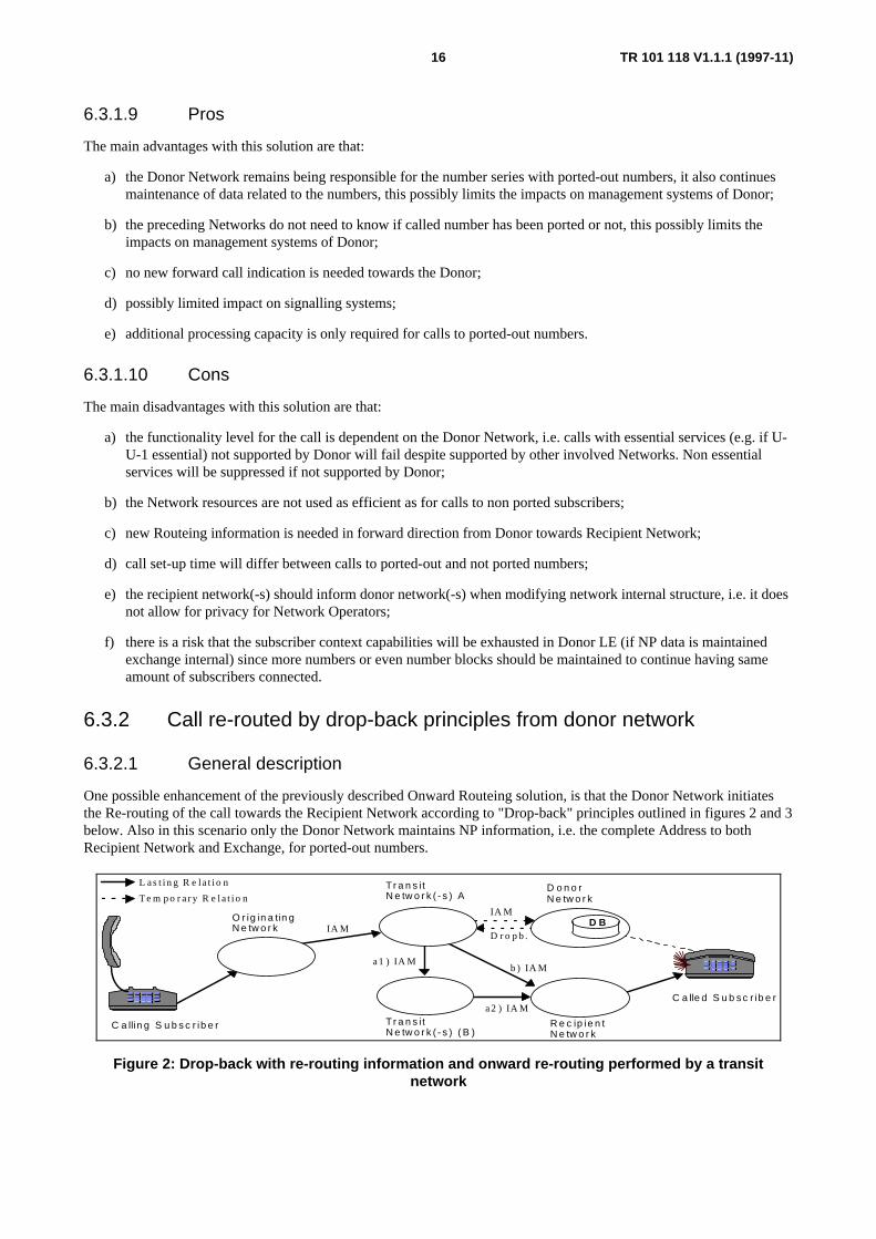
One possible enhancement of the previously described Onward Routeing solution, is that the Donor Network initiatesthe Re-routing of the call towards the Recipient Network according to "Drop-back" principles outlined in figures 2 and 3below. Also in this scenario only the Donor Network maintains NP information, i.e. the complete Address to bothRecipient Network and Exchange, for ported-out numbers.
IA M
b ) IA M a1 ) IA M
O r ig in a tin gN e tw o r k
C a llin g S u b s c r ib e r
D o n o rN e tw o r k
R e c ip ie n tN e tw o r k
C a lle d S u b s c r ib e r
Tr a n s i tN e tw o r k ( - s ) A
D B IA M
D r o p b .
a2 ) IA MTr a n s i tN e tw o r k ( - s ) ( B )
L as t i n g R e la t i o n
T e m p o r a r y R e la t i o n
Figure 2: Drop-back with re-routing information and onward re-routing performed by a transitnetwork

TR 101 118 V1.1.1 (1997-11)17
In figure 2, the Donor Network receives an Incoming call. It then detects that the called number has been ported-out toanother network. It then determines, on basis of received signalling information, that one of the preceding Networks iscapable of handling a "Drop-back" message. It thereafter releases the call with a special indication telling that number isported-out and Re-routing information is enclosed. The transit network then traps the "Drop-back" and reroute the callonward towards the Recipient Network using received backward information.
Option a1 and a2 is valid when Transit Network A either has no direct interconnection to Recipient Network or whenoverflow traffic is placed via Transit Network B.
The option b is valid when direct interconnection exists between Transit Network A and Recipient Network.
IA M
D r o p b . D r o p b .
IA MO r ig in a tin gN e tw o r k
C a llin g S u b s c r ib e r
D o n o rN e tw o r k
C a lle d S u b s c r ib e r
D B
Tr a n s i tN e tw o r k ( - s ) ( A )
b ) IA M
a 1 ) IA M
a 2 ) IA M
Tr a n s i tN e tw o r k ( - s ) ( B )
L a s t i n g R e la t i o n
T e m p o r a r y R e la t i o n
R e c ip ie n tN e tw o r k
c 1 ) IA M c 2 ) IA M
Figure 3: Drop-back with re-routing information and onward re-routing performedby the originating network
In figure 3, either the Transit Network A has no "Drop-back" capability or determines that the preceding Network has"Drop-back" capability. It therefore lets the Release pass through to Originating Network. The Originating Network, atreception of the Release reroute the call towards Recipient Network.
Despite that the Donor Network acts as a "Call Drop-back" Network to preceding Networks it can use several of the NPtechniques within its Network, see later subclauses for this.
Please note that the Transit Networks are optional, i.e. direct connections between Originating Network and DonorNetwork might very well exist but on the other hand the Transit Network might exist (case a1 and a2) between theOnward Routeing (Transit or Originating) Network and Recipient Network.
A further evolution of the "Drop-back" principle outlined in the figure 2 is that the Drop-back message is sent back tothe Originating Network as in figure 3. This evolution is mainly of interest if the Originating Network has directinterconnections to other Networks than the Transit Network used in the call attempt to the Donor Network.
Option a1 and a2, in figure 3, is valid when Originating Network either has no direct interconnection to RecipientNetwork or when overflow traffic is placed via Transit Network B.
The option b, in figure 3, is valid when direct interconnection exists between Originating and Recipient Networks.
The option c1 and c2, in figure 3, is required when Carrier Selection is valid for the call i.e. the Originating Networksreuses the Carrier Selection information after reception of Drop-back message. It could be debated if a selected carrier(e.g. TN A in figure 3) is allowed/recommended to transport the drop-back to Originating Network, but it has no optionif it has no redirect on "Drop-back" capability.
6.3.2.2 Interaction with supplementary services
A risk of Interference exists for essential supplementary services since the Donor Network should be reached to getredirection information, i.e. call might be released prior reaching Donor Network. Interference might exist also for nonessential services if the drop-back is not sent back to the Originating exchange.
A way out is that the all involved networks have same interconnection agreements, but this might not be enough e.g. thesame signalling systems should also be used within all networks in the case call should travel until Donor LocalExchange to get Routeing Information.
The "Drop-back" should not be sent through the Exchange that has performed a Call forwarding service like CFU, CallForwarding Busy (CFB) or Call Forwarding No Reply (CFNR) etc. this to avoid unwanted interference with these kindof services.

TR 101 118 V1.1.1 (1997-11)18
6.3.2.3 Interaction with IN based services
The "Drop-back" should not be sent through the Service Switching Point (SSP) that has performed an IN service likePN, Universal Personal Telecommunications (UPT), Virtual Private Network (VPN), Universal Access Number (UAN),etc. this to avoid unwanted interference with these kind of IN based services.
6.3.2.4 Interaction with carrier selection
An identified Interaction with carrier selection is described as option c1 and c2 in figure 3.
6.3.2.5 Interaction with statistical counters
Standards for Circuit quality counters/statistics should be mollified to handle Drop-back conditions, otherwise alarmsmight come for functioning circuits/destinations when number of calls to ported-out numbers are high. I.e. a drop-backmessage should not be handled as an ordinary release before answer.
6.3.2.6 Required forward information transfer between networks
In the forward direction (IAM), towards Donor, there is a need of an indication telling whether or not "Re-routing onDrop-back" is supported or not, this to inform succeeding Network if it should do the Re-routing or if the release can besent backwards i.e. "Drop-back" can only be performed when a preceding Network has functionality to perform Re-routing based on returned Re-routing information.
An option, not requiring the indication, is the use of bilateral agreements, e.g. a route indicator telling if precedingNetwork has the QoR capability.
An other option, not requiring the indicator, is a homogeneous Network, i.e. all interconnection exchanges has "Re-routing on Drop-back" capability and that this can be assumed by, e.g. Donor.
What is described in subclause 6.3.1.4.1 is valid also here.
6.3.2.7 Required backward information transfer between networks
Re-routing information should be sent in Backward direction, from Donor, to inform preceding Networks about theAddress to the Recipient Network and Recipient Exchange.
Possibly special release indication "Drop-back" is also needed to allow circuit quality counters be correctly stepped.
6.3.2.8 NP routeing loop detection issues
No additional loop cases identified, this since this solution only involves retrieval of Routeing information once.
6.3.2.9 Pros
The main advantages with this solution are that:
a) the Donor Network remains being responsible for the number series with ported-out numbers, it also continuesmaintenance of data related to the numbers, this possibly limits the impacts on management systems of Donor;
b) the preceding Networks do not need to know if called number has been ported or not, this possibly limits theimpacts on management systems of Donor;
c) more efficient utilization of network resources, than in the Onward Routeing case;
d) if the drop-back is sent until Originating Network also the accounting will be same as for calls to non portedsubscribers;
e) some additional non essential supplementary services might work (still problems exist with the essential ones),compared to the Onward Routeing case, this thanks to less networks involved (e.g. no Donor) in the final call set-up;

TR 101 118 V1.1.1 (1997-11)19
f) additional processing is only required for calls to ported subscribers.
6.3.2.10 Cons
The main disadvantages with this solution are that:
a) the functionality level for the call is dependent on the Donor Network, i.e. calls with essential services (e.g. if U-U-1 essential) not supported by Donor will fail despite supported by other involved Networks;
b) the Network resources are not used as efficient as for calls to non ported subscribers;
c) new Routeing information is needed towards Donor Network;
d) new Routeing information is mandatory in forward direction from Re-routing Network;
e) adaptations are required to ensure that Circuit quality counters will not become more or less useless when thepercentage of calls to ported numbers is high;
f) the recipient network(-s) should inform donor network(-s) when modifying internal network structure, i.e. it doesnot allow for privacy for Network Operators;
g) there is a risk that the subscriber context capabilities will be exhausted in Donor LE (if NP data is maintainedexchange internal) since more numbers or even number blocks should be maintained to continue having sameamount of subscribers connected.
6.3.3 Call re-routing initiated by "Query on Release (QoR)" principles fromdonor network
6.3.3.1 General description
A similar case as the previously described "Drop-back" principle is when the preceding Network to Donor initiates NPactions, i.e. a NP DB query, at reception of a Release Message, this case is often referred to as "Query on Release(QoR)", see figure 4 and 5.
The release message contains a certain indication (e.g. special cause value or Diagnostics Information) telling that thecalled number is ported-out. Optionally no special indication is received in the release (REL) message, this case is validwhen Donor network maintains no data for ported-out numbers.
The failure reason "destination incompatible" (and similar other failure reasons) should be included to trap cases wherethe Donor Network might be of lower functionality level than the Originating/Transit and an essential service was used,i.e. the DB should be queried to determine in the number is ported-out, if so then the call is redirected to Recipient.
IA M R E L
a1 ) IA M
a2 ) IA M
b ) IA M
IA M
C a llin g S u b s c r ib e r
D o n o rN e tw o r k
R e c ip ie n tN e tw o r k
C a lle d S u b s c r ib e r
Tr a n s i tN e tw o r k ( A )
D B
Tr a n s i tN e tw o r k ( - s ) ( B )
O r ig in a tin gN e tw o r k
L as t i n g R e la t i o n
Te m p o r a r y R e la t i o n
Figure 4: Query on release by transit network
In figure 4, the Donor Network receives an Incoming call. It then either detects that the called number has been ported-out to another network or optionally only that the number is just vacant in this network. It then determines that one of thepreceding Networks has QoR capability by looking at received signalling information. It thereafter releases the call withor without a special indication telling that called number is ported-out. The transit network then traps the Release,determines that preceding network has no QoR capability, makes a NP data base query and reroute the call onwardtowards the Recipient Network. In this scenario the Transit Network has access to a NP DB with the complete Addressto both Recipient Network and Exchange, at least for ported-out numbers.

TR 101 118 V1.1.1 (1997-11)20
Option a1 and a2, in figure 4, is valid when Transit Network A either has no direct interconnection to Recipient Networkor when overflow traffic is placed via Transit Network B.
The option b, in figure 4, is valid when direct interconnection exists between Transit Network A and Recipient Network.
Please note in this case that the DB query might take place also in the Originating Network, i.e. that the DB could alsoexist in the origination Network as described in the figure 6 below.
IA M
R E L R E L
IA MO r ig in a tin gN e tw o r k
C a llin g S u b s c r ib e r
D o n o rN e tw o r k
C a lle d S u b s c r ib e r
Tr a n s i tN e tw o r k ( - s ) ( A )
b ) IA M
a1 ) IA M
a2 ) IA M
Tr a n s i tN e tw o r k ( - s ) ( B )
L as t i n g R e la t i o n
Te m p o r a r y R e la t i o n
R e c ip ie n tN e tw o r k
c 1 ) IA M c 2 ) IA M
D B
Figure 5: Query on release by originating network
In figure 5, either the Transit Network A has no QoR query capability or determines that the preceding Network hasQoR capability. It therefore lets the Release pass through to Originating Network. The Originating Network, at receptionof the Release queries its NP data base and reroute the call towards Recipient Network. In this scenario the OriginatingNetwork has access to a NP DB with the complete Address to both Recipient Network and Exchange, at least for ported-out numbers.
It shall be noted that despite the Number Portability DB is drawn within the domain of the Transit and OriginatingNetworks, it shall be understood that the actual physical location of the DB might be within any of the Networks or evenoutside the Networks, e.g. maintained by a third party. The key issue is what triggers the query and in which of theNetworks the query is performed.
A further evolution of the "Query on Release" principle outlined in the figure 4 is that the Release message is sent backto the Originating Network as in figure 5, this evolution is mainly of interest if the Originating Network has directconnections to other Networks than the Transit Network currently used.
Option a1 and a2, in figure 5, is valid when Originating Network either has no direct interconnection to RecipientNetwork or when overflow traffic is placed via Transit Network B.
The option b, in figure 5, is valid when direct interconnection exists between Originating and Recipient Networks.
The option c1 and c2, in figure 5, is required when Carrier Selection is valid for the call i.e. the Originating Networksreuses the Carrier Selection information after querying NP DB. It could be debated if a selected carrier (e.g. TN A infigure 5) is allowed/recommended to transport the "Drop-back" to Originating Network, but if it has no option if it hasno redirect on "Drop-back" capability.
6.3.3.2 Interaction with supplementary services
Interference risk exists for essential supplementary services in the case that Transit Network should be reached to getredirection information. Interference risk might also exist for non essential services in the case that release message isnot sent back to the Originating exchange.
No interference with supplementary services in the case that release message is returned back to the Originating localexchange and query is also made when release with "incompatible destination" is received.
The "Release" should not be sent through the Exchange that has performed a Call forwarding service like CFU, CFB orCFNR etc. this to avoid unwanted interference with these kind of services. In the number is found out to be reallyvacant, after the DB query, then a special release indication should be sent to indicate this. This to avoid DB query inpreceding networks.

TR 101 118 V1.1.1 (1997-11)21
6.3.3.3 Interaction with IN based services
The "Release" should not be sent through the SSP that has performed an IN service like PN, UPT, VPN, UAN, etc. thisto avoid unwanted interference with these kind of IN based services.
6.3.3.4 Interaction with carrier selection
An identified Interaction with carrier selection is described as option c1 and c2 in figure 6.
6.3.3.5 Interaction with statistical counters
Standards for Circuit quality counters/statistics should be mollified to handle QoR conditions, otherwise alarms mightcome for functioning circuits/destinations when number of calls to ported-out numbers are high. I.e. a drop-backmessage should not be handled as an ordinary release before answer.
6.3.3.6 Required forward information transfer between networks
In the forward direction there is a need of an indication telling whether or not Query on Release (QoR) is supported ornot, this to inform succeeding Network if it should do the Query (and redirection) or if the release can be sentbackwards. An option to this forward call indication, is incoming route data according to bilateral agreements principles(similar as for the drop-back case).
What is described in subclause 6.2.1.4.1 is valid also here.
6.3.3.7 Required backward information transfer between networks
New Re-routing information "Ported-out number" is sent backwards (e.g. by use of a special cause value or DiagnosticsInformation), i.e. when the Donor Network keeps some limited data also for ported-out numbers so that differing(compared to really vacant numbers) release information can be given when calls are made to these subscribers. Thiswill reduce the number of DB queries made when few numbers are ported.
Optionally the new backward information above is not needed, i.e. when the Donor Network keeps no data for ported-out numbers and only returns "vacant number" also for calls to these numbers.
6.3.3.8 NP Routeing loop detection issues
No additional loop cases identified, this since this solution only involves retrieval of Routeing information once.
6.3.3.9 Pros
The main advantages with this solution are that:
a) it might allow the Donor Network to discontinue maintaining Routeing information for ported-out numbers;
b) more efficient utilization of network resources, than in the Onward Routeing case;
c) If the release is sent until Originating Network also the accounting will be same as for calls to non portedsubscribers;
d) Both non essential and essential supplementary services might work , this in the case that the Release is sent tothe Originating Network;
e) call set-up no longer dependent on Donor and might not be on Transit either;
f) Additional processing capacity only required for calls to ported-out (but optionally also to vacant) numbers.

TR 101 118 V1.1.1 (1997-11)22
6.3.3.10 Cons
The main disadvantages with this solution are that:
a) new Routeing information is needed towards Donor Network;
b) new Routeing information is needed in forward direction from Re-routing Network;
c) adaptations are required to ensure that Circuit quality counters will not become more or less useless when thepercentage of calls to ported numbers is high;
d) donor might need to maintain an indication for ported-out numbers;
e) the recipient network(-s) should inform other network(-s) when modifying network internal structure, i.e. it doesnot allow for privacy for Network Operators.
6.4 Call re-routing initiated/performed by transit network prior todonor network
This subclause intends to describe possible High Level NP solutions in a Transit Network prior to a Donor Network.
6.4.1 Re-routing initiated by reception of re-routing information fromsucceeding network
Re-routing according to "Drop-back" principles when drop-back can not be returned to preceding Network is alreadydescribed in previous subclause.
6.4.2 Re-routing initiated by reception of "number ported-out information"from succeeding network
Re-routing according to "Query on Release (QoR)" principles is already described in previous subclause.
6.4.3 Re-routing initiated by "all call query one step" principles
6.4.3.1 General description
A further evolution of NP solutions, compared to "Drop-back" and "Query on Release" principles, in a Transit Networkis the principle of always query a NP Data Base prior Routeing the call towards Donor/Recipient Network, i.e. Re-routing according to "all call query one step" principles as outlined in figure 6 below.
In this scenario the Transit Network (TN) has access to a NP DB with the complete Address to both Recipient Networkand Exchange, at least for ported-out numbers. Recipient Network need not do any own query in this scenario sincecomplete address is obtained by TN.
IA M
a1 ) IA M
a2 ) IA M
b ) IA M
C a llin g S u b s c r ib e r
D o n o rN e tw o r k
R e c ip ie n tN e tw o r k
C a lle d S u b s c r ib e r
Tr a n s i tN e tw o r k ( A )
D B
Tr a n s i tN e tw o r k ( - s ) ( B )
O r ig in a tin gN e tw o r k
L as t i n g R e la t i o n
Te m p o r a r y R e la t i o n
Figure 6: "All call Query" by transit network.

TR 101 118 V1.1.1 (1997-11)23
As can be seen from the figure 6 above the Donor Network is not involved at all in the call set up to the portedsubscriber.
Calls might be onward routed back (i.e. tromboned), from Transit A, to Originating network in the case that Originatingand Recipient networks are the same. A way out of this is that Originating network keeps track of ported-in subscribersand only uses Transit for Inter-network calls.
6.4.3.2 Interaction with supplementary services
Interference risk exists, i.e. call might not be delivered, for calls with essential supplementary services since the TransitNetwork should be reached to get redirection information. Interference risk might also exist for non essential services ifthe Originating Network for calls to non ported subscribers uses a direct interconnection to the Recipient Network i.e.the functionality level between Originating and Transit Network A and B might differ according to type ofinterconnection and bilateral agreements. Calls with not supported non essential services will still be delivered, but thenot supported service(-s) are suppressed.
6.4.3.3 Interaction with IN based services
No interference/impact identified.
6.4.3.4 Interaction with carrier selection
If calling party has requested carrier selection then Transit Network(A) would be the requested carrier.
6.4.3.5 Interaction with statistical counters
No interference/impact identified.
6.4.3.6 Required forward information transfer between networks
What is described in subclause 6.2.1.4.1 is valid also here.
6.4.3.7 Required backward information transfer between networks
No new NP related information is identified in the backward direction for call Routeing purposes.
6.4.3.8 NP routeing loop detection issues
No additional loop cases identified, since this solution only involves retrieval of Routeing information once only, evenfor calls over Operator borders.
6.4.3.9 Pros
The main advantages with this solution are that:
a) it allows the Donor Network to discontinue maintaining data for subscriber numbers no longer in response of;
b) more efficient utilization of Network resources, than in the Onward Routeing case;
c) shorter call set-up time to poted-out subscribers, than in the QoR;
d) some additional supplementary services might work (less Networks involved);
e) statistical circuit quality counters will work as today thanks no release involved prior redirection;
f) Donor Network will not need to consider processing capacity for incoming calls to ported-out numbers;
g) equal treatment of calls to both ported and not ported subscribers;
h) calls to really vacant subscribers are trapped prior reaching Donor, this saving load (in Donor) and possibleaccounting costs (in Transit A) for non successful calls.
TR 101 118 V1.1.1 (1997-11)24
6.4.3.10 Cons
The main disadvantages with this solution are that:
a) the functionality level for the call is dependent on the Transit Network, e.g. calls with essential services (e.g. ifU-U-1 essential) not supported by Transit will fail despite supported by other Originating and RecipientNetworks. Non essential services might not work;
b) the Network resources might not be used as efficient as for calls to non ported subscribers;
c) new Routeing information is needed in forward direction from Re-routing Network, i.e. Transit A;
d) longer call set-up time for calls to not ported subscribers, than in the onward Routeing, Query on Release andDrop-back cases;
e) additional processing capacity (the query) is needed for all calls;
f) tromboning to Transit for intra network calls, compared to query performed in Originating Network;
g) the recipient network(-s) should inform other network(-s) when modifying internal network structure, i.e. it doesnot allow for privacy for Network Operators;
h) large processing capacity required in DB since all calls will require DB query.
6.5 Call re-routing performed by originating networkThis subclause intends to describe possible High Level NP solutions in an Originating Network.
6.5.1 Re-routing initiated by reception of re-routing information fromsucceeding network
Re-routing according to "Drop-back" principles when drop-back can not be forwarded to preceding Network is alreadydescribed in previous subclause and is valid also for Originating Networks since Drop-back will not be returned tosubscriber.
6.5.2 Re-routing initiated by reception of "number ported-out information"from succeeding network
Re-routing according to "Query on Release (QoR)" principles is already described in previous subclause and is alsovalid for Originating Networks.
6.5.3 Re-routing initiated by "All call query one step" principles
6.5.3.1 General description
Same principles are valid as for Transit Network but for clarification the "All call query" principles is shown in thefigure 7 below. In this scenario the Originating Network has access to a NP DB with the complete Address to bothRecipient Network and Exchange, at least for ported-out numbers. This implies that only one NP DB lookup needs to beperformed to complete the call.

TR 101 118 V1.1.1 (1997-11)25
b ) IA M
a1 ) IA M
a2 ) IA M
O r ig in a tin gN e tw o r k
C a llin g S u b s c r ib e r
D o n o rN e tw o r k
R e c ip ie n tN e tw o r k
C a lle d S u b s c r ib e r
Tr a n s i tN e tw o r k
D B
L as t i n g R e la t i o n
Te m p o r a r y R e la t i o n
Figure 7: All call Query by Originating Network
As can be seen in the figure 7, the Donor Network is not involved in the call set-up at all, however optionally the TransitNetwork (see case a1 and a2 above) might be transiting the call to the Recipient Network.
6.5.3.2 Interaction with supplementary services
No interactions with supplementary services are foreseen if DB query is made in the Originating Local Exchange.Otherwise there might be some interference's with e.g. with services having subscriber attribute(-s) normally onlyavailable in the Originating LE.
6.5.3.3 Interaction with IN based services
No interference/impact identified.
6.5.3.4 Interaction with carrier selection
This case is not necessarily valid if calling party has requested carrier selection, i.e. If calling party has requested carrierselection then Originating Network would not need to do any NP DB query, instead the call can be routed directly toTransit Network which then is responsible for further Routeing towards recipient.
6.5.3.5 Interaction with statistical counters
No interference/impact identified.
6.5.3.6 Required forward information transfer between networks
Re-routing information should be sent over Network borders to inform about both the Recipient Network and RecipientExchange.
6.5.3.7 Required backward information transfer between networks
No new NP related information is identified in the backward direction for call Routeing purposes.
6.5.3.8 NP Routeing loop detection issues
No additional loop cases identified, since this solution only involves retrieval of Routeing information once only, evenfor calls over Operator borders.
6.5.3.9 Pros
The main advantages with this solution are that:
a) it allows the Donor Network to discontinue maintaining data for subscriber numbers no longer in response of;
b) as efficient utilization of Network resources, as for calls to non ported numbers;
c) shorter call set-up time, than in the QoR case to ported subscribers;

TR 101 118 V1.1.1 (1997-11)26
d) all supplementary services will work, as for calls to non ported numbers, thanks to no dependency on othernetworks (than used for other calls) to set up the call to recipient;
e) Originating Network has full control over call Routeing;
f) Statistical circuit quality counters will work as today thanks no release involved prior redirection;
g) Donor Network will not need to consider processing capacity for incoming calls to ported-out numbers;
h) equal treatment of calls to both ported and not ported subscribers;
i) calls to really vacant subscribers are trapped already in Originating, this saving load (in both Transit and Donor)and possible accounting costs (in Originating) for non successful calls;
j) no interference with Carrier Selection;
k) robust network since no dependency on other networks in getting Routeing information for calls to portedsubscribers.
6.5.3.10 Cons
The main disadvantages with this solution are that:
a) NP related Routeing information is mandatory in forward direction from Re-routing (i.e. Originating) Network;
b) longer call set-up time for calls to not ported subscribers, than in the Onward Routeing, Query on Release andDrop-back cases;
c) additional processing capacity (the query) is needed for all calls;
d) large processing capacity required in DB since all calls will require DB query;
e) more networks required to invest in DB techniques;
f) the recipient network(-s) should inform other network(-s) when modifying internal network structure, i.e. it doesnot allow for privacy for Network Operators.
6.6 Call re-routing to recipient performed by a two step numbertranslation principle
6.6.1 General description
This subclause intends to describe a High Level NP solution when a two step number translation principle is used. Thefirst step include a number translation to obtain partial Routeing information indicating recipient Network (optionallyalso point of Interconnection) and where the second step obtains the complete Routeing information indicating also theRecipient Exchange according to the following:
1 retrieval of partial Routeing information indicating recipient network only (optionally also point of Interconnection).
This step can either be initiated by:
a) Onward Routeing by Donor (only calls to ported-out numbers);
b) Drop-back from Donor (only calls to ported-out numbers);
c) Query on Release (only calls to ported-out numbers);
d) "all call Query" by Transit (all calls to portable numbers);
e) "all call Query" by Originating (all calls to portable numbers),
2 retrieval of complete Routeing information indicating also recipient Exchange.
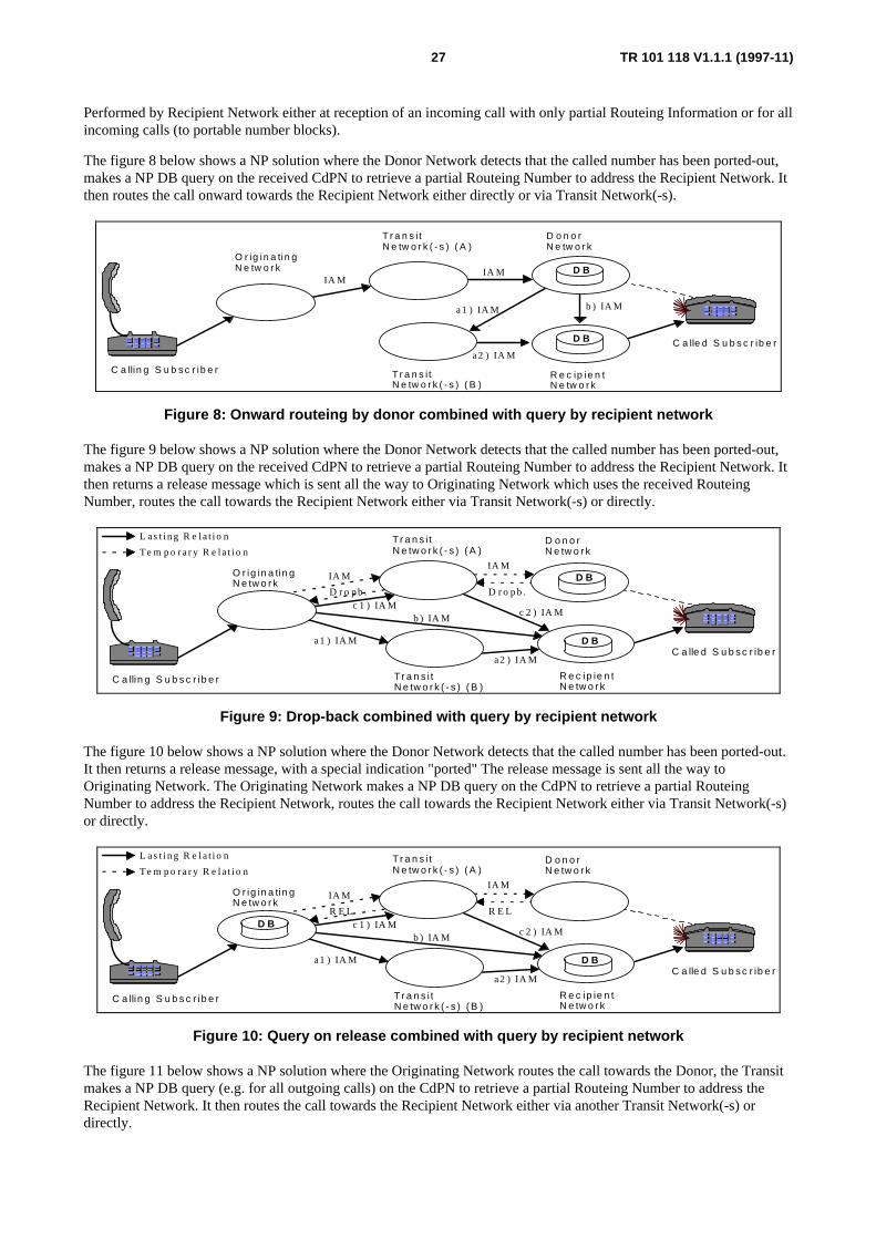
TR 101 118 V1.1.1 (1997-11)27
Performed by Recipient Network either at reception of an incoming call with only partial Routeing Information or for allincoming calls (to portable number blocks).
The figure 8 below shows a NP solution where the Donor Network detects that the called number has been ported-out,makes a NP DB query on the received CdPN to retrieve a partial Routeing Number to address the Recipient Network. Itthen routes the call onward towards the Recipient Network either directly or via Transit Network(-s).
IA M
a1 ) IA M
a2 ) IA M
b ) IA M
IA M
O r ig in a tin gN e tw o r k
C a llin g S u b s c r ib e r
D o n o rN e tw o r k
R e c ip ie n tN e tw o r k
C a lle d S u b s c r ib e r
T r a n s i tN e tw o r k ( - s ) ( B )
D B
Tr a n s i tN e tw o r k ( - s ) ( A )
D B
Figure 8: Onward routeing by donor combined with query by recipient network
The figure 9 below shows a NP solution where the Donor Network detects that the called number has been ported-out,makes a NP DB query on the received CdPN to retrieve a partial Routeing Number to address the Recipient Network. Itthen returns a release message which is sent all the way to Originating Network which uses the received RouteingNumber, routes the call towards the Recipient Network either via Transit Network(-s) or directly.
IA M
D r o p b . D r o p b .
IA MO r ig in a tin gN e tw o r k
C a llin g S u b s c r ib e r
D o n o rN e tw o r k
C a lle d S u b s c r ib e r
Tr a n s i tN e tw o r k ( - s ) ( A )
b ) IA M
a1 ) IA M
a2 ) IA M
Tr a n s i tN e tw o r k ( - s ) ( B )
L as t i n g R e la t i o n
Te m p o r a r y R e la t i o n
R e c ip ie n tN e tw o r k
c 1 ) IA M c 2 ) IA M
D B
D B
Figure 9: Drop-back combined with query by recipient network
The figure 10 below shows a NP solution where the Donor Network detects that the called number has been ported-out.It then returns a release message, with a special indication "ported" The release message is sent all the way toOriginating Network. The Originating Network makes a NP DB query on the CdPN to retrieve a partial RouteingNumber to address the Recipient Network, routes the call towards the Recipient Network either via Transit Network(-s)or directly.
IA M
R E L R E L
IA MO r ig in a tin gN e tw o r k
C a llin g S u b s c r ib e r
D o n o rN e tw o r k
C a lle d S u b s c r ib e r
Tr a n s i tN e tw o r k ( - s ) ( A )
b ) IA M
a1 ) IA M
a2 ) IA M
Tr a n s i tN e tw o r k ( - s ) ( B )
L as t i n g R e la t i o n
Te m p o r a r y R e la t i o n
R e c ip ie n tN e tw o r k
c 1 ) IA M c 2 ) IA M
D B
D B
Figure 10: Query on release combined with query by recipient network
The figure 11 below shows a NP solution where the Originating Network routes the call towards the Donor, the Transitmakes a NP DB query (e.g. for all outgoing calls) on the CdPN to retrieve a partial Routeing Number to address theRecipient Network. It then routes the call towards the Recipient Network either via another Transit Network(-s) ordirectly.

TR 101 118 V1.1.1 (1997-11)28
IA M
a1 ) IA M
a2 ) IA M
b ) IA M
C a llin g S u b s c r ib e r
D o n o rN e tw o r k
R e c ip ie n tN e tw o r k
C a lle d S u b s c r ib e r
Tr a n s i tN e tw o r k ( A )
D B
Tr a n s i tN e tw o r k ( - s ) ( B )
O r ig in a tin gN e tw o r k
D B
Figure 11: "All call query" by transit network combined with query by recipient network
The figure 12 below shows a NP solution where the Originating Network makes a DB query on the CdPN to retrieve apartial Routeing Number to address the Recipient Network, routes the call towards the Recipient Network either viaTransit Network(-s) or directly (option b).
b) IAM
a1 ) IAM
a2 ) IAM
Orig inatingNetwork
D onorNetwork
Rec ip ientNetwork
C alled S ubsc r iber
TransitNetwork(-s)
D B
C alling S ubsc r iber
D B
Figure 12: "All call query" by originating network combined with query by recipient network.
For the figures 8-12, the recipient network either traps all incoming calls or traps calls received with a special indication"ported call" or with a partial Routeing number. It then makes a query to "own" NP DB to obtain a complete Routeingnumber to address the recipient exchange.
In all the above solutions the NP DB outside the Recipient network contains Routeing Information to address therecipient Network only. This principle has two main advantages:
a it allows for privacy of the recipient network;
b) less DB updates are needed, since other Network Data Bases need not be updated e.g. when the recipientNetwork operator performs internal restructuring of its Network.
For all solutions, the Routeing number is enclosed in the forward message to avoid NP DB query in Transit Network(-s)and to enable trapping of NP DB mismatch by Recipient Network.
6.6.2 Interaction with supplementary services
Interactions with supplementary services are depending on the first Routeing step and are described in previoussubclauses.
6.6.3 Interaction with IN based services
No interference/impact identified.
6.6.4 Interaction with carrier selection
Interactions with carrier selection is depending on the first Routeing step and are described in previous subclauses.
TR 101 118 V1.1.1 (1997-11)29
6.6.5 Interaction with statistical counters
Interactions with statistical counters is depending on the first Routeing step and are described in previous subclauses.
6.6.6 Required forward information transfer between networks
Forward Routeing information need to be sent over Network borders.
6.6.7 Required backward information transfer between networks
NP related backward information is depending on the first Routeing step and are described in previous subclauses.
6.6.8 NP routeing loop detection issues
Some loop cases are identified, since this solution involves retrieval of Routeing information two times, for a call overNetwork borders. Only one retrieval required if Originating and Recipient Networks are the same.
Loop and NP DB mismatch detection can easily be performed by recipient network by comparing received RouteingNumber (indicating recipient Network ID i.e. own network) with the Routeing Number received from the own NP DB.I.e. the retrieved Routeing number should not indicate other network than own.
6.6.9 Pros
The main advantages with this solution are that:
a) network operators need not inform others when making changes in their internal network, i.e. privacy of networkinternals is maintained;
b) less NP DB updates are needed.
In addition to the above listed pros, please see relevant subclauses for each of the first step Routeing options.
6.6.10 Cons
The main disadvantages with this solution are that:
a) additional processing capacity (the query) is needed for all incoming calls to Recipient network.
In addition to the above listed cons, please see relevant subclauses for each of the first step Routeing options.
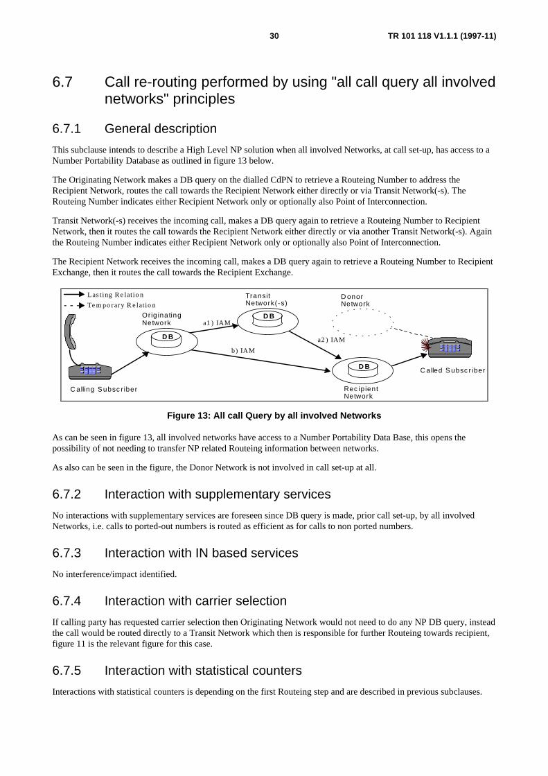
TR 101 118 V1.1.1 (1997-11)30
6.7 Call re-routing performed by using "all call query all involvednetworks" principles
6.7.1 General description
This subclause intends to describe a High Level NP solution when all involved Networks, at call set-up, has access to aNumber Portability Database as outlined in figure 13 below.
The Originating Network makes a DB query on the dialled CdPN to retrieve a Routeing Number to address theRecipient Network, routes the call towards the Recipient Network either directly or via Transit Network(-s). TheRouteing Number indicates either Recipient Network only or optionally also Point of Interconnection.
Transit Network(-s) receives the incoming call, makes a DB query again to retrieve a Routeing Number to RecipientNetwork, then it routes the call towards the Recipient Network either directly or via another Transit Network(-s). Againthe Routeing Number indicates either Recipient Network only or optionally also Point of Interconnection.
The Recipient Network receives the incoming call, makes a DB query again to retrieve a Routeing Number to RecipientExchange, then it routes the call towards the Recipient Exchange.
b) IAM
a1 ) IAM
a2 ) IAM
Orig inatingNetwork
D onorNetwork
Rec ip ientNetwork
C alled S ubsc r iber
TransitNetwork(-s)
D B
Las t ing R e lat io n
Te m po rary R e lat io n
C alling S ubsc r iber
D B
D B
Figure 13: All call Query by all involved Networks
As can be seen in figure 13, all involved networks have access to a Number Portability Data Base, this opens thepossibility of not needing to transfer NP related Routeing information between networks.
As also can be seen in the figure, the Donor Network is not involved in call set-up at all.
6.7.2 Interaction with supplementary services
No interactions with supplementary services are foreseen since DB query is made, prior call set-up, by all involvedNetworks, i.e. calls to ported-out numbers is routed as efficient as for calls to non ported numbers.
6.7.3 Interaction with IN based services
No interference/impact identified.
6.7.4 Interaction with carrier selection
If calling party has requested carrier selection then Originating Network would not need to do any NP DB query, insteadthe call would be routed directly to a Transit Network which then is responsible for further Routeing towards recipient,figure 11 is the relevant figure for this case.
6.7.5 Interaction with statistical counters
Interactions with statistical counters is depending on the first Routeing step and are described in previous subclauses.

TR 101 118 V1.1.1 (1997-11)31
6.7.6 Required forward information transfer between networks
Routeing information need not, but might optionally, be sent over Network borders.
6.7.7 Required backward information transfer between networks
No new NP related information is identified in the backward direction for call Routeing purposes.
6.7.8 NP routeing loop detection issues
Some loop cases are identified, since this solution involves retrieval of Routeing information several times, for a callover Network borders. Only one retrieval is required if Originating and Recipient Networks are the same.
6.7.9 Pros
The main advantages with this solution are that:
a) it allows the Donor Network to discontinue maintaining data for subscriber numbers no longer inresponse of;
b) as efficient utilization of Network resources, as for calls to non ported numbers;
c) all supplementary services will work, as for calls to non ported numbers, thanks to no dependency on othernetworks (than used for other calls) to set up the call to recipient;
d) originating Network has full control over call Routeing;
f) statistical circuit quality counters will work as today thanks no release involved prior redirection;
e) donor Network will not need to consider processing capacity for incoming calls to ported-out numbers;
f) equal treatment of calls to both ported and not ported subscribers;
g) calls to really vacant subscribers are trapped already in Originating, this saving load (in both Transit and Donor)and possible accounting costs (in Originating) for non successful calls;
j) no interference with Carrier Selection;
j) robust network since no dependency on other networks in getting Routeing information for calls to ported-outnumbers;
k) network operators need not inform others when making changes in their internal network, i.e. privacy of networkinternals is maintained;
l) not mandatory to introduce Routeing Number transfer between networks;
o) Routeing can be based on Routeing number only, i.e. current Routeing scheme can be removed;
p) routeing number allocation can be network internal business if RN is not sent between networks.
6.7.10 Cons
The main disadvantages with this solution are that:
a) might be longer call set-up time for calls to not ported subscribers, than in the onward Routeing, Query onRelease and Drop-back cases;
b) additional processing capacity (the query) is needed for all calls in all involved networks;
c) large processing capacity required in DB since all calls will require DB query;
d) all networks required to invest in DB techniques.

TR 101 118 V1.1.1 (1997-11)32
7 Examples of locations of number portability database(-s) within networks
7.1 General descriptionDepending on the evolutionary level in a particular Network the NP data base will be located in different places of theNetwork or possibly even external to the Network, the following principles of NP data storing have been identified,described and evaluated:
a) exchange based (distributed) solutions;
b) exchange external (centralized) solutions.
The following options for NP data query places have been identified, described and evaluated:
1) originating Local Exchange;
2) gateway Exchange(-s);
3) transit or Gateway Exchange(-s);
4) donor Local Exchange(-s).
All combinations of the above could exist, as described in the following subclauses.
Regardless of data storing place, the Exchange/Network can act according to different NP principles, e.g. OnwardRouteing the call, Dropping back the Re-routing information or even acting as a database and responding a query withRe-routing information.
The emphasis in this subclause is on network internal options which not are subjects for standardization but desiredoptions need still to be described to support the development of NP standards allowing multivendor solutions.
NOTE 1: Despite figures show Local, Transit or Gateway Exchanges it should be understood that it is thefunctionality of these Exchanges that is intended, i.e. it shall be assumed that the functionality of Local,Transit and Gateway Exchanges can reside in the same physical Network Element. Incoming calls fromother networks might very well be received directly to Transit or even Local Exchanges if this has beenagreed on by bilateral agreements.
NOTE 2: The emphasis on the location of exchange external DB is from where the DB access is performed andwhat triggered the DB access. Despite the figures show the location of the DB within the domain of aparticular Network it shall be understood that the DB might very well be located outside that domain, e.g.commonly maintained by a third party.

TR 101 118 V1.1.1 (1997-11)33
7.2 Network overview for geographic numbersThe figure 14 below shows an overview of an evolved Network supporting NP.
LE
TE
GW
GWMSC
NP DB
MSC-VLR
NP DB
NP DB
TE
LE
GW
GW
Netw 1 Netw 2
Netw 3
Portabilitydomain
NonPortabilitydomain
NP DB = Number Portability Data Base.
TransportNetwork
Figure 14: Network overview for number portability.
One should understand that it is up to each of the Network providers if the NP DB is located in a separate NetworkElement or replicated (i.e. NP DB in LE, TE or GW) in each of the nodes, e.g. this collocation might be the case forsmall Network providers.
The inclusion of Network 3 in the figure should be understood in such a way that despite the Network is not being partof the portability domain it could still maintain an own number portability database this to allow cost effective Routeingto right Network for its outgoing calls. It shall however be understand that Network 3 might or might not be part of another portability domain than the one shared between Networks 1 and 2.
The inclusion of the Non portability domain should be understood in such a way that calls originated from this Networkis allowed to be routed to the Networks 1 or 2 depending on the historical number series allocation, i.e. to DonorNetwork. The gateway in the call receiving Network will then trap this call and make a database query to retrieveRouteing information.
Despite not shown, one should keep in mind that the principals outlined in the figure 14 above will exist once perportability domain, i.e. the GW might be differing depending on geographic area, the service level of called subscribersetc.

TR 101 118 V1.1.1 (1997-11)34
7.3 NP re-routing data stored in donor network
7.3.1 NP re-routing data stored in donor local exchange
7.3.1.1 General description
The principle to store the Number Portability information in the Donor Local Exchange, as outlined in figure 15 below,is often the first solution proposed since at low portability level, no extra Network elements are needed to support NP. Inthis solution calls to ported-out numbers should first be routed to the Donor Local Exchange before the RouteingInformation can be obtained.
D o n o r N e tw o rk
P o r te d a w a yS u b s c r ib e r
D a ta B a s e s o lu t io n s in
D B
L E
T E
G W
Figure 15: NP data stored in the donor local exchange
This DB location might be used for many of the high level solutions, e.g.:
a) incoming Call to ported-out subscriber is Onward Routed by Donor LE;
b) incoming Call to ported-out subscriber is Dropped-back to TE or GW, with Re-routing information.
Please note that the Drop-back might be restricted to the domain of the Donor Network, i.e. in that case the DonorNetwork would still, in a high level architecture, act as an Onward Routeing Network.
7.3.1.2 Interaction with supplementary services
The service level is dependent on Donor LE, there will be interaction, i.e. the call will fail, with essential services if theconnection to the Donor exchange is of lower functionality level than the incoming interconnection used to the GW/TE.No additional interworking is foreseen for non essential services.
7.3.2 NP re-routing data stored in donor network transit exchanges
7.3.2.1 General description
The principle to store the Number Portability information in the Donor Transit Exchange(-s), as outlined in figure 16, is apossible enhancement compared storing data in Donor LE since calls to ported-out numbers do not necessarily need toreach the Donor local exchange before the Routeing Information can be obtained, i.e. if these calls are trapped in the transitlevel of Donor Network and then after retrieval of Routeing information routed to the correct Recipient Network/Exchangeeither by onward Routeing or Drop-back (to GW) principles. Still no extra Network element(-s) are needed to support NP.

TR 101 118 V1.1.1 (1997-11)35
L E
L E
L E
D B
G W
P o rte d in /o u tS u b s c r ib e r(-s )
D a ta B a s e s o lu t io n s in
T E
D o n o r N e tw o rk
Figure 16: NP data stored in the donor transit exchange(-s)
An alternative to trapping the calls to ported-out numbers in TE is trapping these calls by Donor LE and then releasethem to TE according to QoR principles, i.e. TE only retrieves data after receiving a release indicating "ported".
This DB location might be used for many high level NP solutions, e.g.:
a) calls to ported-out subscribers are trapped and onward routed by Donor TE;
b) call Drop-back to GW, with Re-routing information, from TE;
c) query on Release (QoR), from LE.
The incoming calls are routed to the Transit Exchange(-s), so that the DB can be queried and call be re-routed to correctdestination.
The Originating calls to ported-out numbers are e.g. handled in the following way:
1) first a check is made if called subscriber is defined/connected in own LE;
2) a) if so, the call is connected according to existing procedures;
b) if not, the call is redirected to transit exchange.
optionally with a special indication (e.g. a prefix) to simplify next step;
3) the transit exchange traps the call and makes the DB query;
4) the call is re-routed to correct destination.
At least two options exist to indicate that the subscriber has been ported out:
i) the ported-out number is marked as "ported" and only calls to "ported" subscribers are routed to TE;
ii) the ported-out number is marked as "vacant" and all calls to "vacant" subscribers are routed to TE, used if nodata about ported-out numbers are stored in Donor LE.
A not so efficient option is to always route the Originating calls to transit Network and then trombone or drop them backto the LE, i.e. no try is made to connect the call locally first.
The procedures in the Originating LE discussed here are of course valid/defined per number block, i.e. the procedure isnot needed in number blocks not opened for portability.
7.3.2.2 Interaction with supplementary services
The service level is no longer dependent on Donor Local Exchange.
7.3.3 NP re-routing data stored in donor network GW exchanges
Number portability data could theoretically be stored internally in Donor Network GW exchange(-s), but this isprobably not yet a feasible/desirable solution due to amount of required data.

TR 101 118 V1.1.1 (1997-11)36
7.3.4 Re-routing data stored exchange external in donor network
7.3.4.1 General description
A further evolution of NP data management is that the data is stored centrally, i.e. Exchange external, this to simplifymanagement.
The following different origination's of NP database queries have been identified:
a) query by the Donor Local Exchange;
b) query by transit exchange next to the Donor Local exchange;
c) query by gateway exchange(-s).
More than one principle can be applied in a certain Network at the same time, depending on evolution of theNetwork/exchange in question.
Please note that the "central database" can actually be several databases according to replicated or load sharing methodsor both, e.g. two databases (mated pair) could serve a number of number series and two other DBs could serve othernumber series.
7.3.4.2 Query to central database by donor local exchange
7.3.4.2.1 General description
The principle of performing a DB query, as outlined in figure 17, in the Donor LE has advantages, compared to LocalExchange internal stored data, mainly with respect to simplified data management and also that it can easily be scaled upto other query methods (e.g. by Transit or Gateway exchanges).
D o n o r N e tw o rk
P o r te d in /o u tS u b s c r ib e r( -s )
D a ta B a s e s o lu t io n s in
L E
T E D B
G WL E
L E
Figure 17: NP data stored exchange external and queried by donor local exchange(-s)
The same NP functions, as for Exchange internal data, are supported by this solution.
7.3.4.2.2 Interaction with supplementary services
Same as for Donor LE Exchange Internal NP DB.
7.3.4.3 Query to central database by donor transit exchange(-s)
7.3.4.3.1 General description
The principle of performing a DB query, as outlined in figure 18, in Donor TE, has advantages, compared to Query byDonor Local Exchange, mainly because it results in that calls to ported out subscribers do not reach the Donor localexchange, i.e. these calls are trapped in the transit level of Donor Network and then routed to the correct RecipientNetwork/Exchange.
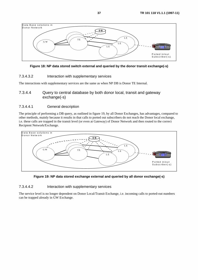
TR 101 118 V1.1.1 (1997-11)37
D o n o r N e tw o rk
P o rte d in /o u tS u b s c r ib e r (-s )
D a ta B a s e s o lu t io n s in
L E
D B
G WL E
L E
T E
Figure 18: NP data stored switch external and queried by the donor transit exchange(-s)
7.3.4.3.2 Interaction with supplementary services
The interactions with supplementary services are the same as when NP DB is Donor TE Internal.
7.3.4.4 Query to central database by both donor local, transit and gatewayexchange(-s)
7.3.4.4.1 General description
The principle of performing a DB query, as outlined in figure 19, by all Donor Exchanges, has advantages, compared toother methods, mainly because it results in that calls to ported out subscribers do not reach the Donor local exchange,i.e. these calls are trapped in the transit level (or even at Gateway) of Donor Network and then routed to the correctRecipient Network/Exchange.
D o n o r N e tw o rk
P o rte d in /o u tS u b s c r ib e r(-s )
D a ta B a s e s o lu t io n s in
L E
G WL E
L E
T E
D B
Figure 19: NP data stored exchange external and queried by all donor exchange(-s)
7.3.4.4.2 Interaction with supplementary services
The service level is no longer dependent on Donor Local/Transit Exchange, i.e. incoming calls to ported-out numberscan be trapped already in GW Exchange.

TR 101 118 V1.1.1 (1997-11)38
7.4 NP re-routing data stored/ accessed in transit network
7.4.1 NP re-routing data stored/accessed in transit network gatewayexchange(-s)
Number portability data could theoretically be stored Exchange internal in a Transit Network, but this is probably notyet a feasible/desirable solution nor is advantages with this identified.
7.4.2 NP re-routing data stored/accessed centrally and accessed bytransit network
7.4.2.1 General description
A further evolution of NP data management is that the data is not only stored/available in the Donor Network, insteadalso stored in e.g. Transit Networks, as outlined in figure 20, or stored centrally commonly accessible by all involvedNetworks. Examples for management of NP data to several networks can be found in other subclauses.
The main advantage here is a more efficient Routeing of calls and that call set-up no longer is depending on DonorNetwork only.
T r a n s i t N e tw o r k ( -s )D a ta B a s e s o lu t io n s in
D B
G W (1 ) G W (n )
Figure 20: NP data stored exchange external and queried by transit network exchange(-s)
This location of NP DB can be used for several of the high level solutions, e.g.:
a) always query method,
the Transit Network GW (or optionally also a TE) receives an incoming call traps the call being destined to anumber series that is opened for NP makes a NP DB query to obtain a RN towards Recipient Network. Finally itroutes the call with the use of RN;
b) Query on Release (QoR), the Transit Network GW (or optionally also a TE) receives a Release messageindicating that the called number has been ported-out, makes a NP DB query to obtain a RN towards RecipientNetwork. Finally it routes the call with the use of RN.
An option to the above is that instead of using the RN to route the call onward towards recipient, the Transit networkcan return the RN to the previous network according to Drop-back principles. Drop-back could also be used withinTransit Network in case QoR is performed in e.g. GW(n) and call is dropped back to GW(1).
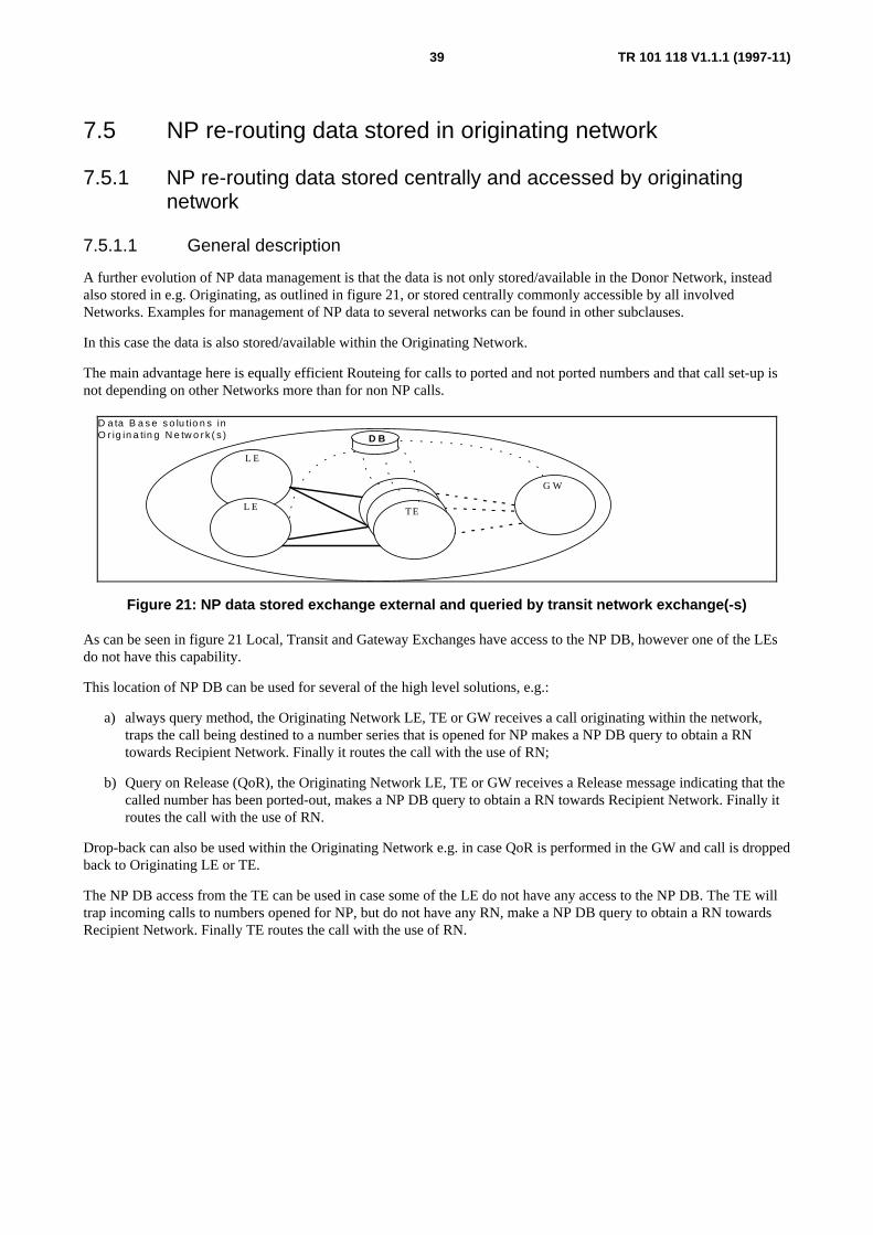
TR 101 118 V1.1.1 (1997-11)39
7.5 NP re-routing data stored in originating network
7.5.1 NP re-routing data stored centrally and accessed by originatingnetwork
7.5.1.1 General description
A further evolution of NP data management is that the data is not only stored/available in the Donor Network, insteadalso stored in e.g. Originating, as outlined in figure 21, or stored centrally commonly accessible by all involvedNetworks. Examples for management of NP data to several networks can be found in other subclauses.
In this case the data is also stored/available within the Originating Network.
The main advantage here is equally efficient Routeing for calls to ported and not ported numbers and that call set-up isnot depending on other Networks more than for non NP calls.
O r ig in a tin g N e tw o r k ( s )D a ta B a s e s o lu tio n s in
L E
L E TE
D B
G W
Figure 21: NP data stored exchange external and queried by transit network exchange(-s)
As can be seen in figure 21 Local, Transit and Gateway Exchanges have access to the NP DB, however one of the LEsdo not have this capability.
This location of NP DB can be used for several of the high level solutions, e.g.:
a) always query method, the Originating Network LE, TE or GW receives a call originating within the network,traps the call being destined to a number series that is opened for NP makes a NP DB query to obtain a RNtowards Recipient Network. Finally it routes the call with the use of RN;
b) Query on Release (QoR), the Originating Network LE, TE or GW receives a Release message indicating that thecalled number has been ported-out, makes a NP DB query to obtain a RN towards Recipient Network. Finally itroutes the call with the use of RN.
Drop-back can also be used within the Originating Network e.g. in case QoR is performed in the GW and call is droppedback to Originating LE or TE.
The NP DB access from the TE can be used in case some of the LE do not have any access to the NP DB. The TE willtrap incoming calls to numbers opened for NP, but do not have any RN, make a NP DB query to obtain a RN towardsRecipient Network. Finally TE routes the call with the use of RN.

TR 101 118 V1.1.1 (1997-11)40
7.6 NP re-routing data stored in recipient networkThe Recipient Network might need to access NP DB for several reasons:
a) receiving an incoming call to a ported-in number, without any RN or with incomplete RN, to obtain complete RNto Recipient Exchange,
b) in a "Query on Release" case for an originating call to a ported-in number,: this case is covered as an originatingcase.
c) in a "all call query" case for an originating call to a ported-in number. This case is covered as an originating case.
NP DB access in a Recipient Network (when acting as such) is only of interest in either GW Exchanges or TE sincethere is no need to access it if already in Recipient LE, see figure 22.
The main reason for accessing "own" NP DB for an incoming call to a ported-in number is not to expose networkinternal structure to other network operators, i.e. have privacy.
R e c ip ie n t N e tw o r k
P o r te d inS u b s c r ib e r ( -s )
D a ta B a s e s o lu t io n s in
L E
G WL E
L E
T E
D B
Figure 22: NP data stored exchange external and queried by recipient GW or TE

TR 101 118 V1.1.1 (1997-11)41
8 High level evolutionary model for np and sccp usingservices to geographic numbers
8.1 Background informationSome services (e.g. CCBS, CCNR) make use of non-circuit related signalling. Within ITU-T Signalling System No.7,non-circuit related signalling is supported almost exclusively by the SCCP layer.
SCCP allows messages to be addressed with Global Titles (GT), which may contain ITU-T Recommendation E.164 [1]numbers, including ITU-T Recommendation E.164 [1] numbers which are subject to portability. Where a called GT inan SCCP message contains a ported number the SCCP message should be delivered to the recipient network, and to theappropriate node within the recipient network.
Traditionally, SCCP GT Translation (GTT) functions and data have been implemented as distinct from the call controlrouteing functions and data, and have also typically only required to a few hundred entries.
With the advent of services which use ITU-T Recommendation E.164 [1] numbers as GTs, and particularly with theintroduction of number portability, such GTT capability is insufficient. Hence solutions should be found which allow thecorrect delivery of SCCP messages addressed with ITU-T Recommendation E.164 [1] numbers, including portednumbers.
An example to highlight the problem, the CCBS/CCNR (as standardized by ETSI), uses the called party number(CdPN), as dialled by user, as Global Title, then SCCP will, in the Global Title Analysis (GTA) route the message, tothe destination exchange, according to which number block the dialled number is part of. This e.g. means that the 4 lastdigits of the CdPN need not be analysed to determine destination Network and Exchange neither need data exist for the4 last digits in the GTA, i.e. this reduces the amount of data in GTA by 10.000 (if called party number is part of a10.000 number block).
The use of Called Party Number (CdPN), as entered by the calling subscriber, as Global Title, might no longer lead tothe right local exchange since a particular dialled subscriber number, part of a certain 10.000 number block, might berelocated/ported to another operators Exchange.
One should not forget the impact on CCBS/CCNR requests initiated from an ISDN PBX (ISPBX), in this case theCCBS request is, from the Local Exchange point of view, handled transparently without any relation to the previouslybusy/no response call, i.e. either the Local Exchange or SS no. 7 network should be able to (re-)route these SCCPmessages to the right destination Local Exchange with some new functionality.
8.2 Requirements on solutions for routeing of SCCP messagesThe routeing of SCCP messages should be achieved by the SCCP, and data available to the SCCP, without reference tothe application part providing the service. This is required because an end to end service supported by originating andterminating networks should be available even if the service application is not supported by the donor or transitnetworks.
The integrity of services provided by the SCCP layer should be maintained also in a NP environment. The main servicesprovided by the SCCP are:
a) connectionless message service with sequencing not guaranteed;
b) connectionless message service with sequencing guaranteed;
c) notification of failure to deliver a connectionless message;
d) basic connection oriented service;
e) connection oriented service with flow control.
NOTE: Currently defined inter-operator non-circuit related services utilize only connectionless service.

TR 101 118 V1.1.1 (1997-11)42
Solutions should be easy to maintain and keep consistent with chosen solutions for calls to ported numbers. Themaintenance of large GTT tables is a new function for most Network Operators, and solutions should aim to minimizethe effort required for this activity. Inconsistency between GTT data and call routeing data could lead to incompleteservice being offered to customers with ported numbers or customers calling these numbers.
Inconsistency between the GTT data held by different Network Operators may lead to circular routeing of messages.
8.3 Proposal for solutionsIn all architectures identified for circuit related signalling, there exists one or more databases which assist the routeing ofcalls to a ported number. These Number Portability databases may be internal to an exchange (for example, in the donorexchange) or may be external to any exchange.
It is proposed to allow using these databases also to assist the routeing of SCCP messages. The database would bequeried during execution of the GTT function for ITU-T Recommendation E.164 [1] numbers. The result of the querywould be a modified GT which will be reanalysed within the SCCP to determine how to subsequently route the message.
8.4 General introduction to described modelsThe following subclauses describes a number of possible high level solutions to support supplementary services (e.g.CCBS, CCNR, etc.) using Global Title based Routeing in a NP environment.
Three main approaches are identified, i.e. that a Routeing Global Title (RGT) is retrieved and used:
a) by Donor Network that reroute the TCAP/SCCP message to correct destination;
b) by Originating LE;
c) by a SCCP Transit node, e.g. a SPR.
This case can also be evolved to use same NP DB (and data) as used for Routeing of calls.
For all solutions several techniques could be used.

TR 101 118 V1.1.1 (1997-11)43
8.4.1 SCCP routeing solutions in donor network/exchange
8.4.1.1 General description
In this NP solution for Routeing of TCAP/SCCP messages to the Recipient Exchange, the Donor Network/Exchangemaintains all the data, e.g. a Routeing Global Title (RGT), for ported-out numbers. The NP DB is located eitherexchange internal or external of the LE.
As outlined in figure 23, the Originating Network/Exchange routes the TCAP/SCCP message according to the historicallocation of the Number Series that the called party Directory Number is part of.
C a llin g S u b s c r ib e r
D o n o rN e tw o r k
R e c ip ie n tN e tw o r k
P o r te dS u b s c r ib e r
D BO r ig in a tin gN e tw o r k
L a s t i n g R e l a t i o n
T e m p o r a r y R e l a t i o n
S S N o . 7 L E L E
L E
Figure 23: DB query and TCAP/SCCP message redirection performed by donor LE
The Donor Network (e.g. Local Exchange) detects that the called number has been ported-out, makes a DB query toretrieve a Routeing Global Title and replaces the received GT with this. Thereafter the TCAP/SCCP message is Onwardrouted towards the Recipient Exchange.
The Recipient Network need not make an own DB query since call is routed directly to Recipient Exchange.
This solution for Routeing of connection less services can be compared with the "onward Routeing" solution forordinary call set-up as outlined in subclause 6.2.1.
8.4.1.2 Pros
The main advantages with this solution are that:
a) only the Donor Network/Exchange needs to maintain NP data for ported-out numbers;
b) no impact when addressing not ported subscribers.
8.4.1.3 Cons
The main disadvantages with this solution are that:
a) the recipient network(-s) should inform donor networks when modifying network internal structure, i.e. it doesnot allow for privacy for Network Operators;
b) impacts TCAP and SCCP layer if not two transaction ID are consumed per CCBS request.
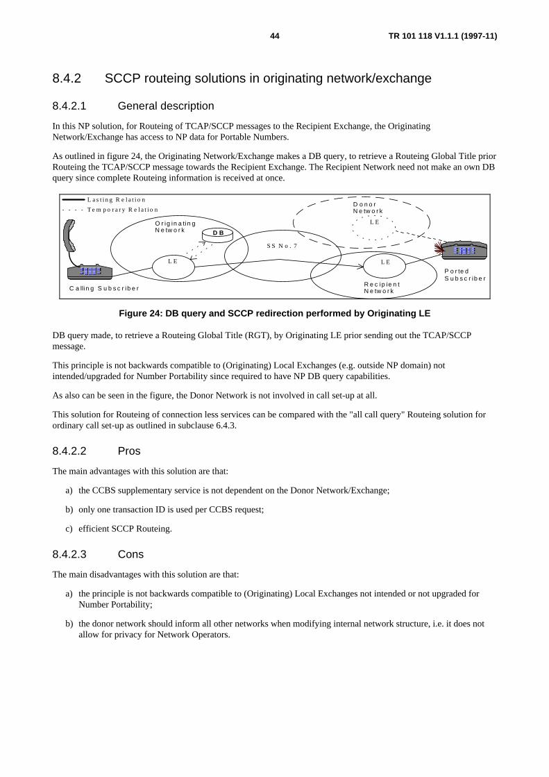
TR 101 118 V1.1.1 (1997-11)44
8.4.2 SCCP routeing solutions in originating network/exchange
8.4.2.1 General description
In this NP solution, for Routeing of TCAP/SCCP messages to the Recipient Exchange, the OriginatingNetwork/Exchange has access to NP data for Portable Numbers.
As outlined in figure 24, the Originating Network/Exchange makes a DB query, to retrieve a Routeing Global Title priorRouteing the TCAP/SCCP message towards the Recipient Exchange. The Recipient Network need not make an own DBquery since complete Routeing information is received at once.
C a llin g S u b s c r ib e r
D o n o rN e tw o r k
R e c ip ie n tN e tw o r k
P o r te dS u b s c r ib e r
O r ig in a tin gN e tw o r k
L a s t i n g R e l a t i o n
T e m p o r a r y R e l a t i o n
S S N o . 7
L E L E
L E
D B
Figure 24: DB query and SCCP redirection performed by Originating LE
DB query made, to retrieve a Routeing Global Title (RGT), by Originating LE prior sending out the TCAP/SCCPmessage.
This principle is not backwards compatible to (Originating) Local Exchanges (e.g. outside NP domain) notintended/upgraded for Number Portability since required to have NP DB query capabilities.
As also can be seen in the figure, the Donor Network is not involved in call set-up at all.
This solution for Routeing of connection less services can be compared with the "all call query" Routeing solution forordinary call set-up as outlined in subclause 6.4.3.
8.4.2.2 Pros
The main advantages with this solution are that:
a) the CCBS supplementary service is not dependent on the Donor Network/Exchange;
b) only one transaction ID is used per CCBS request;
c) efficient SCCP Routeing.
8.4.2.3 Cons
The main disadvantages with this solution are that:
a) the principle is not backwards compatible to (Originating) Local Exchanges not intended or not upgraded forNumber Portability;
b) the donor network should inform all other networks when modifying internal network structure, i.e. it does notallow for privacy for Network Operators.

TR 101 118 V1.1.1 (1997-11)45
8.4.3 SCCP routeing solutions in originating and recipientnetwork/exchange
8.4.3.1 General description
In the solution outlined in figure 25, the NP DB query is made firstly at Signalling Gateway (SPR) level of OriginatingNetwork, i.e. the SCCP level traps, by analysing the received Global Title, TCAP/SCCP messages directed towardsnumber series that are allowed for Number Portability makes a DB query, alternative a, to obtain a Routeing GlobalTitle to Recipient Network, modifies the Global Title and routes the message onward to Recipient Network.
The SPR of the Recipient Network traps the incoming TCAP message and makes a new DB query, alternative c, toobtain the Routeing GT of recipient Exchange) and routes the TCAP/SCCP message onward to Recipient Exchange.
S S N o . 7
S P R S P R
C a llin g S u b s c r ib e r
D o n o rN e tw o r k
R e c ip ie n tN e tw o r k
P o r te dS u b s c r ib e r
O r ig in a tin gN e tw o r k
L a s t i n g R e la t i o n
T e m p o r a r y R e l a t i o n
D B
L E L E
L E
D B
a b
c
S P R : S i g n a l l i n g P o in t w i t h R e l a y f u n c t i o n s
Figure 25: DB query and SCCP redirection performed at STP level
The solution above also allows for cases where some Local Exchange, see alternative b in figure 25, perform the NP DBquery according to figure 24 but other LEs leaves this task to the Originating (or even a Transit) SPR of the SS no.7network.
As also can be seen in the figure, the Donor Network is not involved in call set-up at all.
The DB could very well coexist in every (or some of) the SPR, i.e. the NP data being replicated into the GTT for loadsharing reasons.
A variant of this solution is that the NP DB triggering point, i.e. the SPR, could also be enhanced to be collocated with aSSP/Service Control Point (SCP) or Service Switching and Control Point (SSCP), i.e. allowing IN techniques to be usedto obtain the Routeing Global Title This would also allow the use of same NP DB for both call and connection lessservice Routeing, retrieving the same or differing Routeing information.
This solution for Routeing of connection less services can be compared with the two step "all call query" Routeingsolution for ordinary call set-up as outlined in subclause 6.6.1 and figure 12.
8.4.3.2 Pros
The main advantages with this solution are that:
a) network operators need not inform others when main changes in their internal network, i.e. privacy of networkinternals is maintained;
b) thanks to "a" less administrative procedures between Networks.
8.4.3.3 Cons
The main advantages with this solution are that:
a) several (at least two) DB queries are needed per TCAP/SCCP message to portable numbers, i.e. regardlessnumber is ported-out or not (only one query needed if the called number is served by the Originating Network).

TR 101 118 V1.1.1 (1997-11)46
9 Proposed generic distributed functional entity modelfor number portability
9.1 General informationA functional structure is needed to ease allocation of the different NP related tasks required, the figure 26 below is aproposal of a generic Distributed Functional Entity Model for Number Portability. This subclause addresses onlyRouteing related aspects. The figure also depicts the functional entities and their relationship.
CCF
CCPF NPCF
M-NPMF
NPMF1
Network (1) Network (n)
NPMFn
CCF Call Control Functions CCPF Call Control Portability FunctionsNPCF NP Control Functions NPDF NP Data FunctionsNPMF NP Management Functions M-NPMF Master NPMF
Real timefunctionalentities
NonReal timefunctionalentities
NPDF
Figure 26: Functional entity model for number portability
The definition of the functional entities (CCF, Call Control Portability Functions (CCPF), Number Portability ControlFunctions (NPCF), Number Portability Data Functions (NPDF), Number Portability Management Functions (NPMF)and M-NPMF), with respect to Service Provider Portability (NP) for both Geographic (GNP) and Non GeographicNumber Portability (NGNP) is found in the following subclauses.
Both Routeing and NP data management aspects of each functional entity is addressed, however no attempt is made tolimit an individual Network Operators implementation of the functionality associated with each of the functional entities.
In the scenario of e.g. an exchange internal "onward Routeing" solution by Donor LE:
a) the CCF would have a trigger, e.g. a line category, on the ported-out number which would cause the CCPFinteracting with NPCF;
b) the NPCF would then interact with the NPDF to obtain the Routeing Information and then instruct the CCPF tointroduce it into CCF Routeing data;
c) the task of NPMF is then to:
1) load the translation table in NPDF;
2) set the triggering condition in CCF/CCPF;
3) maintain the NP control logic in the NPCF (if manageable).
In the scenario of e.g. an "all call query" NP solution by Donor LE:
a) the CCF would have triggers on number blocks allowing NP, which would cause calls to numbers part of theseblocks cause the CCPF interacting with NPCF;
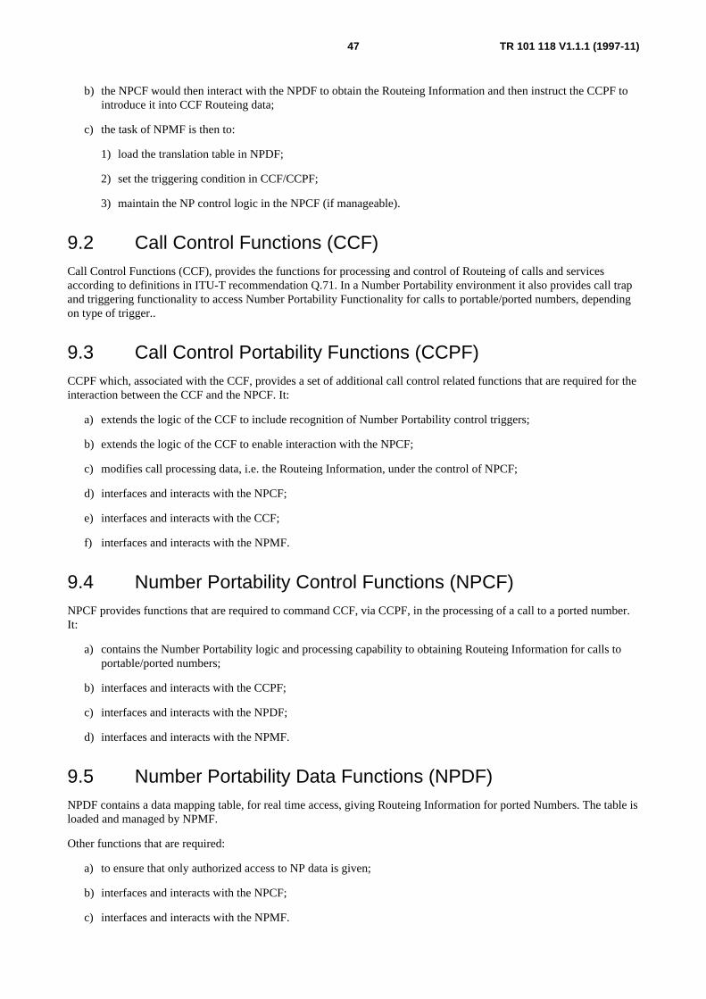
TR 101 118 V1.1.1 (1997-11)47
b) the NPCF would then interact with the NPDF to obtain the Routeing Information and then instruct the CCPF tointroduce it into CCF Routeing data;
c) the task of NPMF is then to:
1) load the translation table in NPDF;
2) set the triggering condition in CCF/CCPF;
3) maintain the NP control logic in the NPCF (if manageable).
9.2 Call Control Functions (CCF)Call Control Functions (CCF), provides the functions for processing and control of Routeing of calls and servicesaccording to definitions in ITU-T recommendation Q.71. In a Number Portability environment it also provides call trapand triggering functionality to access Number Portability Functionality for calls to portable/ported numbers, dependingon type of trigger..
9.3 Call Control Portability Functions (CCPF)CCPF which, associated with the CCF, provides a set of additional call control related functions that are required for theinteraction between the CCF and the NPCF. It:
a) extends the logic of the CCF to include recognition of Number Portability control triggers;
b) extends the logic of the CCF to enable interaction with the NPCF;
c) modifies call processing data, i.e. the Routeing Information, under the control of NPCF;
d) interfaces and interacts with the NPCF;
e) interfaces and interacts with the CCF;
f) interfaces and interacts with the NPMF.
9.4 Number Portability Control Functions (NPCF)NPCF provides functions that are required to command CCF, via CCPF, in the processing of a call to a ported number.It:
a) contains the Number Portability logic and processing capability to obtaining Routeing Information for calls toportable/ported numbers;
b) interfaces and interacts with the CCPF;
c) interfaces and interacts with the NPDF;
d) interfaces and interacts with the NPMF.
9.5 Number Portability Data Functions (NPDF)NPDF contains a data mapping table, for real time access, giving Routeing Information for ported Numbers. The table isloaded and managed by NPMF.
Other functions that are required:
a) to ensure that only authorized access to NP data is given;
b) interfaces and interacts with the NPCF;
c) interfaces and interacts with the NPMF.

TR 101 118 V1.1.1 (1997-11)48
9.6 Number Portability Management Functions (NPMF)NPMF controls the management of Number Portability Data within the domain of a Network. NPMF also possibly addsand or modifies some NP data before data is distributed to the different Network Elements (NPDF). NPMF also requiresthat possible NP data replicated into more than one NE is kept consistent.
In addition it also controls the setting of NP traps/triggers in CCPF and management of NP control logic in NPCF.
9.7 Master Number Portability Management Functions (M-NPMF)
Master Number Portability Management Functions (M-NPMF), controls the management of Number Portability Datawithin one or several Number Portability Domains. This management function may only be needed in case NP data iscentrally managed on a national or European Telephony Numbering Space (ETNS) numbers level.
It also controls:
a) the down loading of NP data to concerned Networks;
b) that only authorized access to NP data is given;
c) authentication of users;
d) shadowing of stored data not to be distributed.
10 Service Provider Portability for Non-GeographicNumbers (NGNP)
In principle the same problems, architectures and solutions are valid/possible for NGNP as for Geographic NumberPortability (GNP) but the main difference is that NP Routeing Number cannot indicate any Recipient Exchange insteadonly Recipient Network, this since the recipient Exchange is determined by the Non Geographic Service Number itselfand by the Recipient Network. This means that NP related procedures, for non geographic numbers, ends whenRecipient Network is reached.
11 Concatenation of service provider portability for Non-Geographic Numbers (NGNP) and GeographicNumbers (GNP)
It should be remembered that a Geographic Number might very well be the output after executing the NGN Service, thisGeographic Number (GN) could in turn be ported, i.e. this means the concatenation of NGNP and GNP is a possibletraffic case. This case is both applicable for call based Routeing and service (SCCP based) Routeing.

TR 101 118 V1.1.1 (1997-11)49
12 High Level examples for management of NPinformation
12.1 General DescriptionManagement of Number Portability Data Base(-s) differ in complexity depending on Network solution, e.g. dependingon if the NP data for a certain ported number only exists within the domain of Donor Network or if NP data is replicatedover a number of Networks.
Number portability domains could e.g. be structured to:
a) all national Geographic Numbers;
b) national Geographic Numbers but per NDC;
c) all national non geographic numbers;
d) national non geographic numbers per type of service;
e) all national Mobile Station ISDN (MSISDN);
f) ETNS numbers.
NOTE: One should not forget that both call based Routeing and SCCP based Routeing need to be managed andthat a least one of the managed network Elements stores the NP data that is accessed in real time.
12.2 NP data is donor network internal businessDespite the case that NP data is not distributed beyond Donor Network there still exists a number of Managementoptions, i.e. one per type of NP DB distribution within the Donor Network.
See figure 27 for a principal Network layout for management of NP data when data maintained within Donor Networkonly.
A d m in is tra t iv eN u m b e r D a ta B a s e
N e tw o rkE le m e n ts (-s )
N e tw o rkE le m e n tM a n a g e m e n tF u n c tio n s
D a ta B a s e
e .g . X .2 5
M F
N E
e .g . X .2 5
D on or N etw ork
Figure 27: Principal network layout for management of np data when data is maintained within donornetwork only
From a management architecture point of view minor modifications are needed when introducing NP and NP data isstored within Donor LE but on the other hand more advanced solutions might be used as well e.g. that NP DB is located

TR 101 118 V1.1.1 (1997-11)50
Exchange external. Regardless location of NP DB, modifications are still needed to allow storage of the NP RouteingInformation.
Despite NP data is maintained Donor network internally there are needs to have bilateral agreements on the content ofNP DB e.g. the structure of Routeing Number. However no new interconnections to management systems are neededsince down loading of NP information, from network external DB, is not needed in this case.
This NP management solution supports only the "onward Routeing" and "Drop-back" NP solutions.
This architecture supports the "Onward Routeing" case only.

TR 101 118 V1.1.1 (1997-11)51
12.3 NP data is centrally managed per portability domainIn the case that NP data is managed per e.g. NDC or charging zones and also that NP data is replicated in severaldifferent network data bases a management architecture according to figure 28 can be foreseen.
D a ta B a s e
D o m ain B
D a ta B a s e
D o m ain N
D a ta B a s e
D o m ain A
A d m in is t ra tiv eN u m b e r D a ta B a s e (-s )
N e tw o rkE le m e n ts
N e tw o rkE le m e n tM a n a g e m e n tF u n c t io n s
e .g . X .2 5
M F M F M F
N E N E N E
e .g . X .2 5
O pe ra to r 1 O pe ra to r 2 O pe ra to r n
M F
e .g . X .2 5
M -M F
M F M F
e .g . X .2 5
M F M a n a g e m e n tF u n c t io n s
M a s te r N u m b e rM a n a g e m e n tF u n c t io n s
Figure 28: Network layout for management of NP data when data is maintained nationally, perportability domain and when NP data is replicated in each of involved operators network
From a management point of view this scenario brings in new interfaces/interconnections to networks for managementof the Number portability data. This solution allows each of the Network providers to manage, e.g. distribute, datawithin their network.
This NP management solution supports all described NP solutions, but is not needed in case of "onward Routeing" and"Drop-back" solutions.
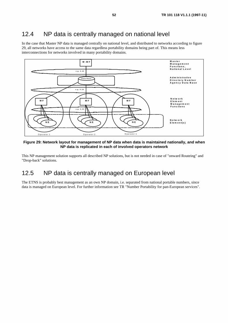
TR 101 118 V1.1.1 (1997-11)52
12.4 NP data is centrally managed on national levelIn the case that Master NP data is managed centrally on national level, and distributed to networks according to figure29, all networks have access to the same data regardless portability domains being part of. This means lessinterconnections for networks involved in many portability domains.
N E
e . g . X . 2 5
N E N E
M F M F M F
A d m in is t r a t iv eD ir e c t o r y N u m b e rA g e n c y D a t a B a s e
N e tw o r kE le m e n tM a n a g e m e n tF u n c t io n s
D a t a B a s e
O p e ra to r 1 O p e ra to r 2 O p e ra to r n
N e tw o r kE le m e n t ( s )
e . g . X . 2 5
M - M F
e . g . X . 2 5
M a s t e rM a n a g e m e n tF u n c t io n s ,N a t io n a l L e v e l
Figure 29: Network layout for management of NP data when data is maintained nationally, and whenNP data is replicated in each of involved operators network
This NP management solution supports all described NP solutions, but is not needed in case of "onward Routeing" and"Drop-back" solutions.
12.5 NP data is centrally managed on European levelThe ETNS is probably best management as an own NP domain, i.e. separated from national portable numbers, sincedata is managed on European level. For further information see TR "Number Portability for pan-European services".

TR 101 118 V1.1.1 (1997-11)53
Annex A
A.1 Current proposals on solutions for Number Portability
A.1.1 IntroductionThere exist a number of different proposals for implementing number portability in the public switched telephonynetwork (PSTN) and the Integrated Services Digital Network (ISDN).
Note, the vocabulary within this annex does not always follow the one used in the main report, instead the vocabularyused reflects the publicly discussed solution.
The proposals can be divided in the following main types:
- central Database;
- drop-back from donor;
- call Forwarding by donor;
- non-Geographic Number.
In the Central Database solutions the databases contain the relationship between the subscriber directory number and arouteing number used for routeing in the network. The actual routeing number can be the subscriber number prefixedwith some kind of operator or even exchange identity or be a pure routeing number, like the Roaming Number used inthe GSM network and in the ETSI CTM drafts.
The Drop-back solutions make use of the 'drop back' feature in the signalling network. When an exchange analyses thecalled number and detects that the number has been ported out from the exchange, the call is released with someinformation that can be used by a proceeding exchange that performs necessary re-routing.
The Call Forwarding solution makes use of the Call Forwarding Unconditional function in the exchange from where thenumber has been ported. The forwarded to number is the address to the current serving network or even exchange of theported subscriber. This solution has the mayor drawback of impacting a lot of Supplementary Services.
The Non-Geographic Number solution requires that when a subscriber is ported for the first time he/she should changeto a non Geographic (e.g. Personal) number. After this the subscriber can keep the number at any future porting. Newsubscribers can immediately receive a non-geographic number like e.g. an UPT number or PN. This solution thenrequires a number portability solution for non geographic numbers only. This solution has not been further elaborated inthis report as it initially will force subscribers to change the directory number. This solution is used in Finland for nationwide NP.
Several solutions/methods have been proposed for providing number portability, the different methods can be groupedas follows:
Call Forwarding methods:
- Simple Call Forwarding Unconditional (CFU);
- Remote Call Forwarding (RCF).
Drop-back methods:
- Query on Release (QoR);
- Return to Pivot (RTP).
Central Database methods:
- Call Completion to Portable Number (CCPN);
TR 101 118 V1.1.1 (1997-11)54
- Local Area Number Portability (LANP);
- Carrier Portability Code (CPC);
- Network Routeing Prefix (NRP);
- Generic Routeing Method (GRM);
- Query on Release (QoR).
A.1.2 Simple Call Forwarding Unconditional (CFU)In the described example the Call Forwarding Unconditional (CFU) function is used to reroute the call from the donorexchange to the recipient network or/and exchange.
The additional problem with this solution, compared to Remote Call Forwarding, is that the CLI as presented to calledparty might indicate the called party number since this is the number that caused the forwarding in the donor exchange.Depending on Call Forwarding parameters used also some Supplementary services (e.g. U-U-1) might not work, i.e. it isan option weather or not U-U-1 shall be transported at call forwarding.
Problem areas are otherwise similar as the ones for RCF.
This solution is only regarded as a very interim such.
A.1.3 Remote Call Forwarding (RCF)In the Remote Call Forwarding differs from the Call Forwarding function in the way that it allow for correct presentationof CLI and does not restrict supplementary services being forwarded transparently to recipient exchange/network (it canbe compared with Onward routeing in the main report).
The main drawbacks are that since the donor exchange is involved, the service level of the call is depending on the oneavailable on the used interconnection protocols and the donor exchange. One should also consider services that normallydo not work over operator borders are e.g. (Carrier Selection (CS), CUG, U-U. The CUG and U-U services might resultin call being released at the interconnection point due to service requirements, e.g. CUG without outgoing access or U-U-1 essential. Regarding the CS we might have legal problems since CS decision might be wrong by the donor, it canalso be questioned if the donor network is allowed to be routed through at all if CS tells else.
One can here consider the case that originating and destination network operators have agreements on transfer/inter-networking for CLIP, COLP, CUG, CS and U-U but the same agreements do not exist between donor and recipientnetwork, i.e. the service level would differ for calls to ported subscribers compared to calls to non ported subscribers.One can also assume that cost effective routeing can not be performed with this type of solution, the call might in worstcase be trombone back to originating network.
The solution is in service in UK and is planned for Germany. Both UK and Germany forward the call by using a prefix5xxxxx and Dxxx respectively but without modifying the NOA. France intend to use x0xxx as identification of arouteing number.
A.1.4 Return To Pivot (RTP)This is a method originally proposed by Pacific Bell but already exists as different variants in a number of markets, thisis the method that usually is referred to as Drop-back.
RTP uses extended switching capabilities to accomplish portability. Calls using RTP will attempt to complete, as theypresently do, to a switch that is assigned the dialled number serie. If the dialled number has been ported from the switch,the call will be released back to a previous switch (Pivot switch) in the call path for re-routing to its new location.
The re-routing information (RI), obtained from a central database or locally stored in the switch, are included in therelease message sent back in the network to be able to reach the new location from the re-routing exchange. The Pivotswitch indicates to succeeding exchanges with information (CI) sent in set-up message that it is Pivot capable and thusdrop-back is possible.
TR 101 118 V1.1.1 (1997-11)55
This method is not seen as a long term solution for the introduction of service provider portability since it favours theincumbent service providers. Even though a subscriber has been ported to another service provider all calls will first bedirected to the donor service provider which then will have control over the call. This also means that the donor serviceprovider will be favoured since resources are used in its domain and accounts has to be settled which then favours thedonor service provider.
The method also prohibits the service provider of the originating switch to perform optimal routeing in its own networkbefore eventually breaking out to another service providers network. As a rule, a service provider would like to keep thecall within its own network as long as possible to avoid unnecessary settlements of accounts between operators.
This method could though be used for location portability, but when the number of ported subscribers increases this willcause inefficient routeing and bad utilization of network resources.
A.1.5 Query on Release (QoR)This is a method originally proposed by Nortel.
This feature is very similar as Return To Pivot. When using QoR the initiating switch sets a QoR attempt indicator androutes the call to the donor service providers switch. The switch determines whether it serves the called user. If it doesnot serve the called user and the call request contains the QoR attempt indicator, it releases the call back to theoriginating switch with an indication that the user is no longer served on the donors switch. The donors switch handlesall other calls using existing procedures.
Based on the release information, the initiating switch obtains a network routeing number for the called user'sterminating switch, clears the QoR attempt indicator, and completes the call. The network routeing number can beobtained by the originating switch by interrogating a database located either internally in the switch or external from theswitch.
A.1.6 Call Completion to Portable Number (CCPN)This is a method originally proposed by AT&T, and is in US considered the best long-term solution for the wirelinenetworks in US. AT&T has also a proposal for wireless networks which uses the AT&T LRN scheme for call set-up.
As it seems now, US will go for the CCPN solution and work is already being done in ANSI T1S1 to include the CCPNmethod in the ANSI standard.
In this method, each portable number is associated with a Network Routeing Number (NRN) for this switch. When anumber is dialled by a calling subscriber to reach the intended subscriber, the first switch that can query a numberportability database will do so. The response will be the NRN which is the node address to the switch were the calledsubscriber is served.
The method proposes an modification of the ISUP signalling system, so that the NRN will be included as CdPN in theset up message to be sent off and used for further routeing in the network. The dialled digits will be included in GenericNumber (in US called Generic Address Parameter, GAP) with a new number qualifier. A new field in Forward CallIndicator will be set to indicate if a database query has been performed, this to prevent several queries to be made.
The terminating switch will substitute the NRN included in CdPN with the actual dialled digits stored in GenericNumber parameter and do a seizure attempt towards the called subscriber.
The Service Management aspects include both updates of the database as well as updating of GTT data. This means thatthere is a need for each ported subscriber to have an update in the Signalling Transfer Point (STP), translation data, forsome subscriber services such as CCBS, CCNR and SMS services. This means that the updates to the database and theGTT data should be synchronized and handled within one transaction to maintain consistency. The subscriber lineallocation/de-allocation is not taken into consideration. This is also valid for the next method described.
A proposal exists to also solve the SCCP using services by use of same database(-s), this by introducing a QoRprocedure in the SCCP. SCCP shall then make the DB query in the case a SCCP message is rejected (by donor). Theretrieved data is optionally also stored in the GTA, i.e. GTT will then be self provisioning. After this procedure theSCCP message is re-routed to recipient exchange.

TR 101 118 V1.1.1 (1997-11)56
The main drawbacks with this solution are that the SCCP tables will after a while be enormous and that donorexchange/network is loaded with failing SCCP messages a period after that a subscriber is ported out.
A.1.7 Local Area Number Portability (LANP)This is a method originally proposed by U.S Intelco, Stratus Computer and Electric Lightwave Inc.
The LANP method is functionally a superset of LRN, the main difference between the CCPN and LANP methods is thatthe LANP only defines the inter-work interfaces in the network, but does not mandate or constrain the internalimplementation in switches of the NP functionality amongst competing carriers.
The LANP method uses two "domains" of 10-digit numbers to route telephone calls to customer that have transferredthe numbers to new carriers or new geographic locations. Specifically, LANP assigns a ten-digit customer numberaddress (CNA) to each subscriber; this is the number that callers would dial to place telephone calls to the particularsubscriber. It also assigns each customer a 10-digit network address (NNA) that identifies where in the telephonenetwork to reach the particular subscriber. Both the CNA and NNA are stored in routeing databases so that carriers candetermine from the dialled number where in the network to reach the called party.
The LANP method does not mandate how a specific NNA is interpreted in the terminating switch of a ported line, eitherthe CNA or NNA values may be used to translate the incoming call to the intended subscriber facilities.
In other words, the LANP is functionally a superset of CCPN, as the NNA can be assigned the NRN value and CNA canbe used to locate the subscribers facilities in the same way as in the CCPN method.
The method proposes the same modification of the signalling system as the CCPN method.
A.1.8 Carrier Portability Code (CPC)This is a method originally proposed by MCImetro.
CPC is a method that uses a Number Portability database to obtain the routeing information necessary to terminate callsto subscribers that have been ported. Each service provider are assigned a unique three-digit Carrier Portability Code(CPC) in each number portability area (within a LATA). To be noticed is that CPCs and NPAs are not allowed tooverlap which then also means that CPCs can be reused in another portability area i.e. LATA.
As can be seen from this method is that the called party number is destroyed since the NPA part of the NANP number isreplaced with the CPC. One of the reasons for this is that the number length in US is always 7 or 10 digits. If the CPCjust would be prefixed to the called party number this would most probably cause major impact on existing switchingsystems in US.
The CPC method does not require any updates of the signalling systems, both the Multi-Frequency (MF) and SignallingSystem 7 (SS7) can be used.
The CPC method is related to the Network Routeing Prefix (NRP) solution, the main difference is that in NRP solution aprefix is added to the called party number which means that the dialled number is not destroyed which is the case forCPC.
A.1.9 Network Routeing Prefix (NRP)The main principle is the same as the LRN (the use of a central database) and CPC (routeing principle) methods, TheNRP method is based on using a central database to administer all the addresses and have the relation between asubscriber directory number and the address to which node the subscriber resides on in form of a Network RouteingPrefix (NRP). No new signalling information is required compared to both LRN and NRA.
The NRP might either indicate the receiving operators network (gateway) or indicate the full address to the recipientexchange. An other difference is that it proposes using the Type Of Number (TON) to indicate that the CdPN containsNRP + Called Party Number, this saves digits in the CdPN, e.g. the starting 5 and 7 in the UK and German solutions canbe omitted in transmissions. The method also allows for several TON values to be used, e.g. one value indicating NRPbeing a Network ID and an other telling Exchange ID.

TR 101 118 V1.1.1 (1997-11)57
When a call is made towards a subscriber, the dialled digits are analysed in the originating local exchange and a query isdone towards a central database to get the NRP. The NRP is added as a prefix before the called subscriber number. NRPis then used for routeing the call to the called party network or to the recipient switch if the called party is within homenetwork.
In the recipient LE the NRP is recognized as "own" and removed, thereafter the number is used for performing the callset up according to existing principles. The NRP can optionally be removed, in the gateway exchange prior leaving toother network, in case the other network uses an own DB for its network internal routeing. This then results in no extrainformation being sent on operator borders.
The method does not require any modifications of the signalling systems. A specific value of the TON is used to indicatethe existence of NRP and implicitly also that a database query has been performed.
The Service Management aspects includes only SMS updates of the portability database. It is assumed that the numberseries are defined in the LE by ordinary LE management systems. This leaves the update of moved subscribers in thedatabase to the SMS system.
The database Query could optionally be performed in the first transit exchange in the originating Network.
A.1.10 Generic Routeing Method (GRM)This solution has originally been proposed by KPN.
The Generic Routeing Method is very similar to CCPN solution, the main difference is that the database query is onlyperformed either prior to leaving the originating network or as a QoR procedure.
The NRN is not sent over operator borders.
This solution has some advantages since it does not involve the donor network. It requires similar modifications in thesignalling protocols as the NRN solution.

TR 101 118 V1.1.1 (1997-11)58
History
Document history
V1.1.1 November 1997 Publication
ISBN 2-7437-1815-3Dépôt légal : Novembre 1997


![Revision and Exam Tips - New SMART website · =====trtrt]=-tr-trtrtrtrtrtr-tr F 1F]ilflfrritfltrft tr-trtr=tr tr=tr==tr tr-tlF-lflft 71 trtr=trtrtr=tr trtrtrtrtr=trtr trtrtrtrtr==tr](https://static.fdocuments.in/doc/165x107/5ed679a2e7ed90307a0783ea/revision-and-exam-tips-new-smart-trtrt-tr-trtrtrtrtrtr-tr-f-1filflfrritfltrft.jpg)