Tpe CCM for 44 C2 - assets.danfoss.com · • MOPD up to 50 bar (725 psi). • Combined stainless...
13
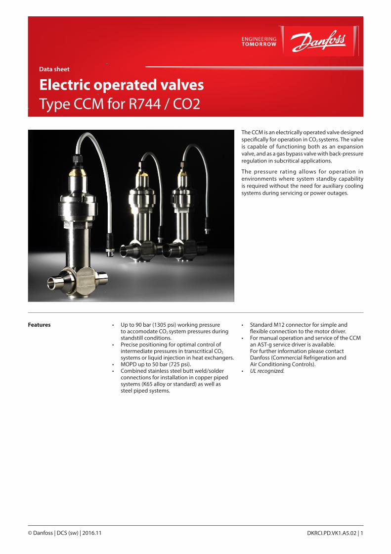
The CCM is an electrically operated valve designed specifically for operation in CO2 systems. The valve is capable of functioning both as an expansion valve, and as a gas bypass valve with back-pressure regulation in subcritical applications. The pressure rating allows for operation in environments where system standby capability is required without the need for auxiliary cooling systems during servicing or power outages. Features • Up to 90 bar (1305 psi) working pressure to accomodate CO2 system pressures during standstill conditions. • Precise positioning for optimal control of intermediate pressures in transcritical CO2 systems or liquid injection in heat exchangers. • MOPD up to 50 bar (725 psi). • Combined stainless steel butt weld/solder connections for installation in copper piped systems (K65 alloy or standard) as well as steel piped systems. • Standard M12 connector for simple and flexible connection to the motor driver. • For manual operation and service of the CCM an AST-g service driver is available. For further information please contact Danfoss (Commercial Refrigeration and Air Conditioning Controls). • UL recognized. Data sheet Electric operated valves Type CCM for R744 / CO2 DKRCI.PD.VK1.A5.02 | 1 © Danfoss | DCS (sw) | 2016.11
Transcript of Tpe CCM for 44 C2 - assets.danfoss.com · • MOPD up to 50 bar (725 psi). • Combined stainless...
The CCM is an electrically operated valve designed specifically for operation in CO2 systems. The valve is capable of functioning both as an expansion valve, and as a gas bypass valve with back-pressure regulation in subcritical applications.
The pressure rating allows for operation in environments where system standby capability is required without the need for auxiliary cooling systems during servicing or power outages.
Features • Up to 90 bar (1305 psi) working pressure to accomodate CO2 system pressures during standstill conditions.• Precise positioning for optimal control of intermediate pressures in transcritical CO2 systems or liquid injection in heat exchangers.• MOPD up to 50 bar (725 psi).• Combined stainless steel butt weld/solder connections for installation in copper piped systems (K65 alloy or standard) as well as steel piped systems.
• Standard M12 connector for simple and flexible connection to the motor driver.• For manual operation and service of the CCM an AST-g service driver is available. For further information please contact Danfoss (Commercial Refrigeration and Air Conditioning Controls).• UL recognized.
Data sheet
Electric operated valvesType CCM for R744 / CO2
DKRCI.PD.VK1.A5.02 | 1© Danfoss | DCS (sw) | 2016.11

Stepper motor switch sequence:
CCM valve Connector Cable plug
4 Black 4
3 White 3
2 Green 2
1 Red 1
Connection 1 Wire Color Connection 2
Pin Out
Electrical data
Stepper motor switch sequence:
CLOSING
STEPCoil I Coil II
OPENING
Red Green White Black
1 + - + -
2 + - - +
3 - + - +
4 - + + -
1 + - + -
Parameter CCM
Motor enclosure IP 67
Stepper motor type Bi-polar - permanent magnet
Step mode 2 phase full step
Phase resistance 52Ω ±10%
Phase inductance 85 mH
Holding current Depends on application.Full current allowed (100% duty cycle)
Step angle 7.5° (motor), 0.9° (lead screw),Gearing ration 8.5:1. (38/13)2:1
Nominal voltage (Constant voltage drive) 12 V dc -4% +15%, 150 steps/sec.
Phase current (Using chopper drive) 100 mA RMS -4% +15%,
Max. total power Voltage / current drive: 5.5 / 1.3 W (UL: NEC class 2)
Step rate 150 steps/sec. (constant voltage drive)0-300 steps/sec. 300 recommended (chopper current drive)
Total steps CCM 10, 20, 30 2625 [+160 / -0] stepsCCM 40 3530 [+160 / -0] steps
Total stroke 13 mm / 16 mm (0.5 in. / 0.6 in.)
Full travel time CCM 10, 20, 30 17 / 8.5 sec. (voltage / current)CCM 40 23 / 11.5 sec. (voltage / current)
Lifting height CCM 10, 20, 30 13 mm (0.5 in.)CCM 40 16 mm (0.6 in.)
Reference position Overdriving against the full close position
Electrical connection 4 wire 0.5 mm2 (0.02 in2), 0.3 m (1 ft) long cable
Danfoss93G300.10
Danfoss93G301.10
Technical data Parameter CCM
Compatibility R744
MOPD 50 bar (725 psi)
Max. working pressure (PS/MWP) 90 bar (1305 psi)
Refrigerant temperature range –40°C to 60°C (–40°F to 140°F)
Ambient temperature –40°C to 60°C (–40°F to 140°F)
Material of construction Stainless steel
Data sheet | Electrically operated valves for CO2, type CCM
© Danfoss | DCS (sw) | 2016.11 DKRCI.PD.VK1.A5.02 | 2

Design
1. Cable 2. Glass seal 3. Motor housing 4. Stepper motor 5. Bearing 6. Spindle 7. Insert 8. Valve piston 9. Valve seat 10. Valve port
Ordering Valve incl. actuator - Single pack
TypeKV
m3/h
Connections (Combi) Code nos single packWeld1)
[in]Solder
ODF x ODF [in]CCM 10 0.8 1/2 x 1/2 5/8 x 5/8 027H7188CCM 20 1.7 3/4 x 3/4 7/8 x 7/8 027H7187CCM 30 2.5 1 x 1 1 1/8 x 1 1/8 027H7186CCM 40 4.2 1 x 1 1 1/8 x 1 1/8 027H71851) OD according to EN 10220
Spareparts:
Type Description Code number
AST Actuator for CCM CO2 valve 027H7184
O-ring spare part kit for CCM/CCMT (2 O-rings) 027H7230
Accessories:
Type Description Code number
Cable with M12 connector - 8 meter (26.2 ft.) 034G2323
AST-G Manual valve driver for service 034G0013
Data sheet | Electrically operated valves for CO2, type CCM
© Danfoss | DCS (sw) | 2016.11 DKRCI.PD.VK1.A5.02 | 3

34G210.10A2 black
A1 white
B1 red
B2 green
34G211.10
M12 angle female connector is intended for use with a standard M12 male connector, available on stepper motor valves.This cable is designed to offer high flexibility and small outer diameters with tensile strength.The angle way M12 cable consist of paired, twisted wires, which decreases mutual influence between signals transmitted along the cable and reduces influence of external sources of interference. The cables thus provides a higher degree of protection against lost steps compared to other cables.
Accessories: M12 angle cable
Jacket PVC - black
Cable outer sheath Oil - resistant
Water proof rating IP 67
Operating temperature range -40 – +80 °C
Wire type Twisted pair, cross section 20 AWG / 0.5 mm2
Cable outer diameter 7.0 mm
Minimum bending radius 10 x cable diameter
Cable combustibility / test Flame retardant / VW-1 / CSA FT - 1
M12 standard EN 61076-2-101
Reference standard UL style 2464 and DIN VDE 0812
LVD directive 73/23/EEC and 93/68/EEC
Cable Cable length (L) Insulation Packing format Code no.
PVC - black2 m / 6.6 ft SR-PVC Single pack 034G7073
8 m / 26.2 ft SR-PVC Single pack 034G7074
Approvals
Specification
Ordering
IdentificationProduct typeCode no
Manufacturing date
Meters / Feets
Country
RoHS
Dimensions
34G209.10
49 mm / 1.9 inch35 mm / 1.4 inch2 meters / 6.6 feet
8 meters / 26.2 feet
Ø 63 mm / 1/4 inch
Connections
Data sheet | Electrically operated valves for CO2, type CCM
© Danfoss | DCS (sw) | 2016.11 DKRCI.PD.VK1.A5.02 | 4

Valve operation The CCM can be used in a variety of applications within CO2 refrigeration systems. Typically it is
Application 1
A gas bypass valve is typically used to regulate the intermediate pressure in a transcritical CO2
refrigeration system. By venting flashgas generated after the transcritical expansion, the pressure can
used as a gas bypass valve in a transcritical CO2
booster system or as an expansion valve.
From cases
Product type Diagram
File name R64-2046
Date I.S. 2010.06.01
AKS2050
AKS 2050EKC326A
ICMTS
To cases
CCM
Dan
foss
R64
-204
6.11
be kept at a safe level for all components situated in the liquid lines of a transcritical CO2 system. For use in the gas bypass application the EKC326A controller is recommended.
Product type Diagram
File name R64-2045
Date I.S. 2010.06.01
CCMD
anfo
ssR
64-2
045.
11
AKS 33AKS 11
EKC 316A
EVR
GBCGBC
Application 2
A liquid expansion valve is typically used for injection in plate heat exchangers of CO2/CO2 cascades, or as an expansion valve for CO2 evaporators. For the
liquid injection applications CCM is used with EKC 316A controller.
Data sheet | Electrically operated valves for CO2, type CCM
© Danfoss | DCS (sw) | 2016.11 DKRCI.PD.VK1.A5.02 | 5

Sizing and capacities The following tables indicate nominal capacities of the valve in the gas bypass application and in the liquid expansion application with R744 (CO2) as refrigerant. Capacities are given for varying operating conditions within the normal range
of the valve. If the capacity shown in the table is higher than 75% of the required capacity, then it is recommended to use a valve one size larger, or as an alternative, to use an additional valve in parallel.
Valve operation (Cont.)
Data sheet | Electrically operated valves for CO2, type CCM
© Danfoss | DCS (sw) | 2016.11 DKRCI.PD.VK1.A5.02 | 6

Gas Bypass Application The capacities shown are based on the amount of flash gas produced when expanding from supercritical CO2 before the transcritical expansion valve (ICMTS) at 35°C and the corresponding
optimal high pressure setting (89 bar) as set by the Danfoss EKC326A controller. The capacities shown are the total system evaporating capacity at the given evaporating temperature.
CCM 10Gas cooler
Outlet [°C] 20 22 24 26 28 30 32 34 36 38 40 42 44 46 48 50
Pressure [bar] 60.7 63.6 66.5 69.4 72.3 76.4 81.6 86.8 92.0 97.2 102.4 107.6 112.8 118.0 123.2 128.4
Receiver [°C]
NT evap. [°C] Capacity [kW]
15
10 343.0 225.1 158.7 115.4 83.7 91.8 81.3 72.9 66.0 60.1 55.1 50.8 46.9 43.4 40.3 37.4
5 459.3 301.4 212.5 154.5 112.1 122.9 108.8 97.6 88.3 80.5 73.8 68.0 62.8 58.1 53.9 50.1
0 531.8 349.1 246.1 178.9 129.8 142.4 126.0 113.0 102.3 93.2 85.5 78.7 72.7 67.3 62.5 58.1
-5 579.7 380.5 268.3 195.0 141.4 155.2 137.4 123.2 111.5 101.6 93.2 85.8 79.2 73.4 68.1 63.3
-10 610.9 400.9 282.7 205.5 149.0 163.5 144.7 129.8 117.5 107.1 98.2 90.4 83.5 77.3 71.7 66.7
10
5 183.3 141.0 110.2 86.3 66.4 71.7 64.8 59.1 54.3 50.1 46.4 43.2 40.3 37.6 35.2 33.0
0 243.5 187.3 146.4 114.6 88.2 95.3 86.1 78.5 72.1 66.5 61.7 57.4 53.5 50.0 46.7 43.8
-5 279.6 215.1 168.1 131.6 101.3 109.4 98.8 90.1 82.8 76.4 70.8 65.9 61.4 57.4 53.7 50.3
-10 302.1 232.4 181.6 142.2 109.5 118.2 106.8 97.4 89.4 82.6 76.6 71.2 66.4 62.0 58.0 54.3
-15 315.4 242.6 189.6 148.4 114.3 123.4 111.5 101.7 93.4 86.2 79.9 74.3 69.3 64.7 60.6 56.7
5
0 125.2 102.3 83.8 68.2 54.3 58.1 53.2 49.0 45.4 42.2 39.4 36.9 34.6 32.5 30.6 28.8
-5 165.1 134.9 110.5 89.9 71.6 76.6 70.1 64.6 59.9 55.7 52.0 48.7 45.7 42.9 40.4 38.0
-10 188.1 153.7 125.9 102.5 81.6 87.3 79.9 73.6 68.2 63.5 59.3 55.5 52.1 48.9 46.0 43.3
-15 201.6 164.8 135.0 109.8 87.5 93.6 85.6 78.9 73.1 68.0 63.5 59.5 55.8 52.4 49.3 46.4
-20 208.6 170.5 139.7 113.7 90.6 96.9 88.6 81.7 75.7 70.4 65.8 61.6 57.7 54.2 51.0 48.0
0
-5 93.4 78.8 66.4 55.3 45.1 47.9 44.2 41.0 38.2 35.8 33.6 31.6 29.8 28.1 26.5 25.1
-10 122.3 103.3 86.9 72.5 59.0 62.8 57.9 53.7 50.1 46.9 44.0 41.4 39.0 36.8 34.7 32.8
-15 138.3 116.8 98.3 82.0 66.8 71.0 65.5 60.8 56.7 53.0 49.8 46.8 44.1 41.6 39.3 37.1
-20 147.1 124.2 104.6 87.2 71.0 75.5 69.7 64.6 60.3 56.4 52.9 49.8 46.9 44.2 41.8 39.5
-5
-10 72.6 62.6 53.7 45.5 37.7 39.9 37.0 34.5 32.3 30.4 28.6 27.0 25.5 24.1 22.9 21.7
-15 94.5 81.5 69.8 59.2 49.0 51.9 48.1 44.9 42.0 39.5 37.2 35.1 33.2 31.4 29.8 28.2
-20 106.1 91.5 78.5 66.5 55.1 58.3 54.1 50.4 47.2 44.4 41.8 39.5 37.3 35.3 33.4 31.7
-25 112.0 96.6 82.8 70.2 58.1 61.5 57.1 53.2 49.8 46.8 44.1 41.6 39.4 37.2 35.3 33.4
-10
-15 57.8 50.5 43.9 37.7 31.6 33.3 31.0 29.1 27.3 25.7 24.3 23.0 21.8 20.7 19.6 18.6
-20 74.7 65.3 56.7 48.7 40.8 43.0 40.1 37.5 35.3 33.3 31.4 29.7 28.2 26.7 25.4 24.1
-25 83.3 72.9 63.3 54.3 45.5 48.0 44.7 41.9 39.4 37.1 35.1 33.2 31.4 29.8 28.3 26.9
-30 87.3 76.3 66.3 56.9 47.7 50.3 46.8 43.9 41.2 38.9 36.7 34.8 32.9 31.2 29.6 28.2
-15
-20 46.6 41.2 36.1 31.3 26.4 27.8 26.0 24.4 23.0 21.8 20.6 19.6 18.6 17.6 16.8 16.0
-25 59.8 52.8 46.3 40.1 34.0 35.7 33.4 31.4 29.6 27.9 26.5 25.1 23.8 22.6 21.5 20.5
-30 66.2 58.5 51.3 44.4 37.6 39.5 37.0 34.7 32.7 30.9 29.3 27.8 26.4 25.1 23.8 22.7
-35 68.8 60.8 53.3 46.2 39.1 41.1 38.4 36.1 34.0 32.2 30.5 28.9 27.4 26.1 24.8 23.6
Data sheet | Electrically operated valves for CO2, type CCM
© Danfoss | DCS (sw) | 2016.11 DKRCI.PD.VK1.A5.02 | 7

CCM 20Gas cooler
Outlet [°C] 20 22 24 26 28 30 32 34 36 38 40 42 44 46 48 50
Pressure [bar] 60.7 63.6 66.5 69.4 72.3 76.4 81.6 86.8 92.0 97.2 102.4 107.6 112.8 118.0 123.2 128.4
Receiver [°C]
NT evap. [°C] Capacity [kW]
15
10 686.1 450.3 317.5 230.7 167.4 183.6 162.6 145.7 131.9 120.3 110.3 101.5 93.8 86.8 80.6 74.9
5 918.6 602.9 425.1 308.9 224.1 245.9 217.7 195.1 176.6 161.0 147.6 135.9 125.5 116.3 107.9 100.3
0 1064 698.1 492.2 357.7 259.5 284.7 252.0 226.0 204.5 186.5 170.9 157.4 145.4 134.6 124.9 116.1
-5 1159 761.0 536.6 390.0 282.9 310.4 274.7 246.3 222.9 203.3 186.3 171.5 158.5 146.7 136.2 126.6
-10 1222 801.9 565.4 410.9 298.1 327.0 289.5 259.5 234.9 214.2 196.3 180.8 167.0 154.6 143.5 133.4
10
5 366.5 282.0 220.4 172.5 132.8 143.4 129.6 118.2 108.5 100.2 92.9 86.4 80.5 75.2 70.4 65.9
0 486.9 374.6 292.7 229.2 176.4 190.5 172.2 157.0 144.2 133.1 123.4 114.7 107.0 99.9 93.5 87.6
-5 559.2 430.2 336.1 263.2 202.6 218.8 197.7 180.3 165.6 152.8 141.7 131.8 122.9 114.8 107.4 100.6
-10 604.2 464.8 363.2 284.3 218.9 236.4 213.6 194.8 178.9 165.2 153.1 142.4 132.7 124.0 116.0 108.7
-15 630.8 485.3 379.2 296.9 228.5 246.8 223.0 203.4 186.8 172.4 159.8 148.6 138.6 129.5 121.1 113.4
5
0 250.3 204.6 167.6 136.4 108.6 116.2 106.3 98.0 90.8 84.5 78.9 73.8 69.3 65.1 61.2 57.6
-5 330.1 269.8 221.0 179.9 143.3 153.3 140.2 129.2 119.7 111.4 104.0 97.4 91.4 85.8 80.7 76.0
-10 376.2 307.5 251.9 205.0 163.3 174.7 159.8 147.2 136.4 127.0 118.6 111.0 104.1 97.8 92.0 86.6
-15 403.2 329.6 269.9 219.7 175.0 187.2 171.3 157.8 146.2 136.1 127.1 119.0 111.6 104.8 98.6 92.8
-20 417.3 341.1 279.4 227.4 181.1 193.8 177.3 163.3 151.3 140.8 131.5 123.1 115.5 108.5 102.1 96.1
0
-5 186.7 157.7 132.7 110.7 90.2 95.9 88.4 82.0 76.5 71.6 67.2 63.2 59.5 56.2 53.0 50.1
-10 244.5 206.5 173.9 144.9 118.1 125.6 115.8 107.5 100.2 93.8 88.0 82.8 78.0 73.6 69.5 65.6
-15 276.7 233.6 196.7 164.0 133.6 142.0 131.0 121.6 113.3 106.1 99.5 93.6 88.2 83.2 78.6 74.2
-20 294.2 248.5 209.2 174.4 142.1 151.1 139.3 129.3 120.5 112.8 105.9 99.6 93.8 88.5 83.6 79.0
-5
-10 145.3 125.2 107.4 91.0 75.3 79.7 74.0 69.0 64.6 60.7 57.2 54.0 51.0 48.3 45.7 43.3
-15 189.0 162.9 139.7 118.4 98.0 103.7 96.3 89.8 84.1 79.0 74.4 70.3 66.4 62.8 59.5 56.4
-20 212.3 183.0 156.9 133.0 110.1 116.5 108.1 100.8 94.5 88.8 83.6 78.9 74.6 70.6 66.8 63.3
-25 224.1 193.1 165.6 140.4 116.2 123.0 114.1 106.4 99.7 93.7 88.3 83.3 78.7 74.5 70.6 66.9
-10
-15 115.6 101.1 87.8 75.3 63.1 66.6 62.0 58.1 54.6 51.5 48.6 46.0 43.6 41.4 39.3 37.3
-20 149.4 130.6 113.5 97.4 81.6 86.1 80.2 75.1 70.6 66.5 62.9 59.5 56.4 53.5 50.8 48.2
-25 166.6 145.7 126.6 108.6 91.0 96.0 89.4 83.8 78.7 74.2 70.1 66.4 62.9 59.6 56.6 53.8
-30 174.5 152.6 132.6 113.7 95.3 100.5 93.7 87.7 82.5 77.7 73.4 69.5 65.9 62.5 59.3 56.3
-15
-20 93.1 82.3 72.2 62.5 52.9 55.6 52.0 48.9 46.1 43.5 41.2 39.1 37.1 35.3 33.5 31.9
-25 119.6 105.7 92.7 80.3 67.9 71.4 66.8 62.8 59.1 55.9 52.9 50.2 47.7 45.3 43.1 41.0
-30 132.4 117.0 102.6 88.9 75.2 79.1 74.0 69.5 65.5 61.9 58.6 55.6 52.8 50.2 47.7 45.4
-35 137.6 121.6 106.7 92.4 78.1 82.2 76.9 72.2 68.1 64.3 60.9 57.8 54.9 52.1 49.6 47.2
Gas Bypass Application (continued)
Data sheet | Electrically operated valves for CO2, type CCM
© Danfoss | DCS (sw) | 2016.11 DKRCI.PD.VK1.A5.02 | 8

CCM 30Gas cooler
Outlet [°C] 20 22 24 26 28 30 32 34 36 38 40 42 44 46 48 50
Pressure [bar] 60.7 63.6 66.5 69.4 72.3 76.4 81.6 86.8 92.0 97.2 102.4 107.6 112.8 118.0 123.2 128.4
Receiver [°C]
NT evap. [°C] Capacity [kW]
15
10 1029 675.4 476.2 346.1 251.1 275.5 243.8 218.6 197.9 180.4 165.4 152.3 140.6 130.2 120.9 112.3
5 1378 904.3 637.6 463.4 336.2 368.8 326.5 292.7 264.9 241.5 221.4 203.9 188.3 174.4 161.8 150.4
0 1595 1047 738.3 536.6 389.3 427.1 378.0 338.9 306.8 279.7 256.4 236.0 218.0 201.9 187.4 174.2
-5 1739 1142 804.9 584.9 424.3 465.5 412.1 369.5 334.4 304.9 279.5 257.3 237.7 220.1 204.3 189.9
-10 1833 1203 848.1 616.4 447.1 490.6 434.2 389.3 352.4 321.3 294.5 271.1 250.5 231.9 215.2 200.1
10
5 549.8 423.0 330.5 258.8 199.2 215.1 194.4 177.3 162.8 150.3 139.3 129.6 120.8 112.8 105.6 98.9
0 730.4 561.9 439.1 343.7 264.6 285.8 258.2 235.5 216.2 199.6 185.1 172.1 160.5 149.9 140.2 131.3
-5 838.7 645.2 504.2 394.7 303.9 328.2 296.5 270.4 248.3 229.3 212.5 197.7 184.3 172.1 161.0 150.8
-10 906.3 697.2 544.8 426.5 328.4 354.6 320.4 292.2 268.3 247.7 229.7 213.6 199.1 186.0 174.0 163.0
-15 946.2 727.9 568.8 445.3 342.8 370.2 334.5 305.1 280.1 258.6 239.8 223.0 207.9 194.2 181.7 170.1
5
0 375.5 306.9 251.4 204.6 163.0 174.4 159.5 147.0 136.2 126.7 118.3 110.8 103.9 97.6 91.8 86.4
-5 495.2 404.7 331.5 269.8 214.9 229.9 210.3 193.8 179.6 167.1 156.1 146.1 137.0 128.7 121.1 114.0
-10 564.3 461.2 377.8 307.4 244.9 262.0 239.7 220.9 204.6 190.5 177.8 166.5 156.2 146.7 138.0 129.9
-15 604.8 494.3 404.9 329.5 262.5 280.8 256.9 236.7 219.3 204.1 190.6 178.4 167.4 157.2 147.9 139.2
-20 625.9 511.6 419.1 341.0 271.7 290.7 265.9 245.0 227.0 211.3 197.3 184.7 173.2 162.7 153.1 144.1
0
-5 280.1 236.5 199.1 166.0 135.2 143.8 132.6 123.1 114.7 107.4 100.8 94.8 89.3 84.2 79.5 75.2
-10 366.8 309.8 260.8 217.4 177.1 188.3 173.7 161.2 150.3 140.6 132.0 124.1 117.0 110.3 104.2 98.4
-15 415.0 350.5 295.0 246.0 200.4 213.1 196.5 182.3 170.0 159.1 149.3 140.4 132.3 124.8 117.9 111.4
-20 441.3 372.7 313.8 261.6 213.1 226.6 209.0 193.9 180.8 169.2 158.8 149.4 140.7 132.7 125.3 118.4
-5
-10 217.9 187.8 161.0 136.5 113.0 119.6 111.0 103.5 96.9 91.1 85.8 81.0 76.6 72.4 68.6 65.0
-15 283.5 244.4 209.5 177.6 147.0 155.6 144.4 134.7 126.1 118.5 111.7 105.4 99.6 94.3 89.3 84.6
-20 318.4 274.5 235.4 199.5 165.2 174.8 162.2 151.3 141.7 133.1 125.4 118.4 111.9 105.9 100.3 95.0
-25 336.1 289.7 248.4 210.6 174.3 184.5 171.2 159.7 149.5 140.5 132.4 124.9 118.1 111.7 105.8 100.3
-10
-15 173.4 151.6 131.7 113.0 94.7 99.9 93.1 87.2 81.9 77.2 73.0 69.1 65.4 62.1 58.9 55.9
-20 224.1 196.0 170.2 146.1 122.4 129.1 120.3 112.6 105.9 99.8 94.3 89.2 84.6 80.2 76.1 72.3
-25 249.9 218.6 189.8 162.9 136.5 144.0 134.2 125.6 118.1 111.3 105.2 99.5 94.3 89.5 84.9 80.6
-30 261.8 228.9 198.8 170.6 143.0 150.8 140.5 131.6 123.7 116.6 110.2 104.3 98.8 93.7 88.9 84.5
-15
-20 139.7 123.5 108.3 93.8 79.3 83.5 78.0 73.3 69.1 65.3 61.8 58.7 55.7 52.9 50.3 47.9
-25 179.4 158.5 139.0 120.4 101.9 107.1 100.2 94.1 88.7 83.8 79.4 75.3 71.5 67.9 64.6 61.5
-30 198.6 175.5 154.0 133.3 112.8 118.6 111.0 104.2 98.2 92.8 87.9 83.4 79.2 75.2 71.5 68.1
-35 206.4 182.4 160.0 138.6 117.2 123.3 115.3 108.3 102.1 96.5 91.4 86.7 82.3 78.2 74.4 70.7
Gas Bypass Application (continued)
Data sheet | Electrically operated valves for CO2, type CCM
© Danfoss | DCS (sw) | 2016.11 DKRCI.PD.VK1.A5.02 | 9

CCM 40Gas cooler
Outlet [°C] 20 22 24 26 28 30 32 34 36 38 40 42 44 46 48 50
Pressure [bar] 60.7 63.6 66.5 69.4 72.3 76.4 81.6 86.8 92.0 97.2 102.4 107.6 112.8 118.0 123.2 128.4
Receiver [°C]
NT evap. [°C] Capacity [kW]
15
10 1801 1182 833.4 605.7 439.4 482.1 426.7 382.6 346.3 315.7 289.4 266.4 246.1 227.9 211.5 196.6
5 2411 1583 1116 811.0 588.3 645.4 571.3 512.2 463.6 422.7 387.5 356.7 329.5 305.2 283.2 263.2
0 2792 1833 1292 939.1 681.2 747.4 661.6 593.1 536.9 489.5 448.7 413.1 381.6 353.4 327.9 304.8
-5 3044 1998 1409 1024 742.6 814.7 721.2 646.6 585.2 533.5 489.1 450.3 415.9 385.2 357.5 332.3
-10 3207 2105 1484 1079 782.5 858.5 759.9 681.3 616.7 562.2 515.4 474.5 438.3 405.9 376.7 350.1
10
5 962.2 740.2 578.4 452.8 348.6 376.5 340.2 310.2 284.9 263.0 243.8 226.8 211.4 197.5 184.7 173.0
0 1278 983.3 768.4 601.5 463.1 500.1 451.9 412.1 378.4 349.4 323.9 301.2 280.8 262.3 245.4 229.9
-5 1468 1129 882.4 690.8 531.8 574.3 519.0 473.2 434.6 401.2 371.9 345.9 322.5 301.2 281.8 264.0
-10 1586 1220 953.4 746.4 574.7 620.6 560.8 511.4 469.6 433.5 401.9 373.8 348.5 325.5 304.5 285.2
-15 1656 1274 995.4 779.2 599.9 647.9 585.4 533.8 490.2 452.6 419.6 390.2 363.8 339.8 317.9 297.8
5
0 657.1 537.1 439.9 358.0 285.2 305.1 279.1 257.2 238.3 221.8 207.1 193.9 181.8 170.8 160.7 151.3
-5 866.5 708.3 580.2 472.1 376.1 402.4 368.1 339.2 314.3 292.5 273.1 255.7 239.8 225.3 211.9 199.5
-10 987.5 807.2 661.1 538.0 428.6 458.6 419.5 386.5 358.1 333.3 311.2 291.3 273.3 256.7 241.5 227.4
-15 1058 865.1 708.6 576.7 459.4 491.5 449.6 414.2 383.8 357.2 333.5 312.3 292.9 275.2 258.8 243.7
-20 1095 895.4 733.4 596.8 475.5 508.7 465.3 428.7 397.3 369.7 345.2 323.2 303.1 284.8 267.9 252.2
0
-5 490.1 413.9 348.5 290.5 236.7 251.6 232.1 215.4 200.8 187.9 176.4 165.9 156.3 147.4 139.2 131.5
-10 641.9 542.1 456.4 380.5 310.0 329.6 304.0 282.1 263.0 246.1 231.0 217.3 204.7 193.1 182.3 172.3
-15 726.2 613.3 516.3 430.4 350.7 372.9 343.9 319.1 297.5 278.4 261.3 245.8 231.6 218.4 206.3 194.9
-20 772.3 652.2 549.1 457.8 373.0 396.5 365.7 339.4 316.4 296.1 277.9 261.4 246.3 232.3 219.4 207.3
-5
-10 381.3 328.7 281.8 238.9 197.8 209.3 194.2 181.1 169.7 159.4 150.2 141.8 134.0 126.8 120.1 113.8
-15 496.1 427.7 366.7 310.8 257.3 272.3 252.7 235.7 220.7 207.4 195.4 184.4 174.3 165.0 156.2 148.0
-20 557.3 480.4 411.9 349.1 289.0 305.9 283.8 264.7 248.0 233.0 219.5 207.2 195.8 185.3 175.5 166.3
-25 588.1 507.0 434.7 368.5 305.1 322.9 299.5 279.4 261.7 245.9 231.7 218.7 206.7 195.6 185.2 175.5
-10
-15 303.4 265.3 230.5 197.7 165.7 174.8 162.9 152.5 143.4 135.1 127.7 120.8 114.5 108.6 103.1 97.9
-20 392.2 342.9 297.9 255.6 214.2 225.9 210.5 197.1 185.3 174.7 165.0 156.2 148.0 140.4 133.2 126.5
-25 437.4 382.5 332.2 285.1 238.9 251.9 234.8 219.9 206.7 194.8 184.1 174.2 165.1 156.6 148.6 141.1
-30 458.1 400.6 348.0 298.6 250.2 263.9 245.9 230.3 216.5 204.1 192.8 182.5 172.9 164.0 155.7 147.8
-15
-20 244.5 216.1 189.5 164.1 138.8 146.0 136.6 128.3 120.9 114.3 108.2 102.6 97.5 92.6 88.1 83.8
-25 313.9 277.4 243.3 210.7 178.3 187.5 175.4 164.7 155.3 146.7 138.9 131.8 125.1 118.9 113.1 107.6
-30 347.6 307.2 269.4 233.4 197.4 207.6 194.2 182.4 171.9 162.5 153.9 145.9 138.5 131.7 125.2 119.1
-35 361.2 319.2 280.0 242.5 205.1 215.8 201.8 189.6 178.7 168.9 159.9 151.7 144.0 136.8 130.1 123.8
Gas Bypass Application (continued)
Data sheet | Electrically operated valves for CO2, type CCM
© Danfoss | DCS (sw) | 2016.11 DKRCI.PD.VK1.A5.02 | 10

CCM 10Condensation
Outlet [°C] -20 -15 -10 -5 0 5 10 15 20 25 30
[°C] Capacity [kW]Ev
apor
atio
n
25 - - - - - - - - - - 25
20 - - - - - - - - - 36 39
15 - - - - - - - - 43 53 50
10 - - - - - - - 48 61 66 59
5 - - - - - - 51 67 75 76 67
0 - - - - - 54 72 82 86 85 73
-5 - - - - 55 75 87 94 96 92 79
-10 - - - 56 77 90 98 103 103 98 83
-15 - - 57 78 92 102 108 111 109 103 87
-20 - 57 78 93 104 111 116 117 115 107 90
-25 56 78 93 105 113 119 122 122 119 111 92
-30 77 93 105 114 121 125 127 127 122 113 94
-35 92 104 114 121 127 130 131 130 125 115 96
-40 103 113 121 127 132 134 135 133 127 117 97
-45 111 120 127 132 136 137 137 135 129 118 97
CCM 20Condensation
Outlet [°C] -20 -15 -10 -5 0 5 10 15 20 25 30
[°C] Capacity [kW]
Evap
orat
ion
25 - - - - - - - - - - 48
20 - - - - - - - - - 70 76
15 - - - - - - - - 84 103 98
10 - - - - - - - 93 120 128 116
5 - - - - - - 100 132 147 149 131
0 - - - - - 105 140 160 169 166 143
-5 - - - - 108 146 170 183 187 180 154
-10 - - - 110 150 176 193 201 202 192 163
-15 - - 111 152 180 199 211 216 214 202 170
-20 - 111 153 182 203 218 226 229 224 210 176
-25 110 153 183 205 221 233 239 239 233 217 181
-30 151 182 205 223 236 245 249 248 239 222 185
-35 180 204 223 237 248 255 257 254 245 226 187
-40 201 221 236 249 258 263 264 259 249 229 189
-45 217 234 248 258 265 269 268 263 252 231 190
Liquid Expansion Application Valve capacities when operating as an expansion valve are given in the following table for different evaporating tempratures (te) and varying pressure differences over the valve. The values shown are based on 0.1 K liquid subcooling at the inlet to
the valve and no useful superheat. Capacities can be adjusted for different levels of subcooling by multiplying the capacity found in the table below, by the capacity correction factor found in the subsequent table.
Data sheet | Electrically operated valves for CO2, type CCM
© Danfoss | DCS (sw) | 2016.11 DKRCI.PD.VK1.A5.02 | 11

CCM 30Condensation
Outlet [°C] -20 -15 -10 -5 0 5 10 15 20 25 30
[°C] Capacity [kW]
Evap
orat
ion
25 - - - - - - - - - - 75
20 - - - - - - - - - 109 117
15 - - - - - - - - 130 159 151
10 - - - - - - - 144 186 198 179
5 - - - - - - 155 204 227 230 202
0 - - - - - 162 217 248 261 256 222
-5 - - - - 167 226 262 283 289 278 238
-10 - - - 170 232 272 298 311 312 297 252
-15 - - 172 235 278 308 326 335 331 312 263
-20 - 172 237 281 314 336 350 354 347 325 272
-25 170 236 282 317 342 360 369 370 360 335 280
-30 234 281 317 345 365 379 385 383 370 343 285
-35 278 315 344 367 383 394 397 393 378 349 289
-40 310 341 365 385 398 406 407 401 384 353 292
-45 336 362 382 399 410 415 415 407 389 356 293
CCM 40Condensation
Outlet [°C] -20 -15 -10 -5 0 5 10 15 20 25 30
[°C] Capacity [kW]
Evap
orat
ion
25 - - - - - - - - - - 128
20 - - - - - - - - - 186 200
15 - - - - - - - - 222 272 258
10 - - - - - - - 247 317 339 306
5 - - - - - - 265 349 389 393 345
0 - - - - - 277 371 424 446 438 379
-5 - - - - 286 386 448 483 494 476 407
-10 - - - 291 397 465 509 532 533 507 430
-15 - - 293 402 475 526 558 572 566 533 450
-20 - 293 404 481 536 575 598 605 593 555 466
-25 291 403 482 541 585 615 631 632 615 572 478
-30 400 480 542 589 624 647 658 654 632 586 488
-35 475 538 588 627 655 673 679 671 646 596 495
-40 531 583 625 657 680 694 696 685 657 604 499
-45 574 618 654 681 700 710 709 695 664 609 501
tc +15, tsub 1 KEvaporation -40 -35 -30 -25 -20 -15 -10 -5 0 5 10
Dis
trib
uter
0 1 1 1 1 1 1 1 1 1 1 1
0.5 0.99 0.99 0.99 0.99 0.99 0.99 0.99 0.99 0.98 0.98 0.96
1 0.99 0.99 0.99 0.99 0.98 0.98 0.98 0.98 0.97 0.95 0.91
1.5 0.98 0.98 0.98 0.98 0.98 0.97 0.97 0.96 0.95 0.93 0.86
2 0.98 0.97 0.97 0.97 0.97 0.96 0.96 0.95 0.94 0.91 0.81
0 - - - - - 277 371 424 446 438 379
tc +15, tsub 1 KSubcooling 1 2 4 6 8 10 15 20
Factor 1 1.02 1.06 1.10 1.13 1.17 1.26 1.34
Liquid Expansion Application (continued)
Data sheet | Electrically operated valves for CO2, type CCM
© Danfoss | DCS (sw) | 2016.11 DKRCI.PD.VK1.A5.02 | 12

CCM 26.2 1.0 120.0 4.7 225.0 8.9 53.0 2.1 62.0 2.4 1.8 4.0
Dimension and weight
For further information please contact Danfoss
TypeH1 H2 H3 L1 ØD1 Weight
mm in. mm in. mm in. mm in. mm in. kg lb.
© Danfoss | DCS (sw) | 2016.11 DKRCI.PD.VK1.A5.02 | 13